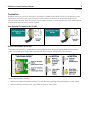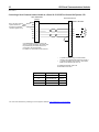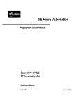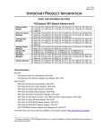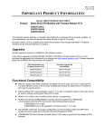
1
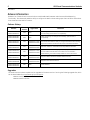
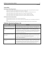
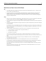
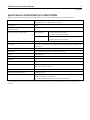
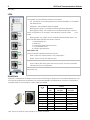
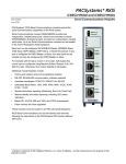
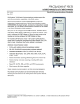
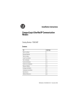
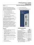
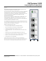
PACSystems* RX3i IC695CMM002 and IC695CMM004 GFK-2461J July 2014 PACSystems* RX3i Serial Communications modules expand the serial communications capabilities of the RX3i system. Serial Communications Modules Serial Communications module IC695CMM002 provides two independent, isolated serial ports. Serial Communications module IC695CMM004, illustrated at right, provides four independent, isolated serial ports. Up to six Serial Communications modules can be located in the main PACSystems RX3i backplane. Each port can be configured for MODBUS Master, MODBUS Slave, CCM Slave, DNP3 Master, DNP3 Slave, or Serial I/O protocol. If any port is configured for DNP3 Master or Slave, the other ports on the module can only be configured for DNP3 Master or Slave. For modules with firmware version 1.32 or later, half-duplex flow control can be configured using Machine Edition Release 5.90, SP1, SIM 6 or later. Otherwise, flow control defaults to full-duplex. Additional module features include: ▪ Port-to-port isolation and port-to-backplane isolation ▪ RS-232, RS-485/422 communication, software-selected ▪ Hardware handshake: RTS/CTS, RFR/CTS for RS-232 ▪ Selectable Baud Rates: 1200, 2400, 4800, 9600, 19.2K, 38.4K, 57.6K, 115.2K ▪ Module fault status reporting (Watchdog, Ram Fail, Flash Fail) ▪ Module identity and status reporting, including LED status indicators ▪ Meets CE, UL/CUL 508 and 1604, and ATEX requirements ▪ Flash memory for future upgrades These modules must be located in an RX3i Universal Backplane. RX3i Serial Communications can be hot-inserted and removed following the instructions in the PACSystems RX3i System Manual, GFK-2314E. * Indicates a trademark of GE Intelligent Platforms, Inc. and/or its affiliates. All other trademarks are the property of their respective owners. 2 RX3i Serial Communications Modules GFK-2461J Release Information Release 1.34 of the Rx3i serial communications module adds DNP3.0 Master and Slave Unsolicited Reporting functionality. The release also adds the ability to configure the DNP3.0 Slave Analog Input Event Variation and resolves three issues with the DNP3.0 firmware. Release History Release Firmware Version IC695CMM002-CF IC695CMM004-CF 1.34 N/A This change addresses a component obsolescence issue. No change in functionality, performance or compatibility. IC695CMM002-BF IC695CMM004-BF 1.34 N/A Label change only. No change in functionality, performance or compatibility. IC695CMM002-AF IC695CMM004-AF 1.34 44A753277-G06 44A753278-G06 Adds DNP3.0 Master and Slave Unsolicited Reporting functionality. The release also adds the ability to configure the DNP3.0 Slave Analog Input Event Variation and fixes three issues in the DNP3.0 firmware IC695CMM002-AE IC695CMM004-AE 1.32 44A753277-G05 44A753278-G05 See GFK-2461E for new features and problems resolved. IC695CMM002-AD IC695CMM004-AD 1.30 44A753277-G04 44A753278-G04 Supports Serial Protocol Language (SPL) scripting. Corrects DNP3 Slave Bit Write issue. Please refer to M050803 IC695CMM002_004 Product Safety Bulletin for more information. IC695CMM002-AC IC695CMM004-AC 1.20 44A753277-G03 44A753278-G03 Supports DNP3 Master and DNP3 Slave Protocol IC695CMM002-AB IC695CMM004-AB 1.10 44A753277-G02 44A753278-G02 Supports CCM Slave Protocol IC695CMM002-AA IC695CMM004-AA 1.00 N/A Initial Release Upgrade Kit Comments Upgrades The Serial Communications Modules can be upgraded to firmware version 1.34 using the following upgrade kits, which can be downloaded from http://www.ge-ip.com/support. CMM002: 44A753277-G06 CMM004: 44A753278-G06 3 RX3i Serial Communications Modules GFK-2461J Compatibility Programmer Version Requirements Proficy* Machine Edition Logic Developer 6.00 with SIM 12 or later version is required for DNP3 Unsolicited Response functionality and Analog Input Event Variation configuration. Proficy Machine Edition Logic Developer 5.9 SP1 with SIM 6 is required for half duplex flow control Proficy Machine Edition Logic Developer 5.8 with SIM 2 or newer is required to use SPL Proficy Machine Edition Logic Developer 5.6 with SIM 10 or newer is required to use DNP3 Proficy Machine Edition Logic Developer 5.6 with SIM 6 or newer is required to use the CMM CPU Firmware Version Requirements PACSystems RX3i CPU Version 5.50 or newer is required for SPL PACSystems RX3i CPU Version 5.00 or newer is required for DNP3 Master to sync its timestamp value with the CPU. PACSystems RX3i CPU Version 3.83 or newer is required to be able to use the CMM in the RX3i system. Problems Resolved by Release 1.34 Title Description DNP3 Master – The module does not read multiple group objects for Class 0 data When multiple group objects (i.e. %I and %AI memory) are performed in a single request the DNP3 module will ignore all but the first object. Operations of multiple group objects should be split into multiple successive exchanges (i.e. exchange 1 - %I, exchange 2 - %AI). SPL, Serial I/O, Modbus Master, DNP3 Slave - CMM002/004 generates blink code 1 Sending large amounts of data without reading can cause the module to generate a watchdog expired error , indicated by blink code 1. The amount of data that causes this error depends on the baud rate used. For example, a port configured for SPL and sending 4k bytes of data at 19.2k baud or 62k bytes of data at 115.2k baud will produce the error. With DNP3 protocol, the creation of change events while previous change events are being read can also produce the error. DNP3 - An incomplete or null response from a slave will result in erroneous values written A read operation data exchange (Read Continuous, Read Continuous Bit-Controlled, Read Single Bit-Controlled) that requests Ref Length 1 or greater from an outstation that does not return all, or returns none of the data points requested, will result in erroneous values being written to the reference addresses defined in that exchange. If a slave does not map all of the data points requested, it will return no data or only part of the data requested. DNP3 - Additional slave data exchanges of the same Object type are not ignored. The slave module does not ignore second data exchanges of the same object type. For example, a slave is configured with two Read/Write Analog Input Deadband exchanges, the first with length 2 and the second with length 5. When the master reads the Analog Input Deadband data, two data points from the second exchange are returned. The intended operation is that only the first configured exchange of a type is executed, so in the example only two data points from the first exchange should be returned. 4 RX3i Serial Communications Modules GFK-2461J New for Release 1.34 DNP3.0 Unsolicited Response Support The Serial Communications Modules now support DNP3.0 Unsolicited Responses for Master and Slave. Unsolicited Response functionality is configurable with Proficy Machine Edition Logic Developer 6.0 with SIM 11. The default configuration sets Unsolicited Response support to disabled. When this feature is enabled, the outstation can spontaneously transmit a response without first receiving a request for data. This feature provides the ability for the outstation to notify the Master as soon as possible after a change occurs. See "Handling of Unsolicited Responses" in chapter 8 of the PACSystems RX3i Serial Communications Modules User's Manual, GFK-2460D. DNP3.0 Analog Input Event Variation configuration The Analog Input Event Variation can be selected between 16 bit values without time and 16 bit values with time. This is configurable with Proficy Machine Edition Logic Developer 6.0 with SIM 12 and later. The default configuration sets the Analog Input Event Variation to 16 bit values without time. The new Analog Input Event Variation parameter allows you to select the format for sending analog input event data when Variation 0 (“Any”) is selected. If the default selection, Variation 2, is chosen, the Slave device sends the data as 16-bit integer with flag. If Variation 4 is selected, the Slave device sends the data as 16-bit integer with flag and event time stamp. See "Configuring a Port for DNP3 Slave Protocol" in chapter 3 of the PACSystems RX3i Serial Communications Modules User's Manual, GFK-2460D. 5 RX3i Serial Communications Modules GFK-2461J Restrictions and Open Issues in this Release SPL 1. The module rejects a SPL program file containing a literal string of length greater than 127. The SPL port will return a status in the status byte of 61. 2. The static file checker can miss paired NEXT and FOR statements. If a NEXT statement is missing from the program, execution will continue without looping back to the FOR statement. Users should check their FOR/NEXT statements before downloading. A missing NEXT statement can also be detected by debugging using the CLI debug interface. Other 3. Each port can be configured for DNP3 Master or DNP3 Slave protocol. If any port is configured for DNP3 Master or Slave, the other ports on the module can only be configured for DNP3 Master or Slave. 4. These modules do not support GE Intelligent Platforms special MODBUS commands for use with a Daniels Flow Computer. 5. PLC Reference Address and Reference Length parameters only allow bit based memory values that are aligned to a byte boundary. For example, for a port using MODBUS Slave with coils mapped to %Q memory, the %Q memory address must start on a byte boundary in %Q. (Target Address 1 can be mapped to %Q00001 or %Q00009, but it can not be mapped to %Q00007.) 6. CCM Slave Read Scratchpad operations may fail when a port is configured for CCM Slave protocol and: ▪ a new configuration is stored to the PLC using Machine Edition, or ▪ the system is power-cycled, or ▪ the module is hot-inserted If the first query received from the CCM Master is a Read Scratchpad request, the module will reject that request. All subsequent Read Scratchpad requests will be successful unless one of the above conditions occurs again. 7. The DNP3 slave port has problems using the link layer to validate frame receipt. The DNP3 organization encourages users not to do this. 8. Change Event Read responses are not sent immediately after a Confirm to an unsolicited response. If a read request is received after sending an unsolicited response, the slave is required to wait to respond to the read until either the unsolicited timeout expires, or the unsolicited message is confirmed. The module waits until the timeout expires, even if the unsolicited message has been confirmed, to send the read response. Normally, messages are responded to within milliseconds, but the read response does not occur for up to 2 seconds after the confirm message is sent. 6 RX3i Serial Communications Modules GFK-2461J Operating Notes SPL 1. In the error message, brackets [ ] are printed only around the key failing token. When looking at the error message the entire line should be interpreted. Example: --- Script file --i = 128 ) --- Error output--Error [3184]: line 1 i = [128] ) 2. An SPL wrong error is reported when a “(“ is in an IF statement. IF statements only support comparisons of variables and constants. Using () to enclose operations (like arithmetic operations or comparisons) will result in a syntax error. The module will report this error as an unknown identifier for the () symbols rather than a syntax error. 3. If the SPL program writes to memory that is invalid in the PLC the write will fail and the SPL program will halt. Other 1. DNP3.0 configurations with Unsolicited Response support enabled or Analog Input Event Variations set to other than 16 Bit Values Without Time, will result in a System Configuration Mismatch fault. If any of these configuration is downloaded to a module with firmware earlier than Release 1.34, the module configuration will fail. 2. The maximum resolution for the MODBUS drop delay is 420μs, so the minimum time for a drop delay is 420μs. 3. If retentive memory is used for Port Control Data, when a power cycle with battery or hot swap of the CMM module occurs, all exchanges whose control bit is in the ON state will be re-executed on the next PLC output scan or output DO I/O. To prevent this, all exchange control bits must be cleared by the application logic on the initial PLC logic scan or upon detection of CMM module removal. Installation in Hazardous Locations EQUIPMENT LABELED WITH REFERENCE TO CLASS I, GROUPS A, B, C & D, DIV. 2 HAZARDOUS LOCATIONS IS SUITABLE FOR USE IN CLASS I, DIVISION 2, GROUPS A, B, C, D OR NON-HAZARDOUS LOCATIONS ONLY WARNING - EXPLOSION HAZARD - SUBSTITUTION OF COMPONENTS MAY IMPAIR SUITABILITY FOR CLASS I, DIVISION 2; WARNING - EXPLOSION HAZARD - WHEN IN HAZARDOUS LOCATIONS, TURN OFF POWER BEFORE REPLACING OR WIRING MODULES; AND WARNING - EXPLOSION HAZARD - DO NOT CONNECT OR DISCONNECT EQUIPMENT UNLESS POWER HAS BEEN SWITCHED OFF OR THE AREA IS KNOWN TO BE NONHAZARDOUS. 7 RX3i Serial Communications Modules GFK-2461J Specifications: IC695CMM002 and IC695CMM004 Refer to the PACSystems RX3i System Manual, GFK-2314, for product standards and general specifications. Number of Serial Ports IC695CMM002: two independent serial ports IC695CMM004: four independent serial ports Connectors RJ-45 Number of Serial Communications Modules per CPU Six in the main CPU backplane Backplane power requirements IC695CMM002 0.7 Amps maximum @ 3.3Vdc 0.115 Amps maximum @ 5.0Vdc IC695CMM004 0.7 Amps maximum @ 3.3Vdc 0.150 Amps maximum @ 5.0Vdc LEDs Module OK, Port Fault, Port Status (2 or 4) Port Type RS-232 or RS-485/22. 4-wire (full duplex) or 2-wire (half-duplex) operation for RS-485/422 Flow Control for RS-232 Selectable: Hardware (RTS/CTS, RFR/CTS) or none Baud rates 1200, 2400, 4800, 9600, 19.2K, 38.4K, 57.6K, 115.2k Parity Even, odd, none Data bits 7, 8 Stop bits 1, 2 Operating Temperature 0C to + 60C Input Impedance Zin > 96 k for RS-485/422 3 k < Zin < 7 k for RS-232 Max Overvoltage ±25V Channel-Channel Crosstalk –55dB minimum Isolation Port to Backplane and to frame ground: 250Vac continuous; 1500Vac for 1 minute, 2550Vdc for one second. Port to port: 500Vdc continuous, 710Vdc for one minute. To meet emission and immunity requirements for the EMC directive (CE mark), shielded cable must be used with this module. 8 RX3i Serial Communications Modules GFK-2461J LEDs MODULE OK LED The MODULE OK LED indicates the status of the module. Off: The module is not receiving power from the RX3i backplane, or the module has failed self test. Solid green: The module has been configured. Blinking green, rapidly: The module is executing powerup diagnostics. Blinking green, slowly: The module has not received configuration from the CPU. If configuration is not successful, the module will continue to flash in this mode. Blinking amber: If a problem occurs, the Module OK LED flashes amber. The blink code (see below) indicates the cause of the error. 1 = watchdog expired 2 = RAM error 6 = Invalid CPU Master Interface version 7 = CPU heartbeat failure 8 = Failed to get semaphore PORT FAULT LED The Port Fault LED indicates the status of all ports. Green: There are no faults present on any enabled port. Amber: There is a fault on at least one port. Port STATUS LEDs A port’s STATUS LED blinks green when there is activity on the port and data rate matches the port configuration. The area below the module LEDs can be used to record identifying information about each port. Serial Ports Each port is a standard RJ-45 female connector with the following pin assignments. For MODBUS applications, note that these pin assignments are different from the standard MODBUS pin assignments. If the port is configured for MODBUS master or slave operation, custom cables are needed. RJ-45 Pin 8 Pinouts RS-232 DTE COM RS-485/422 Two-Wire GND 7 RS-485/422 Four-Wire GND Termination 2 6 CTS 5 COM 4 Rx- (Input) GND GND Termination 1 3 RxD 2 TxD Tx- / Rx- Tx- (Output) 1 RTS/RFR Tx+ / Rx+ Tx+ (Output) Note: There is no shield or frame ground pin on the port connector. Rx+ (Input) 9 RX3i Serial Communications Modules GFK-2461J Termination By default, each port is set for no termination. Termination is needed if the module is the first or last device on an RS485 network, even if there is only one other device on the network. Termination can be provided using either an external resistor as shown below or the port’s built-in 120 termination. If line termination other than 120is required, an appropriate external resistor must be supplied. User-Supplied Termination for RS-485 Built-in Termination for RS-485 Termination using the built-in 120 resistor can be provided by either setting the appropriate RS-485 termination jumper or by installing shorting jumpers on the RS-485 cable connector that attaches to the serial port. To set 120 termination internally: 1. Remove the module’s faceplate by pressing in on the side tabs and pulling the faceplate away from the module. 2. With the module oriented as shown, move either the upper or lower jumper. 10 RX3i Serial Communications Modules GFK-2461J Connecting a Serial Communications Module to a Series 90-30 CPU363 or External PACSystems CPU RX3i CMM002/004 Module GND Note: The same ground is required at each unit. Use either or both GND connectors (pins 8 and 5.) Built-in RS-485 Port 7 SIGNAL GROUND 8 NC 7 14 GND 5 15 Rx+ 3 13 Tx+ Rx- 6 12 Tx- Tx+ 1 11 Rx+ Tx- 2 10 Rx- NC 4 * 8 ** 9 6 If the CMM002/004 module is the first or last device on the RS-485 network, termination must be provided using an external resistor or the port’s built-in 120-Ohm termination. For details, see “Termination” in this document. 5 4 3 2 1 * ** To provide termination using an external resistor, connect a user-supplied resistor across pins 10 and 11. To provide termination using the built-in 120Ω resistor, install a jumper between pins 9 and 10. For additional port details, refer to the documentation for the CPU. Signal Name Description Direction Tx+ Transmitted Data + Output Tx- Transmitted Data - Output Rx+ Received Data + Input Rx- Received Data - Input For technical assistance, please go to the Support website, http://www.ge-ip.com/support.