1
GE Fanuc Automation
Programmable Control Products
Field Control™
Genius® Bus Interface Unit
User’s Manual
GFK-0825F
October 1999
GFL-002
Warnings, Cautions, and Notes
as Used in this Publication
Warning
Warning notices are used in this publication to emphasize that hazardous voltages,
currents, temperatures, or other conditions that could cause personal injury exist in this
equipment or may be associated with its use.
In situations where inattention could cause either personal injury or damage to
equipment, a Warning notice is used.
Caution
Caution notices are used where equipment might be damaged if care is not taken.
Note
Notes merely call attention to information that is especially significant to understanding and
operating the equipment.
This document is based on information available at the time of its publication. While efforts
have been made to be accurate, the information contained herein does not purport to cover all
details or variations in hardware or software, nor to provide for every possible contingency in
connection with installation, operation, or maintenance. Features may be described herein
which are not present in all hardware and software systems. GE Fanuc Automation assumes no
obligation of notice to holders of this document with respect to changes subsequently made.
GE Fanuc Automation makes no representation or warranty, expressed, implied, or statutory
with respect to, and assumes no responsibility for the accuracy, completeness, sufficiency, or
usefulness of the information contained herein. No warranties of merchantability or fitness for
purpose shall apply.
The following are trademarks of GE Fanuc Automation North America, Inc.
Alarm Master
CIMPLICITY
CIMPLICITY 90–ADS
CIMSTAR
Field Control
GEnet
Genius
Helpmate
Logicmaster
Modelmaster
Motion Mate
PowerTRAC
ProLoop
PROMACRO
Series Five
Series 90
Series One
Series Six
Series Three
VersaMax
VersaPro
VuMaster
Workmaster
©Copyright 1996-1999 GE Fanuc Automation North America, Inc.
All Rights Reserved.
Preface
Content of this Manual
This manual describes the Field Control® Genius™ Bus Interface Unit (IC670GBI002). It explains
operation of the Bus Interface Unit as a Genius bus device. It also contains complete configuration
instructions for the Bus Interface Unit and all Field Control I/O modules.
Chapter 1. Introduction: Chapter 1 introduces Field Control systems, the Genius Bus Interface
Unit, and other equipment that may be used with the Bus Interface Unit. It will help you locate
more information about the components and operation of Field Control products.
Chapter 2. Description: Chapter 2 describes the Genius Bus Interface Unit module, the Bus
Interface Unit Power Supply, and the Bus Interface Unit Terminal Block, and lists their
specifications.
Chapter 3. Installation: Chapter 3 describes Bus Interface Unit installation and gives system
installation guidelines.
Chapter 4. Operation: Chapter 4 explains how a Bus Interface Unit interacts with the modules in
its station, how it stores data, and how it exchanges data with a PLC or other type of system host.
Chapter 5. Station Configuration: Chapter 5 explains how to configure a Bus Interface Unit and
the modules in a station using a Hand-held Monitor.
Chapter 6. Diagnostics and Fault Clearing: Chapter 6 describes the diagnostics capabilities of
the Bus Interface Unit and explains how faults are cleared.
Chapter 7. Monitoring and Controlling Field Control Data: Chapter 7 explains how to monitor
or control Field Control I/O data using Genius Hand-held Monitor or a programmer.
Chapter 8. Datagrams: Chapter 8 lists datagrams that can be sent to a Bus Interface Unit, and
shows the datagram formats for Field Control modules.
Appendix A. Scaling Analog Channels: Appendix A explains how to select scaling values when
configuring an analog input or output. (Configuration instructions are in chapter 5).
Appendix B. Installing Additional Suppression: Appendix B describes some precautions that
can be taken in an installation to help assure proper operation.
Appendix C. The Genius Serial Bus: This appendix describes the selection and operating
characteristics of the bus cable that links Genius devices.
Appendix D. Configuration Examples: This appendix includes examples of different Field Control I/O
Station configurations.
GFK-0825F
iii
Preface
Related Publications
For more information, refer to these publications:
Field Control I/O Modules User's Manual (GFK-0826). This book describes Field Control I/O
Modules and I/O Terminal Blocks and explains how to install them.
The Series 90® Micro Field Processor User's Manual (GFK-1171). This book describes the
Micro Field Processor (IC670MFP100) and provides installation procedures, operation
information, and diagnostics information.
Genius I/O System User's Manual (GEK-90486-1). Reference manual for system designers,
programmers, and others involved in integrating Genius I/O products in a PLC or host computer
environment. This book provides a system overview, and describes the types of systems that can be
created using Genius products. Datagrams, Global Data, and data formats are defined.
Series 90® −30 Bus Controller User's Manual (GFK-1034). Reference manual for the Bus
Controller, which interfaces a Genius bus to a Series 90-30 PLC. This book describes the
installation and operation of the Bus Controller.
Series Six® Bus Controller User's Manual (GFK-0171). Reference manual for the Bus Controller,
which interfaces a Genius bus to a Series Six PLC. This book describes the installation and
operation of the Bus Controller. It also contains the programming information needed to interface
Genius I/O devices to a Series Six PLC.
Series Five® Bus Controller User's Manual (GFK-0248). Reference manual for the Bus
Controller, which interfaces a Genius bus to a Series Five PLC. This book describes the installation
and operation of the Bus Controller. It also contains the programming information needed to
interface Genius I/O devices to a Series Five PLC.
Genius I/O PCIM User's Manual (GFK-0074). Reference manual for the PCIM, which interfaces
a Genius bus to a suitable host computer. This book describes the installation and operation of the
PCIM. It also contains the programming information needed to interface Genius I/O devices to a
host computer.
Installation Requirements for Conformance to Standards (GFK-1179)
Jeanne Grimsby
Lead Technical Writer for I/O Products
iv
Field Control™ Genius® Bus Interface Unit User’s Manual– October 1999
GFK-0825F
Contents
Chapter 1
Introduction..................................................................................................... 1-1
Overview...................................................................................................................... 1-1
Field Control Modules .................................................................................................. 1-2
Environmental Specifications........................................................................................ 1-5
Configuration for Field Control..................................................................................... 1-6
Field Control in a Genius System.................................................................................. 1-7
Required Genius and Host System Equipment............................................................... 1-9
Using Field Control in a CPU Redundancy System ..................................................... 1-10
Using Field Control in a Genius Bus Redundancy System........................................... 1-11
Chapter 2
Description....................................................................................................... 2-1
Genius Bus Interface Unit............................................................................................. 2-1
Bus Interface Unit Power Supply .................................................................................. 2-3
Backplane Current ........................................................................................................ 2-4
Bus Interface Unit Power Dissipation............................................................................ 2-5
Load Requirements for Hardware Components ............................................................. 2-6
Bus Interface Unit Terminal Block................................................................................ 2-8
Functional Specifications .............................................................................................. 2-9
Chapter 3
Installation....................................................................................................... 3-1
Preinstallation Check .................................................................................................... 3-2
Static Protection............................................................................................................ 3-2
Hand-held Monitor Connector ...................................................................................... 3-2
System Wiring Guidelines ............................................................................................ 3-3
Installing Additional Suppression.................................................................................. 3-3
System Grounding ........................................................................................................ 3-4
Locations for Field Control........................................................................................... 3-5
Installing the DIN Rail.................................................................................................. 3-5
Installing the Bus Interface Unit Terminal Block on the DIN Rail ................................. 3-7
Installing the Cables Between Terminal Blocks............................................................. 3-8
Power Wiring to the Bus Interface Unit......................................................................... 3-9
Connecting the Communications Bus.......................................................................... 3-10
Bus Cables.................................................................................................................. 3-10
Making Bus Connections ............................................................................................ 3-11
Installing the Bus Interface Unit on the Terminal Block .............................................. 3-14
Removing the Bus Interface Unit from the Terminal Block ......................................... 3-14
Removing/Replacing the Bus Interface Unit Fuse ....................................................... 3-15
Upgrading the BIU Firmware...................................................................................... 3-16
GFK-0825F
v
Contents
Chapter 4
Operation......................................................................................................... 4-1
BIU Data Handling at the I/O Station............................................................................ 4-2
I/O Data for Conventional Modules .............................................................................. 4-3
I/O Data, Status Data, and Control Data for Intelligent Modules.................................... 4-3
Group Data for Intelligent Modules............................................................................... 4-4
The BIU Sweep ............................................................................................................ 4-5
BIU Backplane Scan Time............................................................................................ 4-7
Data Transfer Between the BIU and the Host ................................................................ 4-9
Data in the BIU's Network (Bus) Map........................................................................... 4-9
Communications on the Genius Bus.............................................................................. 4-9
Input Data Sent by the Bus Interface Unit ................................................................... 4-10
Outputs from the Host to the BIU................................................................................ 4-11
Genius Bus Scan Time................................................................................................ 4-12
Operation of the BIU with a Micro Field Processor ..................................................... 4-14
MFP and BIU Synchronization ................................................................................... 4-14
MFP I/O References ................................................................................................... 4-14
MFP Operating Modes................................................................................................ 4-14
Overview of Synchronous Operation........................................................................... 4-16
Backing Up Micro Field Processor Outputs ................................................................ 4-17
How the Network Backs Up MFP Outputs.................................................................. 4-18
Backing Up BIU Outputs with a Micro Field Processor............................................... 4-19
Example Ladder Logic................................................................................................ 4-20
Chapter 5
Station Configuration...................................................................................... 5-1
For Additional Information, Also See: .......................................................................... 5-1
Configuring the Serial Bus Address and Baud Rate....................................................... 5-2
Special Instructions for Series 90-70 PLC Systems ....................................................... 5-2
Set Up the Hand-held Monitor ...................................................................................... 5-3
Create a New Configuration.......................................................................................... 5-4
Assigning a Serial Bus Address to a New BIU .............................................................. 5-4
Configure the Bus Interface Unit................................................................................... 5-5
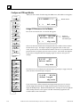
Field Control HHM Menu Overview............................................................................. 5-6
Change the Serial Bus Address of the Bus Interface Unit .............................................. 5-7
Select the Baud Rate..................................................................................................... 5-8
Select a Series Six or Series Five PLC Reference Address............................................. 5-9
Configure Fault Reporting .......................................................................................... 5-10
Configure Genius Bus Redundancy............................................................................. 5-11
Configure CPU Redundancy....................................................................................... 5-12
Configure Field Control Modules................................................................................ 5-15
Enable/Disable the I/O Scan ....................................................................................... 5-15
vi
Field Control™ Genius® Bus Interface Unit User’s Manual– October 1999
GFK-0825F
Contents
Disable Network I/O Updates ..................................................................................... 5-15
Configure the Network Map for the Bus Interface Unit ............................................... 5-16
Configuring Extra References in the BIU I/O Map...................................................... 5-17
Add Modules and Assign References .......................................................................... 5-20
Configure a Discrete Input Module ............................................................................. 5-22
Configure a Discrete Output Module........................................................................... 5-24
Configure a Discrete Input/Output Module.................................................................. 5-26
Configure a Conventional Analog Input Module ......................................................... 5-29
Configure a Conventional Analog Output Module....................................................... 5-35
Configure a 16-Point Grouped Analog Input Module .................................................. 5-40
Configure an 8-Point Grouped Analog Voltage Input Module ..................................... 5-48
Configure a 16-Point Grouped Analog Voltage Input Module ..................................... 5-56
Circuit Configuration.................................................................................................. 5-60
Configure an RTD Input Module ................................................................................ 5-64
Circuit Configuration.................................................................................................. 5-67
Configuring a Thermocouple Input Module................................................................. 5-72
Configure an 8-Point Analog Voltage Output Module ................................................. 5-81
Configure an 8-Point Analog Current Output Module ................................................. 5-90
Configure a Micro Field Processor.............................................................................. 5-99
Chapter 6
Diagnostics and Fault Clearing....................................................................... 6-1
Diagnostics and Fault Clearing for Intelligent Modules ................................................. 6-1
Diagnostics and Fault Clearing for the BIU and Conventional Modules......................... 6-2
Display and Clear Faults from a Genius Hand-held Monitor.......................................... 6-3
Display and Clear Faults from a PLC............................................................................ 6-5
Series 90 PLC: I/O Fault Table .................................................................................... 6-5
Series 90 PLC: PLC Fault Table ................................................................................... 6-5
Series Five or Series Six PLC ....................................................................................... 6-5
GFK-0825F
Contents
vii
Contents
Chapter 7
Monitoring and Controlling Field Control Data............................................ 7-1
Overview...................................................................................................................... 7-2
Forcing Circuits............................................................................................................ 7-2
Overriding I/O Circuits ................................................................................................. 7-2
Monitor/Control I/O Data: Genius Hand-held Monitor .................................................. 7-3
Forcing/Unforcing the Displayed Reference.................................................................. 7-5
Monitor/Control I/O Data: Series 90 PLC .................................................................... 7-6
Monitor/Control I/O Data: Series Six PLC or Series Five PLC..................................... 7-6
Monitor/Control I/O Data: Computer ............................................................................ 7-7
Chapter 8
Datagrams ....................................................................................................... 8-1
Datagram Types............................................................................................................ 8-2
Read Map ..................................................................................................................... 8-3
Read Map Reply........................................................................................................... 8-3
Write Map .................................................................................................................... 8-4
Report Fault Datagram Format...................................................................................... 8-5
Configuration Data ....................................................................................................... 8-7
Read Configuration Data .............................................................................................. 8-7
Set Bus Interface Unit Operating Mode....................................................................... 8-29
Set Micro Field Processor Operating Mode................................................................. 8-29
Intelligent Analog Module Recalibration Datagram..................................................... 8-30
Read I/O Forces.......................................................................................................... 8-32
Read I/O Forces Reply................................................................................................ 8-32
Read Slot Diagnostics ................................................................................................. 8-33
Read Slot Diagnostics Reply....................................................................................... 8-33
viii
Field Control™ Genius® Bus Interface Unit User’s Manual– October 1999
GFK-0825F
Contents
Appendix A
Scaling Analog Channels.................................................................................A-1
How Scaling Works..................................................................................................... A-1
Scaling Values for 1mV or 1µA Engineering Units: BIU Version 1.3........................... A-2
Scaling Values for 1mV or 1µA Engineering Units: BIU.............................................. A-3
Measuring Scaling Values............................................................................................ A-4
Example of Scaling an Analog Input ............................................................................ A-5
Appendix B
Installing Additional Suppression ..................................................................B-1
Suppression at the Power Lines.................................................................................... B-1
Suppression for Devices in an Enclosure...................................................................... B-2
Suppression at the Communications Line..................................................................... B-2
Appendix C
The Genius Serial Bus.....................................................................................C-1
Wiring Guidelines........................................................................................................ C-1
Electrical Interface....................................................................................................... C-2
Genius Transceiver Electrical Specification ................................................................. C-3
Selecting a Cable Type ................................................................................................ C-4
Serial Bus Waveforms ................................................................................................. C-5
Using Other Cable Types ............................................................................................. C-6
Serial Data Format....................................................................................................... C-8
Bus Access .................................................................................................................. C-9
Bus Length ................................................................................................................ C-10
Baud Rate Selection................................................................................................... C-10
Bus Ambient Electrical Information........................................................................... C-11
Lightning Transient Suppression................................................................................ C-11
Appendix D
Configuration Examples .................................................................................D-1
Example 1: Discrete Data, Network Processing............................................................ D-1
Example 2: Discrete and Analog Data, Network Processing ......................................... D-2
Example 3: Discrete and Analog Data, Network and Local Processing......................... D-3
Example 4: Discrete and Analog Data, Network and Local Processing and Group Data
Moves ...................................................................................................................... D-4
Example 5: Group Move............................................................................................. D-6
GFK-0825F
Contents
ix
Chapter
Introduction
1
This chapter introduces Field Control modules, the Genius Bus Interface Unit, and other
equipment that may be used with the Bus Interface Unit. It will help you locate more information
in other Field Control and Genius documents.
Overview
Bus
Interface
Unit
I/O
I/O
I/O
Field Control is a family of highly modular distributed I/O and control products. They are suitable
for use in a wide range of host architectures.
The heart of the Field Control system is the Bus Interface Unit. The Bus Interface Unit provides
intelligent processing, I/O scanning, and feature configuration for a group of up to eight I/O
modules. Together, the Bus Interface Unit and its modules make up a Field Control station (see the
illustration, left).
The Bus Interface Unit and I/O modules are enclosed in sturdy, compact aluminum housings. Bus
Interface Unit and I/O modules bolt securely to separate Terminal Blocks, which provide all field
wiring terminals. The I/O Terminal blocks are generic and allow different I/O module types to be
mounted on the same base. I/O Terminal Blocks are available with box-type terminals, barrier-type
terminals, or wire-to-board connectors. All Terminal Blocks must be mounted on a DIN rail. The
DIN rail, which serves as an integral part of the grounding system, can also be mounted on a panel.
Field Control Features
I/O
I/O
I/O
I/O
Features and benefits of Field Control include:
wiring savings
better up time
easy installation and maintenance
spare parts savings
low cost
feature flexibility
open architecture / adaptable to a variety of networks
distributed I/O
small, compact I/O modules with generic terminal wiring bases.
DIN rail mounted
I/O
GFK-0825F
1-1
1
Field Control Modules
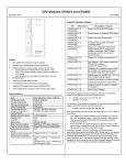
There are three basic types of Field Control modules:
Bus Interface Unit. The illustration below shows a Genius Bus Interface Unit.
I/O modules
Micro Field Processor
Terminal Blocks:
Bus Interface Unit Terminal Block.
I/O Terminal Blocks, each of which accommodates two I/O modules.
Auxiliary Terminal Blocks. These optional terminal strips can be connected to the side of
an I/O Terminal Block if extra common terminals are needed.
Bus Interface Unit
Terminal Block
Genius
Bus Interface Unit
Micro
Field Processor
Auxiliary
Terminal Blocks
1-2
I/O Terminal
Block
Field Control™ Genius® Bus Interface Unit User’s Manual – October 1999
I/O Modules
GFK-0825F
1
Genius Bus Interface Unit
The Genius Bus Interface Unit (IC670GBI002 or IC697GBI102) interfaces Field Control I/O
modules to a host PLC or computer via a Genius bus. It can exchange up to 128 bytes of input data
and 128 bytes of output data with the host, each Genius bus scan. It can also handle Genius
datagram communications.
The intelligent processing capabilities of the Genius Bus Interface Unit allow the configuration of
features such as fault reporting, selectable input and output defaults, analog scaling and analog
range selection for the modules in the station. In addition, the Genius Bus Interface Unit performs
diagnostic checks on itself and its I/O modules, and relays diagnostic information to the host (if
configured for fault reporting) and to a Hand-held Monitor.
The Genius Bus Interface Unit can be used on a bus controlled by redundant CPUs or Bus
Controllers. It can also be used on a dual bus.
The Bus Interface Unit mounts on a Bus Interface Unit Terminal Block. It can be removed and
replaced if necessary without removing the wiring or reconfiguring the I/O station.
Bus Interface Unit Terminal Block
The Bus Interface Unit Terminal Block, which included with the BIU, has connections for power
wiring and single or dual communications cables. It has built-in bus switching circuitry, allowing
the Bus Interface Unit to be used on a dual (redundant) Genius bus (no external Bus Switching
Module is needed). The Bus Interface Unit Terminal Block stores the configuration parameters
selected for the station.
I/O Modules
Field Control I/O Modules are available in many types to suit a wide range of application needs.
Modules can be installed and removed without disturbing field wiring. One or two I/O modules
may be mounted on an I/O Terminal Block.
Micro Field Processor
The Series 90 Micro Field Processor (MFP) is a Micro PLC that provides local logic within a Field
Control station. The Micro Field Processor is the same size as a Field Control I/O module and
occupies one of the eight available I/O slots in a Field Control station.
MFP features include:
Compatible with Logicmaster 90-30/20/Micro programming software, revision 6.01 or later.
Alarm processor
Password protection
Built-in communications port that supports Series 90 protocols (SNP and SNPX)
The Micro Field Processor requires a Genius Bus Interface Unit revision 2.0 or later.
GFK-0825F
Chapter 1 Introduction
1-3
1
I/O Terminal Blocks and Auxiliary I/O Terminal Blocks
An I/O Terminal Block provides mounting, electrical, and field wiring connections. Each half of
the I/O Terminal Block can be mechanically keyed to accept only an I/O module of a specific type.
Auxiliary I/O Terminal Blocks can be easily attached to an I/O Terminal Block. They can be used
to provide additional common terminals if needed.
For more information, please refer to:
Chapter 3: Installation, which explains wiring to the Bus Interface Unit, and explains how to
install the Bus Interface Unit module on the Field Terminal Block.
Chapter 2: Description, which describes the Bus Interface Unit and Bus Interface Unit Terminal
Block in detail.
Chapter 4, Operation, which explains how the Genius Bus Interface Unit services I/O.
Chapter 5: Hand-Held Monitor Configuration, which explains how to configure I/O modules.
The Series 90 Micro Field Processor User's Manual (GFK-1171), which describes the Micro
Field Processor (IC670MFP100) and provides installation procedures, operation information, and
diagnostics information.
The Field Control I/O Modules User's Manual (GFK-0826) which describes I/O modules and I/O
Terminal Blocks. This manual also explains module installation and field wiring.
1-4
Field Control™ Genius® Bus Interface Unit User’s Manual – October 1999
GFK-0825F
1
Environmental Specifications
Vibration
Noise
Modules perform well where vibration is a factor. Designs are shock and
vibration tested to meet the following specifications when installed on a
panel-mounted DIN rail using the clamp supplied, and with the panelmounting feet secured:
IEC68-2-6:
10 to 57 Hz 0.012 in displacement (peak to peak)
57 to 500 Hz at 2 g (unless otherwise specified)
IEC68-2-27:
Shock: 15G, 11 milliseconds, half sine wave
Modules are resistant to noise levels found in most industrial applications
when installed according to accepted practices, including proper separation
of wiring by voltage and power levels, on a conductive (unpainted) DIN rail.
The DIN rail is an integral part of the grounding system.
Modules are tested to the specifications listed in the Conformance to
Standards document (GFK-1079).
Temperature
Modules operate reliably in ambient air temperatures from 0 deg. C (32 deg.
F) up to 55 deg. C (131 deg. F).
Storage temperatures are -40 deg. C (-40 deg. F) to +85 deg. C (185 deg. F).
Humidity
5% to 95%, non-condensing.
For information about installing Field Control modules, please see:
Chapter 2 of this manual. It describes installation and wiring for the Bus Interface Unit module and
terminal block.
Chapter 2 of the Field Control I/O Modules User's Manual. It summarizes installation instructions
for modules and terminal blocks.
The individual module datasheets included in the Field Control I/O Modules User's Manual,
which provide specific module wiring information.
Chapter 2 of the Genius I/O System and Communications User's Manual, which includes detailed
instructions for selecting and installing a Genius bus.
GFK-0825F
Chapter 1 Introduction
1-5
1
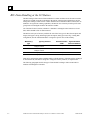
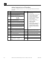
Configuration for Field Control
Configuration is an important part of the process of setting up a Field Control station. It establishes
the following features:
For the Bus Interface Unit:
Genius serial bus address
Baud rate for Genius bus communications
Fault reporting to the host
Use of the Bus Interface Unit as a bus switching device in a dual (redundant) bus system
Redundancy mode for CPU redundancy
Configuration protection
For I/O Modules:
I/O addressing
Whether faults will be reported to the host
Hold Last State for inputs or outputs
Output defaults
Range selection for analog modules
Scaling for analog modules
Alarm limits for analog modules
For a Micro Field Processor:
Reference addresses
Data Lengths
A Bus Interface Unit and I/O modules can be fully configured using a Hand-held Monitor.
Optionally, a previously-configured Bus Interface Unit can be reconfigured using datagrams.
For more information about configuration, please refer to:
Chapter 5 of this manual (HHM Configuration). A Genius Hand-held Monitor, version 4.6
(IC660HHM501J ) or later, can be used to configure a Bus Interface Unit. HHM configuration
instructions are given in chapter 5.
In addition, chapter 8 of this manual (Datagrams) explains how the configuration of a Bus
Interface Unit can be completed or changed by sending it Write Configuration datagrams.
The Series 90 Micro Field Processor User's Manual (GFK-1171), which describes the Micro
Field Processor (IC670MFP100), and provides installation procedures, operation information, and
diagnostics information.
If the system host is a Series 90™70 PLC, the Genius Bus Interface Unit must be included in the
system configuration as a device on the bus. Please see the programming software documentation
for instructions.
1-6
Field Control™ Genius® Bus Interface Unit User’s Manual – October 1999
GFK-0825F
1
Field Control in a Genius System
Using Field Control modules on a Genius bus combines the low cost, small size, and flexibility of
Field Control with the versatility, power, and communications features of the Genius system.
The Genius bus is an industrially-hardened Local Area Network (LAN). It passes I/O (control)
data and background information (datagrams) between the Bus Interface Unit and a Genius bus
controller. A Genius bus can support up to 32 devices. Each Bus Interface Unit station counts as
one device on the bus, regardless of the number or type of modules present in the station.
Other devices on the same bus can be Field Control stations, remote drops, I/O blocks, Bus
Controllers and Hand-held Monitors. Typical busses reserve one location for a Bus Controller and
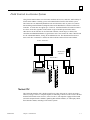
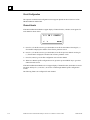
one for a Hand-held Monitor, leaving 30 for additional devices. The illustration below shows a
Series 90-70 PLC connected to a Genius bus with I/O blocks and two Field Control stations.
Series 90-70 PLC
Hand-held
Monitor
Genius Bus
The Host CPU
The Genius Bus Interface Unit is ideally suited for use with a Series 90-70 or Series 90-30 PLC.
However, any type of PLC or computer capable of controlling a Genius bus can be used as the host.
Possible hosts include Series Six PLCs, Series Five PLCs, and computers equipped with a PCIM
(Personal Computer Interface Module), QBIM (Q-Bus Interface Module), or a third-party GENIbased interface module, including several in DCS systems.
GFK-0825F
Chapter 1 Introduction
1-7
1
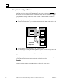
A More Complex Field Control and Genius System
A more complex communications and control system is illustrated below. In this system, the Field
Control stations and Genius blocks on the lower left are controlled by a Series 90-70 PLC. The
Field Control stations and Genius blocks on the lower right are controlled by a host computer
equipped with a PCIM (Personal Computer Interface Module).
The PLC communicates with a computer running programming software via an SNP (Serial
Network Protocol) link. And the PLC, host computer, and programmer computer exchange system
data via an Ethernet communications link.
Series 90-70 PLC
PCIM
SNP
Ethernet
Genius Bus
Genius Bus
For more information about Genius systems and communications, please refer to:
The Genius I/O System and Communications User's Manual, which describes Genius system
operation, and communications formats.
The Bus Controller User's Manual for the system host, which includes specific system interface
instructions.
1-8
Field Control™ Genius® Bus Interface Unit User’s Manual – October 1999
GFK-0825F
1
Required Genius and Host System Equipment
The following system equipment is required:
Genius Hand-held Monitor version 4.6 (IC660HHM501J) or later.
For a Series 90-70 PLC
Series 90-70 CPU firmware, release 3.0 or later.
A Series 90-70 Genius Bus Controller, release 3.0 or later. The Bus Controller must be 4.0
or later for full diagnostics display from Logicmaster 90-70, or for redundancy
applications.
If Logicmaster 90-70 programming and configuration software is used, it must be
release 3.0 or later:
A.
IC641SWP701F (3.5", 2DD, 5.25" 2S/HD)
B.
IC641SWP704C (5.25" 2S/2D)
For a Series 90 30 PLC
Series 90 30 CPU firmware: any version.
Logicmaster 90-30 programming and configuration software: any version.
Series 90-30 Genius Bus Controller: any version.
For a Series Six™ PLC
CPU: rev. 105 or later.
Logicmaster 6 Programming Software: release 4.02 or later.
Bus Controllers: IC660CBB902 or 903, version 1.7 or later.
For a Series Five™ PLC
CPU: rev. 3.2 (catalog number with E suffix) or later.
Logicmaster 5 Programming Software: release 2.01 or later.
Bus Controller: any version
For a Host Computer
GFK-0825F
PCIM: any version
QBIM: any version
Chapter 1 Introduction
1-9
1
Using Field Control in a CPU Redundancy System
Most systems use only one Bus Controller and CPU to control the I/O on the Genius bus. CPU
redundancy, which can be used for backup CPU/Bus Controller protection in critical applications,
is described in detail in the Genius documentation. The section that follows here summarizes how
Field Control products can fit into a Genius CPU Redundancy system.
CPU/Bus Controller Redundancy: Overview
In CPU redundancy, two Bus Controllers on the same bus can send control outputs at the same
time. Both Bus Controllers automatically receive inputs and fault reports from all devices on the
bus that have been configured as being in “CPU Redundancy” mode. The Bus Controllers must
use serial bus addresses (device numbers) 30 and 31.
Field Control stations can be used on a bus controlled by redundant CPUs/Bus Controllers.
Bus
Controller
(Device 30)
Bus
Controller
(Device 31)
46471
How the two sets of outputs from the dual CPUs are handled by a Bus Interface Unit depends on
whether the Bus Interface Unit is set up for Hot Standby or Duplex redundancy. If the station
contains any analog modules, the only form of CPU redundancy permitted is Hot Standby.
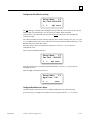
Hot Standby CPU Redundancy
A Bus Interface Unit configured for Hot Standby mode is normally controlled by the Bus
Controller assigned to serial bus address 31. If no outputs are available from 31 for three bus
scans, the Bus Interface Unit accepts outputs from the Bus Controller assigned to serial bus address
30. If outputs are not available from either Bus Controller, outputs go to their configured defaults
or hold their last state. In Hot Standby redundancy, Bus Controller-31 always has priority; when it
is on-line, it has control of the outputs.
Duplex CPU Redundancy
A Bus Interface Unit configured for Duplex mode compares outputs it receives from the two Bus
Controllers, to determine if they match. If corresponding outputs are the same, the Bus Interface
Unit sets the output to that state. If corresponding outputs are not the same, the Bus Interface Unit
sets the output to its configured ON or OFF Duplex Default State. If either Bus Controller stops
sending outputs to a Bus Interface Unit, its outputs are directly controlled by the remaining Bus
Controller. Only discrete I/O modules can operate in Duplex redundancy mode; do not use Duplex
mode if the station contains any analog I/O modules.
1-10
Field Control™ Genius® Bus Interface Unit User’s Manual – October 1999
GFK-0825F
1
Using Field Control in a Genius Bus Redundancy System
In Genius bus redundancy, there are two bus cables each connected to a Bus Controller. I/O
devices may be connected to either one bus of the pair, or to both. However, a device that is
connected to both busses actually communicates on only one bus at a time. Before the alternate
bus can be used for communications, a bus switchover must occur and the device must “log in”
with the Bus Controller(s) on the alternate bus.
The Bus Interface Unit Terminal Block contains a built-in bus switching relay that is used to switch
busses in a dual bus system. Other types of devices with this capability are dedicated Bus
Switching Modules and Series 90-70 Remote I/O Scanner modules. These are the only types of
devices that can be directly connected to both redundant bus cables.
A Bus Interface Unit cannot be used as the BSM Controller for a bus stub. Other devices cannot be
located on a stub downstream of a BIU.
Also, the Bus Interface Unit should not be connected to an external Bus Switching Module.
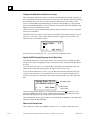
Redundant Bus Configurations
Many different redundant bus configurations are possible. Three basic ways of using a Bus
Interface Unit with a redundant bus are described below.
A Bus Interface Unit can be installed directly on both cables of the dual bus pair. The
Bus Interface Unit is configured to operate as a bus switching device in addition to performing
its normal functions. Here, two Field Control stations are installed on a dual bus. Each Bus
Interface Unit would be set up as a bus switching device.
Bus A
46472
Bus B
A Bus Interface Unit can be located on just one bus of a redundant bus pair, if bus
redundancy is not needed for the modules in that station. In this example, the Bus Interface
Unit on the left is connected to both Bus A and Bus B and is configured as a bus switching
device. The Bus Interface Unit on the right, which serves non-critical I/O modules, is
connected to Bus A only, and is not configured as a bus switching device.
Bus A
46473
Bus B
GFK-0825F
Chapter 1 Introduction
1-11
1
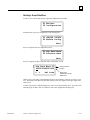
A Bus Interface Unit can be located on a bus stub. A Bus Interface Unit can also be located
on a bus stub, which is a short length of unterminated cable downstream of either a Genius I/O
block/Bus Switching Module combination, or a Remote I/O Scanner connected to a dual bus.
Because the bus stub cable itself is not redundant, this type of installation does not provide as
much protection as connecting directly to a dual bus. The bus switching device to which the
bus stub is connected can be another Genius block with a Bus Switching Module attached, as
shown below, or a Series 90-70 Remote I/O Scanner.
In this example, there are two Field Control stations installed on a bus stub. Each is
configured as “BSM Present” but not configured as a “BSM Controller”.
Bus A
46474
Bus B
Bus
Switching
Module
Genius Block
Acting as a
BSM Controller
Up to 7 Additional Devices on the Bus Stub
Up to seven devices (not counting the BSM/block or Remote I/O Scanner to which the dual bus is
connected) can be installed on a bus stub. Each device on a bus stub counts toward the total of 32
devices on the Genius bus.
Restrictions on the number and length of bus stubs that may be used on a dual bus are explained in
the Genius I/O System and Communications User's Manual.
1-12
Field Control™ Genius® Bus Interface Unit User’s Manual – October 1999
GFK-0825F
Chapter
Description
2
This chapter describes:
Genius Bus Interface Unit
Bus Interface Unit Power Supply
Bus Interface Unit Terminal Block
Specifications
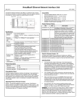
Genius Bus Interface Unit
The Genius Bus Interface Unit is a small, rugged, intelligent module with a sturdy aluminum
housing. The module has four status LEDs, described below, and a connector for attaching a
Genius Hand-held Monitor.
3.25" (8.2mm)
HHM
Connector
5.0" (12.7mm)
LEDs
The Bus Interface Unit contains the logic power supply needed to operate the I/O modules
connected to it. It mounts on a separate terminal block, to which it and all bus wiring are attached.
The configuration is stored in non-volatile memory located in the terminal block. Both the power
supply and terminal block are described in this chapter.
The Bus Interface Unit has a replaceable 1A, 5x20mm 250VAC slow-blow fuse on the input power
lines. The fuse can be changed without disturbing the wiring of any other modules (instructions are
in chapter 3).
GFK-0825F
2-1
2
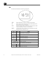
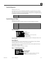
LEDs
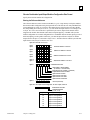
The LEDs on the Bus Interface Unit show its operating status.
lights to indicate that +5V power is available for logic operation.
OK
lights to indicate that the module has passed its powerup diagnostic tests.
See the table below for more information.
RUN
lights only if output modules are in the BIU configuration and are written
to by the controlling bus controller. See the table below.
BUS B
if the Bus Interface Unit is installed on a dual (redundant) bus, this LED
lights if Bus B is the currently-active bus.
OK
RUN
ON
ON
Module functioning, CPU communicating
ON
OFF
Module functioning, no CPU communications for 3 bus scans
ON
Blinking
Module functioning, circuit forced
Blinking
ON
Circuit fault, CPU communicating
Blinking
OFF
Circuit fault, no CPU communications for 3 bus scans
Alternate Blinking
Synchronous Blinking
2-2
BUS B PWR
ACTIVE
RUN OK
PWR
OFF
Blinking
OFF
OFF
Meaning
Circuit fault, Circuit forced
No CPU communications - block number conflict
Electronics/Terminal Assembly mismatch
No block power, or Block faulty
Field Control™ Genius® Bus Interface Unit User’s Manual – October 1999
GFK-0825F
2
Bus Interface Unit Power Supply
The power supply in the Bus Interface Unit provides power for the Bus Interface Unit itself and
logic power for all I/O modules that may potentially be installed at that station. External power
must be supplied for field wiring of input and output devices.
The power supply is not damaged by either of the following:
Reversing input voltage on terminals 1 and 2.
Temporary overcurrent conditions on the 6.5 VDC output.
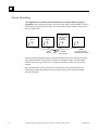
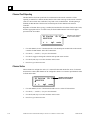
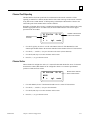
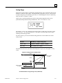
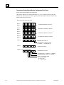
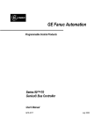
Timing
The Bus Interface Unit provides power to all I/O modules that are installed at the station. I/O
module operation is governed by a System Reset signal to ensure controlled operation during the
power up and shut down processes. As shown in the timing diagram below, momentary power
losses of less than 10 mS (for 24VDC BIU) or 20mS (for 115VAC/125VDC BIU) do not affect I/O
module operation. Longer power losses generate a Reset for all system I/O modules.
Input Power
On
24VDC
Nominal
or 115 VAC
Nominal
Input Power
Off
Momentary
Power
Loss
Voltage
Overshoot
5% (max)
6.5V Output
95% (min)
200mS
(min)
Voltage
Overshoot
5% (max)
Hold
Up
Time
Minimum:
10mS for 24VDC BIU
20mS for 115VAC/125VDC BIU
Hold
Up
Time
200mS
(min)
3mS
(min)
10mS
(min)
3mS
(min)
RST*
GFK-0825F
Chapter 2 Description
2-3
2
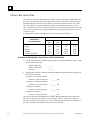
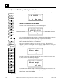
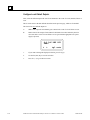
Backplane Current
With a DC input voltage, the amount of current available to the backplane may be limited by lower
input voltage as indicated below.
For 24VDC Supply
Backplane
Current
Available
(Amps)
For 125VDC Supply
Backplane
Current
Available
(Amps)
1.4
1.2
1.0
18
2.0
1.8
105 110
19 21
Voltage In
Voltage In
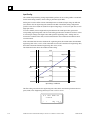
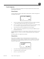
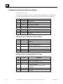
Calculating Input Power Requirements for a Bus Interface Unit
The charts below show typical input power requirements for a Bus Interface Unit.
For 24VDC Bus Interface Unit
For 115VAC/125VDC Bus Interface Unit
15.9
24.0
14.1
Typical
Input 18.75
Power
(Watts)
13.5
for DC
Inputs
Typical 12.3
Input
Power 10.0
(Watts)
7.7
48.0
37.75
27.5
17.25
8.25
5.5
3.4
7.0
3.0
0
0.25 0.50 0.75 1.00 1.20 1.40
0
Total Backplane Current (Amps)
Typical
Input
Power
(Volt/Amps)
for AC
Inputs
0.50
1.00
1.50
2.0
Total Backplane Current (Volts)
Note
For a 24VDC Bus Interface Unit, start-up surge at full load is 15-50 Amps for 3
milliseconds (maximum). For a 115VAC/125VDC Bus Interface Unit, startup
surge at full load is 20 Amps peak for 3mS.
To determine specific system requirements:
2-4
Determine total output load from typical specifications listed for individual modules.
Use the appropriate graph of input power above to determine average input power.
Divide the input power by the operating source voltage to determine the input current
requirements.
Use the lowest input voltage to determine the maximum input current.
Allow for startup surge current requirements. Startup surge current levels are a function of
source impedance and, therefore, are installation-dependent. Startup surge currents can vary
for approximately 3mS. For the 24VDC Bus Interface Unit, variance is between 25A and 50A.
For the 115VAC/125VDC Bus Interface Unit, startup surge current is 20A maximum peak.
Allow margins (10% to 20%) for variations.
Field Control™ Genius® Bus Interface Unit User’s Manual – October 1999
GFK-0825F
2
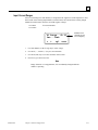
Bus Interface Unit Power Dissipation
The Bus Interface Unit power dissipation can be determined once the backplane current supplied to
the I/O modules is known.
The following equation can be used to calculate BIU power dissipation:
BIU Power Dissipation = Input Power - (total backplane current x 6.5 volts)
For example:
A. Total backplane current = 0.5 Amps
B. Typical Input power = 7.7 Watts
Therefore:
BIU Power Dissipation = 7.7 W - ( 0.5 x 6.5 ) = 4.45 Watts
GFK-0825F
Chapter 2 Description
2-5
2
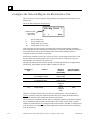
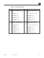
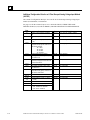
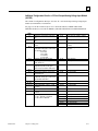
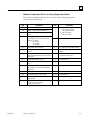
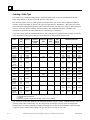
Load Requirements for Hardware Components
The table below shows the DC load required by each module and hardware component. All ratings
are in milliamps. Input and Output module current ratings are with all inputs or outputs on. These
are maximum requirements, not typical.
Catalog Number
IC670MDD441
IC670MDL233
IC670MDL240
IC670MDL241
IC670MDL640
IC670MDL641
IC670MDL642
IC670MDL643
IC670MDL644
IC670MDL730
IC670MDL740
IC670MDL742
IC670MDL330
IC670MDL331
IC670MDL930
Description
IC670ALG230
IC670ALG240
IC670ALG281
IC670ALG282
HE670ACC100
HE670ADC810
IC670ALG620
IC670ALG630
IC670ALG320
IC670ALG330
IC670MFP100
IC693PRG300
Mixed I/O Module, 24 VDC 10 Inputs, 6 Outputs
Input Module, 120 VAC 8 Isolated Points
Input Module, 120 VAC 16 Grouped Points
Input Module, 16 Points, 2 groups 240 VAC
Input Module, 24 VDC 16 Grouped Pos/Neg Points
Input Module, 48 VDC 16 Grouped Pos/Neg Points
Input Module, 125 VDC 16 Grouped Pos/Neg Points
Input Module, 5/12 VDC 16 Point
Input Module, 12/24 VDC 16 Grouped Pos/Neg Fast Inputs
Output Module, 8 Pt 24 VDC Electronic Short Circuit Protection
Output Module, 12/24 VDC 0.5 Amp, 16 Grouped Pos.
Output Module, 5/12/24 VDC Negative Outputs
Output Module, 16 Point 12-120 VAC 16 Pt 1.0 Amp
Output Module, 120 VAC 2 Amp, 8 Isolated Points
Relay Output Module, 2 Amp, 6 Form A Points and 2 Isolated
Form C Points
Analog Current Input Module, 8 Grouped Points
Analog Input Module, 16 point Grouped
Analog Voltage Input Module, 8 Grouped Points
Analog Voltage Input Module, 16Grouped Points
Input Simulator Module, Horner
Analog Input Module, Horner, +/-10VDC, 0-10 VDC
RTD Input Module
Thermocouple Input Module
Analog Current/Voltage Output Module, 4 Grp Points
Analog Current source Output Module, 8 Points
Micro Field Processor
Hand-held Programmer
IC660HHM501
Genius Hand-held Monitor
Current (mAmps)
110
40
77
77
83
83
77
80
80
125
111
111
285
154
313
51
251
150
150
100
131
190
195
51
85
111
170
0
Hand-held Monitor and Hand-held Programmer
The Genius Hand-held Monitor (IC660HHM501), used for configuring and monitoring the BIU,
has its own battery and does not add to the load on the BIU.
However, if a Hand-held Programmer (IC693PRG300) will be attached to a Micro Field Processor
or other module in the I/O Station, it must be considered as a load component as listed above.
2-6
Field Control™ Genius® Bus Interface Unit User’s Manual – October 1999
GFK-0825F
2
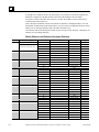
Hot Insertion/Removal of Modules
Bus Interface Units IC670GBI002(F) and IC670GBI102A or later support Hot Insertion/Removal
of modules in the I/O Station.
Hot Insertion/Removal means that modules can be removed and replaced while I/O Station power
is applied without affecting the BIU or other modules in the I/O Station. Separate I/O module
power must be switched off to the module being inserted or removed.
Hot Insertion/Removal requires the use of specific modules and I/O terminal blocks:
•
I/O modules having catalog number suffix J or above. These modules have a projecting
alignment tab that fits into a corresponding alignment tab on I/O Terminal Blocks listed below.
Note that modules with this tab can also be installed on older I/O Terminal Blocks that do not
have mating alignment tabs. However, Hot Insertion/Removal are not supported in such an
installation.
•
I/O Terminal Blocks IC670CHS101, 102, or 103. These I/O Terminal Blocks have projecting
alignment tabs designed to facilitate Hot Insertion/Removal of modules. Modules that are
earlier than revision J cannot be mounted on these terminal blocks.
I/O Terminal Blocks IC670CHS001, 002, and 003, which lack alignment tabs, do not support
Hot Insertion/Removal of modules. With these terminal blocks, I/O Station power should be
off when installing or removing modules.
Mixing IC670CHS10x terminal blocks with IC670CHS00x terminal blocks in the same I/O
station is not recommended.
Faults Reported During Hot Insertion/Removal
When using the recommended equipment listed above, Hot Insertion/Removal will cause the
expected fault reports related to the loss of or addition of the module and its I/O circuits. These
faults should be cleared in the normal manner. However, Hot Insertion/Removal of a rev. J or later
module will NOT cause Configuration Mismatch errors that in some types of systems can shut
down the controller.
I/O Module Data During Hot Insertion/Removal
As mentioned, separate I/O module power must be turned off for Hot Insertion/Removal. When the
module is installed and power is reapplied, module data will quickly return to normal. For
intelligent I/O modules, there may be a delay of a few seconds while the module goes through its
powerup sequence.
Hot Insertion/Removal for a Micro Field Processor
A Micro Field Processor that is revision J or later may be removed/inserted as described above.
Note, however, that although the Micro Field Processor will start functioning upon reinstallation,
the MFP's application program must be reloaded. I/O data controlled by the Micro Field Processor
will be incorrect until that has been done. (The BIU configuration of the Micro Field Processor is
not affected by Hot Insertion/Removal).
Hot Insertion/Removal Not Permitted in Hazardous Locations
In hazardous locations, I/O Station power must be turned off before inserting/removing module.
Failure to observe this precaution may result in personal injury, system malfunction and/or damage
to the equipment.
GFK-0825F
Chapter 2 Description
2-7
2
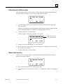
Bus Interface Unit Terminal Block
The Bus Interface Unit provides terminals for power and ground connections. Maximum wire size
is AWG #14. (avg 2.0690mm2 cross-section).
The Bus Interface Unit Terminal Block also has eight input terminals for connection to a single or
dual Genius bus. These terminals accommodate up to two AWG #14 wires. The Bus Interface Unit
Terminal Block contains bus-switching circuitry permitting it to be used as a BSM Controller in a
dual bus redundancy system.
A connecting cable is provided with each I/O Terminal Block. It is used to connect the Bus
Interface Unit Terminal Block to the first I/O Terminal Block. The same type of cable
interconnects subsequent I/O Terminal Blocks. The cable has molded connectors that are keyed to
assure proper orientation.
The Bus Interface Unit Terminal Block is designed to be extremely reliable; it should not be
necessary to replace or rewire it after installation.
The Bus Interface Unit Terminal Block stores the configuration parameters for the station. The Bus
Interface Unit can be removed without removing the wiring or reconfiguring the station.
46457
Terminals for
power and
communications
wiring
I/O Terminal Block
Connectors
Connecting
Cable
to next terminal block
2-8
Field Control™ Genius® Bus Interface Unit User’s Manual – October 1999
GFK-0825F
2
Functional Specifications
Bus Interface Unit:
Reliability
More than 183,000 hours operation MTBF, calculated
24VDC Power Supply Input
Nominal Rated Voltage
24 VDC
Voltage Range
18 VDC to 30 VDC
Power
16.8 Watts maximum at full load (nominal voltage)
Inrush Current
15-50 Amps peak, 3 mS maximum. Inrush current is installation
dependent. See page 2-4.
Power Supply Output
to I/O modules:
6.5 VDC ±5%
1.4 Amp maximum. See page 2-4.
Holdup Time
10mS maximum from nominal input voltage.
115VAC/125VDC Power Supply Input
Nominal Rated Voltage
115 VAC, 125 VDC
Voltage Range
90 to 135 VAC, 105 to 150 VDC
Frequency (AC)
47 to 63 Hz
Power
115 VAC: 48VA maximum at full load (nominal voltage)
125 VAC: 24W maximum at full load (nominal voltage)
Inrush Current
20 Amps peak, 3 mS maximum.
Power Supply Output
to I/O modules:
6.5 VDC ±5%
2 Amp maximum. See page 2-4.
Holdup Time
20mS maximum from nominal input voltage.
Bus Interface Unit Terminal Block:
Power Requirements
16mA maximum
Reliability
More than 600,000 hours operation MTBF, calculated
For power requirements of specific I/O modules, please see the Field Control I/O Modules User's
Manual, (GFK-0826).
GFK-0825F
Chapter 2 Description
2-9
Chapter
Installation
3
This chapter describes:
System Wiring Guidelines
System Grounding
Locations for Field Control Modules
Installing the Bus Interface Unit Terminal Block on a Panel
Installing the Bus Interface Unit Terminal Block on a DIN Rail
Installing the Cables Between Terminal Blocks
Power Wiring to the Bus Interface Unit
Connecting the Communications Bus
Installing/Removing the Bus Interface Unit
Removing/Replacing the Bus Interface Unit Fuse
Upgrading the BIU firmware.
For more information, please refer to:
The Field Control I/O Modules User's Manual for information about installing I/O modules.
Appendix C, “The Genius Serial Bus” for a detailed description of the characteristics of the Genius
bus.
GFK-0825F
3-1
3
Preinstallation Check
Carefully inspect all shipping containers for damage during shipping. If any part of the system is
damaged, notify the carrier immediately. The damaged shipping container should be saved as
evidence for inspection by the carrier.
As the consignee, it is your responsibility to register a claim with the carrier for damage incurred
during shipment. However, GE Fanuc will fully cooperate with you, should such action be
necessary.
After unpacking the Field Control modules and other equipment, record all serial numbers. Serial
numbers are required if you should need to contact Product Service during the warranty period of
the equipment.
All shipping containers and all packing material should be saved should it be necessary to transport
or ship any part of the system.
Static Protection
The Bus Interface Unit has CMOS components that are susceptible to static damage. Use proper
static handling techniques when handling this module.
Hand-held Monitor Connector
The connector on the Genius Bus Interface Unit is intended for use with a Genius Hand-held
Monitor only. It must be connected to a nonincendive circuit only.
HHM (must be connected to
a nonincendive circuit only)
3-2
Field Control™ Genius® Bus Interface Unit User’s Manual – October 1999
GFK-0825F
3
System Wiring Guidelines
Four types of wiring may be encountered in a typical factory installation:
1.
Power wiring - the plant power distribution, and high power loads such as high
horsepower motors. These circuits may be rated from tens to thousands of KVA at 220
VAC or higher.
2.
Control wiring - usually either low voltage DC or 120 VAC of limited energy rating.
Examples are wiring to start/stop switches, contactor coils, and machine limit switches.
This is generally the interface level of the Genius discrete I/O.
3.
Analog wiring - transducer outputs and analog control voltages. This is the interface level
to Genius I/O analog blocks.
4.
Communications and signal wiring - the communications network that ties everything
together, including computer LANs, MAP, and Genius I/O and communications bus.
These four types of wiring should be separated as much as possible to reduce the hazards from
insulation failure, miswiring, and interaction (noise) between signals. A typical PLC system with
Genius I/O may require some mixing of the latter three types of wiring, particularly in cramped
areas inside motor control centers and on control panels. In general, it is acceptable to mix the
communications bus cable with the I/O wiring from the blocks, as well as associated control level
wiring. All noise pickup is cumulative, depending on both the spacing between wires, and the
distance span they run together. I/O wires and communications bus cable can be placed randomly
in a wiring trough for lengths of up to 50 feet. If wiring is cord-tied (harnessed), do not include the
bus cable in the harness, since binding wires tightly together increases the coupling and mechanical
stress that can damage the relatively soft insulation of some serial cable types.
Wiring which is external to equipment, and in cable trays, should be separated following NEC
practices.
Installing Additional Suppression
It is possible some installations might exceed the surge immunity capabilities specified in chapter
1. This is most likely in outdoor installations or where the power source is from another building or
ground system. It is prudent to provide local transient protection.
Appendix B describes installation of additional suppression at the power and communications
lines.
GFK-0825F
Chapter 3 Installation
3-3
3
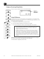
System Grounding
All components of a control system and the devices it controls must be properly
grounded. Ground conductors should be connected in a star fashion, with all branches routed to a
central earth ground point as shown below. This ensures that no ground conductor carries current
from any other branch.
Programming
Device
Each Terminal
Block
Earth
Ground
Motor Drives and
Other Electrical
Control
Equipment
Central
Ground Point
Machinery
NOTE
Signal and power
connections not shown
Each Field Control Terminal Block has a chassis ground terminal for safety and noise protection.
This terminal should be connected to the conductive mounting panel with a 4-inch maximum
length of AWG #14 (avg 2.1mm2) wire. Use hardware such as star washers to ensure ground
integrity.
The control panel and enclosure should also be bonded to the plant system ground per code.
Inadequate grounding may compromise system integrity in the presence of power switching
transients and surges.
3-4
Field Control™ Genius® Bus Interface Unit User’s Manual – October 1999
GFK-0825F
3
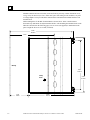
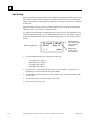
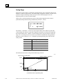
Locations for Field Control
Field Control terminal blocks must be installed on a 35mm x 7.5mm DIN rail. Modules can be
located on equipment, in junction boxes, inside panels, behind operator stations, in NEMA
enclosures as little as 4" deep, and in other locations where space is limited. The area should be
clean and free of airborne contaminants, with adequate cooling airflow.
Modules can be mounted in any orientation without derating the temperature specification. They
can be installed in a linear stack as shown on the left in the following illustration, using the short
connection cables provided with each I/O Terminal Block. An optional 21-inch (0.53 meter) cable
(IC670CBL002) is also available. Only one 21" cable can be used per Field Control station.
All of the I/O Terminal Blocks in a group must be connected either at the top or the bottom of the
Bus Interface Unit (BIU in the illustration). A Bus Interface Unit may not be connected between
I/O Terminal Blocks.
46405
BIU
BIU
BIU
BIU
Installing the DIN Rail
All Field Control Terminal Blocks must be mounted on a 7.5mm x 35mm DIN rail. The rail must
have a conductive (unpainted) finish for proper grounding.
For best vibration resistance, the DIN rail should be installed on a panel using screws spaced
approximately 6 inches (5.24cm) apart. When using multiple rail sections, be sure they are properly
aligned.
GFK-0825F
Chapter 3 Installation
3-5
3
Mount the DIN rail at least 4.25 inches (10.80 cm) from any wireway or other obstruction on the
wiring side of the Bus Interface Unit. Allow more space if the wiring for I/O modules is very stiff.
A wiring template is also provided in the instruction sheet included with each Bus Interface Unit
terminal block.
Drill mounting holes for the BIU Terminal Block as shown below. Allow a small tolerance
between the top and bottom of adjacent terminal blocks. After mounting the terminal blocks on the
DIN rail as described on the following pages, use #6 screws (not supplied) to attach them to the
panel. Length for all screws is 3/8 inch (9.525mm).
5.90in
14.99cm
4.25in
Wireway
4.50in
11.43cm
Clamp
Screw
1.75in
4.45cm
3-6
5.00in
12.70cm
4.31in
10.95cm
Field Control™ Genius® Bus Interface Unit User’s Manual – October 1999
GFK-0825F
3
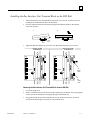
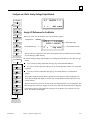
Installing the Bus Interface Unit Terminal Block on the DIN Rail
1.
Tilt the Bus Interface Unit Terminal Block and position it over the rail, as shown below left,
catching the rail behind the tabs in the terminal block.
2.
Pivot the terminal block downward until the spring-loaded DIN rail latches in the terminal
block click into place.
1
2
tabs
3.
DIN
rail
Tighten the DIN rail clamp screw (see below left). Recommended torque is 4 to 6-in/lbs.
Removing the BIU
Terminal Block
Installing the BIU
Terminal Block
Tighten
Loosen
Pry
Upper
latch
Pry
Lower
latch
Removing the Bus Interface Unit Terminal Block from the DIN Rail
GFK-0825F
1.
Loosen the clamp screw.
2.
Insert a small flat-blade screwdriver into the upper latch and pry it outward. Then, pull up gently
on the top of the terminal block to disengage the upper latch from the rail.
3.
Keep gently pulling the top of the terminal block away from the rail. Insert the screwdriver
into the lower latch and pry it outward to free the terminal block.
Chapter 3 Installation
3-7
3
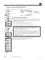
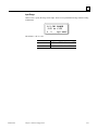
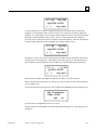
Installing the Cables Between Terminal Blocks
Before installing modules on their terminal blocks, install the connecting cable(s) between terminal
blocks. A short connecting cable, as illustrated below, is supplied with each I/O Terminal Block. A
set of three connecting cables is available as renewal part number IC670CBL001. Optional 21-inch
(0.53 meter) cable is also available (IC670CBL002) (only one 21" cable can be used per Field
Control station).
The illustration below shows cable connection between a Bus Interface Unit terminal block and an
I/O Terminal Block. Make connections between I/O Terminal Blocks in the same manner. The
connectors are keyed to assure proper installation.
Bus Interface
Unit Terminal
Block
Terminal
Block
Connection
Cable
I/O Terminal
Block
Connector for Cable
to Next Device
After installing the cable, be sure it is firmly seated on both connectors.
3-8
Field Control™ Genius® Bus Interface Unit User’s Manual – October 1999
GFK-0825F
3
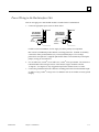
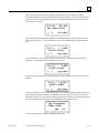
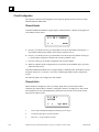
Power Wiring to the Bus Interface Unit
Note: Do not apply power until the BIU module is installed on the Terminal Block.
1.
Connect an appropriate power source as shown below.
Low Voltage
Connections
(IC670GBI002)
High Voltage
Connections
(IC670GBII02)
24 VDC
+
115VAC or
125VDC
For BIU version IC670GBI102, if a DC supply is used the polarity is not important.
BIU version IC670GBI102 provides internal overvoltage protection. Terminal 4 is normally
connected to frame ground (terminal 3) by a factory-installed jumper. If overvoltage
protection is not required or is supplied upstream this feature can be disabled by removing the
jumper, leaving pin 4 unconnected.
2.
Use one AWG #14 (2.1mm2) or two AWG #16 (1.3mm2) wires per terminal. The wires into a
terminal should be the same type and size. Wires must be copper conductors rated for
75 degrees C (167 degrees F) only. Suggested torque for the terminal screws is 9 in/lbs.
3.
Connect the ground terminal to the conductive mounting panel with a 4-inch maximum length
of AWG #14 (avg 2.1mm2) or larger wire. Use hardware such as star washers to ensure ground
integrity.
GFK-0825F
Chapter 3 Installation
3-9
3
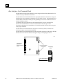
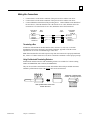
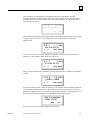
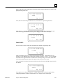
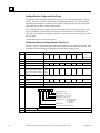
Connecting the Communications Bus
The Bus Interface Unit Terminal Block has a two sets of bus terminals. The terminals in the center
portion of the terminal block are for the main bus cable; they are always used.
The outermost set of bus terminals is for an optional redundant (dual) bus cable. The Bus Interface
Unit Terminal Block has built-in bus switching capability; do not attach a Bus Switching Module in
a dual bus application.
46462
Redundant Bus
Connections
(optional)
Serial 1
Serial 2
Shield In
Shield Out
Main Bus
Connections
Shield Out
Shield In
Serial 2
Serial 1
B1
B2
Bin
Bout
Aout
Ain
A2
A1
Terminals accept one AWG #14 (2.1mm2) or two AWG #14 (avg 2.1mm2 cross section) copper
75 deg. C (167 deg. F) wires. Each terminal can accept solid or stranded wires. The wires on any
terminal should be the same type. The suggested torque is 9 in/lbs (1 Nm).
Bus Cables
Bus connections can be made using standard bus cables (cable specifications for the Genius bus are
detailed in Appendix C. Also see Appendix C for a discussion of the characteristics of the Genius
bus.
When making bus connections, the maximum exposed length of unshielded wires should be two inches
(5cm). For added protection, each shield drain wire should be insulated with spaghetti tubing to prevent
the Shield In and Shield Out wires from touching each other, or the signal wires.
For applications using 150 ohm cables, prefabricated cables are available in 15" (IC660BLC001)
and 36" (IC660BLC003) lengths. These cables terminate in mating connectors that simplify wiring
between I/O blocks. The 36" cable is recommended for Field Control installations.
SHD SHD SER SER
OUT IN
2
1
SHD SHD SER SER
OUT IN
2
1
3-10
Field Control™ Genius® Bus Interface Unit User’s Manual – October 1999
GFK-0825F
3
Making Bus Connections
1.
2.
3.
Connect Serial 1 to the Serial 1 terminals of the previous device and the next device.
Connect Serial 2 to the Serial 2 terminals of the previous device and the next device.
Connect Shield In to Shield Out of the preceding device. Connect Shield Out to Shield In of
the next device. If the Bus Interface Unit is the first device on a bus, Shield In can be left
unconnected. If it is the last device on a bus, Shield Out can be left unconnected.
Terminating
Resistor
Start
of Bus
Serial 1
Serial 2
Shield In
Shield Out
End
of Bus
Terminating
Resistor
Serial 1
Serial 2
Shield In
Shield Out
Terminating a Bus
If either bus will terminate at the Bus Interface Unit, connect a 75, 100, 120, or 150-ohm
terminating resistor across the Serial 1 and Serial 2 terminals. Appendix C lists the correct
impedance to use for each recommended type of bus cable.
Note: If the Bus Interface Unit will be powered up when not connected to a properly-terminated
bus, connect a 75-ohm resistor across its Serial 1 and Serial 2 terminals to assure proper powerup.
Using Prefabricated Terminating Resistors
Prefabricated molded connectors with terminating resistors are available for 75 ohms (catalog
number IC660BLM508) and 150 ohms (IC660BLM506).
They can be used with conventional bus cable and with the cables with pre-molded connectors.
Attach the prefabricated resistor to the female cable end as shown below.
Underside of prefabricated
resistor, showing projection
Slide prefabricated resistor onto
female cable end
GFK-0825F
Chapter 3 Installation
3-11
3
Installing Pre-Molded Bus Cables
Pre-molded cables must be installed in the orientation shown below. The main bus cable exits
toward the power connections. The optional redundant bus cable exits away from the power
connections.
Premolded Cable Positions for
Bus Interface Unit Mounted
with Terminals on Right
Optional
Redundant
Bus
Main Bus
Serial 1
Serial 2
Shield In
Shield Out
Shield Out
Shield In
Serial 2
Serial 1
Serial 1
Serial 2
Shield In
Shield Out
Shield Out
Shield In
Serial 2
Serial 1
Main Bus
Optional
Redundant
Bus
Premolded Cable Positions for
Bus Interface Unit Mounted
with Terminals on Left
Where two prefabricated cable ends meet at the same device, join the male and female ends (see
below).
If a prefabricated cable will be at the end of the bus (requiring termination, as explained), and you
want to use a prefabricated terminating resistor, make the cable installation so that a female
connector will be located at the device where the cable will be terminated.
male
connector
female
connector
male
connector
46492
Mating
connectors
Mating
connectors
female
connector
terminating re
sistor (male)
Connect to
Last Device
3-12
Field Control™ Genius® Bus Interface Unit User’s Manual – October 1999
GFK-0825F
3
Bus Connection for Critical Processes
Bus connections are normally considered permanent. They should never be removed while the bus
is in operation; the resulting unreliable data on the bus could cause hazardous control conditions.
If the bus controls critical processes that cannot be shut down, the Terminal Block can be wired to
the bus via an intermediate connector as shown below.
I
N
O
U
T
SHLD OUT
S2
Shield Out
Shield In
S1
Serial 2
SHLD IN
Serial 1
The connector shown is #A107204NL from Control Design, 458 Crompton Street, Charlotte NC,
28134.
Alternatively, the wire ends can be soldered together before inserting them into the terminals.
When removing the Terminal Block, cover the ends of the wires with tape to prevent shorting the
signal wires to one another or to ground.
Both of these methods allow the Terminal Block to be removed while maintaining data integrity on
the bus.
GFK-0825F
Chapter 3 Installation
3-13
3
Installing the Bus Interface Unit on the Terminal Block
End
View
1.
Before installing a new Bus Interface Unit, remove the cable slot
knockout on the end of the module that will cover the connecting
cable. It can be removed with pliers, or by pressing out from
inside the module housing.
2.
Power to the I/O Station should be OFF.
3.
To install Bus Interface Unit on the terminal block, position the
module so that the cable slot in the module housing is over the
connecting cable. Press the module down firmly.
Cable Slot
Connecting Cable
(cross section)
Caution
Excessive force may damage the equipment.
3.
After placing the Bus Interface Unit onto the terminal block, tighten its screws to secure it.
Maximum recommended torque is 9 in/lbs.
Warnings
Explosion hazard. When in hazardous locations, turn off power before replacing or the BIU.
Personal injury, system malfunction and/or damage to the equipment may occur.
Equipment labeled with reference to Class I, Groups A, B, C, and D, Div. 2 hazardous
locations is suitable for use only in non-hazardous locations or in Class I, Div. 2, Groups A, B,
C, and D locations.
Explosion hazard: Substitution of components may impair suitability for Class I, Division 2.
Removing the Bus Interface Unit from the Terminal Block
Do Not Tilt
1.
Power to the I/O Station should be Off.
2.
Loosen the Bus Interface Unit retaining screws.
Caution
Be sure screws are fully disengaged. Attempting to
remove the module with screw(s) partially engaged may
damage the equipment.
3.
Pull the Bus Interface Unit module straight away from the
Terminal Block.
Caution
Do not tilt the Bus Interface Unit to remove it. Attempting
to remove the Bus Interface Unit at an angle may damage
the equipment.
3-14
Field Control™ Genius® Bus Interface Unit User’s Manual – October 1999
GFK-0825F
3
Removing/Replacing the Bus Interface Unit Fuse
If all the Bus Interface Unit LEDs go off, it may be necessary to replace its fuse. The fuse can be
removed without disturbing any other parts of the station or wiring.
1.
To check the fuse, remove power from the station.
Caution
Avoid touching the exposed wiring on the Terminal Block when removing
the Bus Interface Unit.
Caution
Electrostatic discharge can damage the module when it is not installed on a Terminal Block.
Always observe normal ESD protection practices when handling an un-installed module. Use
of a ground cuff and a grounded floor surface are recommended.
2.
Fully loosen the retaining screws in the Bus Interface Unit and carefully remove it from the
Terminal Block. Do not tilt the module during removal.
3.
Remove the retaining screws from the BIU.
4.
The fuse location is shown below. Visually inspect the fuse to see whether it has blown.
46464
Fuse
5.
To remove the fuse from the holder, carefully pry it upward. Take care not to damage any
components in the module. Place the new fuse in position and press it into the holder.
The fuse should be a 1A, 5x20mm 250VAC slow-blow type. Suitable fuses are: Bussman
#GMC-V-1A and Littelfuse #239 001.
6.
GFK-0825F
Reinstall the Bus Interface Unit on the BIU Terminal Block as described on the previous page.
Chapter 3 Installation
3-15
3
Upgrading the BIU Firmware
Note
The BIU EEPROM stores the configuration of the I/O Station. If you replace the
BIU EEPROM, it will be necessary to reconfigure the I/O Station using a Handheld Monitor.
Follow the steps below to replace the BIU's firmware EEPROM.
Caution
Avoid touching the exposed wiring on the Terminal Block when removing
the Bus Interface Unit.
Caution
Electrostatic discharge can damage the module when it is not installed on a
Terminal Block. Always observe normal ESD protection practices when
handling an un-installed module. Use of a ground cuff and a grounded floor
surface are recommended.
1.
Remove power to the I/O Station.
2.
Fully loosen the retaining screws in the Bus Interface Unit and carefully remove it from the
Terminal Block. Do not tilt the module during removal.
3.
Remove the retaining screws from the BIU.
4.
The firmware EEPROM is located on the 2-board set that also includes the Hand-held Monitor
connector. This set of two boards and their plastic card guide must be removed from the
module housing.
46546
Remove
3-16
Field Control™ Genius® Bus Interface Unit User’s Manual – October 1999
GFK-0825F
3
Note the position of the card guide with respect to the metal housing for reassembly.
46547
card guide
4.
Hold your hand behind the module to retain the board set, and turn the module face up.
5.
Insert a small screwdriver or similar tool into either of the holes from which you previously
removed the module retaining screws. Pry the two halves of the plastic latch inward to free that
side of the card guide. Repeat on the other side.
46548
latch
7.
Remove the dual board set and card guide from the housing.
8.
Replace the EEPROM on the board with the EEPROM containing the new firmware for the
BIU.
9.
Reinsert the board set into the module housing, taking care to align the card guide with the
screw holes in the housing.
10. When the card guide is in position, press downward gently on the back of the card guide to
seat the latches. Check the front of the module to be sure they have seated correctly.
11. Reinstall the Bus Interface Unit on the BIU Terminal Block.
12. Using a Hand-held Monitor version 4.6 or later, reconfigure the I/O Station.
GFK-0825F
Chapter 3 Installation
3-17
Chapter
Operation
4
This chapter explains how a Bus Interface Unit interacts with the modules in its station, how it
stores data, and how it exchanges data with the system host.
GFK-0825F
BIU Data Handling at the I/O Station
The BIU Sweep
BIU Backplane Scan Time
Data Transfer Between the BIU and the Host
Genius Bus Scan Time
Operation of the BIU with a Micro Field Processor
Backing Up Micro Field Processor Outputs
Backing Up BIU Outputs with a Micro Field Processor
4-1
4
BIU Data Handling at the I/O Station
The BIU manages all movement of data within the I/O station and between the I/O station and the
Genius bus. The BIU scans the I/O modules in the station, exchanges data with the host, and can
manage the exchange of data between a Micro Field Processor and other modules in the station. In
addition to its regular I/O scanning capabilities, the BIU can also selectively transfer specific data
groups from one intelligent module in the station to another.
All of the data for the I/O station, whether it is data that is exchanged on the Genius bus or local
data, utilizes the BIU's four I/O data memories.
The BIU has 256 bytes of memory available for each of the four types of data (discrete inputs and
outputs, data types I and Q, and analog inputs and outputs, data types AI and AQ). During BIU
configuration, data for individual modules is assigned to specific areas of this memory.
BIU Memory
Type
Typically Used For
Amount Available Highest Available
in BIU
Reference Address
I
discrete inputs, and status data from
intelligent modules
256 bytes
65535
Q
discrete outputs, and fault clearing for
intelligent modules
256 bytes
65535
AI
analog inputs
256 bytes
9999
AQ
analog outputs
256 bytes
9999
Data can be configured anywhere within the BIU's available memory. If the data will be exchanged
on the network bus, data must be assigned to contiguous memory locations, as explained later.
The following paragraphs describe the types of data the BIU exchanges with conventional I/O
modules and intelligent I/O modules.
4-2
Field Control™ Genius® Bus Interface Unit User’s Manual – October 1999
GFK-0825F
4
I/O Data for Conventional Modules
Conventional I/O modules provide or receive just one type of I/O data (sometimes referred to as
reference data). Normally, this data is assigned to the data types shown below; however, any
module's data can be assigned to any data type in BIU memory.
Type of Module
Type of Data
discrete inputs
analog inputs
discrete outputs
analog outputs
I
AI
Q
AQ
The BIU reads inputs from all conventional input modules and sends outputs to all conventional
output modules during every “sweep" of operations.
Field Control Station
Bus Interface Unit
I
Q
AI
AQ
Reference Data
Is Transferred
Each BIU Sweep
Conventional
Discrete Input
Modules
Conventional
Analog Input
Modules
Conventional
Discrete Output
Modules
Conventional
Analog Output
Modules
I/O Data, Status Data, and Control Data for Intelligent Modules
“Intelligent" modules such as the Micro Field Processor, Thermocouple, RTD, and other intelligent
modules provide and receive multiple types of I/O data. (This data is sometimes called reference
parameters). For example, the 16 Point Grouped Analog Input Module provides and receives the
following types of data:
16 (two-byte) analog inputs for channel input data. This data is normally configured to use AI
memory, although that is not required.
88 bits of discrete inputs (I) for module and channel status data.
16 bits of discrete outputs (Q) for fault-clearing commands to the module.
Some intelligent modules use all four available data types: discrete inputs and outputs and analog
inputs and outputs.
The BIU reads input and status data and sends output and command data to intelligent module
during every "sweep" of BIU operations.
Field Control Station
Bus Interface Unit
I
Q
AI
AQ
intelligent
Analog Input
Module
Reference Parameters are
Transferred Each BIU Sweep
GFK-0825F
Chapter 4 Operation
4-3
4
Group Data for Intelligent Modules
Intelligent modules can also be configured for "Group" data transfer with the BIU or with other
intelligent devices in the same Field Control station. A data group is a selected set of data that the
BIU transfers from one location to another location in the station. The BIU can transfer the group
data during every sweep of its operations, or only during specified sweeps. This ability to "skip"
group data transfers during certain sweeps makes it possible to shorten the BIU's overall sweep
time.
Up to 16 groups can be set up for an I/O station.
A group contains data from only one module to only one module. Either module may be an I/O
module, a Micro Field Processor, or the Bus Interface Unit.
Field Control Station
Bus Interface Unit
I
Micro Field
Processor
I
Q
Q
AI
AQ
AI
AQ
Intelligent I/O
Module
I
Group Data is
Transferred
During Selected
Sweeps Only
Q
AI
AQ
A group can consist of a combination of I, Q, AI, and/or AQ data.
For each data type, a starting offset and length can be specified. It is not necessary to move all
of a module's data.
The data does not need to be moved during each BIU sweep.
Selective Sweep
For group data only, the BIU can move the data on each sweep, or on any combination of up to 16
sweeps. The selection of sweeps is easily made when configuring the group.
Examples
Appendix D includes examples of how data might be configured for group moves.
4-4
Field Control™ Genius® Bus Interface Unit User’s Manual – October 1999
GFK-0825F
4
The BIU Sweep
46543
1
Read all inputs from conventional
discrete and analog input modules
The "sweep" of the Bus Interface Unit is the sequence of actions it executes
repeatedly as long as the module is receiving power.
1 BIU Reads Inputs from Conventional Modules
2
Read all reference parameter inputs from
•smart" modules
3
*
Read all group data moves whose
destination is the BIU, except groups
whose source is a Synchronization module
4
*
Send Group Data moves
to a Synchronization module
5
Send outputs from BIU tables
to Synchronization modules
6
Move all inputs within BIU network map
from BIU tables to the Genius
communications buffers
7
Move all outputs within BIU network
map from the Genius communications
buffers to the BIU internal tables
BIU Waits if
MFP is busy
The BIU first reads inputs from conventional I/O modules. The BIU
combines input data with any corresponding forced data and puts it in its
input data tables at the configured locations. If a module fails to supply
valid input data, the BIU generates a fault report to the host. If the module is
configured for Hold Last State, the BIU holds the module's data at its last
valid state. If the module is configured to default its inputs, the BIU places
zeros in the module's assigned references for all inputs that are not forced.
Any forced inputs retain their forced states.
For inputs from conventional analog modules, the BIU also performs
scaling, calibration, alarm checking, and range checking.
2 BIU Reads All Input Reference Parameters
Next, the BIU reads all configured discrete and analog reference parameters
from "intelligent" modules (including an MFP). If a module fails to supply
valid input data, the BIU generates a fault report to the host. If the module
is configured for Hold Last State, the BIU holds the module's data at its last
valid state. If the module is configured to default its inputs, the BIU places
zeros in the module's assigned references for all inputs that are not forced.
Any forced inputs retain their forced states.
3 BIU Reads Group Data Whose Destination is BIU
8
Read all reference input parameters from
a Synchronization module
*
9
Read all group data to the BIU
from a Synchronization module
10
Send all outputs to conventional modules
11
Send all reference parameter outputs to
•smart" modules, but not to
a Synchronization module
Next, the BIU reads the input group data for which the destination is slot 0
(the BIU) from all intelligent modules except a Synchronization module.
The BIU reads only the group inputs that have been configured to be read
during that sweep. If a module fails to supply valid input data, the BIU
generates a fault report to the host. If the module is configured for Hold
Last State, the BIU holds the module's data at its last valid state. If the
module is configured to default its inputs, the BIU places zeros in the
module's assigned references for all inputs that are not forced. Any forced
inputs retain their forced states.
4 BIU Sends Group Data to Synchronization Module
12
*
Send all group data to all •smart"
modules except Synchronization module
...
Background Tasks
*
Group Data is moved only
during its configured BIU sweeps.
The tasks shown in shaded boxes are performed
only if the I/O Station includes a Synchronization
module. The Synchronization module is usually a
Micro FIeld Processor.
GFK-0825F
Chapter 4 Operation
If a module (usually a Micro Field Processor) has been configured as a
Synchronization module, the BIU next transfers group data assigned to be
sent to it during that sweep.
5 BIU Sends Reference Parameters to a Synchronization Module
If a module has been configured as a Synchronization module, the BIU next
sends its reference parameter data from BIU tables.
4-5
4
6 Move Input Data to the Communications Buffer
The BIU then moves all current discrete and analog input values presently in its network map into a
memory buffer, in preparation for transmitting them on the Genius bus.
7 Move Output Data from the Communications Buffer
After moving the inputs into the communications buffer, the BIU moves newly-received output
data from the communications buffer. It combines this data with any existing forced discrete output
states and analog values and places the combined data in its discrete (%Q) and analog (%AQ)
output memories, as defined in the BIU I/O map.
If the BIU is not receiving outputs from the bus, it sets mapped output references for conventional
modules to their default/hold last state conditions, then forces them. For any intelligent module set
up for defaults, the BIU sets output table references to their forced state or value, or to zero.
8 Move Reference Parameters from a Synchronization Module to the BIU
If a module has been configured as a Synchronization module, the BIU next moves all configured
reference parameter data from the module to the BIU's internal memory tables, then applies any
forces. If the Synchronization module is busy, the BIU waits then retries. If the BIU is unable to
move the data after five seconds, it sets its own corresponding memory locations to zero or holds
its last states, as configured for the Synchronization module.
9 Move Group Data from Synchronization Module to BIU
If a module has been configured as a Synchronization module, the BIU moves all its defined group
data to the BIU's internal tables, then applies any forces. If the BIU is unable to read the specified
data, it generates a fault report, and defaults the data to 0 or holds its last states, depending on the
module's configuration. If any of the data items are presently forced, those forces are retained.
10 Send Outputs to Conventional Modules
The BIU next sends output data to conventional output modules in the I/O station. Discrete output
modules automatically echo the received outputs back to the BIU. If a module fails to echo its
outputs the BIU generates a fault report for that module. If the module is configured for output
defaulting, the BIU attempts to set outputs to their default states. This is not always possible,
depending on the nature of the problem.
For conventional analog modules, the BIU converts data from the selected scaled units and
performs range checking before sending the outputs.
11 Send Reference Parameters to Intelligent Modules
Next, the BIU sends reference parameter data from its tables to intelligent modules except a
Synchronization module. If the BIU is unable to contact a module it generates a fault report.
12 Move Group Data to Intelligent Modules
The BIU moves group data from intelligent modules or from its own internal memories to any
intelligent modules, except a Synchronization module, that is configured to receive data during that
sweep. If the move fails, a fault is generated.
Background Tasks
After performing all the data transfers described above, the BIU performs a sequence of
background tasks such as fault processing, scanning module IDs, and testing memory.
4-6
Field Control™ Genius® Bus Interface Unit User’s Manual – October 1999
GFK-0825F
4
BIU Backplane Scan Time
The backplane scan time for the Genius BIU depends on: the type and number of modules present
in the Field Control station, the scan time of the Genius bus, and the number and type of Group
Data Move definitions.
Shorter Genius bus scan times typically impose more overhead on the BIU, increasing backplane
times. Longer Genius bus scan times tend to reduce the overall load to the BIU and thus slightly
decrease backplane scan times.
An estimate of backplane scan times can be found using this equation:.
Backplane scan time (mS) = ( I/O X ( 0.8 + ( 2.25 / Genius Bus Scan ) ) ) + Groups + MFP + 1
In the equation:
I/O
=
+
+
+
+
0.150 X number of conventional module discrete (I and Q) bytes
0.500 X number of conventional module analog (AI and AQ) words
0.090 X number of intelligent module discrete (I and Q) bytes
0.150 X number of intelligent module analog (AI and AQ) words
0.500 X number of I/O modules
Groups
=
+
+
.0.015 X number of bytes, internal BIU table moves
0.093 X number of bytes, BIU / module moves
0.175 X number of bytes, module to module moves
MFP
=
MFP logic sweep time (if MFP synchronized)
Example 1:
Four modules, no Group Data Moves. Genius bus speed is 47mS.
Slot
Time per
word / byte
Total Time
in mS
16 words AI
.150
2.40
11 bytes I
.090
0.99
2 bytes Q
.090
0.18
2
Conventional discrete output module 2 bytes Q
.150
0.30
3
Conventional analog output module
4 words AQ
.500
2.00
4
RTD Input module
4 words AI
.150
0.60
4 bytes I
.090
0.36
1 byte Q
.090
0.09
4 words AQ
.150
0.30
.500
2.00
1
+
Module
16-Point Grouped Analog Input
Module (IC670ALG240)
Data per Module
number of modules ( 4 )
=
Total I/O
9.52 X ( 0.8 X ( 2.25 / 47 mS ) )
8.07 mS
+
Groups (none)
0.00
+
Micro Field Processor (none)
0.00
+
1.00
Estimated backplane scan time
GFK-0825F
9.52
Chapter 4 Operation
9.07 mS
4-7
4
Example 2:
Five modules, one Group Data Move. Genius bus speed is 26mS.
Slot
Module
1
Conventional analog output module
2
Conventional analog input module
3
Time per
word / byte
Total Time
in mS
4 words AQ
.500
2.00
8 words AI
.500
4.00
Conventional discrete output module 2 bytes Q
.150
0.30
4
Conventional discrete input module
2 bytes I
.150
0.30
5
16-Point Grouped Analog Input
Module (IC670ALG240)
16 words AI
.150
2.40
11 bytes I
.090
0.99
2 bytes Q
.090
0.18
.500
2.50
+
Data per Module
number of modules ( 5 )
=
Total I/O
12.67 X ( 0.8 X ( 2.25 / 26 mS ) )
+
Groups
+
Micro Field Processor (none)
64 bytes: Internal BIU
table move
11.23 mS
0.96
0.00
+
1.00
Estimated backplane scan time
4-8
12.67
Field Control™ Genius® Bus Interface Unit User’s Manual – October 1999
13.19 mS
GFK-0825F
4
Data Transfer Between the BIU and the Host
Each bus scan, a Bus Interface Unit exchanges the following data with the host:
It sends an input message with up to 128 bytes of discrete and/or analog inputs.
It receives an output message with up to 128 bytes of discrete and/or analog outputs.
The exact length of these messages is determined by the network I/O map configured for the Bus
Interface Unit.
Data in the BIU's Network (Bus) Map
As mentioned previously, the BIU has 256 bytes of memory available for each of the four types of
data (discrete and analog inputs and outputs: I, Q, AI, and AQ). For each data type, up to half (128)
of the 256 bytes can be used for the data that will be exchanged on the Genius bus. During BIU
configuration, starting addresses and lengths are set up for each of the BIU's four types of I/O
memory. These addresses and lengths define the BIU's network I/O map. The data from each table
(I, AI, Q, and AQ) must be contiguous.
BIU Memory Type
Designation
Amount Available in BIU
Maximum Length for
Network Map
I
Q
AI
AQ
256 bytes
256 bytes
256 bytes
256 bytes
up to 1024 contiguous bits
up to 1024 contiguous bits
up to 64 contiguous words
up to 64 contiguous words
Note that although it is possible to configure up to 128 bytes of memory in the network map for
each data type, the maximum amount that can be included in the map is a total of 128 bytes of
inputs (I plus AI) and 128 bytes of outputs (Q plus AQ).
Data to be exchanged on the bus must be configured to use references within the network map
configured for the BIU. Data of individual I/O modules may be configured anywhere within
available memory. It is possible to have inputs or outputs within the I/O station that are not
exchanged on the Genius bus-that is, data that is completely local to the I/O station. For example,
the I/O station might include a Micro Field Processor performing local data processing.
Communications on the Genius Bus
After a Bus Interface Unit completes a successful login with the host, it begins sending input data
on the bus and accepting output data from the bus. The BIU communicates on the bus repetitively
and asynchronously. When the BIU receives the Genius bus communications token, it sends the
most recent data from the configured portion of its I and AI memories on the bus. As mentioned,
these memories are repeatedly updated whenever the Bus Interface Unit scans the input modules in
the station.
The Bus Interface Unit receives new outputs from the host when the host's bus controller has the
communications token. It places these outputs into the configured portion of its Q and AQ output
tables. These outputs are then passed to the devices in the station on the BIU's next I/O scan.
GFK-0825F
Chapter 4 Operation
4-9
4
Input Data Sent by the Bus Interface Unit
When the Bus Interface Unit takes its turn on the bus, it sends one input data message containing
the latest values for all configured discrete inputs followed by all configured analog inputs.
Because they are broadcast (like all Genius inputs), they can be obtained by any Bus Controller on
the bus.
Input Data Message
(up to 128 bytes)
discrete inputs
analog inputs
To CPU
Configured I Length
I starting reference data
Configured AI Length
AI starting reference data
The data lengths are equal to the configured lengths of I and AI data selected for the Bus Interface
Unit (regardless of the host CPU type or the actual amount of output data needed for the modules
physically present in the station). Either length may be zero.
The discrete inputs appear in the input message in the same sequence as their assigned input
references. Each discrete input module occupies one byte per eight circuits.
The analog inputs are also in the same sequence as their assigned input references. Each analog
input module occupies two bytes (one word) for each analog channel.
The Bus Interface Unit sends this data from its internal I and AI memories, beginning at the start
locations selected during station configuration.
Input Defaults
When configuring input modules, either a default state or hold last state can be selected. If an input
module is removed or fails to operate correctly, the chosen state is substituted for actual input data.
A diagnostic message is provided to indicate loss of module. Forced input data is not affected.
I/O Data Handling by Host
How the host handles input data from the Bus Interface Unit depends on the host type:
4-10
A Series 90-70 PLC places the data in the %I and %AI references selected during PLC
configuration. These must be the same references selected during Bus Interface Unit
configuration.
A Series Six or Series Five PLC places the data into I/O table or register memory. A
beginning address in Series Six or Series Five I/O Table memory can be entered during station
configuration.
A host computer with a PCIM module places the data into the input table segment that
corresponds to the serial bus address (Device Number) of the Bus Interface Unit.
Field Control™ Genius® Bus Interface Unit User’s Manual – October 1999
GFK-0825F
4
Outputs from the Host to the BIU
Each time the host's Bus Controller has the bus communications token, it sends any outputs it has
received from the CPU to the devices on the bus. Outputs for the Bus Interface Unit are sent in one
output data message, with all configured discrete outputs followed by all configured analog
outputs.
Output Data Message
(up to 128 bytes)
discrete outputs
To
Station
analog outputs
Configured Q Length
Configured AQ Length
Q starting reference data
AQ starting reference data
The data lengths are equal to the configured lengths of Q and AQ data selected for the Bus
Interface Unit (regardless of the host CPU type or the actual amount of output data needed for the
modules physically present in the station). Either length may be zero.
Output Data Format
The output data format shown above is required by the BIU.
When generating the output data message, a Series 90-70 Bus Controller automatically places the
Q data ahead of the AQ data. Other types of host must send an output message consisting of the
correct number of bytes of discrete output data followed by the correct number of bytes of analog
output data.
As soon as new output data is received, the Bus Interface Unit checks it to be sure the data is errorfree and of the correct length. The length must match the combined lengths of the discrete output
data and analog output data that have been configured for the Bus Interface Unit's network I/O
map. After verifying the accuracy of the data, the Bus Interface Unit puts the data in its Q and Q
tables, and begins passing it to the output modules in the station. Each discrete output module
receives one byte of data for each eight circuits. Each analog output module receives two bytes
(one word) for each analog channel.
Output Defaults
On powerup, all outputs go to their programmed default state, except outputs which had previously
been forced--they go immediately to their forced state or value.
If CPU communications are lost for 3 bus scans, all outputs that are not presently forced will either
default or hold their last state, as configured.
Conventional I/O modules can have a configured output default value. Intelligent modules default
outputs are always zero.
GFK-0825F
Chapter 4 Operation
4-11
4
Genius Bus Scan Time
The Genius bus scan time is dependent on the number of devices and amount of data traffic on the
bus. The bus scan time may vary from 3-400mS, but 20-30mS is typical. Bus Controllers impose a
minimum Genius bus scan time of 3mS. Therefore, Genius bus scan time can never be less than
3mS. The Genius bus scan time contribution for Field Control station depends on its I/O data
usage. The table below shows the scan time contribution, at each baud rate, for stations with a total
of 16, 32, 64, 128, and 256 bytes, when the Bus Interface Unit receives outputs from only one bus
controller at a time.
To find the exact scan time contribution for a station, follow the procedure below.
Total Amount of Input and
Output Data for
Field Control Station
16 bytes
32 bytes
64 bytes
128 bytes
256 bytes (fully-loaded)
Contribution time in mS at each baud rate
153.6 Kb
std
2.09
3.24
5.52
10.10
19.25
153.6 Kb
ext
2.16
3.31
5.60
10.17
19.32
76.8 Kb
38.4 Kb
3.83
6.12
10.69
19.85
38.15
7.16
11.74
20.89
39.20
75.80
Procedure for Estimating Bus Scan Time for a Field Control Station
1.
Find the total number of input bytes and output bytes. (Each analog channels is 2 bytes. Eight
discrete points are one byte).
number of input bytes
number of output bytes
total bytes
2.
= ________
= ________
= ________
With this total, calculate a scan time contribution using the formula below that corresponds to
the Genius bus baud rate.
Formula for 153.6 Kbaud Standard:
0.943mS + (0.0715 x total bytes)
= ________ mS
Formula for 153.6 Kbaud Extended:
1.015mS + (0.0715 x total bytes)
= ________ mS
Formula for 76.8 Kbaud:
1.538mS + (0.143 x total bytes)
= ________ mS
Formula for 38.4 Kbaud:
2.583mS + (0.286 x total bytes)
= ________ mS
Other devices on the bus, including the Bus Controller, Hand-held Monitor, and I/O blocks also
add to the bus scan time. The Genius I/O System Manual (Volume 1) shows how to calculate
overall bus scan time for all of the devices on a bus. Remember that the Genius bus scan time can
never be less than the 3mS minimum enforced by the bus controller.
4-12
Field Control™ Genius® Bus Interface Unit User’s Manual – October 1999
GFK-0825F
4
Throughput
If an output in the station is tied to an input in the same station, the output changes state (or value,
in the case of an analog output module) within a few milliseconds of the new output being sent
from the bus controller to the Bus Interface Unit. (To guarantee that an output changes state, that
state must be present for at least one BIU sweep time or bus scan time, whichever is greater.)
The input which is tied to the output responds as soon as any load-effects have settled out and input
filtering is completed. This may occur as soon as the Bus Interface Unit's next I/O scan.
If the host is a PLC, an input must be present for at least one PLC sweep time plus one Genius bus
scan time plus one BIU sweep time to guarantee its detection by the PLC. If the input changes
state only briefly, and then changes again before the input data is sent on the bus, the interim state
may be overwritten in the Bus Interface Unit's internal memory by some new input state or value
before it can be sent.
GFK-0825F
Chapter 4 Operation
4-13
4
Operation of the BIU with a Micro Field Processor
The Micro Field Processor (MFP) is a specialized Micro PLC that provides local input/output logic
within a Field Control I/O station. The MFP itself does not perform an I/O scan; that function is
performed by the BIU.
MFP and BIU Synchronization
Automatic operation of the Micro Field Processor must be synchronized with that of the BIU.
Synchronization between the MFP and the BIU occurs at the following points:
1.
The MFP waits for group data from the BIU.
2.
The MFP waits for its input reference parameter data (see page for a discussion of reference
parameter data) from the BIU. After receiving the reference parameter data from the BIU, the
MFP solves its logic program.
3.
After solving its logic program, the MFP waits for the BIU to request its output reference
parameter data. Or, if the MFP is still busy, the BIU waits for the Micro Field Processor to
finish solving its logic.
4.
The MFP waits for the BIU to request any group data from the MFP.
The diagram on the next page shows the basic points of synchronization between a BIU and an
MFP. The Micro Field Processor always performs housekeeping and programmer window
functions regardless of the combination of BIU and MFP modes.
MFP I/O References
The MFP itself has the following configurable references:
I001
Q001
AI001
AQ001
to
to
to
to
I512
Q512
AI128
AQ128
References used by the host may map to these MFP references, although that is not necessary.
Appendix D gives examples of I/O reference assignments.
MFP Operating Modes
In the Standard Program Sweep mode, the Micro Field Processor executes each sweep as quickly
as possible with a varying amount of time consumed each sweep.
In the Constant Sweep Time mode, each sweep consumes the same amount of time. This time is
configurable to be from 5 to 200 milliseconds.
When the MFP is in Stop mode, the application program is not executed. In this mode, it is
possible to choose whether or not the I/O is scanned (internally, by the MFP) and whether
communications with the programmer will continue.
If the BIU requests data from the Micro Field Processor while the MFP is in Stop Fault mode, the
requested data will either be defaulted or held in its last state, depending on the configuration of the MFP.
In Stop-No I/O mode, the MFP updates its internal I/AI tables with data received from the BIU,
and sends zeros for all data (reference or group) to the BIU.
4-14
Field Control™ Genius® Bus Interface Unit User’s Manual – October 1999
GFK-0825F
4
Synchronous Operation of a BIU and a Micro Field Processor
Bus Interface Unit
1
Micro Field Processor
Read all inputs from conventional
discrete and analog input modules
MFP Waits
2
3
4
Read all reference parameter inputs from
“smart” modules
*
*
5
MFP receives Group Data
from the BIU
Read all group data moves whose
destination is the BIU, except groups
whose source is a Synchronization module
MFP Waits
Send Group Data moves
to a Synchronization module
Send outputs from BIU
to Synchronization modules
6
Move all inputs within BIU network map
from BIU tables to the Genius
communications buffers
7
Move all outputs within BIU network
map from the Genius communications
buffers to the BIU internal tables
MFP receives data from the BIU
and places the data in its input tables
MFP “BUSY”
MFP places received data into its
configured memory locations
MFP solves its program logic
utilizing newly-received data
MFP updates its
configured memory locations
BIU Waits if
MFP is busy
8
9
Read all reference input parameters from
a Synchronization module
*
MFP provides data from its
output tables to the BIU
Read all group data to the BIU
from a Synchronization module
10
Send all outputs to conventional modules
MFP Waits
11
Send all reference parameter outputs to
“smart” modules, but not to
a Synchronization module
MFP provides group data
to the BIU
12
*
Send all group data to all “smart”
modules except a Synchronizarion module
...
Background Tasks
GFK-0825F
MFP Waits
Chapter 4 Operation
The tasks shown in shaded boxes are
performed only if the I/O Station includes a
Synchronization module. The Synchronization
module is usually a Micro FIeld Processor.
*
Group Data is moved only
during its configured BIU sweeps.
4-15
4
Overview of Synchronous Operation
The following diagram and table show how data is handled during synchronous operation.
BIU
Tables
1. Inputs
I
Discrete
Inputs
2. All inputs
Conventional
Input
Module
3. Groups
3.
6. to
network
AI
Analog
Inputs
4. Groups
5. All outputs
Genius
Network
7. from
network
Q
Discrete
Outputs
AQ
Analog
Outputs
4.
4.
8. All inputs
9. Groups
10. Outputs
Micro
Field
Processor
Smart
Module
Conventional
Output
Module
11. All outputs
12. Groups
12.
12.
Sweep
Step
Forces, if
mapped
No Network
Cannot Read
Module
1
Inputs from conventional modules
yes
-
defaults
2
All inputs from intelligent modules
yes
-
defaults
3
Groups not from MFP: to BIU tables
yes
-
defaults
4
Groups to MFP
yes
-
-
5
All outputs to MFP (starts solution)
-
-
-
6
Move to network
-
n/a
n/a
7
Move from network
yes
n/a
n/a
8
All inputs from MFP (gets solution)
yes
-
defaults
9
Groups from MFP to BIU tables
yes
-
defaults
10
Outputs to conventional modules
-
defaults at step 7
-
11
All outputs to intelligent modules
-
defaults at step 7
-
12
Groups to intelligent modules
-
defaults at step 7
defaults
Data displayed on HHM
-
-
-
(13)
4-16
Action
Field Control™ Genius® Bus Interface Unit User’s Manual – October 1999
GFK-0825F
4
Backing Up Micro Field Processor Outputs
The network can back up outputs normally controlled by the Micro Field Processor if the MFP fails
or goes into Stop Faulted mode.
To create this backup capability for one or more output modules, do the following:
1.
Configure the module outputs to lie within both the BIU's Network Map and the MFP's I/O
map.
For example:
Output References
Q00001-Q00016
Network
Map
Bus Interface Unit Outputs
Q00001 - Q00128
Q00017-Q00128
Q00001-Q00016
Micro Field Processor Outputs
Q00001 - Q00128
Q00017-Q00128
Module Outputs
Q00001 - Q00016
46738
2.
GFK-0825F
Configure Hold Last State (not Default) for the MFP output table.
Chapter 4 Operation
4-17
4
How the Network Backs Up MFP Outputs
This technique works because of the synchronization between the operations of the Bus Interface
Unit and the Micro Field Processor. The diagram below shows details of the BIU/MFP
synchronization process. The numbers on the left side are the same as the numbers on the
synchronization diagram.
Bus Interface Unit
7
Micro Field Processor
Move all outputs within BIU network
map from the Genius communications
buffers to the BIU internal tables
BIU Waits if
MFP is busy
8
Read all reference input parameters from
a Synchronization module
MFP provides data
to BIU
10
Send all outputs to conventional modules
The Bus Interface Unit receives output data for the backed-up output module(s) from the Genius
bus (step 7). In step 8, the BIU receives data from the Micro Field Processor. Any data with the
same reference assignments overwrites the data already received from the bus. When the BIU sends
outputs to I/O modules (step 10), it sends the most recent contents of the output references. If the
MFP has not provided fresh output data (for example, if the MFP has stopped communicating with
the BIU), the outputs from the network are sent to the modules instead. Note that this will not work
if MFP outputs are configured to default instead of Hold Last State, because selecting default
causes the BIU to write default values into the output references at step 8.
4-18
Field Control™ Genius® Bus Interface Unit User’s Manual – October 1999
GFK-0825F
4
Backing Up BIU Outputs with a Micro Field Processor
The Micro Field Processor can take over control of outputs normally provided from the network by
the Bus Interface Unit, if those outputs become unavailable. This technique requires the addition of
ladder logic to the application program.
To create this backup capability for one or more modules, do the following:
1.
Configure the module outputs to the Bus Interface Unit outside of the BIU's network map (that
is, the data exchanged with the bus), but within the I/O range of the MFP.
For example:
Network
Map
Q00001-Q00024
(BIU) References Assigned
to Module Outputs
Q00025-Q00040
(BIU) References Assigned
to Micro Field Processor
Q00001-Q00024
Q00025-Q00040
Q00041-Q00128
Module Outputs
Q00025-Q00040
2.
Create variables to monitor the presence of network outputs, BIU outputs, and to serve as a
heartbeat to verify the presence of the network.
For the example, the variables are:
VARIABLE DECLARATION TABLE
3.
GFK-0825F
REFERENCE
NICKNAME
REFERENCE DESCRIPTION
I00001
I00017
Q00001
NETOUTS
NETPRES
STOUTS
Network outputs
Network presence status
Station outputs
Add ladder logic like the following example to the application program.
Chapter 4 Operation
4-19
4
Example Ladder Logic
[
BLOCK DECLARATIONS
]
[ START OF PROGRAM LOGIC ]
(***********************************************************************
(*Input 17 comes from the network and is always ON while the network is
(*sending outputs to the Field Control Station. The MFP is set to defaul
(*its received data if the network disappears. Therefore when the networ
(*disappears Input 17 will be OFF. Input 17 is a heartbeat detecting the
(*presence of network outputs.
*)
(*When %I17 is ON send all data received from the netrork to the output
(*table to allow the network to control outputs on the station. *)
<<RUNG 6 STEP #0003>>
NETPRES
%I0017
MOVE_
INT
STOUTS
NETOUTS
%I0001 IN Q %Q0001
LEN
00001
(***********************************************************************
(*When %I17 is OFF the network is not present, allow the MFP to control
(*what data goes to the output table to control outputs on the station.
(***********************************************************************
<<RUNG 8 STEP #0006>>
NETPRES
%I0017
MOVE_
INT
ADD_
INT
%R0001
I1 Q %R0001
CONST
+00001
I2
%R0001
STOUTS
IN Q %Q0001
LEN
00001
<<RUNG 9 STEP #0009>>
ALW_ON
%S0007
EQ_
INT
%R0001
I1 Q
CONST
+32767
I2
[
4-20
MOVE_
INT
CONST IN Q %R0001
+00000 LEN
00001
END OF PROGRAM LOGIC
]
Field Control™ Genius® Bus Interface Unit User’s Manual – October 1999
GFK-0825F
Chapter
Station Configuration
5
This chapter explains how to configure a Bus Interface Unit and the I/O modules in a station using
a Hand-held Monitor. HHM version 4.6 (IC660HHM501J) or later is required. Note that the BIU
and I/O modules can also be configured via datagrams from the host. Datagram formats are
detailed in chapter 8.
Setting up the serial bus address and baud rate
Special instructions for Series 90-70 PLC systems
Set up the Hand-held Monitor
Display the configuration menu
Genius configuration
•
Select the baud rate
•
Select the serial bus address for the Bus Interface Unit
•
Select a Series Six or Series Five PLC reference address
•
Configure fault reporting
•
Configure Genius bus redundancy
•
Configure CPU redundancy
•
Select configuration protection
•
Reference address configuration
Module Configuration
• Read a module configuration
• Delete or edit an existing module configuration
• Select a module type
• Configure specific I/O modules.
• Configure a Micro Field Processor
For Additional Information, Also See:
The Hand-held Monitor datasheet for basic operating instructions.
The programming/setup instructions for the system host. The instructions in this chapter are for
local configuration of the BIU and the modules in the I/O station. The system host must also be
configured appropriately to exchange information with the BIU. If the host is a Series 90-70 PLC,
with Logicmaster 90 software release 5.0 or earlier the Genius Bus Interface Unit must be
configured as a "Generic I/O" device.
GFK-0825F
5-1
5
Configuring the Serial Bus Address and Baud Rate
Before a Bus Interface Unit can communicate on the Genius bus, its serial bus address must be
configured. That means if you install a Bus Interface Unit and power it up BEFORE configuring its
serial bus address, it does not communicate on the bus. When you subsequently configure the serial
bus address, the Bus Interface Unit begins communicating on the bus immediately. The baud rate
must be set first in order to configure the BIU online. See the instructions for setting on the Handheld Monitor on the next page.
Special Instructions for Series 90-70 PLC Systems
Assigning the serial bus address is the first configuration step, prior to assignment of the network
map for the Bus Interface Unit. So when the Bus Interface Unit starts communicating, its network
map has not yet been assigned. That causes the Series 90-70 PLC to generate CONFIGURATION
MISMATCH faults. One such fault appears for each non-matching data type and length.
Depending on the PLC's own configuration, CONFIGURATION MISMATCH faults may be either
diagnostic only, or “fatal" (shutting down the system).
To avoid problems, you can do either of the following (method A is preferred):
A. Check the PLC configuration to determine whether CONFIGURATION MISMATCH is set up
as a fatal fault. If it is, powering up the bus and Bus Interface Unit then assigning a serial bus
address will cause a fatal error and shut down the PLC.
•
If CONFIGURATION MISMATCH is a diagnostic fault, you can install the Bus Interface
Unit on the bus and power it up before configuring its serial bus address.
The Bus Interface Unit will start communicating immediately, generating
CONFIGURATION MISMATCH faults. Complete the configuration, ignoring the faults
temporarily. When you complete the Bus Interface Unit configuration, the Bus Interface
Unit drops off the bus briefly, generating a LOSS OF DEVICE fault. When it returns, an
ADDITION OF DEVICE diagnostic appears. If no new mismatch faults occur after the
Bus Interface Unit comes back on the bus (check the timestamp on the faults), the I/O
.maps match in the PLC and in the Bus Interface Unit.
•
If CONFIGURATION MISMATCH is a fatal fault, configure the Bus Interface Unit's
serial bus address and I/O map offline, before installing the Bus Interface Unit. HHM
setup instructions for offline configuration are on the next page. When you then install and
power up the Bus Interface Unit, CONFIGURATION MISMATCH faults will not be
generated. You can complete the rest of the configuration after installation and powerup, if
you prefer.
B. Take the BIU off the bus prior to configuring the Bus Interface Unit. Configure the Bus
Interface Unit baud rate, serial bus address and network map while the BIU is off the bus.
5-2
Field Control™ Genius® Bus Interface Unit User’s Manual – October 1999
GFK-0825F
5
Set Up the Hand-held Monitor
1. If the Bus Interface Unit is connected to an operating bus, the Hand-held Monitor must
be the ONLY Hand-held Monitor plugged into any device on the bus.
If the Bus Interface Unit is NOT presently connected to a properly-terminated Genius bus,
install a 75 Ohm terminating resistor across the Main Bus Serial 1 and Serial 2 terminals on the
Bus Interface Unit Terminal Block. The resistor is needed only for off-line communications
between the HHM and the Bus Interface Unit; it should be removed prior to bus installation
(unless the BIU Terminal Block is the last device on the bus).
2. Begin with the HHM turned off. Attach it to the connector on the Bus Interface Unit.
GENIUS
mon
HandHeldMonitor
GE Fanuc
cfg
F1
F2
F3
F4
7
8
9
Home
4
5
6
Yu
Men
1
2
3
Clear
+
-
0
n
D O
Off
3. Turn the Hand-held Monitor on. Adjust its baud rate if necessary.
Previously unconfigured factory-shipped modules operate at 153.6 Kbaud standard. You
should be aware of the operating baud rate before trying to communicate with the Bus
Interface Unit, and the Hand-held Monitor's baud rate should be set correspondingly. After
HHM powerup and setup, the Home menu appears.
F1:HHM UTILITIES
F2:ANALYZE
F3:CONFIGURATION
F4:DEVICE MEMORY
If the message FUNCTION DISABLED appears during configuration, the corresponding HHM
option has been disabled. To continue, it will be necessary to change HHM options in the HHM
Utilities menu. If the message CONFIG PROTECTED appears, the Bus Interface Unit
configuration has been protected. To continue, it will be necessary to "unprotect" the
configuration.
GFK-0825F
Chapter 5 Station Configuration
5-3
5
Create a New Configuration
If the Bus Interface Unit has already had its Serial Bus Address configured, go to the instructions
on the next page.
If the Bus Interface Unit has not been assigned a Serial Bus Address, select F3 (Configuration)
from the previous menu. The configuration Main Menu appears:
F1:PROG BLOCK ID
F2:CONFIG BLOCK
F3:COPY CONFIG
F4:
Select Program Block ID (F1).
Assigning a Serial Bus Address to a New BIU
The first step in configuring a new Bus Interface Unit is to assign its Serial Bus Address (block
number) on the Program Block ID screen. There are 32 available addresses (from 0 to 31) on a
bus. One is needed for the Hand-held Monitor; typically, this is 0. Another is needed for the Bus
Controller. Typically, this is 31 (30 or 31 for redundancy systems). A Bus Interface Unit is
usually assigned a Serial Bus Address from 1 to 29 or 30. Duplicate Serial Bus Addresses disrupt
communications and are not permitted.
PROG BLOCK ID
I/O
???
BLOCK NO. ?
ref blk
nxt
1.
Press F2 (Block). Then, enter the Device Number (1-30). For example:
PROG BLOCK ID
I/O
???
BLOCK NO. 14
blk
nxt
If you make a mistake, press F2 again, then enter the correct number.
5-4
2.
If you are configuring the Bus Interface Unit on an operating bus, when you press the Enter
key, an error message appears if the number has been used for another device. If the Bus
Interface Unit is not online, be sure to assign a unique Serial Bus Address, or there will be a
conflict when the Bus Interface Unit is powered up on the bus.
3.
Press the Home key to return to the HHM's Main Menu. The message Please Wait appears.
Field Control™ Genius® Bus Interface Unit User’s Manual – October 1999
GFK-0825F
5
Configure the Bus Interface Unit
From the HHM's Main Menu:
F1:HHM UTILITIES
F2:ANALYZE
F3:CONFIGURATION
F4:DEVICE MEMORY
Press F2 twice to display the HHM's special set of menus for the Bus Interface Unit. (To display
these menus, a serial bus address must have been configured for the Bus Interface Unit on the
Program Block ID screen). An overview of these menus is shown on the next page.
This is the HHM's Main Menu for Field Control:
F1 Monitor
F2 Configuration
From this menu, press F2 (Configuration). This menu appears:
F1 Genius Config
F2 Module Config
More
From this menu, you can:
Press F1 to configure the Genius Bus Interface Unit. Instructions begin on the next page.
Press F2 to configure the individual modules in the station. Instructions begin on page 5-23.
Press F4 to display the next configuration screen:
F1 Grp Data Move
F2 Previous Menu
More
GFK-0825F
Chapter 5 Station Configuration
5-5
5
Field Control HHM Menu Overview
F1:HHM UTILITIES
F2:ANALYZE
F3:CONFIGURATION
F4:DEVICE MEMORY
F2
F3
F1:MONITOR BLOCK
F2:MNTR/CNTL REF
F3:BLOCK/BUS STS
F4:PULSE TEST
F1:PROG BLOCK ID
F2:CONFIG BLOCK
F3:COPY CONFIG
F4:
F1, F2
F2
F2
F1 Monitor
F2 Configuration
Field Control
Configuration Screens
F2
F1 Genius Config F4 (more)
F2 Module Config
Field Control
Monitor I/O Screens
F3
Clear
key
F1 Monitor I/O
F2 Faults
F3 Previous Menu
F1
0
B
frc hex
F1
F3
force
F2
F2
change I/O type
Slot 1 Fault#01
CONFIG
MISMATCH
F4
F2
BSM Present
NO
F2
F2
Group Move 1:1
Des Ref: %R00002
Start, Length for AQ
Source and Dest . Slot & Ref
for Moves 2, 3, 4 in Group
F2
Map has changed
Accept?
F1
F2
Move Deflt
YYY
Y
F1
F2
F1
(F2 moves cursor
through modules)
F1
Sweep Enab
NNNNNNNNNNN
NNNNN
F2
S1
F4 (read)
Clear
key
F4
slot not
configured
Empty
slot previously
configured
F2
S1
Q:16
Q01785- Q01800
F2
F1
SI: Mod Type ?
Discrete Out 16
5-6
F1
Group Move 1:1
Byte Len: 032
F1
Start, Length for AI
F1
Tag Name
TEMP
F1
F2
F2
CONFIG PROTECT
Disable
Specific Hand-held Monitor versions
may have different menus from
those shown here.
Group Move 1:1
Src Ref:%AI0009
F1
Start, Length for Q
F1
CPU Redundancy
Hot Stby Mode
F2
F1
F2
F1
BSM Controller
NO
F2
Group Move 1:0
Dest Slot: 7
F1
Blk Map Lngth I
64
F1
F1
F2
Blk Map Start I
I00001
F1
Report Faults
YES
F1, F2
Group Move 1:0
Source Slot: 0
Network
ENABLED
Stat Tbl Addr
0001
F2
F1
F2
Baud Rate?
153.6k std
F1
F4
F1 First 16 Flts
F2 Last 16 Flts
F3 Previous Menu
change data type
change offset
Grp Data Move 01
NNNNNNNNNNN
NNNNN
F1
F4
IO Scan
ENABLED
F2
F2
F1
F1
F2
Device SBA
20
F1
I0001
< >
F1
F1
F1
F1 Grp Data Move
F2 Previous Menu
Field Control™ Genius® Bus Interface Unit User’s Manual – October 1999
Individual Module
Configuration
Screens
GFK-0825F
5
Change the Serial Bus Address of the Bus Interface Unit
For a new BIU, the Serial Bus Address is assigned on the Program Block ID screen, as described
previously. If you want to change the Serial Bus Address of a previously-configured BIU, use the
Device SBA screen shown below, instead.
When you press F1 (Genius Configuration) from the Configuration menu, the following screen
appears:
Serial Bus
Address
Device SBA
14
Prv >
entr
Press F1 if you want to
return to the previous
menu.
On this screen, you can change a previously-configured Serial Bus Address (block number). There
are 32 available addresses (from 0 to 31) on a bus. One is needed for the Hand-held Monitor;
typically this is Device Number 0. Another is needed for the Bus Controller. Typically, this is 31
(30 or 31 for redundancy systems). A Bus Interface Unit is usually assigned a Serial Bus Address
from 1 to 29 or 30. Duplicate SBAs disrupt communications and are not permitted.
Note
If a Bus Interface Unit has a Serial Bus Address conflict on an operating bus, it
will not scan the modules in the station until the fault is cleared.
1.
Enter a Serial Bus Address using the HHM keypad.
2.
Press the F4 (entr) key. An error message appears if the number has been used for another
device on the bus.
If you want to go to the next screen without changing the Serial Bus Address, press F2 ( > ).
GFK-0825F
Chapter 5 Station Configuration
5-7
5
Select the Baud Rate
Genius bus communications can occur at any of four baud rates: 153.6 Kbaud standard, 153.6
Kbaud extended, 76.8 Kbaud, or 38.4 Kbaud. The default is 153.6 K baud standard. The Genius
I/O System User's Manual gives guidelines for baud rate selection.
Each device's communications baud rate must be the same as that used by all other devices on the
bus, or the bus will not operate.
Baud Rate?
153.5k std
<
1.
>
tgl entr
If you want to go to the next screen without changing the baud rate, press F2 ( > ).
If the baud rate should be changed, press F3 (toggle) to display the other baud rate choices.
The asterisk means a choice now being displayed has been changed by pressing the F3 (tgl)
key.
Baud Rate?
76.8k
<
2.
>
*
tgl entr
F3 (tgl) may be
pressed to see
other choices for
this item.
When the desired baud rate appears, press F4 (enter). On this screen (only) the asterisk will
remain until you power-cycle the Bus Interface Unit to implement the new baud rate.
Note
If the baud rate is changed on any block that is currently installed on an operating
bus, it must be changed on all devices on that bus. After changing the baud rate,
you must cycle power at the same time to all devices on the bus to use the new
baud rate.
5-8
Field Control™ Genius® Bus Interface Unit User’s Manual – October 1999
GFK-0825F
5
Select a Series Six or Series Five PLC Reference Address
If the network controller is not a Series Six PLC or Series Five PLC, no entry is necessary here.
Press F4 (entr) to go on.
If the network controller is a Series Six PLC or Series Five PLC, an I/O or register reference
address must be assigned to the Bus Interface Unit. This is done on the screen shown below.
Stat Tbl Addr
00000
<
>
IO6 entr
shows reference type
1.
The F3 key toggles the selection of Series Six I/O memory, Series Five I/O memory, or
register memory.
If I/O memory is used, the amount required is equal to the number of bits of discrete data
PLUS analog data. Each analog reference used consumes 16 points. Data is stored beginning
at the assigned I/O reference. In the Input Table, the sequence is: discrete inputs, then analog
inputs. In the Output Table, the sequence is discrete outputs, then analog outputs. This is
illustrated in chapter 3.
If register memory is used, an amount is required that is equal to the total number of bytes of
input data PLUS all of the output data. Data is stored beginning at the assigned register
reference. The sequence is: discrete inputs, then analog inputs, then discrete outputs, and
analog outputs last. See chapter 3 for more information.
2.
Key in the number of the block's beginning I/O or register reference. This may be:
Series Six I/O
Series Five I/O
Registers
3.
GFK-0825F
1 to 993
1 to 2041
1 to 16383 (or upper limit of CPU, which may be less)
Press the F4 (Entr) key.
Chapter 5 Station Configuration
5-9
5
Configure Fault Reporting
On the next screen, select whether or not the Bus Interface Unit will perform any fault reporting.
Report Faults
YES
<
>
tgl entr
If you want to set up partial fault reporting for the station, you can set fault reporting to YES here
but inhibit fault reporting for some or all individual modules in the station. Instructions for setting
up or inhibiting fault reporting for individual modules are included in the module configuration
portion of this chapter.
1.
If you want to go to the next screen without making a change, press F2 ( > ).
If the Report Faults selection should be changed, press F3 (tgl).
2.
5-10
Press F4 (entr) to save the change and go to the next menu.
Field Control™ Genius® Bus Interface Unit User’s Manual – October 1999
GFK-0825F
5
Configure Genius Bus Redundancy
If the Bus Interface Unit will be used as a bus switching device itself, or located on a bus stub
downstream of another device that acts as a bus switching device, BSM Present should be set to
YES. For all other applications, set it to NO.
BSM Present
NO
<
1.
>
tgl entr
If you want to go to the next screen without making a change, press F2 ( > ).
If the selection should be changed, press F3 (tgl).
2.
Press F4 (entr).
If you selected NO, go to the next page.
If you selected YES, the following screen appears:
BSM Controller
NO
<
3.
>
tgl entr
If the Bus Interface Unit will be used as the bus switching device itself, set BSM Controller to
YES. For all other applications, set it to NO.
Next, the Output Default Time screen appears:
Out Def Time
2.5 sec
<
4.
>
tgl entr
If the total bus scan time is expected to exceed 100mS, set the Output Default Time to 10
seconds. The Output Default Time is normally 2.5 seconds. If the Bus Interface Unit stops
receiving outputs from the Bus Controller, it will wait for this specified time period before
defaulting outputs in the station.
If you want to go to the next screen without making a change, press F2 ( > ).
If the selection should be changed, press F3 (tgl).
5.
GFK-0825F
Press F4 (entr).
Chapter 5 Station Configuration
5-11
5
Configure CPU Redundancy
If the Bus Interface Unit will be used on the same bus with two controllers (PLCs or network
controller computers), and both of the controllers will send it outputs, the Bus Interface Unit must
be set up for CPU Redundancy. The two types of CPU Redundancy, Hot Standby and Duplex, are
defined below. If either type of redundancy is selected, the Bus Interface Unit will automatically
provide inputs and diagnostics to both of the redundant CPUs.
If the station contains any analog modules, the only form of CPU redundancy permitted is Hot
Standby. The Hand-held Monitor will permit selection of either type of CPU redundancy. Do not
select Duplex if there are any analog modules in the station.
CPU Redundancy
No Cntl Redund
<
1.
>
tgl entr
If you want to go to the next screen without making a change, press F2 ( > ).
If the selection should be changed, press F3 (tgl).
Hot Standby CPU Redundancy
A device configured for Hot Standby redundancy receives outputs from both CPUs. It is
normally controlled by Device Number 31. If no outputs are available from Device
Number 31 for a period of three bus scans, the outputs are immediately controlled by
Device Number 30. If outputs are not available from either Device Number 30 or 31,
outputs go to their configured default or hold their last state. In Hot Standby redundancy,
Device Number 31 always has priority, so that when Device Number 31 is on-line, it
controls the outputs.
Duplex CPU Redundancy
Only all-discrete stations can operate in Duplex redundancy mode. In Duplex mode, a
device receives outputs simultaneously from both Device Number 30 and 31. The device
compares the outputs. If corresponding outputs are the same, the device sets the output to
that state. If corresponding outputs are not the same, the device will set the output to its
configured ON or OFF Duplex Default State, which must be configured for all outputs in
the station. If either Device Number 30 or 31 stops sending outputs to a device, its outputs
are directly controlled by the remaining device. If both 30 and 31 stop sending outputs,
the outputs in the station either default to their programmed default state (not the Duplex
Default State), or hold their last state, as configured.
5-12
Field Control™ Genius® Bus Interface Unit User’s Manual – October 1999
GFK-0825F
5
2.
Press F4 (entr).
If you selected Duplex, the following screen appears:
Duplex Default
OFF
<
>
tgl entr
In Duplex Redundancy mode, the Bus Interface Unit may receive different output states for
given points from the two CPUs. If that happens, the Bus Interface Unit "breaks the tie" by
outputting the Duplex Default State to those points.
3.
If you want to go to the next screen without making a change, press F2 ( > ).
To change the Duplex Default state, press F3 (tgl).
4.
Press F4 (entr) to save the new selection.
Note
If the Bus Interface Unit loses communications with BOTH CPUs, individual
outputs go to their configured Hold Last State or Output Default State. (This
selection is part of the individual modules' configurations).
GFK-0825F
Chapter 5 Station Configuration
5-13
5
Select Configuration Protection
This feature can be used to protect the station configuration. To make subsequent changes,
protection must be removed again. Before the station is used, its configuration should be protected.
CONFIG PROTECT
Disable
<
>
tgl entr
1.
If the selection shown on line 3 should be changed, press F3 (tgl). Press F4 (entr).
2.
This is the last Genius Bus Interface Unit configuration screen.
Tag Name Screen
Display only.
Tag Name
<
>
tgl entr
Review or Continue Configuration
5-14
If you want to review or change any of the Bus Interface Unit configuration entries, use the F1
( < ) key to return to the first Bus Interface Unit configuration screen.
If you want to continue to the next configuration screen, press the F2 ( > ) key.
Field Control™ Genius® Bus Interface Unit User’s Manual – October 1999
GFK-0825F
5
Configure Field Control Modules
Display the Bus Interface Unit configuration menu.
F1 Genius Config
F2 Module Config
More
From the Configuration Menu, press F2 to configure the individual modules in the station.
Enable/Disable the I/O Scan
On the next screen, you can enable or disable the Bus Interface Unit's I/O scanning. (The Bus
Interface Unit begins scanning I/O as soon as it is powered up). Disabling the I/O scan will leave
inputs and outputs holding their last states.
IO Scan
ENABLED
Prv
>
tgl entr
1.
If you want to change the present selection, press F3 (tgl).
2.
Press F4 (entr). If you want to go to the next screen without changing the selection, press F2
( > ).
Disable Network I/O Updates
On this screen, you can enable or disable I/O updates between the BIU and the bus. The BIU
continues scanning the I/O modules, but does not exchange the data on the bus. A Series 90-70
PLC will not report this condition as a Loss of Device. However, any alarm contacts in the Series
90-70 PLC that are assigned to the BIU will be set.
Network
ENABLED
<
>
tgl entr
When the network scan is disabled, all inputs hold last state. For previously-configured modules,
outputs mapped to the network will either default or hold their last state or value, as configured.
1.
If you want to change the present selection, press F3 (tgl).
2.
Press F4 (entr). If you want to go to the next screen without changing the selection, press F2
( > ).
GFK-0825F
Chapter 5 Station Configuration
5-15
5
Configure the Network Map for the Bus Interface Unit
The next screens are used to assign the starting addresses and lengths for the Bus Interface Unit's
network map.
This is the data exchanged on the Genius bus.
Blk Map Start
?
Indicates no data
type has been
selected yet.
I
Q
A
AQ
<
>
I
entr
discrete inputs (bits)
discrete outputs (bits)
analog inputs (16-bit words)
analog outputs (16-bit words)
If the system host is a Series 90 PLC, the lengths must correspond to the memory assignments
made for the Bus Interface Unit during PLC configuration. The starting data addresses configured
for the BIU network map and the I/O modules in the station usually match the references
configured for the PLC, but that is not required.
If the network controller is a Series Six or Series Five PLC, only the length selected here is used;
the entry made on the starting address screen is not relevant to PLC. For those PLC types, the
starting address was assigned on an earlier screen.
The following table shows the maximum amount of each data type that may be configured in the
network map, and the highest reference address available for each type.
BIU Memory
Type
Used For
Maximum
Length for
Network Map
Highest Available
Reference Address
I
AQ
analog outputs
up to 1024
contiguous bits
up to 1024
contiguous bits
up to 64
contiguous
words
up to 64
contiguous
words
65535
AI
discrete inputs, and status data
from intelligent modules
discrete outputs, and fault clearing
for intelligent modules
analog inputs
Q
65535
9999
9999
Data to be exchanged on the bus must use references configured here. Any I/O modules (or
portions of modules) configured outside the network map will be scanned by the Bus Interface
Unit, but the data will not be exchanged on the Genius network bus.
The I/O references of modules in the I/O station are configured separately. Individual I/O modules
may be configured anywhere within available memory. It is possible to have inputs or outputs
within the I/O station that are not exchanged on the Genius bus-that is, data that is completely local
to the I/O station. For example, the I/O station might include a Micro Field Processor performing
local data processing.
5-16
Field Control™ Genius® Bus Interface Unit User’s Manual – October 1999
GFK-0825F
5
Configuring Extra References in the BIU I/O Map
Normally, there is no need to configure extra I/O references in the BIU's network I/O map.
Although unused references do not contain meaningful data, they do add to the Genius bus scan
time.
One circumstance under which it might be best to configure extra I/O references would be to allow
for future addition of I/O modules to a station in a system where the host uses the same reference
addresses for data as the BIU. In such a system, reserving extra references or leaving vacancies at
configuration time can be a convenient way to prepare for future additions to a station. (In a
system where the BIU's reference addresses are not used by the host, changing the BIU's I/O map
does not affect the host so there is no need to configure unused references for future modules.)
Input Data Message with Some Inputs Not Used
discrete inputs
To CPU
unused
discrete
references
Configured I Length
I starting reference data
analog inputs
unused
analog
references
Configured AI Length
AI starting reference data
Example
An application has two stations in a system where the host uses the BIU reference addresses.
Station 1
Station 2
I0001 - I0064
AI0001 - AI0008
Q0001 - Q0032
AQ0001 - AQ0008
I0065 - I0128
AI0009 - AI0016
Q0033 - Q0064
AQ0009 - AQ0016
At a later time, it becomes necessary to add a discrete input module to station 1. However, in
station 1, there are already enough input modules to use all of the assigned input references (I0001
- I0064). Ideally, the extra module would be added to station 1 at I00065, but that is already used
as a reference in station 2. The alternatives at this stage are:
1.
Change the map of station 2 to free up the needed contiguous I references.
2.
Change the map of station 1 to start at higher references, such as I0097 - I0160.
3.
Add a third I/O station to accommodate the additional modules.
It would have been easier to add the module to station 1 if extra references had been configured
originally, or if some vacancies had been allowed, as shown below.
Station 1
I0001 - I0096
AI0001 - AI0008
Q0001 - Q0032
AQ0001 - AQ0008
GFK-0825F
Chapter 5 Station Configuration
Station 2
I0097 - I0160
AI0009 - AI0016
Q0033 - Q0064
AQ0009 - AQ0016
5-17
5
You might use a worksheet like the one shown below to record the I/O references and Reference
Parameters configured for the Bus Interface Unit and for the modules in the I/O Station.
Slot 0 is the location of the BIU. The references you enter for the BIU are the ones that will be
communicated on the Genius bus.
Slots 1 through 8 (maximum) contain conventional I/O modules or intelligent modules. You will
find another worksheet later in this chapter where you can record I/O assignments made for Group
Data moves for intelligent modules such as the Micro Field Processor.
Conventional discrete and analog I/O modules use just one type of data. However, “intelligent” I/O
modules can use multiple data types.
Module References and Reference Parameters Worksheet
Slot #
0
Module Type
Bus Interface Unit
(These references are the ones
transferred on the Genius bus).
1
2
3
4
5
6
7
8
5-18
Memory Type
References Used
I
Q
AI
AQ
I
Q
AI
AQ
I
Q
AI
AQ
I
Q
AI
AQ
I
Q
AI
AQ
I
Q
AI
AQ
I
Q
AI
AQ
I
Q
AI
AQ
I
Q
AI
AQ
Field Control™ Genius® Bus Interface Unit User’s Manual – October 1999
Data Type
Length
bits
bits
2-byte words
2-byte words
bits
bits
2-byte words
2-byte words
bits
bits
2-byte words
2-byte words
bits
bits
2-byte words
2-byte words
bits
bits
2-byte words
2-byte words
bits
bits
2-byte words
2-byte words
bits
bits
2-byte words
2-byte words
bits
bits
2-byte words
2-byte words
bits
bits
2-byte words
2-byte words
GFK-0825F
5
1.
For each data type to be exchanged on the bus, enter a starting address and a length. This
screen shows the data type (I) and a starting address (00001) for discrete input data:
Blk Map Start
I00001
<
2.
>
I
entr
You can edit the address, or press F4 to accept it. Then, enter a length in bits for the I data. For
example:
Blk Map Lngth
64
<
>
I
entr
3.
Press F4 (entr) to accept the value.
4.
Continue as above, entering starting addresses and lengths for the other data types. Lengths for
AI and AQ are 2-byte words.
Note
The lengths entered must not add up to more than 128 bytes of inputs (discrete +
analog) and 128 bytes of outputs (discrete + analog).
The lengths selected should include all the I/O data that will be exchanged on the bus.
If a data length is too short, modules that overflow the configured limit will not be
serviced by the main CPU system.
5.
After entering the length for AQ data (the fourth data type), press F1 ( > ).
If you changed any starting address or length entries, the HHM displays this screen:
Map has changed
Accept ?
no
6.
GFK-0825F
yes
To accept the changes and continue to the next menu, press F4 (yes).
Chapter 5 Station Configuration
5-19
5
Add Modules and Assign References
8
BIU
0
7
The steps for configuring an I/O module depend on whether or not the
module is present at the time of configuration. “Intelligent” modules (see the
list below) must be present to be configured, conventional I/O modules do
not have to be present.
1
6
2
5
3
4
Slot Number refers to the location of the module in the station, relative to
the Bus Interface Unit. See the illustration at left.
If the slot has not already been configured, after configuring the I/O map, the
HHM displays:
4
S:1
3
Empty
5
2
6
<
>
tgl read
1
7
BIU
0
8
If the slot has previously been configured, the HHM shows the existing
configuration. For example:
S:1
Q:16
Q01785-Q01800
<
>
del zoom
See the instructions on the next two pages to configure the slot.
Module Present, Read/Zoom to
configure:
Module Present, Read/Enter to
configure, or
No Module Present,
Select Generic I/O to configure:
No Module Present,
Select Special I/O to configure:
Analog 16-Point Grouped Input
Module: IC670ALG240
Analog 8 volt In
Discrete Input 4/8
Analog 8-Point Voltage Input
Module:IC670ALG281
Analog 8 cur In
Discrete Input 16
Analog 16-Point Voltage Input
Module: IC670ALG282
Analog 4 cur Out
Discrete Output 4/8
Analog Voltage Output Module:
IC670ALG310
ESCP 8 Disc Out
Discrete Output 16
Analog Current-source Output
Module: IC670ALG330
Combo Disc 10/06
Analog RTD Input Module:
IC670ALG620
Analog Thermocouple Input Module:
IC670ALG630
Micro Field Processor: IC670MFP100
5-20
Field Control™ Genius® Bus Interface Unit User’s Manual – October 1999
GFK-0825F
5
Configuration with No Module Present
If the module is not present in the selected slot, press the F3 (tgl) key to specify a module type. The
following screen will appear:
S:1 I/O Type ?
Special I/O
t gl
OR
S:1 I/O Type ?
Generic I/O
t gl
e nt r
e nt r
1.
Press F3 (tgl) to select Generic I/O or Special I/O. Then press F4 (entr).
2.
Use the F3 (tgl) key again to go through the module names listed below. When the correct
module name appears, press F4 (entr).
3.
Complete the module configuration as described in this chapter.
Read a Module Identification with the Module Present
If there is a module in the currently-selected slot, pressing F4 (read) from the "empty slot" screen
brings up the module's identification screen.
Example screen for a non-intelligent module (to accept the currently-displayed module type, press
F4 (entr) then complete the module configuration as described in this chapter):
R0:S1 Mod type?
Discrete Out 16
Module
type
tgl entr
If you want to change the module type displayed, press F3 (tgl) to see the other module types.
Example screen for an intelligent module (press F4 (zoom) to configure the I/O references as
described in this chapter). You cannot change the module type of an intelligent module.
S:5 ALG630 1.0
<
>
Module type
and version
tgl zoom
Delete an Existing Module Configuration
To delete the configuration of the module in the present slot, press F3 (delete) then F4 (enter). Note
that this removes the entire module configuration.
GFK-0825F
Chapter 5 Station Configuration
5-21
5
Configure a Discrete Input Module
S1: Mod Type ?
Discrete In 16
After you "accept" the module into the slot, a screen like this appears:
F4
S1:
I
S:1
I
I:16
I:16
F4
Number of
references for
this module type
tgl entr
S1
I:16
I00001- I00016
F4
S1 Ref Address
I00001
F2
F1
S1 Report Faults
YES
F2
F1
S1 Hld Lst State
NO
F2
Assign I/O References for the Module
Specify the I/O references to be used by the module. For most applications, you can
simply have the Bus Interface Unit assign the next available references in that
memory type. Alternatively, you can enter specific references for the module.
A. To assign the next available references, just press F4 (entr).
B. If you want to change to another type of I/O table, press F3 (toggle).
C. If you want to assign specific references, enter the starting address. Press F4
(entr).
For most applications, all module references should fall within the network map
configured for the Bus Interface Unit. For local control, a module can be configured
outside the BIU network map.
In addition, each data type (I, Q, AI, AQ) has a total of 256 bytes allocated within the
BIU. So for each data type, all references must be located within a 256-byte range.
For example, if the starting address for input data configured for the Bus Interface
Unit was I01024, all module inputs would need to be located between I01024 and
I03072. (Discrete references are assigned on byte boundaries).
Module references are automatically assigned by the Bus Interface Unit based on its configured
data addresses and the number of points appropriate for the module type. For example:
S:1
I:16
I00001- I00016
<
>
del zoom
In the example illustrated above, the Bus Interface Unit assigns 16 references beginning at I00001
to a 16-point input module. In the same system, the next discrete input module in the station would
automatically be assigned references beginning at I00017.
To edit the module's configuration, press F4 (zoom).
5-22
Field Control™ Genius® Bus Interface Unit User’s Manual – October 1999
GFK-0825F
5
Module Fault Reporting
After zooming in from the reference address configuration screen, configure whether or not the Bus
Interface Unit will report faults from the module to the network controller.
S1 Report Faults
YES
prv
> tgl
entr
Use the F1 (previous) key if you want to return to the previous screen.
1.
If you want to change the current selection, press F3 (tgl).
2.
Use the F4 (entr) key to save the selection.
3.
Press F2 to go to the next screen.
Default Inputs or Hold Last State
Next, configure what type of data the Bus Interface Unit should provide to the BIU internal table if
it stops receiving actual input data from the module.
S1 Hld Lst State
NO
<
1.
>
tgl
entr
Select YES if the Bus Interface Unit should hold inputs in their last states and supply that data
to the BIU internal table.
Select NO if the Bus Interface Unit should default all the module's inputs to 0 and supply that
data to the BIU internal table instead.
GFK-0825F
2.
Use the F4 (entr) key to save the selection.
3.
Press F2 ( > ) to return to the original slot configuration screen.
Chapter 5 Station Configuration
5-23
5
Configure a Discrete Output Module
S1: Mod Type ?
Discrete Out 16
F4
S1:
Q
Q:16
F4
S1
Q:16
Q00001- Q00016
After you "accept" a module into the slot, a screen like this appears:
S:1
Q
Q:16
Number of
references for
this module type
tgl entr
F4
S1 Ref Address
Q0001
F2
F1
S1 Hld Lst State
NO
F1
F2
S1 Out Def Pt 01
Assign I/O References for the Module
Specify the I/O references to be used by the module. For most applications, you can simply have
the Bus Interface Unit assign the next available references in that memory type. Alternatively, you
can enter specific references for the module.
A. To assign the next available references, just press F4 (entr).
B. If you want to change to another type of I/O table, press F3 (toggle).
F2
F1
C. If you want to assign specific references, enter the starting address. Press F4 (entr).
S1 Report Faults
YES
F2
For most applications, all module references should fall within the network map
configured for the Bus Interface Unit. For local control, a module can be
configured outside the BIU network map.
In addition, each data type (I, Q, AI, AQ) has a total of 256 bytes allocated
within the BIU. So for each data type, all references must be located within a
256-byte range. For example, if the starting address for output data configured
for the Bus Interface Unit was Q01024, all module outputs would need to be
located between Q01024 and Q03072. (Discrete references are assigned on byte
boundaries).
Module references are automatically assigned by the Bus Interface Unit based on its configured
data addresses and the number of points appropriate for the module type.
To edit the module's configuration, press F4 (zoom).
5-24
Field Control™ Genius® Bus Interface Unit User’s Manual – October 1999
GFK-0825F
5
Default Outputs or Hold Last State
After selecting the module's reference address, configure what type of data the Bus Interface Unit
should provide to the module if it stops receiving outputs from the network.
S1 Hld Lst State
NO
<
1.
>
tgl
entr
Select YES if the Bus Interface Unit should hold outputs in their last states and supply that
data to the module.
Select NO if the Bus Interface Unit should default all the module's outputs and supply that data
to the module instead. Note: This selection has no effect if the BIU itself fails.
2.
Use the F4 (entr) key to save the selection.
If Hold Last State is set to NO, the following screen appears:
S1 Out Def Pt 01
0010000010010101
<
>
tgl
Number of the point
at the cursor location
entr
3.
On this screen, select a default state (1 or 0) for each output.
4.
Use the cursor keys to select outputs. Use the F3 (toggle) key to change the state of the output
at the present cursor location.
5.
Use the F4 (entr) key to save the selections.
Module Fault Reporting
On the next screen, configure whether or not the Bus Interface Unit will report faults from this
module to the network controller.
S1 Report Faults
YES
<
GFK-0825F
>
tgl
entr
1.
If you want to change the current selection, press F3 (tgl).
2.
Use the F4 (entr) key to save the entry. Press F2 ( > ) to return to the original slot configuration
screen.
Chapter 5 Station Configuration
5-25
5
Configure a Discrete Input/Output Module
After you "accept" a module into the slot, a screen like this appears:
S1: Mod Type ?
Combo Disc 10/06
S:1
I
F4
S1:
I
I:16
I:16
Number of
references for
this module
tgl entr
F4
S1:
Q
I:08
Assign I/O References
F4
S1 I:10
Q:06
I00113- Q00033
F4
S1 Ref Address
I00113
F2
F1
S1 Report Faults
YES
F2
F1
S1 Ref Address
Q00033
F2
F1
S1 Hld Lst State
NO
F1
F2
S1 Out Def Pt 01
0 0 0 0 0 0xx
F2
A. To assign the next available references, just press F4 (entr).
B. If you want to change to another type of I/O table, press F3 (toggle).
C. If you want to assign specific references, enter the starting address. Press F4 (entr).
F1
S1 Hld Lst State
NO
F2
Specify the references to be used by the module. For most applications, you can simply have the
Bus Interface Unit assign the next available references in that memory type. Alternatively, you can
enter specific references for the module.
F1
For most applications, all module references should fall within the network map
configured for the Bus Interface Unit. For local control, a module can be
configured outside the BIU network map.
In addition, each data type (I, Q, AI, AQ) has a total of 256 bytes allocated
within the BIU. So for each data type, all references must be located within a
256-byte range. For example, if the starting address for output data configured
for the Bus Interface Unit was Q01024, all module outputs would need to be
located between Q01024 and Q03072. (Discrete references are assigned on byte
boundaries).
Module references are automatically assigned by the Bus Interface Unit based on its configured
data addresses and the number of points appropriate for the module type.
To edit the module's configuration, press F4 (zoom).
5-26
Field Control™ Genius® Bus Interface Unit User’s Manual – October 1999
GFK-0825F
5
Module Fault Reporting
On the next screen, configure whether or not the Bus Interface Unit will report faults from this
module to the network controller.
S1 Report Faults
YES
<
>
tgl
entr
1.
If you want to change the current selection, press F3 (tgl).
2.
Use the F4 (entr) key to save the entry. Press F2 ( > ) to return to the original slot configuration
screen.
Default Inputs or Hold Last State
Next, configure what type of data the Bus Interface Unit should provide to the network if it stops
receiving inputs from the module.
S1 Hld Lst State
NO
<
1.
>
tgl
entr
Select YES if the Bus Interface Unit should hold inputs in their last states and supply that data
to the network.
Select NO if the Bus Interface Unit should default all the module's inputs and supply that data
to the network instead. Note: This selection has no effect if the BIU itself fails.
2.
GFK-0825F
Use the F4 (entr) key to save the selection.
Chapter 5 Station Configuration
5-27
5
Default Outputs or Hold Last State
You should also configure what type of data the Bus Interface Unit should provide to the module if
it stops receiving outputs from the network.
S1 Hld Lst State
NO
<
1.
>
tgl
entr
Select YES if the Bus Interface Unit should hold outputs in their last states and supply that
data to the module.
Select NO if the Bus Interface Unit should default all the module's outputs and supply that data
to the module instead. Note: This selection has no effect if the BIU itself fails.
2.
Use the F4 (entr) key to save the selection.
If Hold Last State is set to NO, the following screen appears:
S1 Out Def Pt 01
0 0 0 0 0 0 x x
<
5-28
>
tgl
Number of the point
at the cursor location
entr
3.
On this screen, select a default state (1 or 0) for each output.
4.
Use the cursor keys to select outputs. Use the F3 (toggle) key to change the state of the output
at the present cursor location.
5.
Use the F4 (entr) key to save the selections.
Field Control™ Genius® Bus Interface Unit User’s Manual – October 1999
GFK-0825F
5
Configure a Conventional Analog Input Module
S1: Mod Type ?
Analog 8 cur In
After you "accept" a module into the slot, a screen like this appears:
F4
S1:
AI
S:1
AI
AI:08
F4
F2
F1
S1 Faults Ch 01
YYYYYYYY
F2
F1
S1 Active Ch 01
YYYYYYYY
F2
F1
S1 Scale 1 Ch 01
00000 Eng lo
F2
F1
S1 Scale 1 Ch 01
20000 Eng hi
F2
F1
S1 Scale 4 Ch 01
00000 Int lo
F1
F2
S1 Scale 4 Ch 01
20000 Int hi
F1
F2
Scaling Units for
other channels
F2
Specify the I/O references to be used by the module. For most applications, you can
simply have the Bus Interface Unit assign the next available references in that
memory type. Alternately, you can enter specific references for the module.
A. To assign the next available references, press F4 (entr).
C. If you want to assign specific references, enter the starting address. Press F4
(entr).
F1
Range for
other channels
F2
Assign I/O References for the Module
B. If you want to change to another type of I/O table, press F3 (toggle).
F1
S1 Range Ch 01
0mA - 20mA
F2
Number of
references for
this module type
tgl entr
S1
AI:08
AI001- AI008
F4
S1 Ref Address
AI00001
AI:08
For most applications, all module references should fall within the
network map configured for the Bus Interface Unit. For local control, a
module can be configured outside the BIU network map.
In addition, each data type (I, Q, AI, AQ) has a total of 256 bytes
allocated within the BIU. So for each data type, all references must be
located within a 256-byte range. For example, if the starting address for
analog input data configured for the Bus Interface Unit was AI0101, all
analog inputs would need to be located between AI0101 and AI0228.
Module references are automatically assigned by the Bus Interface Unit based on its
configured data addresses, and the number of points appropriate for the module type.
To edit the module's configuration, press F4 (zoom).
F1
S1 Alarm Ch 01
00000
low
F2
F1
S1 Alarm Ch 01
00000
high
F2
F1
Alarm Limits for
other channels
F1
F2
S1 Hld Lst State
NO
F2
GFK-0825F
Chapter 5 Station Configuration
5-29
5
Channel Fault Reporting
The Bus Interface Unit can report faults for each channel to the network controller. If fault
reporting is enabled for a channel, the Bus Interface Unit sends a message to the network controller
(such as a Series 90 PLC Bus Controller) if any fault occurs on that channel. If fault reporting is
disabled, the Bus Interface Unit does not send fault reports for the channel to the network
controller.
Regardless of whether fault reporting is enabled, the Bus Interface Unit detects faults on the circuit,
and takes appropriate action. If a fault occurs, the fault condition must be corrected for proper
operation of the I/O module.
S1 Faults
YYYYYYYY
<
>
tgl
Ch 01
Number of the channel
at the cursor location
entr
1.
For each channel, select Y if the Bus Interface Unit should report module faults to the network
controller for that channel. Select N if it should not.
2.
Use the F1 ( < ) and F2 ( > ) keys to select channels.
3.
Use the F3 (toggle) to change the selection at the present cursor location.
4.
Use the F4 (entr) key to save the selections on this screen.
5.
Press F2 to go to the next screen.
Channel Active
When a channel is configured as Active, it is scanned for data and checked for errors. If a channel
should not be scanned, that channel can be configured as inactive. An inactive input channel returns
no faults and no data.
S1 Active
YYYYYYYY
<
5-30
>
tgl
Ch 01
Number of the channel
at the cursor location
entr
1.
For each channel, select Y if the channel should be active. Select N if it should not.
2.
Use the F1 ( < ) and F2 ( > ) keys to select channels.
3.
Use the F4 (entr) key to save the selections on this screen.
4.
Press F2 to go to the next screen.
Field Control™ Genius® Bus Interface Unit User’s Manual – October 1999
GFK-0825F
5
Input Current Ranges
Select a current range for each channel, to correspond to the signal level of the input device. Note
that Current Source Analog Input Module (IC670ALG230) and Current Source Analog Output
Module (IC670ALG320) cannot be used with negative voltages.
0 to 20mA
4 to 20 mA
for current modules
"
S1 Range
Ch 01
0ma - 20mA
<
>
tgl
Number of the
channel you are
now configuring
entr
1.
For each channel, use the F3 (tgl) key to select a range.
2.
Use the F1 ( < ) and F2 ( > ) keys to select channels.
3.
Use the F4 (entr) key to save the selections on this screen.
4.
Press F2 to go to the next screen.
Note
Range Selection is a setup parameter; it is not ordinarily changed while the
module is operating.
GFK-0825F
Chapter 5 Station Configuration
5-31
5
Input Scaling
Based on the actual analog input signal level for a channel, the analog input module reports a value
from decimal 0 to 4095 to the Bus Interface Unit. The Bus Interface Unit can convert this digital
input to a value that is more meaningful to the application by using the "scaling values" configured
on this screen.
For each channel, two sets of values are configured: high and low "scaled" values and the actual
high and low digital values they represent. Based on these two pairs of values, the Bus Interface
Unit will be able to scale values for all other input levels.
See Appendix A for information on finding appropriate scaling values for your application. If you
don't have scaling values ready, you can continue to the next screen now, and configure scaling at
another time. The Bus Interface Unit will use default scaling values of 1:1 if no scaling values are
entered.
Scaling or digital value
S1 Scale 1 Ch 01
00000
Eng lo
<
1.
>
entr
Indicates which of
the 4 scaling values
you are currently
configuring
Number of the
channel you are
now configuring
For EACH channel in turn, enter scaling values in this order:
Low scaling value ("eng lo")
High scaling value ("eng hi")
Low digital value ("int lo")
High digital value ("int hi")
5-32
2.
If you press F2 ( > ), the display goes from value to value in sequence. If you press F1 ( < ),
the display goes to the first value for the previous channel
3.
Use the HHM keypad to enter values. To enter a negative value, first enter the numbers, then
press the - key.
4.
Use the F4 (entr) key to save the selections on this screen.
5.
Press F2 to go to the next screen.
Field Control™ Genius® Bus Interface Unit User’s Manual – October 1999
GFK-0825F
5
Alarm Limits
Each input channel can have two alarm thresholds, one for a low engineering units (scaled) value
and one for a high value.
Maximum values are +/-32,767. The high threshold should be greater than the low threshold.
Threshold limits are based on circuit scaling. If scaling is changed, review and readjust the Alarm
Thresholds if necessary.
Alarm Thresholds can be set anywhere over the dynamic range of the signal. Typically, they are
set at levels beyond which the input should not operate or levels beyond which alternate processing
is required. They can also be set beyond the dynamic range of the signal, ensuring that they will
never be activated. See the examples below.
1.
For EACH channel in turn, first, enter a low alarm value:
S1 Alarm
00000
<
2.
Press F4 (entr) key.
3.
Then enter a high alarm value:
>
S1 Alarm
00000
<
Example 1:
Ch 01
low
Number of the
channel you are
now configuring
entr
Ch 01
high
>
4.
Use the F1 ( < ) and F2 ( > ) keys to select channels.
5.
Press F4 (entr) key to save the selection.
6.
Press F2 ( > ) to go to the next screen.
entr
A circuit is expected to report engineering unit values of -20 ft/sec (-6 m/sec) to +180 ft/sec
(+50 m/sec). The high alarm is set at 150 ft/sec (+40 m/sec) and the low alarm at -25 ft/sec (7.5m/sec).
If an input reached its high alarm, a new threshold could be set. This could generate a highhigh alarm or an alarm-cleared threshold.
Example 2:
GFK-0825F
An Alarm Threshold is set at 150 ft/sec. Upon receiving an alarm message, the CPU changes
the Alarm Threshold to 165 ft/sec by using a Write Configuration command and sends the
appropriate Clear Circuit Fault command. No alarm message is sent upon changing the
threshold unless the speed is greater than 165 ft/sec. If the speed is only 157 ft/sec but
increasing, a second message would be sent at 165 ft/sec. Since these two diagnostic messages
are the same, it would be necessary for the program to keep track of the level of the Alarm
Thresholds and recognize this as a higher alarm than that received initially. At the same time,
it could move the low alarm to 140 ft/sec and use this level to detect the end of the high alarm
conditions.
Chapter 5 Station Configuration
5-33
5
Default Inputs or Hold Last Values
Next, configure what type of data the Bus Interface Unit should provide to the network controller if
it stops receiving actual input data from the module.
S1 Hld Lst State
NO
<
1.
>
tgl
entr
Select YES if the Bus Interface Unit should hold inputs in their last states and supply that data
to the network controller.
Select NO if the Bus Interface Unit should default all the module's inputs to 0 and supply that
data to the network controller instead.
5-34
2.
Use the F4 (entr) key to save the entry.
3.
Press F2 ( > ) to return to the original slot configuration screen.
Field Control™ Genius® Bus Interface Unit User’s Manual – October 1999
GFK-0825F
5
Configure a Conventional Analog Output Module
S1: Mod Type ?
Analog 4 cur Out
After you “accept” a module into the slot, a screen like this appears:
F4
S1:
AQ
S:1
AQ_
AQ:04
AQ:04
Number of
references for
this module type
F4
S1
AQ00001AQ00004
tgl entr
AQ:04
F4
S1 Ref Address
AQ00001
F1
F2
Assign I/O References for the Module
S1 Hld Lst State
NO
Specify the I/O references to be used by the module. For most applications, you can simply have
the Bus Interface Unit assign the next available references in that memory type. Alternately, you
can enter specific references for the module.
F2
F1
S1 Out Def Ch 01
00000
F1
F2
Output Defaults
for other channels
F1
F2
S1 Faults Ch 01
NNYY
F2
F1
S1 Active CH 01
NYYN
F2
F1
S1 Range Ch 01
0mA - 20mA
F1
F2
Range for
other channels
F1
F2
S1 Scale 1 Ch 01
00000 Eng lo
F2
A. To assign the next available references, just press F4 (entr).
B. If you want to change to another type of I/O table, press F3 (toggle).
C. If you want to assign specific references, enter the starting address. Press F4 (entr).
For most applications, all module references should fall within the network map
configured for the Bus Interface Unit. For local control, a module can be
configured outside the BIU network map.
In addition, each data type (I, Q, AI, AQ) has a total of 256 bytes allocated within
the BIU. So for each data type, all references must be located within a 256-byte
range. For example, if the starting address for analog output data configured for the
Bus Interface Unit was AQ0101, all analog outputs would need to be located
between AQ0101 and AQ0357.
Module references are automatically assigned by the Bus Interface Unit based on its configured
data addresses and the number of points appropriate for the module type.
To edit the module's configuration, press F4 (zoom).
F1
S1 Scale 1 Ch 01
00000 Eng hi
F2
F1
S1 Scale 4 Ch 01
00000 Int lo
F2
F1
S1 Scale 4 Ch 01
00000 Int hi
F1
F2
Scaling Units for
other channels
F2
GFK-0825F
Chapter 5 Station Configuration
5-35
5
Default Outputs or Hold Last Values
After zooming in from the reference address screen, configure what type of data the Bus Interface
Unit should provide to the module if it stops receiving actual output data from the network
controller.
S1 Hld Lst State
NO
<
1.
>
tgl
entr
Select YES if the Bus Interface Unit should hold outputs in their last states and supply that
data to the module.
Select NO if the Bus Interface Unit should default all the module's outputs and supply that data
to the module instead. Note: This selection has no effect if the BIU itself fails.
2.
Press F4 to save the selection.
3.
Press F2 ( > ) to go to the next screen.
Output Default Values
If Hold Last State is set to NO, the following screen appears:
S1 Out Def Ch 01
00000
<
5-36
>
entr
1.
Enter output default values from the HHM keypad. To enter a negative value, press the minus
key after entering the value.
2.
Use the F1 ( < ) and F2 ( > ) keys to select channels.
3.
Press F4 (entr) key to save the selection.
4.
Press F2 ( > ) to go to the next screen.
Field Control™ Genius® Bus Interface Unit User’s Manual – October 1999
GFK-0825F
5
Channel Fault Reporting
The Bus Interface Unit can report faults for each channel to the network controller. If fault
reporting is enabled for a channel, the Bus Interface Unit sends a message to the network controller
if any fault occurs on that channel. If fault reporting is disabled, the Bus Interface Unit does not
send fault reports for the channel to the network controller.
Regardless of whether fault reporting is enabled, the Bus Interface Unit detects faults on the circuit,
and takes appropriate action. If a fault occurs, the fault condition must be corrected for proper
operation of the I/O module.
Selections for all 4
channels
S1 Faults
NNYY
<
>
tgl
Ch 01
Number of the channel
at the cursor location
entr
1.
Use the F3 (tgl) key to select Y or N for each channel. Select Y if the Bus Interface Unit
should report module faults to the network controller for that channel. Select N if it should not.
2.
Use the F1 ( < ) and F2 ( > ) keys to select move the cursor (selects channels).
3.
Use the F4 (entr) key to save the selections on this screen.
4.
Press F2 ( > ) to go to the next screen.
Channel Active
When a channel is configured as Active, it is scanned for data and checked for errors. If a channel
should not be scanned, that channel can be configured as inactive. An inactive input channel
provides no faults and uses no data.
S1 Active
NYYN
<
GFK-0825F
>
tgl
Ch 01
Number of the channel
at the cursor location
entr
1.
For each channel, select Y if the channel should be active. Select N if it should not.
2.
Use the F1 ( < ) and F2 ( > ) keys to select channels.
3.
Use the F4 (entr) key to save the selections on this screen.
4.
Press F2 ( > ) to go to the next screen.
Chapter 5 Station Configuration
5-37
5
Output Current Ranges
Select the current range for each channel, to correspond to the signal level of the output device:
0 to 20mA
4 to 20 mA
for current modules
"
S1 Range
Ch 01
0ma - 20mA
<
>
tgl
Number of the
channel you are
now configuring
entr
1.
Use the F3 (tgl) key to select a current/voltage range.
2.
Use the F1 ( < ) and F2 ( > ) keys to select channels.
3.
Use the F4 (entr) key to save the selections on this screen.
4.
Press F2 ( > ) to go to the next screen.
Note
Range Selection is a setup parameter; it is not ordinarily changed while the
module is operating.
5-38
Field Control™ Genius® Bus Interface Unit User’s Manual – October 1999
GFK-0825F
5
Output Scaling
While the actual values received from the application program may represent various types of
engineering units, the Bus Interface Unit reports values from decimal 0 to 4095 to an analog output
module. The BIU converts the application data using “scaling values” configured for each output
channel.
For each channel, two sets of values are configured: high and low “scaled” values and the actual
high and low digital values they represent. Based on these two pairs of values, the Bus Interface
Unit will be able to scale values for all other output levels.
See Appendix A for information on finding appropriate scaling values for your application. If you
don't have scaling values ready, you can continue to the next screen now and configure scaling at
another time. The Bus Interface Unit will use default scaling values of 1:1 if no scaling values are
entered.
Scaling or digital value
S1 Scale 1 Ch 01
00000
<
1.
>
entr
Indicates which of
the 4 scaling values
you are currently
configuring
Number of the
channel you are
now configuring
For EACH channel in turn, enter scaling values in this order:
Low scaling value (“eng lo”)
High scaling value (“eng hi”)
Low digital value (“int lo”)
High digital value (“int hi”)
GFK-0825F
2.
If you press F2 ( > ), the display goes from value to value in sequence. If you press F1 ( < ),
the display goes to the first value for the previous channel
3.
Use the HHM keypad to enter values. To enter a negative value, first enter the numbers, then
press the - key.
4.
Use the F4 (entr) key to save the selections on this screen. Press F2 ( > ) to return to the
original slot configuration screen.
Chapter 5 Station Configuration
5-39
5
Configure a 16-Point Grouped Analog Input Module
When you select “Read” from the empty slot HHM screen, this module screen appears:
S1: ALG240: 1.1
S:4
F4
S1: AI *AI016
AI00001-00016
ALG240 1.0
F4, F2
<
S1: I
* I:088
I00001-00088
>
del zoom
F4, F2
S1: Q
*Q016
Q00001-00016
F4, F2
S1 Module-> %I
DEFAULT ZERO
F2
F1
Assign I/O References for the Module
When you "zoom" into the module's slot, a screen like this appears:
S1 Module-> %AI
DEFAULT ZERO
F2
S:4 AI
*AI:016
AI01307-01322
F1
S1 Network->%Q
DEFAULT ZERO
F2
F1
S1 FILTERING
20MS
F2
Default BIU data type
<
>
chg entr
Default data length
Next available reference
F1
S1 LINE FREQ
60 HZ
F2
F1
S1 LINE FREQ
60 HZ
F2
F1
S1 CH 1
CONFIG
F1, F2 select
channels
F4 ZOOM
S1 CH 1
ACTIVE
F2
F1
S1 CH1 DEF RNG
1
F2
F1
S1 CH1 ENG L
04000
F2
F1
S1 CH1 ENG H
20000
F2
F1
This screen shows the default table and length, and the next available reference address in
that table for that reference parameter. The length is displayed in units that are
appropriate for that data type (AI and AQ are in words, Q and I are in bits). The asterisk
indicates that this reference has not yet been defined.
If the present selection is acceptable, press F4 (enter) to accept it. The asterisk will
disappear. If you prefer to change the BIU table mapping, length, or reference value, press
F3 (change).
S:4 AI
AI
Select table
tgl entr
From this screen, you can display the other BIU data types by pressing F3 (toggle). Press
F4 (enter) when the desired data type is displayed.
S1 CH1 SPAN L
04000
F2
F1
S1 CH1 SPAN H
20000
F2
F1
S1 CH1 AL L
04000
F2
clr entr
F1
S1 CH1 AL H
20000
F2
S:4 AI
AI:016
Select length
F1
Repeat for other
channels
If you want to enter a different length for the displayed data type, press F3 (clear) to clear
the length field. Enter the new length from the keypad. If you enter an invalid length, the
HHM prompts: BAD LENGTH ERR
F2
5-40
Field Control™ Genius® Bus Interface Unit User’s Manual – October 1999
GFK-0825F
5
After “entering”the correct length, the offset (starting reference) screen appears. The BIU
automatically supplies the next available address in the selected table. You can press F4 (enter) to
accept this value, or F3 (clear) then enter a new value from the keypad. Press the F4 (enter) key
after entering a new offset.
S:4 AI
AI:016
Ref Addr 01896
<
>
clr entr
The 16-Point Grouped Analog Input Module is an intelligent module, which uses more than one
type of data. Use the F2 ( > ) key to display the screen for the module's discrete input diagnostic
data.
S:4 I
* I:088
I01817-01904
<
>
chg entr
You can edit this screen or accept it using the F4 (enter) key. The asterisk beside the data type
disappears, to show that the current values have been saved.
S:4 I
I:088
I01817-01904
<
>
chg entr
Next, go to the screen that shows the module's discrete output references, which are used for fault
clearing.
S:4 Q
* Q:016
Q01817-01832
<
>
chg entr
You can also edit this screen. Use the F4 (enter key) to save the selections and continue to the next
item. Note that all required references for the module must be entered. You can give a reference
parameter a length of zero if you do not want to map the data to the BIU. If you attempt to back out
before the references are all configured, the HHM displays the following screen:
Cfg Incomplete
Clear Slot?
yes
no
If you exit, the references you have configured are not saved
GFK-0825F
Chapter 5 Station Configuration
5-41
5
Configure Data Defaults
For data types AI and I, you can determine what the BIU should do with the module's data if the
BIU loses communications with the module. Data can either be held at its present values or
defaulted to zero.
You can accept DEFAULT: ZERO with the F4 (enter) key, or press F3 (toggle) then F4 (enter) to
change to DEFAULT: HOLD and save it.
S:4 Module->
DEFAULT:ZERO
<
>
tgl entr
S:4 Module->
DEFAULT:HOLD
<
>
%I
%I
tgl entr
S:4 Module-> %AI
DEFAULT:ZERO
<
>
tgl entr
For data going to the module (type Q) which is included within the BIU's I/O map, you can
determine what data the BIU will send to the module if the BIU loses communications with the
network.
S:4 Network-> %Q
DEFAULT:ZERO
<
5-42
>
tgl entr
Field Control™ Genius® Bus Interface Unit User’s Manual – October 1999
GFK-0825F
5
Configure Filtering
Next, select the filtering delay to eliminate noise due to the AC power lines. Filtering increases the
response time to changes in a channel.
The choices for filtering are:
A. 10 ms: The module averages the most recent 8 samples of the input.
B. 20 ms: The module averages the most recent 16 samples of the input.
The module will perform filtering on all inputs on the module that are configured as “active”
S:4 FILTERING
20MS
<
>
tgl entr
1.
If you want to change the displayed selection, press F3 (Tgl).
2.
Use the F4 (entr) key to save the selection.
3.
Press F2 ( > ) to go to the next screen.
Configure the Line Frequency
Next, set the line frequency for the module. Select 50 or 60 Hz.
Disturbances due to AC noise cause variations around the desired DC level. The amplitude of
these variations can be reduced by configuring the rate at which the module scans inputs for the
operating frequency. If the line frequency is configured at 60 Hz, the module scans each input
channel every 1.04 milliseconds. If the line frequency is configured at 50 Hz, the module scans
each input channel every 1.25 mS.
S:4 LINE FREQ
60 HZ
<
GFK-0825F
>
tgl entr
1.
If you want to change the displayed selection, press F3 (Tgl).
2.
Use the F4 (entr) key to save the selection.
3.
Press F2 ( > ) to go to the next screen.
Chapter 5 Station Configuration
5-43
5
Circuit Configuration
The sequence in which circuit configuration screens appear depends on the revision level of the
module, the Hand-held Monitor and the BIU.
Channel Header
For module IC670ALG240, version 1.3 or later, if the BIU and Hand-held Monitor support display
of channel headers, a header screen appears for each channel as shown below.
S:1 CH 1 CONFIG
<
>
zoom
A. Press F2 (>) from this screen to go to the header screen for the next channel. Pressing F2 (>)
from channel 8 displays the module's first reference parameter screen.
B. Press F1 (<) from this screen to go to the header screen for the previous channel. Pressing F1
(<) from channel 1 displays the module's last reference parameter screen.
C. Press F4 (zoom) to go to the first configuration screen for the channel.
D. When in a channel-specific configuration screen, press the up arrow/MENU key to go to that
channel's header screen.
If the BIU and Hand-held Monitor do not support display of channel headers, the header screens do
not appear and keys F1 (<) and F2 (>) are used to scroll through channel-specific configuration
screens.
The following features are configured for each channel.
5-44
Field Control™ Genius® Bus Interface Unit User’s Manual – October 1999
GFK-0825F
5
Channel Active
When a channel is configured as Active, it is scanned for data and checked for errors. If a channel
should not be scanned, that channel can be configured as inactive. An inactive input channel returns
the value 0.
S:4 CH 1
ACTIVE
<
1.
2.
3.
>
tgl entr
If you want to change the displayed selection, press F3 (Tgl).
Use the F4 (entr) key to save the selection.
Press F2 ( > ) to go to the next screen.
Input Range
On this screen, specify the range for the input. There are four predetermined range and data scaling
combinations (selections 1, 2, 3, and 4), plus custom scaling.
S:4 CH1 DEF RNG
1
< >
tgl entr
The default is 1. Selections 1 or 2 will convert the full input current span down to 0 milliamps and
produce negative values below 4 mA. Selection 1 produces engineering unit data in microAmps.
These also enable an "Open Wire" diagnostic bit which is true whenever the input falls below the
normal range.
GFK-0825F
Selection
Input current (µA) = Data range
1
4000 to 20000 = 4000 to 20000
2
4000 to 20000 = 0 to 32000
3
0 to 20000 = 0 to 32000
4
0 to 24000 = 0 to 32000
(none)
Configurable scaling (see below)
Chapter 5 Station Configuration
5-45
5
Input Scaling
The following screens can be used to set up custom scaling values. The 16-Point Grouped Analog
Input Module performs its own scaling (unlike conventional Field Control analog modules, whose
scaling is performed by the BIU).
Scaling can be used to define a linear relationship between a channel's input current in microAmps
(µA) and the value in engineering units returned to the BIU. The default scaling configuration
provides values from 4,000 to 20,000 for an input current range of 4mA (low span value) to 20mA
(high span value).
To scale a channel, choose a high and low point and enter the actual input value (span) and a
corresponding engineering units value for each. During operation, the module will use these values
to convert input currents into digital values that represent engineering units. Scaling does not
increase the resolution of the data, but it does transform the values returned to the BIU into more
convenient units. The “Open Wire” diagnostic bit is enabled if actual input current value used for
the “Low Point” is greater than 2 milliamps.
If the scaled data falls below the minimum for engineering units, the module returns the minimum
engineering units value (-32768). If the scaled data rises above the maximum for engineering units,
the module returns the maximum engineering units value (32767).
The illustration below shows the module's default scaling.
Engineering Units
25000
24000
High Point
20000
16000
Overrange
12000
8000
4000
Low Point
0
4000
20000
Input Current in MicroAmps (Span)
24000
25000
The first scaling screen shows the engineering units value that is considered equivalent to the low
span (actual) value. Engineering units may be from -32768 to 32767.
S:4 CH1 EU L
00000
<
5-46
>
chg entr
Field Control™ Genius® Bus Interface Unit User’s Manual – October 1999
GFK-0825F
5
Enter the high span value for the channel. This is the actual current in microAmps to be scaled to
the high engineering units value.
S:4 CH1 EU H
32000
<
>
chg entr
Next, enter the actual current in microAmps to be scaled to the low engineering units value.
S:4 CH1 SPAN L
04000
<
>
chg entr
Span values are 16 unsigned integers ranging from 0 to 25,000. After entering the low span value
for the input, press the F4 (enter) key. Enter a high span value for the same input.
S:4 CH1 SPAN H
20000
<
>
chg entr
Alarm Limits
The next screen is used to set the low alarm limit for the channel in engineering units.
S:4 CH1 AL L
00000
<
>
chg entr
Each input channel can have a low alarm limit and a high alarm limit. Alarm limits can be set
anywhere over the dynamic range of the signal. The range for each is -32,768 to +32,767. The high
alarm limit must be greater than the low alarm limit. If alarm reporting is not wanted, alarm limits
can be set beyond the dynamic range of the signal so they will never be activated.
After entering the Low Alarm Limit, press the F4 (enter) key. Then enter the High Alarm Limit for
the channel.
S:4 CH1 AL H
32000
<
>
chg entr
That completes the configuration steps for one input channel on the 16-Point Grouped Analog
Input module. Continue as described above to configure the rest of the inputs.
GFK-0825F
Chapter 5 Station Configuration
5-47
5
Configure an 8-Point Grouped Analog Voltage Input Module
S1: ALG281: 1.0
When you select “Read” from the empty slot HHM screen, this module screen appears:
F4
S1: AI *AI008
AI00001-00008
S: 2
AL G2 8 1
1. 0
F4, F2
S1: I
* I:040
I00001-00040
<
>
del
zoom
S1: Q
*Q008
Q00001-00008
S1 Module-> %I
DEFAULT ZERO
Assign I/O References for the Module
F4, F2
S1 Module-> %AI
DEFAULT ZERO
When you “zoom" into the module's slot, a screen like this appears:
F4, F2
S : 2 AI
* AI : 0 0 8
AI 0 1 9 7 0 - 0 1 9 7 7
S1 Network->%Q
DEFAULT ZERO
F1
F2
S1 FILTERING
20MS
Default BIU data type
<
>
chg
ent r
Default data length
Next available reference
F1
F2
S1 LINE
FREQ
Network->%Q
60
HZ
DEFAULT ZERO
F1
F2
S1 CH 1 CONFIG
F1, F2, select
channel
F4
S1 CH 1
ACTIVE
F2
F1
S1 CH1 RANGE
-10V to +10V
F2
F1
S1 CH1 ENG LO
-10000
F2
F1
S1 CH1 ENG HI
10000
F2
This screen shows the default table and length, and the next available reference address
in that table for that reference parameter. The length is displayed in units that are
appropriate for that data type (AI and AQ are in words, Q and I are in bits). The asterisk
indicates that this reference has not yet been defined.
If the present selection is acceptable, press F4 (enter) to accept it. The asterisk will
disappear.
If you prefer to change the BIU table mapping, length, or reference value, press F3
(change).
S : 2 AI
Se l e c t
F1
t gl
S1 CH1 SPAN LO
-10000
F2
F1
S1 CH1 SPAN HI
10000
F2
F1
S1 CH1 ALRM LO
-10000
F1
F2
S1 CH1 AL HI
10000
F2
F1
AI
t a bl e
e nt r
From this screen, you can display the other BIU data types by pressing F3 (toggle).
Press F4 (enter) when the desired data type is displayed.
S : 2 AI
Se l e c t
AI : 0 0 8
l engt h
cl r
ent r
Repeat for other
channels
F2
5-48
If you want to enter a different length for the displayed data type, press F3 (clear) to
clear the length field. Enter the new length from the keypad. If you enter an invalid
length, the HHM prompts: BAD LENGTH ERR
Field Control™ Genius® Bus Interface Unit User’s Manual – October 1999
GFK-0825F
5
After entering the correct length, the offset (starting reference) screen appears. The BIU
automatically supplies the next available address in the selected table. You can press F4 (enter) to
accept this value, or F3 (clear) then enter a new value from the keypad. Press the F4 (enter) key
after entering a new offset.
S:2 AI
AI:008
Ref Addr 00114
<
>
clr entr
The 8-Point Grouped Analog Voltage Input Module is an intelligent module, which uses more than
one type of data. Use the F2 ( > ) key to display the screen for the module's discrete input
diagnostic data.
S:2 I
* I:040
I01152-01191
<
>
chg entr
You can edit this screen or accept it using the F4 (enter) key. The asterisk beside the data type
disappears, to show that the current values have been saved.
S:2 I
I:040
I01152-01191
<
>
chg entr
Next, go to the screen that shows the module's discrete output references, which are used for fault
clearing.
S:2 Q
* Q:008
Q00916-00923
<
>
chg entr
You can also edit this screen. Use the F4 (enter key) to save the selections and continue to the next
item. Note that all required references for the module must be entered. You can give a reference
parameter a length of zero if you do not want to map the data to the BIU. If you attempt to back out
before the references are all configured, the HHM displays the following screen:
Cfg Incomplete
Clear Slot?
yes
no
If you exit, the references you have configured are not saved.
GFK-0825F
Chapter 5 Station Configuration
5-49
5
Configure Data Defaults
For data types AI and I, you can determine what the BIU should do with the module's data if the
BIU loses communications with the module. Data can either be held at its present values or
defaulted to zero.
You can accept DEFAULT: ZERO with the F4 (enter) key, or press F3 (toggle) then F4 (enter) to
change to DEFAULT: HOLD and save it.
S:2 Module->
DEFAULT:ZERO
<
>
tgl entr
S:2 Module->
DEFAULT:HOLD
<
>
%I
%I
tgl entr
S:2 Module-> %AI
DEFAULT:ZERO
<
>
tgl entr
For data going to the module (type Q) which is included within the BIU's I/O map, you can
determine what data the BIU will send to the module if the BIU loses communications with the
network.
S:2 Network-> %Q
DEFAULT:ZERO
<
5-50
>
tgl entr
Field Control™ Genius® Bus Interface Unit User’s Manual – October 1999
GFK-0825F
5
Configure Filtering
Next, select the filtering delay to eliminate noise due to the AC power lines. Filtering increases the
response time to changes in a channel.
The choices for filtering are:
A. None : The module returns the most recent sample of the input.
B. 10 ms: The module averages the most recent 8 samples of the input.
B. 20 ms: The module averages the most recent 16 samples of the input.
The module will perform filtering on all inputs on the module that are configured as "active".
S:2 FILTERING
20MS
<
>
tgl entr
1.
If you want to change the displayed selection, press F3 (tgl).
2.
Use the F4 (entr) key to save the selection.
3.
Press F2 ( > ) to go to the next screen.
Configure the Line Frequency
Next, set the line frequency for the module. Select 50 or 60 Hz.
Disturbances due to AC noise cause variations around the desired DC level. The amplitude of
these variations can be reduced by configuring the rate at which the module scans inputs for the
operating frequency. If the line frequency is configured at 60 Hz, the module scans each input
channel every 1.04 milliseconds. If the line frequency is configured at 50 Hz, the module scans
each input channel every 1.25 mS.
S:2 LINE FREQ
60 HZ
<
GFK-0825F
>
tgl entr
1.
If you want to change the displayed selection, press F3 (tgl).
2.
Use the F4 (entr) key to save the selection.
3.
Press F2 ( > ) to go to the first circuit configuration screen.
Chapter 5 Station Configuration
5-51
5
Circuit Configuration
The sequence in which circuit configuration screens appear depends on the revision level of the
Hand-held Monitor and the BIU.
Channel Header
If the BIU and Hand-held Monitor support display of channel headers, a header screen appears for
each channel as shown below.
S:1 CH 1 CONFIG
<
>
zoom
A. Press F2 (>) from this screen to go to the header screen for the next channel. Pressing F2 (>)
from channel 8 displays the module's first reference parameter screen.
B. Press F1 (<) from this screen to go to the header screen for the previous channel. Pressing F1
(<) from channel 1 displays the module's last reference parameter screen.
C. Press F4 (zoom) to go to the first configuration screen for the channel.
D. When in a channel-specific configuration screen, press the up arrow/MENU key to go to that
channel's header screen.
If the BIU and Hand-held Monitor do not support display of channel headers, the header screens do
not appear and keys F1 (<) and F2 (>) are used to scroll through channel-specific configuration
screens.
The following features are configured for each channel.
5-52
Field Control™ Genius® Bus Interface Unit User’s Manual – October 1999
GFK-0825F
5
Channel Active
When a channel is configured as Active, it is scanned for data and checked for errors. If a channel
should not be scanned, that channel can be configured as inactive. An inactive input channel returns
the value 0.
S : 2 CH 1
AC T I VE
<
>
t gl
ent r
1.
If you want to change the displayed selection, press F3 (tgl).
2.
Use the F4 (entr) key to save the selection.
3.
Press F2 ( > ) to go to the next screen.
Input Range
On this screen, specify the range for the input. There are two predetermined range and data scaling
combinations.
S : 2 CH1
- 10V t o
RANGE
+1 0 V
<
t gl
>
ent r
The default is -10V to +10V.
GFK-0825F
Selection
Input voltage (mV) = Data range
1
-10000 to 10000 = -10000 to 10000
2
0 to 10000 = 0 to 10000
Chapter 5 Station Configuration
5-53
5
Input Scaling
The 8-Point Grouped Analog Voltage Input Module performs its own scaling (unlike conventional
Field Control analog modules, whose scaling is performed by the BIU).
Scaling can be used to define a linear relationship between a channel's input voltage in millivolts
(mV) and the value in engineering units returned to the BIU. The default scaling configuration
provides values from -10,000 to 10,000 for an input voltage range of -10V (low span value) to 10V
(high span value).
To scale a channel, choose a high and low point and enter the actual input value (span) and a
corresponding engineering units value for each. During operation, the module will use these values
to convert input voltages into digital values that represent engineering units. Scaling does not
increase the resolution of the data, but it does transform the values returned to the BIU into more
convenient units.
If the scaled data falls below the minimum for engineering units, the module returns the minimum
engineering units value (-32767). If the scaled data rises above the maximum for engineering units,
the module returns the maximum engineering units value (32767).
The illustration below shows the module's default scaling.
15000
High Point
10000
5000
0
-15000
-10000
-10250
-5000
0
5000
10000
10250
15000
-5000
-10000
Low Point
-15000
Input Voltage in millivolts
The first scaling screen shows the engineering units value that is considered equivalent to the low
span (actual) value. Engineering units may be from -32767 to 32767.
S : 2 CH1 E NG L O
- 10000
<
5-54
>
chg
ent r
Field Control™ Genius® Bus Interface Unit User’s Manual – October 1999
GFK-0825F
5
Enter the high span value for the channel. This is the actual voltage in millivolts to be scaled to the
high engineering units value.
S : 2 CH1
10000
<
>
E NG HI
chg
ent r
Next, enter the actual voltage in millivolts to be scaled to the low engineering units value.
S : 2 CH1
- 10000
S P AN L O
<
chg
>
ent r
Span values are 8 signed integers ranging from -10,000 to 10,000. After entering the low span
value for the input, press the F4 (enter) key. Enter a high span value for the same input.
S : 2 CH1
- 10000
S P AN HI
<
chg
>
ent r
Alarm Limits
The next screen is used to set the low alarm limit for the channel in engineering units.
S : 2 CH1 AL RM L O
- 10000
<
>
chg
ent r
Each input channel can have a low alarm limit and a high alarm limit. Alarm limits can be set
anywhere over the dynamic range of the signal. The range for each is -32,767 to +32,767. The high
alarm limit must be greater than the low alarm limit. If alarm reporting is not wanted, alarm limits
can be set beyond the dynamic range of the signal so they will never be activated.
After entering the Low Alarm Limit, press the F4 (enter) key. Then enter the High Alarm Limit for
the channel.
S : 2 CH1
10000
<
>
AL RM HI
chg
ent r
That completes the configuration steps for one input channel on the 8-Point Grouped Analog
Voltage Input module. Continue as described above to configure the rest of the inputs.
GFK-0825F
Chapter 5 Station Configuration
5-55
5
Configure a 16-Point Grouped Analog Voltage Input Module
When you select “Read” from the empty slot HHM screen, this module screen appears:
S1: ALG282: 1.0
F4
S: 2
S1: AI *AI016
AI00001-00016
AL G2 8 2
1. 0
F4, F2
S1: I
* I:072
I00001-00072
<
>
del
z oom
F4, F2
S1: Q
*Q016
Q00001-00016
Assign I/O References for the Module
F4, F2
When you “zoom" into the module's slot, a screen like this appears:
S1 Module-> %I
DEFAULT ZERO
F2
F1
S1 Module-> %AI
DEFAULT ZERO
F2
S : 2 AI
* AI : 0 1 6
AI 0 1 9 7 0 - 0 1 9 8 5
F1
S1 Network->%Q
DEFAULT ZERO
F1
F2
Default data length
Next available reference
Default BIU data type
<
>
chg
ent r
S1 FILTERING
20MS
F2
F1
S1 LINE FREQ
60 HZ
F2
F1
S1 CH 1 CONFIG
F1, F2 select
channel
F4
If the present selection is acceptable, press F4 (enter) to accept it. The asterisk will
disappear. If you prefer to change the BIU table mapping, length, or reference value,
press F3 (change).
S1 CH 1
ACTIVE
F2
F1
S:2 AI
AI
Select table
S1 CH1 RANGE
-10V to +10V
F2
F1
tgl entr
S1 CH1 ENG LO
-10000
F2
F1
S1 CH1 ENG HI
10000
F2
F1
S1 CH1 SPAN LO
-10000
F2
F1
S1 CH1 SPAN HI
10000
F2
This screen shows the default table and length, and the next available reference address
in that table for that reference parameter. The length is displayed in units that are
appropriate for that data type (AI and AQ are in words, Q and I are in bits). The
asterisk indicates that this reference has not yet been defined.
F1
S1 CH1 ALRM LO
-10000
F1
F2
From this screen, you can display the other BIU data types by pressing F3 (toggle).
Press F4 (enter) when the desired data type is displayed.
S:2 AI
AI:016
Select length
clr entr
S1 CH1 AL HI
10000
F2
F1
Repeat for other
channels
If you want to enter a different length for the displayed data type, press F3 (clear) to
clear the length field. Enter the new length from the keypad. If you enter an invalid
length, the HHM prompts: BAD LENGTH ERR
F2
5-56
Field Control™ Genius® Bus Interface Unit User’s Manual – October 1999
GFK-0825F
5
After entering the correct length, the offset (starting reference) screen appears. The BIU
automatically supplies the next available address in the selected table. You can press F4 (enter) to
accept this value, or F3 (clear) then enter a new value from the keypad. Press the F4 (enter) key
after entering a new offset.
S:2 AI
AI:016
Ref Addr 00114
<
>
clr entr
The 16-Point Grouped Analog Voltage Input Module is an intelligent module, which uses more
than one type of data. Use the F2 ( > ) key to display the screen for the module's discrete input
diagnostic data.
S:2 I
* I:072
I01152-01223
<
>
chg entr
You can edit this screen or accept it using the F4 (enter) key. The asterisk beside the data type
disappears, to show that the current values have been saved.
S:2 I
I:072
I01152-01223
<
>
chg entr
Next, go to the screen that shows the module's discrete output references, which are used for fault
clearing.
S:2 Q
* Q:016
Q00916-00931
<
>
chg entr
You can also edit this screen. Use the F4 (enter key) to save the selections and continue to the next
item. Note that all required references for the module must be entered. You can give a reference
parameter a length of zero if you do not want to map the data to the BIU. If you attempt to back out
before the references are all configured, the HHM displays the following screen:
Cfg Incomplete
Clear Slot?
yes
no
If you exit, the references you have configured are not saved
GFK-0825F
Chapter 5 Station Configuration
5-57
5
Configure Data Defaults
For data types AI and I, you can determine what the BIU should do with the module's data if the
BIU loses communications with the module. Data can either be held at its present values or
defaulted to zero.
You can accept DEFAULT: ZERO with the F4 (enter) key, or press F3 (toggle) then F4 (enter) to
change to DEFAULT: HOLD and save it.
S:2 Module->
DEFAULT:ZERO
<
>
tgl entr
S:2 Module->
DEFAULT:HOLD
<
>
%I
%I
tgl entr
S:2 Module-> %AI
DEFAULT:ZERO
<
>
tgl entr
For data going to the module (type Q) which is included within the BIU's I/O map, you can
determine what data the BIU will send to the module if the BIU loses communications with the
network.
S:2 Network-> %Q
DEFAULT:ZERO
<
5-58
>
tgl entr
Field Control™ Genius® Bus Interface Unit User’s Manual – October 1999
GFK-0825F
5
Configure Filtering
Next, select the filtering delay to eliminate noise due to the AC power lines. Filtering increases the
response time to changes in a channel.
The choices for filtering are:
A. None : The module returns the most recent sample of the input.
B. 10 ms: The module averages the most recent 8 samples of the input.
B. 20 ms: The module averages the most recent 16 samples of the input.
The module will perform filtering on all inputs on the module that are configured as "active".
S:2 FILTERING
20MS
<
>
tgl entr
1.
If you want to change the displayed selection, press F3 (tgl).
2.
Use the F4 (entr) key to save the selection.
3.
Press F2 ( > ) to go to the next screen.
Configure the Line Frequency
Next, set the line frequency for the module. Select 50 or 60 Hz.
Disturbances due to AC noise cause variations around the desired DC level. The amplitude of
these variations can be reduced by configuring the rate at which the module scans inputs for the
operating frequency. If the line frequency is configured at 60 Hz, the module scans each input
channel every 1.04 milliseconds. If the line frequency is configured at 50 Hz, the module scans
each input channel every 1.25 mS.
S:2 LINE FREQ
60 HZ
<
GFK-0825F
>
tgl entr
1.
If you want to change the displayed selection, press F3 (tgl).
2.
Use the F4 (entr) key to save the selection.
3.
Press F2 ( > ) to go to the first circuit configuration screen.
Chapter 5 Station Configuration
5-59
5
Circuit Configuration
The sequence in which circuit configuration screens appear depends on the revision level of the
Hand-held Monitor and the BIU.
Channel Header
If the BIU and Hand-held Monitor support display of channel headers, a header screen appears for
each channel as shown below.
S:1 CH 1 CONFIG
<
>
zoom
A. Press F2 (>) from this screen to go to the header screen for the next channel. Pressing F2 (>)
from channel 8 displays the module's first reference parameter screen.
B. Press F1 (<) from this screen to go to the header screen for the previous channel. Pressing F1
(<) from channel 1 displays the module's last reference parameter screen.
C. Press F4 (zoom) to go to the first configuration screen for the channel.
D. When in a channel-specific configuration screen, press the up arrow/MENU key to go to that
channel's header screen.
If the BIU and Hand-held Monitor do not support display of channel headers, the header screens do
not appear and keys F1 (<) and F2 (>) are used to scroll through channel-specific configuration
screens.
The following features are configured for each channel.
Channel Active
When a channel is configured as Active, it is scanned for data and checked for errors. If a channel
should not be scanned, that channel can be configured as inactive. An inactive input channel returns
the value 0.
S:2 CH 1
ACTIVE
<
5-60
>
tgl entr
1.
If you want to change the displayed selection, press F3 (tgl).
2.
Use the F4 (entr) key to save the selection.
3.
Press F2 ( > ) to go to the next screen.
Field Control™ Genius® Bus Interface Unit User’s Manual – October 1999
GFK-0825F
5
Input Range
On this screen, specify the range for the input. There are two predetermined range and data scaling
combinations.
S:2 CH1 RANGE
-10V to +10V
< >
tgl entr
The default is -10V to +10V.
GFK-0825F
Selection
Input voltage (mV) = Data range
1
-10000 to 10000 = -10000 to 10000
2
0 to 10000 = 0 to 10000
Chapter 5 Station Configuration
5-61
5
Input Scaling
The 16-Point Grouped Analog Voltage Input Module performs its own scaling (unlike conventional
Field Control analog modules, whose scaling is performed by the BIU).
Scaling can be used to define a linear relationship between a channel's input voltage in millivolts
(mV) and the value in engineering units returned to the BIU. The default scaling configuration
provides values from -10,000 to 10,000 for an input voltage range of -10V (low span value) to 10V
(high span value).
To scale a channel, choose a high and low point and enter the actual input value (span) and a
corresponding engineering units value for each. During operation, the module will use these values
to convert input voltages into digital values that represent engineering units. Scaling does not
increase the resolution of the data, but it does transform the values returned to the BIU into more
convenient units.
If the scaled data falls below the minimum for engineering units, the module returns the minimum
engineering units value (-32767). If the scaled data rises above the maximum for engineering units,
the module returns the maximum engineering units value (32767).
The illustration below shows the module's default scaling.
15000
High Point
10000
5000
0
-15000
-10000
-10250
-5000
0
5000
10000
10250
15000
-5000
-10000
Low Point
-15000
Input Voltage in millivolts
The first scaling screen shows the engineering units value that is considered equivalent to the low
span (actual) value. Engineering units may be from -32767 to 32767.
S:2 CH1 ENG LO
-10000
<
5-62
>
chg entr
Field Control™ Genius® Bus Interface Unit User’s Manual – October 1999
GFK-0825F
5
Enter the high span value for the channel. This is the actual voltage in millivolts to be scaled to the
high engineering units value.
S : 2 CH1
10000
<
>
E NG HI
chg
ent r
Next, enter the actual voltage in millivolts to be scaled to the low engineering units value.
S : 2 CH1
- 10000
S P AN L O
<
chg
>
ent r
Span values are 16 signed integers ranging from -10,000 to 10,000. After entering the low span
value for the input, press the F4 (enter) key. Enter a high span value for the same input.
S : 2 CH1
- 10000
S P AN HI
<
chg
>
ent r
Alarm Limits
The next screen is used to set the low alarm limit for the channel in engineering units.
S : 2 CH1 AL RM L O
- 10000
<
>
chg
ent r
Each input channel can have a low alarm limit and a high alarm limit. Alarm limits can be set
anywhere over the dynamic range of the signal. The range for each is -32,767 to +32,767. The high
alarm limit must be greater than the low alarm limit. If alarm reporting is not wanted, alarm limits
can be set beyond the dynamic range of the signal so they will never be activated.
After entering the Low Alarm Limit, press the F4 (enter) key. Then enter the High Alarm Limit for
the channel.
S : 2 CH1
10000
<
>
AL RM HI
chg
ent r
That completes the configuration steps for one input channel on the 16-Point Grouped Analog
Voltage Input module. Continue as described above to configure the rest of the inputs.
GFK-0825F
Chapter 5 Station Configuration
5-63
5
Configure an RTD Input Module
When you select “Read” from the empty slot HHM screen, this module screen appears:
S1: ALG620
F4
S1: AI *AI004
AI00001-00004
F4, F2
S1: I
*I:032
I00001-00032
F4, F2
S1: Q
*Q:08
Q00001-00008
S:4 ALG620 *.*
<
>
Module version
del zoom
Assign I/O References for the Module
F4, F2
S1 AQ *AQ:004
AQ00001-00004
F4, F2
F1
S1 Module-> %I
DEFAULT ZERO
F2
F1
S1 Module-> %AI
DEFAULT ZERO
F2
F1
S1 LINE FREQ
60 HZ
F2
F1
S1 CH 1 CONFIG
F1, F2 select
channels
F4
S1 CH 1
ACTIVE
F2
F1
S1 CH1 UNITS
DEG C
F2
<
>
Number of
references for
this module type
chg entr
This screen shows the default table and length and the next available reference address
for that reference type. The length is displayed in appropriate units (AI and AQ in
words, Q and I are bits). An asterisk indicates that the reference is not yet defined. If the
present selection is acceptable, press F4 (enter) to accept it. The asterisk will disappear.
If you prefer to change the BIU table mapping, length, or reference value, press F3
(change).
S:4 AI
AI
Select table
chg entr
F1
S1CH1RTDTYPE
100 PT 385
F2
S:4 AI
*AI:004
AI01311-01314
F1
S1 Network->%Q
DEFAULT ZERO
F2
Press F4 to zoom into the slot. A screen like this appears:
F1
From this screen, you can display the other data types by pressing F3 (toggle). Press F4
(enter) when the desired data type is displayed.
S1CH1WIRETYP
3 WIRE
F1
F2
S1 CH1 ALARM LO
-00200
F2
F1
S1 CH1 ALARM HI
00800
F2
F1
Repeat for
Other Channels
F2
5-64
chg entr
F1
S1 RESIST.1
00000
F2
S:4 AI
AI:004
Select length
If you want to enter a different length for the displayed data type, press F3 (clear) to
clear the length field. Enter the new length from the keypad. If you enter an invalid
length, the HHM prompts: BAD LENGTH ERR After “entering” the correct length, the
offset (starting reference) screen appears. The BIU automatically supplies the next
available address in the selected table.
Field Control™ Genius® Bus Interface Unit User’s Manual – October 1999
GFK-0825F
5
You can press F4 (enter) to accept this value, or F3 (clear) then enter a new value from the keypad.
Press the F4 (enter) key after entering a new offset.
S:4 AI
AI:004
Ref Addr 01896
clr entr
Use the F2 ( > ) key to display the screen for the module's discrete input diagnostic data.
S:4 I
* I:032
I01817-01904
<
>
chg entr
You can edit this screen or accept it using the F4 (enter) key. After you press the Enter key, the
asterisk disappears to show that the current values have been saved. Next, press F2 to go to the
screen that shows the module's Q references, which are for fault clearing.
S:4 Q
* Q:008
Q01817-01832
<
>
chg entr
You can also edit this screen. Use the F4 (enter key) to save the selections. Press F2 to continue to
the next item. The next screen displays AQ references for the module. Enter a length of 0. Use
the F4 (enter) key to save and continue.
S:4 AQ
AQ:004
AQ01057-01060
<
>
chg entr
All required references for the module must be entered. You can give a reference parameter a
length of zero if you do not want to map the data to the BIU. If you attempt to back out before the
references are all configured, the HHM displays the following screen:
Cfg Incomplete
Clear Slot?
yes no
If you exit from this display, the references you have configured are not saved.
GFK-0825F
Chapter 5 Station Configuration
5-65
5
Assign Data Defaults
For data types AI and I, you can determine what the BIU should do with the module's data if the
BIU loses communications with the module. Data can either be held at its present values or
defaulted to zero.
You can accept DEFAULT: ZERO with the F4 (enter) key, or press F3 (toggle) then F4 (enter) to
change to DEFAULT: HOLD and save it.
I data is diagnostic data sent by the module.
S:4 Module->
DEFAULT:ZERO
<
>
%I
tgl entr
AI data is RTD input data sent by the module.
S:4 Module-> %AI
DEFAULT:ZERO
<
>
tgl entr
For command data going to the module (data types Q and AQ) which is included within the BIU's
I/O map, you can determine what data the BIU will send to the module if the BIU loses
communications with the network.
S:4 Network-> %Q
DEFAULT:ZERO
<
>
tgl entr
Line Frequency
Next, set the line frequency for the module. Select 50 or 60 Hz.
S:1 LINE FREQ
60 HZ
<
5-66
>
tgl entr
Field Control™ Genius® Bus Interface Unit User’s Manual – October 1999
GFK-0825F
5
Circuit Configuration
The sequence in which circuit configuration screens appear depends on the revision level of the
module, the Hand-held Monitor and the BIU.
Channel Header
For module version IC670ALG620, version 1.4 or later, if the BIU and Hand-held Monitor support
display of channel headers, a header screen appears for each channel as shown below.
S:1 CH 1 CONFIG
<
>
zoom
A. Press F2 (>) from this screen to go to the header screen for the next channel. Pressing F2 (>)
from channel 8 displays the module's first reference parameter screen.
B. Press F1 (<) from this screen to go to the header screen for the previous channel. Pressing F1
(<) from channel 1 displays the module's last reference parameter screen.
C. Press F4 (zoom) to go to the first configuration screen for the channel.
D. When in a channel-specific configuration screen, press the up arrow/MENU key to go to that
channel's header screen.
If the BIU and Hand-held Monitor do not support display of channel headers, the header screens do
not appear and keys F1 (<) and F2 (>) are used to scroll through channel-specific configuration
screens.
The following features are configured for each channel.
GFK-0825F
Chapter 5 Station Configuration
5-67
5
Channel Active
S:4 CH 1
ACTIVE
<
>
tgl entr
When a channel is configured as Active, it is scanned for data and checked for errors. If a channel
should not be scanned, that channel can be configured as inactive. An inactive input channel returns
the value 0.
1.
2.
3.
If you want to change the displayed selection, press F3 (Tgl).
Use the F4 (entr) key to save the selection.
Press F2 ( > ) to go to the next screen.
Units
Next, select the conversion type for each RTD: tenths of degrees Fahrenheit, tenths of degrees
Celsius, or tenths of Ohms.
S:1 CH1 UNITS
DEG C
<
>
tgl entr
1. Press F3 (toggle) if you want to change the displayed type of units.
2. Use the F4 (enter) key to save the selections on this screen and go on to the next item.
Units' Ranges
The following table shows the ranges for the types of units configured on this screen. Notice that
Tenths of Ohms units are unsigned.
Units Selected
5-68
Integer Ranges
Engineering Units Ranges
(Tenths of) Degrees (F or C)
-32767 to +32767
-3276.7deg. to +3276.7deg.
(Tenths of) Ohms
0 to 65535
0 Ohms to 6553.5 Ohms
Field Control™ Genius® Bus Interface Unit User’s Manual – October 1999
GFK-0825F
5
RTD Type
Select the RTD type that most closely matches the RTD used on that channel. The table below has
more information about RTD categories.
S:1 CH1 RTD TYPE
100 PT 385
<
>
tgl entr
1. Use the F3 (toggle) key if you want to change the displayed RTD type.
2. Use the F4 (enter) key to save the selections on this screen and go on to the next item.
Selection
Comments
Selection
Comments
Selection
Comments
10 PT
10 Ohm Platinum (PT)
100 PT 3916
100 Ohm Platinum,
alpha =.003916
100 NI 618
100 Ohm Nickel At 0 deg. C,
DIN43760, alpha =.00618
25 PT
25 Ohm Platinum IPTS-68
1K PT 375
1 KOhm Platinum,
alpha =.00375
120 NI 672
120 Ohm Nickel, at 0 deg. C,
alpha =.00672
25.5 PT 392
25.5 Ohm Platinum, alpha
=.00392 at 0 deg. C Lab Std
10 CU
10 Ohm Copper, at
25deg. C, IPTS-68
604 NI/FE 518
604 Ohm Nickel/Iron, at
0deg. C, alpha =.00518
100 PT 385
100 Ohm Platinum,
DIN43760, alpha =.00385
9.035 CU 427
9.035 Ohm Copper, at
25deg. C, alpha =.00427
IK NI/FE 527
1 KOhm Nickel/Iron, at
70deg. F, alpha =.00527
100 PT 3902 100 Ohm Platinum, alpha
=.003902
50 CU 427
50 Ohm Copper,
alpha =.00427
500 OHM
Select UNITS of 1/10 Ohms
100 PT 392
100 Ohm Platinum,
alpha=.00392 IPTS-6 8
100 CU 427
100 Ohm Copper,
alpha =.00427
3000 OHM
Select UNITS of 1/10 Ohms
100PT 3923
98.13 Ohm Platinum, alpha
=.003923
100 NI
100 Ohm Nickel,
IPTS-68
Wire Type
Next, specify the type of field wiring present at the terminal board connectors for each RTD. The
choices are 3 WIRE and 4 WIRE.
S:1 CH1 WIRE TYP
3 WIRE
<
>
tgl entr
1. Use the F3 (toggle) key if you want to change the displayed RTD Wire type.
2. Use the F4 (enter) key to save the selections on this screen and go on to the next item.
GFK-0825F
Chapter 5 Station Configuration
5-69
5
Low Alarm Limit
Next, set the low alarm limit for the RTD. The range is -32,767 to +32,767.
Each RTD channel can have a low alarm limit and a high alarm limit. Alarms do not stop the
process or change the value of the input.
Alarm limits can be set anywhere over the dynamic range of the signal. If alarm reporting is not
wanted, alarm limits can be set beyond the dynamic range of the signal so they will never be
activated.
The units used for alarm limits are the same type entered on the Units screen (tenths of Ohms, or
tenths of degrees Celsius or Fahrenheit). If units are subsequently changed, alarm limits should be
reviewed and adjusted if necessary.
S:1 CH1 ALARM LO
-200
<
>
chg entr
1. Use the F3 (change) key if you want to change the Low Alarm Limit, and enter the new value.
2. Use the F4 (enter) key to save the selections on this screen and go on to the next item.
High Alarm Limit
Next, set the high alarm limit for an RTD. The range is -32,767 to +32,767. The high alarm limit
must be greater than the low alarm limit.
S:1 CH1 ALARM HI
800
<
>
chg entr
1. Use the F3 (change) key if you want to change the High Alarm Limit, and enter the new value.
2. Use the F4 (enter) key to save the selections on this screen and go on to the next item.
5-70
Field Control™ Genius® Bus Interface Unit User’s Manual – October 1999
GFK-0825F
5
Resistance
The RTD Resistance is a resistance adjustment that can change the Ohms value of an input. Its use
is optional. The range is 0 to 3276.7.
The value is entered and displayed in tenths of Ohms.
S:1 RESIST.1
00000
<
>
Tenths of Ohms
chg entr
The resistance value is used to correct for RTD values that are not at the nominal value. For
example, if a 100 Ohm platinum RTD is being used and it measures 99 Ohms at 25°C instead of
the nominal 100 Ohms at 25°C, the value 990 should be entered here to correct the temperature
readings.
1. Use the F3 (change) key if you want to change the RTD Resistance.
2. Enter the new value in tenths of ohms.
3. Use the F4 (enter) key to save the selections on this screen and go on to the next channel.
RTD Resistance specifications are available from the RTD manufacturer, or may be determined by
actual measurement.
RTD Type
GFK-0825F
Low Ω
Limit
High Ω
Limit
Low
High Temp.
Temp. Deg.
Deg. C
C
10 Ohm Copper @ 25°C
6.13600
14.8200
-75.00
150.00
10 Ohm Platinum @ 25°C
7.02000
37.2599
-70.00
1000.00
25 Ohm Platinum
4.14500
74.3089
-201.1111
537.77
100 Ohm Nickel
80.88890
147.7700
-40.00
140.00
1 KOhm Platinum, α=.00375
199.4880
2754.620
-200.00
500.00
100 Ohm Platinum α=.00385
27.01
389.936
-180.0
850.0
100 Ohm Platinum, α=.003902
93.5400
135.000
-17.7777
99.9999
100 Ohm Platinum IPTS68 (PA)
26.5
327.744
-200.0
630.0
100 Ohm Platinum SAMA-RC21-4 (PC)
26.5
311.874
-200.0
600.0
100 Ohm Platinum JISC-1604-'81
26.5
323.780
-200.0
620.0
25.5 Ohm Platinum Lab Std (PJ)
4.50
83.575
-200.0
630.0
9.035 Ohm Copper (CA)
6.05
16.400
-100.0
260.0
50 Ohm Copper (CB/2)
28.379
105.787
-100.0
260.0
100 Ohm Copper (CB)
56.757
211.574
-100.0
260.0
100 Ohm Nickel (NB)
69.520
223.221
-60.0
180.0
120 Ohm Nickel (NA)
66.600
380.310
-80.0
260.0
604 Ohm Nickel/Iron (FA)
372.789
1318.722
-100.0
204.0
1 KOhm Nickel/Iron (FB)
566.576
1985.891
-100.0
204.0
Chapter 5 Station Configuration
5-71
5
Configuring a Thermocouple Input Module
When you select “Read” from the empty slot HHM screen, this module screen appears:
S1: ALG630
F4
S1: AI *AI008
AI00001-00008
F4, F2
S1: I
*I:048
I00001-00032
S:4 ALG630 *.*
<
>
del zoom
F4, F2
S1: Q
Q:016
Q00001-00016
F4, F2
S1 AQ *AQ:008
AQ00001-00004
F1
F2
Assign I/O References for the Module
S1: AI AI:008
AI00001-00008
F1
F2
Press F4 to zoom into the slot. A screen like this appears:
S1 Module-> %I
DEFAULT ZERO
F1
F2
S1 Module-> %AI
DEFAULT ZERO
F1
F2
NETWORK->%AQ
S:4 AI
*AI:008
AI00009-00016
<
>
Number of
references for
this module type
chg entr
DEFAULT ZERO
F1
F2
NETWORK->%Q
DEFAULT ZERO
F1
F2
S1 LINE FREQ
60 HZ
F1
F2
S1 OTC SUPPRESS
This screen shows the default table and length and the next available reference address for
that reference type. The length is displayed in appropriate units (AI and AQ in words, Q
and I are bits). The asterisk indicates that the reference is not yet defined. If the present
selection is acceptable, press F4 (enter) to accept it. The asterisk will disappear.
NO
F2
F1
S1 CH1
ACTIVE
F1
F2
S1 CH1 UNITS
MV
F1
F2
S1 CH1 TC TYPE
NONE
F1
F2
If you prefer to change the BIU table mapping, length, or reference value, press F3
(change).
S:4 AI
AI
Select table
tgl entr
S1 CH1 RANGE TP
625
F2
F1
S1 CH1 ALARM LO
-00250
F2
F1
From this screen, you can display the other data types by pressing F3 (toggle). Press F4
(enter) when the desired data type is displayed.
S1 CH1 ALARM HI
01400
F2
F1
S1 CH1 RJ TYPE
LOCAL
F2
F1
S1 CH1 RJVAL.01
00000
F2
S:4 AI
AI:008
Select length
clr entr
F1
S1 CH1 OFFST.01
00000
F1
F2
Repeat for
Other
F2
5-72
If you want to enter a different length for the displayed data type, press F3 (clear) to clear
the length field. Enter the new length from the keypad. If you enter an invalid length, the
HHM prompts: BAD LENGTH ERR After “entering” the correct length, the offset
(starting reference) screen appears. The BIU automatically supplies the next available
address in the selected table.
Field Control™ Genius® Bus Interface Unit User’s Manual – October 1999
GFK-0825F
5
You can press F4 (enter) to accept this value, or F3 (clear) then enter a new value from the keypad.
Press the F4 (enter) key after entering a new offset.
S: 4 AI
AI : 0 0 8
Re f Ad d r 0 1 8 9 6
cl r ent r
Use the F2 ( > ) key to display the screen for the module's discrete input diagnostic data.
S: 4 I
* I : 048
I 01801- 01848
<
>
chg ent r
You can edit this screen or accept it using the F4 (enter) key. After you press the Enter key, the
asterisk disappears to show that the current values have been saved. Next, go to the screen that
shows the module's Q references, which are for fault clearing.
S:4 Q
* Q:016
Q01801-01816
<
>
chg entr
You can also edit this screen. Use the F4 (enter key) to save the selections and continue to the next
item. The next screen displays the AQ reference for the module. You can edit the address and
length. This one-word reference is used only if a remote compensation value will be supplied to the
module by the BIU. ("Remote" must be configured as the RJ Type). For all other RJ Types, enter a
length of 0. Use the F4 (enter) key to save and continue.
S:4 AQ
AQ:001
AQ01057-01058
<
>
chg entr
All required references for the module must be entered. You can give a reference parameter a
length of zero if you do not want to map the data to the BIU. If you attempt to back out before the
references are all configured, the HHM displays the following screen:
Cfg Incomplete
Clear Slot?
yes
no
If you exit from this display, the references you have configured are not saved
GFK-0825F
Chapter 5 Station Configuration
5-73
5
Assign Data Defaults
For input data types AI and I, you can determine what the BIU should do with the module's data if
the BIU loses communications with the module. Data can either be held at its present values or
defaulted to zero.
You can accept DEFAULT: ZERO with the F4 (enter) key, or press F3 (toggle) then F4 (enter) to
change to DEFAULT: HOLD and save it.
Discrete input (I) data is diagnostic data sent by the module.
S:4 Module->
DEFAULT:ZERO
<
>
%I
tgl entr
Analog input (AI) data is input data sent by the module.
S:4 Module-> %AI
DEFAULT:ZERO
<
>
tgl entr
For command data going to the module (data types Q and AQ) which is included within the BIU's
I/O map, you can determine what data the BIU will send to the module if the BIU loses
communications with the network.
S:4 Network-> %Q
DEFAULT:ZERO
<
>
tgl entr
S:4 Network->%AQ
DEFAULT:ZERO
<
5-74
>
tgl entr
Field Control™ Genius® Bus Interface Unit User’s Manual – October 1999
GFK-0825F
5
Line Frequency
Next, set the line frequency for the module. Select 50 or 60 Hz.
S:1 LINE FREQ
60 HZ
<
>
tgl entr
Suppress Open Thermocouple Diagnostic
S:4 OTC SUPPRESS
NO
<
>
tgl entr
Configure whether the module should perform Open Thermocouple diagnostics on the input data.
1. Select NO (the default) if the module should perform Open Thermocouple diagnostics. Select
YES if it should not.
2. Use the F4 (enter) key to save the selections on this screen and go on to the next item.
GFK-0825F
Chapter 5 Station Configuration
5-75
5
Circuit Configuration
The following features are configured for each channel in turn.
Channel Active
S:4 CH 1
ACTIVE
<
>
tgl entr
When a channel is configured as Active, it is scanned for data and checked for errors. If a channel
should not be scanned, that channel can be configured as inactive. An inactive input channel returns
the value 0.
1.
2.
3.
If you want to change the displayed selection, press F3 (Tgl).
Use the F4 (entr) key to save the selection.
Press F2 ( > ) to go to the next screen.
Engineering Units
Specify whether the module should report values for the input as hundredths of millivolts, or as
tenths of degrees C or F.
S:1 CH1 UNITS
MV
<
>
tgl entr
1. Use the F3 (tgl) key if you want to change the current choice.
2. Use the F4 (enter) key to save the selection.
5-76
Field Control™ Genius® Bus Interface Unit User’s Manual – October 1999
GFK-0825F
5
Thermocouple Type
Next, specify the type of Thermocouple present on the channel: J, K, T, E, S, R, B, N, G, C, D, or
Platinel II. The default is NONE. If this default is selected, the module will report inputs as
millivolts.
S:1 CH1 TC TYPE
NONE
<
>
tgl entr
Note: If you selected Engineering Units of millivolts on the previous screen, the TC Type should
be NONE.
1. Use the F3 (toggle) key if you want to change the displayed thermocouple type.
2. Use the F4 (enter) key to save the selection.
TC Type
Low mV Limit
High mV Limit
J
-8.0960
57.9420
Low Temperature High Temperature
Limit (C)
Limit (C)
-210.00
1000.00
K
-5.8910
54.8069
-200.00
1370.00
T
-5.6030
20.2520
-200.00
390.00
E
-8.8240
76.3580
-200.00
1000.00
S
-0.1940
18.5040
-40.00
1750.00
R
-0.1880
20.8780
-40.00
1750.00
B
0.03300
13.8140
100.00
1820.00
N
-0.57480
47.5019
-22.222
1300.00
G
-0.00600
38.5639
4.444
2315.55
C
0.23400
37.0660
-17.7777
2315.55
D
-0.16300
39.5060
-17.7777
2315.55
Platinel II
0.0000
52.25
0.00
1300.00
Range Type
If None was configured for Thermocouple Type, specify the range for millivolt inputs. The number
displayed represents a +/- span of millivolts. For example, 19.5 represents +/-19.53 millivolts. The
choices are: unused, 19.5mV, 39mV, 78.125mV, 156.25mV, 312.5mV, and 625mV. The default is
625.
S:1 CH1 RANGE TP
625
<
>
tgl entr
1. Use the F3 (toggle) key if you want to change the displayed thermocouple range.
2. Use the F4 (enter) key to save the selection and go on to the next item.
Note: If you selected Engineering Units of millivolts, be sure to configure alarm limits (see next
page) within the Range selected here.
GFK-0825F
Chapter 5 Station Configuration
5-77
5
Low Alarm Limit
Next, set the low alarm limit for the input. The range is -32,767 to +32,767.
Each thermocouple channel can have a low alarm limit and a high alarm limit. If an input reaches
one of its limits, the module reports the actual value and a LOW ALARM or HIGH ALARM
message. The message identifies the circuit in alarm. Only one message is sent upon reaching the
limit. Alarms do not stop the process or change the value of the input.
Alarm limits can be set anywhere over the dynamic range of the signal. If alarm reporting is not
wanted, alarm limits can be set beyond the dynamic range of the signal so they will never be
activated.
The units used for alarm limits are the same type entered on the Units screen (hundredths of
millivolts or tenths of degrees Celsius or Fahrenheit). If units are subsequently changed, alarm
limits should be reviewed and adjusted if necessary.
S:1 CH1 ALARM LO
-00250
<
>
chg entr
1. Use the F3 (change) key if you want to change the Low Alarm Limit, and enter the new value.
2. Use the F4 (enter) key to save the selections on this screen and go on to the next item.
High Alarm Limit
Next, set the high alarm limit for a thermocouple. The range is -32,767 to +32,767. The high alarm
limit must be greater than the low alarm limit.
S:1 CH1 ALARM HI
01400
<
>
chg entr
1. Use the F3 (change) key if you want to change the High Alarm Limit, and enter the new value.
2. Use the F4 (enter) key to save the selections on this screen and go on to the next item.
5-78
Field Control™ Genius® Bus Interface Unit User’s Manual – October 1999
GFK-0825F
5
Reference Junction Compensation
Specify how or whether the channel will perform cold junction compensation. The choices are
Local, Remote, Fixed, and None. The default is Local.
S:1 CH1 RJ TYPE
LOCAL
<
>
tgl entr
Select Local if cold junction compensation will be provided for locally-terminated thermocouples
using a locally-mounted thermistor (either as part of a Thermocouple Terminal Block (catalog
number IC670CHS004), as described in the Installation Instructions, or connected directly to the A
and B terminals of the I/O Terminal Block on which the module is installed).
Select Remote if the module will receive a cold junction compensation value from the controller,
via the BIU, as analog output (AQ) data. The value is in degrees C, and includes 2 decimal places.
Select Fixed if you want to configure a specific reference value (on a later screen). The fixed value
is configurable on a per channel basis.
Select None for measuring millivolt inputs or if cold junction will be maintained at zero degrees C.
1. Use the F3 (toggle) key if you want to change the displayed Reference Junction type.
2. Use the F4 (enter) key to save the selection and go on to the next item.
Reference Junction Value
If you selected Fixed for RJ (Reference Junction) Type, enter the fixed value here. The .01 in the
display is a reminder that the value entered includes tenths and hundredths. For example, you
would enter 5522 to specify a value of 55.22 millivolts. The fixed value is added to the input
millivolt value before linearization occurs. The fixed value should be obtained from a table for the
appropriate thermocouple type.
S:1 CH1 RJVAL.01
00000
<
>
chg entr
1. Use the F3 (change) key if you want to change the value, and enter the new value.
2. Use the F4 (enter) key to save the selections on this screen and go on to the next item.
GFK-0825F
Chapter 5 Station Configuration
5-79
5
Offset
The last selection for each channel is Offset. This parameter is normally left at zero.
The Offset is an optional fixed value that can be used to adjust for differences in thermocouples
when the configured engineering units are either degrees C or degrees F. For example, if a
thermocouple reads 25.3 degrees C when the actual temperature is known to be 25.0 degrees C, a
value of -30 would be entered to cause the thermocouple to read 25.0 degrees.
The value contains two decimal places and should be supplied in the units specified by the Range
Type. The value is applied before high and low alarm checks.
S:1 CH1 OFFST.01
00000
<
>
chg entr
1. Use the F3 (change) key if you want to change the Offset, and enter the new value.
2. Use the F4 (enter) key to save the selections on this screen and go on to the next item.
Configure the Next Channel
Continue to configure the next channel in the same manner.
5-80
Field Control™ Genius® Bus Interface Unit User’s Manual – October 1999
GFK-0825F
5
Configure an 8-Point Analog Voltage Output Module
S:1
S1: ALG310 1.0
< > del zoom
F4
S1: I
* I:024
I00001-00016
<
F4, F2
>
ALG310 1.0
del zoom
S1: AQ *AQ:008
AQ00001-00008
F4, F2
S1: Q
* Q:016
Q00001-00016
Assign I/O References for the Module
F4, F2
When you "zoom" into the module's slot, a screen like this appears:
S1 Module-> %I
DEFAULT ZERO
F2
F1
Backplane Slot
S:1 I
* I:024
I00257-I00280
S1 Network->%AQ
DEFAULT ZERO
F2
F1
S1 Network->%Q
DEFAULT ZERO
Default BIU data type
Default data length
Next available reference
<
>
chg entr
F1
F2
S1 LOC DEF OUT
ZERO
F2
F1
For HHM version 4.8 or
above this channel
selection menu appears:
S1 CH1 CONFIG
F4
S1 CH 1
ACTIVE
F1
F2
S1 CH1 DEF RNG
1
F2
F1
S1 CH1 ENG L
-10000
F2
F1
S1 CH1 ENG H
+10000
F2
F1
S1 CH1 SPAN L
-10000
F2
F1
S1 CH1 SPAN H
+10000
F2
F1
This I/O reference assignment screen shows the length and the next available reference address
for each data type in BIU memory.
The 8-Point Analog Voltage Output Module is an intelligent module that uses more than one type
of data.
up to 8 words of analog output data (data type AQ on the Hand-held Monitor)
0-3 bytes of discrete input data (data type I) for module and channel status. Use of this data
is optional.
0-2 bytes of discrete output data (data type Q) for clearing alarms. Use of this data is
optional.
The length is displayed in units that are appropriate for the data type (analog output data is in
words, discrete inputs and outputs are in bits). The asterisk indicates that the reference has not
yet been defined.
The first screen shows references for discrete input (I) diagnostic data. You can display the other
BIU data types by pressing F3 (toggle). Press F4 (enter) when the desired data type is displayed.
If the starting reference and length for the data type are acceptable, press F4 (enter) to accept
them. The asterisk will disappear.
Repeat for other
channels
F2
For HHM version 4.8 or
above press F1 from
Channel Active screen
or Up Menu key to go to
Channel Config screen.
GFK-0825F
Chapter 5 Station Configuration
5-81
5
If you prefer to change the BIU table mapping, length, or reference value, press F3 (change). Then
press F3 to select a data table (data type).
S:1 I
I
Select table
tgl entr
To configure the selected data type, press F4 (entr). You can edit the length on this screen.
S:1 I
I:024
Select length
clr entr
Enter the new length from the keypad. Valid values are:
0, 8, 16, or 24 (bits) for discrete input (data type I) data.
0, 8, or 16 bits for discrete output (data type Q) data.
up to 8 words for analog output (data type AQ) data
If you enter a length of zero, the HHM displays Unassigned for that data type.
If you enter an invalid length, the HHM prompts: BAD LENGTH ERR. Data must be contained
within byte boundaries; entries for length and reference address are automatically adjusted if
needed. Lengths are adjusted down and reference addresses are adjusted down. For example, a
length of 18 would be decreased to 16 and a starting address of 5 would be decreased to 1.
After entering a valid length, the offset (starting reference address) screen appears. The BIU
automatically supplies the next available address for the selected data type. You can press F4
(enter) to accept the default value, or enter a new value from the keypad. Press the F4 (enter) key
after entering a new offset.
S:1 I
I:024
Ref Addr 00481
<
>
clr entr
Module reference addresses for each data type must be greater than or equal to the starting
addresses listed in the BIU map. If you enter an invalid address, the HHM prompts: BAD REF
ADDRESS.
Use the F2 ( > ) key to display the screen for the module's analog output data
5-82
Field Control™ Genius® Bus Interface Unit User’s Manual – October 1999
GFK-0825F
5
S:1 AQ
*AQ:008
AQ00025-00032
<
>
chg entr
You can edit this screen or accept it using the F4 (enter) key. The asterisk beside the data type
disappears, to show that the current values have been saved. Valid values for analog output data
length are 0-8. If this length is set to less than 8 and the module has not been previously configured
the outputs of unused channels will go to 0mV. However, if the module has been configured
previously and is reconfigured to use fewer channels, the channels that are "removed" will continue
to output voltage at their previously-configured levels until the module is reset.
S:1 AQ
AQ:008
AQ00025-00032
<
>
chg entr
Pressing F2 (>) moves you to the screen that shows the module's discrete output bits, which can be
used by the host for clearing faults. Valid lengths for this data type are 0-16. The data must lie on
byte boundaries; entered lengths and reference addresses are automatically adjusted if necessary.
S:1 Q
* Q:016
Q01817-01832
<
>
chg entr
Edit the reference address and length if needed. Press F4 (enter) to save the selections.
Entries must be made for data types I, Q, and AQ. If you do not want to use one of these data types,
give it a length of zero.
If you back out before all data types have been configured, the HHM displays the following screen:
Cfg Incomplete
Clear Slot?
yes
no
If you exit, the I/O configuration choices are not saved.
The BIU will not send commands to the module until all three data types (I, Q, and AQ) have been
configured.
GFK-0825F
Chapter 5 Station Configuration
5-83
5
Configure Data Defaults
Data default screens are displayed next. For the module's diagnostic input bits (data type I), you
can determine what the BIU should do with the data if the BIU loses communications with the
module. Data can either be held at its present values or defaulted to zero.
S:1 Module->
DEFAULT:ZERO
<
>
%I
tgl entr
You can accept DEFAULT: ZERO with the F4 (enter) key, or press F3 (toggle) then F4 (enter) to
change the default and save it.
S:1 Module->
DEFAULT:HOLD
<
>
%I
tgl entr
For the module's fault clearing discrete output bits (AQ and Q) you can determine what data the
BIU will send to the module if the BIU loses communications with the network. Selectable values
are ZERO and HOLD.
S:1 Network->%AQ
DEFAULT:ZERO
<
>
tgl entr
S:1 Network- %Q
DEFAULT:ZERO
<
>
tgl entr
In an I/O station that includes local I/O control, some or all of the module's outputs may be
assigned to addresses that are not within the BIU's I/O map. The defaults configured here do NOT
apply to module outputs that are outside the BIU's I/O map.
5-84
Field Control™ Genius® Bus Interface Unit User’s Manual – October 1999
GFK-0825F
5
Configure Local Default Outputs
Next, select the default output mode used for all channels in the event of a local (module) failure or
reset.
This is not the same as the data defaults described on the previous page, which are for the BIU.
The choices for local default output are:
A.
ZERO: The output of each channel goes to 0mV in the event of a local failure or reset.
B.
HOLD LAST: The output of each channel is held at the last value latched by the D/A
converters in the event of a local failure or reset (provided the appropriate user power supply is
present).
S:1 LOC DEF OUT
ZERO
<
GFK-0825F
>
tgl entr
1.
If you want to change the displayed selection, press F3 (Tgl).
2.
Use the F4 (entr) key to save the selection.
3.
Press F2 ( > ) to go to the next screen.
Chapter 5 Station Configuration
5-85
5
Circuit Configuration
The sequence in which circuit configuration screens appear depends on the revision level of the
Hand-held Monitor and the BIU.
Channel Header
If the BIU and Hand-held Monitor support display of channel headers, a header screen appears for
each channel as shown below.
S:1 CH 1 CONFIG
<
>
zoom
A. Press F2 (>) from this screen to go to the header screen for the next channel. Pressing F2 (>)
from channel 8 displays the module's first reference parameter screen.
B. Press F1 (<) from this screen to go to the header screen for the previous channel. Pressing F1
(<) from channel 1 displays the module's last reference parameter screen.
C. Press F4 (zoom) to go to the first configuration screen for the channel.
D. When in a channel-specific configuration screen, press the up arrow/MENU key to go to that
channel's header screen.
If the BIU and Hand-held Monitor do not support display of channel headers, the header screens do
not appear and keys F1 (<) and F2 (>) are used to scroll through channel-specific configuration
screens.
The following features are configured for each channel.
Channel Active
When a channel is configured as Active, its analog output data is processed and its alarm
conditions are returned. When a channel is configured as Inactive, its output goes to 0mV and its
alarm conditions are not returned although any alarms that were already set can still be cleared
using discrete output (Q) data.
S:1 CH 1
ACTIVE
<
5-86
>
tgl entr
1.
If you want to change the displayed selection, press F3 (Tgl).
2.
Use the F4 (entr) key to save the selection.
3.
Press F2 ( > ) to go to the next screen.
Field Control™ Genius® Bus Interface Unit User’s Manual – October 1999
GFK-0825F
5
Scaling Range
Scaling can be used to define a constant-slope mapping from the value in engineering units sent by
the BIU to a channel's output voltage. The default scaling configuration (-10V to +10V) provides
an output voltage range of -10,000 (low span value) to +10,000 (high span value) for engineering
units (AI) values of -10,000 to +10,000.
On this screen, specify the default range used for scaling analog output data. There are two
predetermined range and data scaling combinations (-10V to +10V and 0V to +10V).
S:1 CH1 RANGE
-10V TO +10V
< >
tgl entr
The default is -10V to +10V, which provides negative/positive scaled values. For positive values
only, select 0V to +10V. Note that if the 0V to +10V range is used, the module will not report
underrange faults during operation.
For either selection, you can use the default scaling parameters or enter different ones on the
scaling screens.
Selection
Data Range = Output Voltage (mV)
-10V to +10V
-10,000 to +10,0000 = -10,000 to +10,0000
0V to +10V
0 to +10,000 = 0 to +10,000
The illustration below shows the default relationship between span values and digital to analog
counts.
Digital to Analog Converter Output Values
16383
15170
Maximum Output
(~ 10.8V)
12000
Range: 0V to +10V
Range: -10V to +10V
Minimum Output
(~ -10.8V)
-10000
212
0
10000
Commanded Value in Engineering Units (in Millivolts)
GFK-0825F
Chapter 5 Station Configuration
5-87
5
Custom Scaling
To scale a channel, choose a high and low point and enter the actual input value (span) and a
corresponding engineering units value for each point. During operation, the module will use these
values to convert engineering units into digital values that represent output voltage. Engineering
units values are 16-bit signed integers from -32,768 to 32,767. Span values are signed integers
ranging from -10,000 to +10,000 or 0 to +10,000.
The first scaling screen shows the engineering units (AQ) value that corresponds the low span
(output) value. Valid engineering units are -32768 to 32767.
S:1 CH1 ENG L
-10000
<
>
chg entr
1.
If you want to change the displayed selection, press F3 (chg).
2.
Enter the new value using the numeric keypad.
3.
Press F4 ( entr) to enter the new value or F3 (clr) to abort the change.
The high engineering units value for the channel is displayed next.
S:1 CH1 ENG H
10000
<
>
chg entr
If the low and high engineering units values are equal, the output of the channel is:
the minimum output level (0mV) if the AQ data is less than the low engineering units value.
the maximum output level (approximately 10.5V) span value if the AQ data is greater than or
equal to the low engineering units value.
The low span value is displayed next. This is the actual voltage in microvolts that a channel will
output when the low engineering units value is commanded. Span values are changed in the same
way that engineering units values are changed. Valid span values are -10,000 to +10,000 or 0 to
+10,000. In the 0 to 10V range, a negative value for low span can not be configured.
S:1 CH1 SPAN L
-10000
<
5-88
>
chg entr
Field Control™ Genius® Bus Interface Unit User’s Manual – October 1999
GFK-0825F
5
The high span value for the channel is displayed next.
S:1 CH1 SPAN H
10000
<
>
chg entr
If the low and high span values are configured to be equal, the channel will output the same voltage
for all engineering units (AQ) values. The output voltage will correspond to that low/high span
value. For example, if both the low span and high span values were configured as 10,000, the
output voltage for the channel would be 10V regardless of the AQ value.
The high span value must be greater than or equal to the low span value. If you enter a high or low
span value that violates this condition, you will not be able to leave the span configuration screens
until valid low and high values are configured. Pressing the CLEAR key in this situation will cause
the HHM to display the following message:
Cfg Incomplete
Clear Slot ?
yes
no
If you want to return to the span configuration screens, press F4 (no). If you want to clear the
entire slot configuration instead, press F3 (yes). The slot will then be displayed as empty.
GFK-0825F
Chapter 5 Station Configuration
5-89
5
Configure an 8-Point Analog Current Output Module
S1: ALG330 1.0
F4
S1: I
* I:032
I00001-00016
S:1
ALG330 1.0
F4, F2
<
S1: AQ *AQ:008
AQ00001-00008
F4, F2
S1: Q
* Q:016
Q00001-00016
F4, F2
S1 Module-> %I
DEFAULT ZERO
F2
When you “zoom” into the module's slot, a screen like this appears:
F1
Backplane Slot
DEFAULT ZERO
S: 1 I
* I : 032
I 00257- I 00288
F1
S1 Network->%Q
DEFAULT ZERO
F1
F2
S1 LOC DEF OUT
ZERO
F2
S1 CH1 CONFIG
S1 CH 1
ACTIVE
F1
1
S1 CH1 DEF RNG
F1
20000
S1 CH1 ENG H
F2
F1
04000
S1 CH1 SPAN L
F2
F1
20000
S1 CH1 SPAN H
F2
>
chg
ent r
Next available reference
This I/O reference assignment screen shows the length and the next available reference
address for each data type in BIU memory.
F1
04000
S1 CH1 ENG L
F2
<
The 8-Point Analog Current Output Module is an intelligent module which uses more than
one type of data.
F4
F2
Default BIU data type
Default data length
F1
For HHM version 4.8 or
above this channel
selection menu appears:
F2
del zoom
Assign I/Assign I/O References for the Module
S1 Network->%AQ
F2
>
F1
Repeat for other
channels
F2
up to 8 words of analog output data (data type AQ on the Hand-held Monitor)
0-4 bytes of discrete input data (data type I) for module and channel status. Use of this
data is optional.
0-2 bytes of discrete output data (data type Q) for clearing alarms. Use of this data is
optional.
The length is displayed in units that are appropriate for the data type (analog output data is
in words, discrete inputs and outputs are in bits). The asterisk indicates that the reference
has not yet been defined.
The first screen shows references for discrete input (I) diagnostic data. You can display the
other BIU data types by pressing F3 (toggle). Press F4 (enter) when the desired data type is
displayed.
If the starting reference and length for the data type are acceptable, press F4 (enter) to
accept them. The asterisk will disappear.
For HHM version 4.8 or
above press F1 from
Channel Active screen
or Up Menu key to go to
Channel Config screen.
5-90
Field Control™ Genius® Bus Interface Unit User’s Manual – October 1999
GFK-0825F
5
If you prefer to change the BIU table mapping, length, or reference value, press F3 (change). Then
press F3 to select a data table (data type).
S:1 I
I
Select table
tgl entr
To configure the selected data type, press F4 (entr). You can edit the length on this screen.
S:1 I
I:032
Select length
clr entr
Enter the new length from the keypad. Valid values are:
0, 8, 16, 24, or 32 (bits) for discrete input (data type I) data.
0, 8, or 16 bits for discrete output (data type Q) data.
up to 8 words for analog output (data type AQ) data
If you enter a length of zero, the HHM displays Unassigned for that data type.
If you enter an invalid length, the HHM prompts: BAD LENGTH ERR. Data must be contained
within byte boundaries; entries for length and reference address are automatically adjusted if
needed. Lengths and reference addresses are adjusted down. For example, a length of 18 would be
adjusted to 16 and a starting address of 5 would be adjusted to 1.
After entering a valid length, the offset (starting reference address) screen appears. The BIU
automatically supplies the next available address for the selected data type. You can press F4
(enter) to accept the default value, or enter a new value from the keypad. Press the F4 (enter) key
after entering a new offset.
S:1 I
I:032
Ref Addr 00481
<
>
clr entr
Module reference addresses for each data type must be greater than or equal to the starting
addresses listed in the BIU map. If you enter an invalid address, the HHM prompts: BAD REF
ADDRESS.
Use the F2 ( > ) key to display the screen for the module's analog output data.
S:1 AQ
*AQ:008
AQ00025-00032
<
GFK-0825F
Chapter 5 Station Configuration
>
chg entr
5-91
5
You can edit this screen or accept it using the F4 (enter) key. The asterisk beside the data type
disappears, to show that the current values have been saved. Valid values for analog output data
length are 0-8. If this length is set to less than 8 and the module has not been previously configured
the outputs of unused channels will go to 0mA. However, if the module has been configured
previously and is reconfigured to use fewer channels, the channels that are “removed” will continue
to output current at their previously-configured levels until the module is reset.
S:1 AQ
AQ:008
AQ00025-00032
<
>
chg entr
Pressing F2 (>) moves you to the screen that shows the module's discrete output bits, which can be
used by the host for clearing faults. Valid lengths for this data type are 0-16. The data must lie on
byte boundaries; entered lengths and reference addresses are automatically adjusted if necessary.
S:1 Q
* Q:016
Q01817-01832
<
>
chg entr
Edit the reference address and length if needed. Press F4 (enter) to save the selections.
Entries must be made for data types I, Q, and AQ. If you do not want to use one of these data types,
give it a length of zero.
If you back out (using F1 (<) or MENU) before all data types have been configured, the HHM
displays the following screen:
Cfg Incomplete
Clear Slot?
yes
no
If you exit, the I/O configuration choices are not saved.
The BIU will not send data to the module until all three data types (I, Q, and AQ) have been
configured.
5-92
Field Control™ Genius® Bus Interface Unit User’s Manual – October 1999
GFK-0825F
5
Configure Data Defaults
Data default screens are displayed next. For the module's diagnostic input bits (data type I), you
can determine what the BIU should do with the data if the BIU loses communications with the
module. Data can either be held at its present values or defaulted to zero.
S : 1 Mo d u l e - >
DE F AUL T : Z E R O
<
>
t gl
%I
ent r
You can accept DEFAULT: ZERO with the F4 (enter) key, or press F3 (toggle) then F4 (enter) to
change the default and save it.
S:1 Module->
DEFAULT:HOLD
<
>
%I
tgl entr
For the module's fault clearing discrete output bits (AQ and Q) you can determine what data the
BIU will send to the module if the BIU loses communications with the network. Selectable values
are ZERO and HOLD.
S:1 Network-> %Q
DEFAULT:ZERO
<
>
tgl entr
S:1 Network->%AQ
DEFAULT:ZERO
<
>
tgl entr
In an I/O station that includes local I/O control, some or all of the module's outputs may be
assigned to addresses that are not within the BIU's I/O map. The defaults configured here do NOT
apply to module outputs that are outside the BIU's I/O map.
GFK-0825F
Chapter 5 Station Configuration
5-93
5
Configure Local Default Outputs
Next, select the default output mode used for all channels in the event of a local (module) failure or
reset.
This is not the same as the data defaults described on the previous page, which are for the BIU.
The choices for local default output are:
A.
ZERO: The output of each channel goes to 0mA in the event of a local failure or reset.
B.
HOLD LAST: The output of each channel is held at the last value latched by the D/A
converters in the event of a local failure or reset (provided the appropriate user power
supply is present).
S:1 LOC DEF OUT
ZERO
<
5-94
>
tgl entr
1.
If you want to change the displayed selection, press F3 (Tgl).
2.
Use the F4 (entr) key to save the selection.
3.
Press F2 ( > ) to go to the next screen.
Field Control™ Genius® Bus Interface Unit User’s Manual – October 1999
GFK-0825F
5
Circuit Configuration
The sequence in which circuit configuration screens appear depends on the revision level of the
Hand-held Monitor and the BIU.
Channel Header
If the BIU and Hand-held Monitor support display of channel headers, a header screen appears for
each channel as shown below.
S:1 CH 1 CONFIG
<
>
zoom
A.
Press F2 (>) from this screen to go to the header screen for the next channel. Pressing F2
(>) from channel 8 displays the module's first reference parameter screen.
B.
Press F1 (<) from this screen to go to the header screen for the previous channel. Pressing
F1 (<) from channel 1 displays the module's last reference parameter screen.
C.
Press F4 (zoom) to go to the first configuration screen for the channel.
D.
When in a channel-specific configuration screen, press the up arrow/MENU key to go to
that channel's header screen.
If the BIU and Hand-held Monitor do not support display of channel headers, the header screens do
not appear and keys F1 (<) and F2 (>) are used to scroll through channel-specific configuration
screens.
The following features are configured for each channel.
Channel Active
When a channel is configured as Active, its analog output data is processed and its alarm
conditions are returned. When a channel is configured as Inactive, its output goes to 0mA and its
alarm conditions are not returned although any alarms that were already set can still be cleared
using discrete output (Q) data.
S:1 CH 1
ACTIVE
<
GFK-0825F
>
tgl entr
1.
If you want to change the displayed selection, press F3 (Tgl).
2.
Use the F4 (entr) key to save the selection.
3.
Press F2 ( > ) to go to the next screen.
Chapter 5 Station Configuration
5-95
5
Scaling Range
Scaling can be used to define a constant-slope mapping from the value in engineering units sent by
the BIU to a channel's output current. The default scaling configuration (selection 1 on this screen)
provides an output current range of 4mA (low span value) to 20mA (high span value) for
engineering units (AI) values of 4,000 to 20,000.
On this screen, specify the default range used for scaling analog output data. There are three
predetermined range and data scaling combinations (selections 1, 2 and 3).
S:1 CH1 DEF RNG
1
< >
tgl entr
The default is 1. Selections 1 or 2 have low span (output current) values which are greater than
3.5mA and therefore enable an "Open Wire" diagnostic bit which is set whenever the output falls
below approximately 2mA. "NONE" is used for display purposes only and cannot be selected if
range 1, 2 or 3 is being used (see next section). If you want to enter different scaling parameters
than those used for selections 1, 2, or 3, change the span and engineering units values from the
scaling screens.
Selection
Data Range = Output current (µA)
1
4000 to 20000 = 4000 to 20000
2
0 to 32000 = 4000 to 20000
3
0 to 32000 = 0 to 20000
none
User-configured scaling
The illustration below shows scaling for the default range selections.
46771
Output Current in MicroAmps
Maximum Output (~20.48mA)
20000
High Point
10000
4000
Low Point
0
4000
10000
20000
Commanded Value in Engineering Units
5-96
Field Control™ Genius® Bus Interface Unit User’s Manual – October 1999
GFK-0825F
5
Output Scaling
If engineering and span values for a channel are entered during configuration rather than being set
by a default range, “NONE” is displayed on the Default Range screen. “NONE” can then be
selected again but will have no effect on the module configuration. The module performs its own
scaling (unlike conventional Field Control analog modules, whose scaling is performed by the
BIU).
Custom Scaling
To scale a channel, choose a high and low point and enter the actual input value (span) and a
corresponding engineering units value for each point. During operation, the module will use these
values to convert engineering units into digital values that represent output current. Engineering
units values are 16-bit signed integers from -32,768 to 32,767. Span values are unsigned integers
ranging from 0 to 20,000.
The engineering and span points you select do not limit the actual hardware output range. For
example, a channel whose range is configured to 1 will output current below 4mA for engineering
units values below 4,000 even though the low span value is 4mA. It is possible to choose scaling
parameters that will cause the current output to be limited by the scaling process. For example,
using a low engineering units value of -32,768 (minimum value) and a high engineering units value
of 32,767 (maximum value) would effectively limit the output current to values between the
corresponding low and high span values.
The first scaling screen shows the engineering units (AQ) value that corresponds to the low span
(output) value. Valid engineering units are -32768 to 32767.
S:1 CH1 ENG L
04000
<
>
chg entr
1.
If you want to change the displayed selection, press F3 (chg).
2.
Enter the new value using the numeric keypad.
3.
Press F4 ( entr) to enter the new value or F3 (clr) to abort the change.
The high engineering units value for the channel is displayed next.
S:1 CH1 ENG H
20000
<
>
chg entr
If the low and high engineering units values are equal, the output of the channel is:
GFK-0825F
the minimum output level (0mA) if the AQ data is less than the low engineering units value.
the maximum output level (approximately 20mA) span value if the AQ data is greater than or
equal to the low engineering units value.
Chapter 5 Station Configuration
5-97
5
The low span value is displayed next. This is the actual current in microAmps that a channel will
output when the low engineering units value is commanded. Span values are changed in the same
way that engineering units values are changed. Valid span values are 0 to 20,000.
S:1 CH1 SPAN L
04000
<
>
chg entr
The high span value for the channel is displayed next.
S:1 CH1 SPAN H
20000
<
>
chg entr
If the low and high span values are configured to be equal, the channel will output the same current
for all engineering units (AQ) values. The output current will correspond to that low/high span
value. For example, if both the low span and high span values were configured as 10,000, the
output current for the channel would be 10mA regardless of the AQ value.
The high span value must be greater than or equal to the low span value. If you enter a high or low
span value that violates this condition, you will not be able to leave the span configuration screens
until valid low and high values are configured. Pressing the MENU Up key in this situation will
cause the HHM to display the following message:
Cfg Incomplete
Clear Slot ?
yes
no
If you want to return to the span configuration screens, press F4 (no). If you want to clear the
entire slot configuration instead, press F3 (yes). The slot will then be displayed as empty.
5-98
Field Control™ Genius® Bus Interface Unit User’s Manual – October 1999
GFK-0825F
5
Configure a Micro Field Processor
There are two basic steps to configuring a Micro Field Processor (MFP):
1.
Configuring the MFP's Reference Parameters, as described here. Reference
Parameter is the term used here to describe data (usually of more than one data
type) that is transferred between an intelligent module and the Bus Interface Unit
during each BIU sweep. All data exchanged by intelligent modules in a Field
Control station is called Reference Parameters.
2.
Configuring any Group Data Moves that will be used to transfer Micro Field
Processor data during specified BIU sweeps. All Group Data Moves are
considered part of the Bus Interface Unit's own configuration.
MFP x.x
F4
S1: MFPQ1
Unassigned
F3
F1
S1: MFPQ1
Select table
F4
I
F1
S1: MFPQ1 I:000
Select length
F4
F1
S1: MFPQ1 I:008
Ref Addr 00001
F4
F1
S1: MFPQ1 I:008
I00001-00008
F3 F4, F2
F1
It is possible to configure a Micro Field Processor (or any other type of intelligent
module) to have only Reference Parameters and no Group Data, or only Group Data
and no Reference Parameters. But both types of data transfers can be used in a
system. The typical configuration is to use only Reference Parameters.
Configure the Reference Parameters for the Micro Field
Processor
To configure Reference Parameters for a Micro Field Processor, go to this menu:
Assign other reference
parameters: MFPAQ, MFPI1,
and MFPAI
F1 Monitor
F2 Configuration
F4, F2
F1
S1: Module-> %AI
DEFAULT:ZERO
F4, F2
F1
S1: Network->%AQ
DEFAULT:ZERO
F4, F2
F1
DEFAULT:ZERO
F4, F2
Select F2 (configuration). If the module has not previously been added to the BIU
configuration, the module configuration screen looks like this:
Slot
number
S:1
EMPTY
F1
tgl read
DEFAULT:ZERO
F4, F2
If the module is already installed and powered up, select F2 ( > ) repeatedly until the
menu below appears, then press the F4 (read) key.
S7: MFP1.0
<
>
del zoom
Press F4 (zoom). The HHM displays the first MFP data type screen.
GFK-0825F
Chapter 5 Station Configuration
5-99
5
Select Data Types for Micro Field Processor Data
To configure BIU references for MFP data, use the cursor (F1, F2) keys to go through the available
MFP data types. On the example screen below, the displayed MFP data type is Q (discrete outputs).
If a data type has not been configured, or if it has been configured with a length of zero, the display
indicates that it is not assigned:
S:7 MFPQ1
Unassigned
<
>
Currently-selected MFP
data type
chg entr
Note that data from the BIU to the Micro Field Processor's discrete output ( Q ) table will always
start at Q00001 within the Micro Field Processor, as shown on the HHM screen above (MFPQ1).
Similarly, data from the Micro Field Processor discrete input ( I ) table to the BIU will always
come from the MFP starting at I00001 (which is indicated on the HHM as MFPI1).
If you do not want any reference parameters for a Micro Field Processor (if you are using Group
Moves to transfer all data between the MFP and the BIU), you must still configure at least one
reference parameter with a length of zero. The reference parameter configured with the zero length
will show as unassigned.
To assign references to the presently-displayed data type, press the F3 (change) key. the screen
displays:
S:7 MFPQ1
Select table
<
>
I
Currently-selected table
in BIU
chg entr
The upper right corner of the screen shows the BIU table type for the data. On the screen above, it
is the discrete input ( I ) table. Normally, the same data type is used in both the MFP and the BIU.
Use the F3 (change) key to choose the correct BIU table type.
The HHM then requests a length for that data type. This is the amount of data of the selected type
that will be exchanged with the BIU.
S:7 MFPQ1 Q:000
Select length
<
5-100
>
chg entr
Field Control™ Genius® Bus Interface Unit User’s Manual – October 1999
GFK-0825F
5
Enter the data length from the keypad, then press F4 (enter) to save it. The HHM displays the offset
(reference address) of the first reference of the selected type that is available in the BIU. For
example, if Q00001 through Q00032 were already assigned to other modules, the next available
reference would be Q00033:
S:7 MFPQ1 Q:016
Ref Addr 00033
<
>
chg entr
If you enter an invalid length value or overlapping references, the HHM displays an error message.
If that happens, press the HHM Clear key and make a new entry.
If you enter a number that is not on a byte boundary for discrete data, the BIU will round down to
the nearest correct offset.
Select other MFP data types and specify BIU data types and references.
Assign Data Defaults
Next, set the default for each configured type of BIU data (unassigned data types are not displayed
here).
For the input data types AI and I, select what the BIU should do with the MFP's data if the BIU
loses communications with the MFP. Data can either be held at its present values or defaulted to
zero.
S:4 Module->
DEFAULT:ZERO
<
>
%I
tgl entr
S:4 Module-> %AI
DEFAULT:ZERO
<
>
tgl entr
You can accept DEFAULT: ZERO with the F4 (enter) key, or press F3 (toggle) then F4 (enter) to
change to DEFAULT: HOLD and save it.
For output (Q and AQ) data which is included within the BIU's I/O map, determine what data the
BIU will send to the module if the BIU loses communications with the network.
S:4 Network-> %Q
DEFAULT:ZERO
S:4 Network->%AQ
DEFAULT:ZERO
<
<
>
tgl entr
>
tgl entr
When you are finished assigning and saving the Reference Parameters and data defaults for the
Micro Field Processor, use the F2 ( > ) to return to the first Micro Field Processor configuration
screen.
GFK-0825F
Chapter 5 Station Configuration
5-101
5
Configure Group Data Moves
The BIU, Micro Field Processor, and intelligent modules can also be configured for "Group" data
transfer. Group data is a set of data that the BIU regularly transfers from one location in the station
to another.
Up to 16 data groups can be set up for an I/O station. Each group can consist of up to four separate
data moves between the same two devices and in the same direction. You might use a form like the
one below to record your Group Data assignments.
Group Data Moves Worksheet
Data Source
Group
Slot
1
Dest.
Slot
BIU Scans
1
2
3
7
4
5
6
8
9
10 11 12
13 14 15 16
2
1
2
3
4
5
6
7
8
9
10 11 12
13 14 15 16
3
1
2
3
4
5
6
7
8
9
10 11 12
13 14 15 16
4
1
2
3
4
5
6
7
8
9
10 11 12
13 14 15 16
5
1
2
3
4
5
6
7
8
9
10 11 12
13 14 15 16
6
1
2
3
4
5
6
7
8
9
10 11 12
13 14 15 16
7
1
2
3
4
5
6
7
8
9
10 11 12
13 14 15 16
Move
#
Src.
Ref.
Dest.
Ref.
Data
Len.
Data
Group
1
2
3
4
9
1
2
3
4
10
1
2
3
4
11
1
2
3
4
12
1
2
3
4
13
1
2
3
4
14
1
2
3
15
Source
Slot
Dest.
Slot
BIU Scans
1
2
3
4
5
6
7
8
9
10 11 12
13 14 15 16
1
2
3
4
5
6
7
8
9
10 11 12
13 14 15 16
1
2
3
4
5
6
7
8
9
10 11 12
13 14 15 16
1
2
3
4
5
6
7
8
9
10 11 12
13 14 15 16
1
2
3
4
5
6
7
8
9
10 11 12
13 14 15 16
1
2
3
4
5
6
7
8
9
10 11 12
13 14 15 16
1
2
3
4
5
6
7
8
9
10 11 12
13 14 15 16
4
8
1
2
3
4
5
6
7
8
9
10 11 12
13 14 15 16
5-102
1
2
3
4
Move
#
Src.
Ref.
Dest.
Ref.
Data
Len.
1
2
3
4
1
2
3
4
1
2
3
4
1
2
3
4
1
2
3
4
1
2
3
4
1
2
3
4
16
1
2
3
4
5
6
7
8
9
10 11 12
13 14 15 16
Field Control™ Genius® Bus Interface Unit User’s Manual – October 1999
1
2
3
4
GFK-0825F
5
Set Up a Group Data Move
To configure one or more Data Groups, begin at the Main Menu for the BIU:
F1 Monitor
F2 Configuration
From this menu, press F2 (Configuration). This menu appears:
F1 GENIUS CONFIG
F2 Module Config
More
Press F3 to display the next configuration screen:.
F1 Grp Data Move
F2 Previous Menu
More
Press F1 to display the first Group Data Move configuration screen:
Grp Data Move 01
NNNNNNNNNNNNNNNN
<
>
del zoom
Group at Cursor
Location
Each N or Y
represents a potential
Group Data move
On this screen, each of the 16 potential Data Groups is represented by a letter N (no moves are
defined for that group) or Y (for Yes, at least one move is defined in the group). The number of the
Data Group indicated by the cursor also appears in the upper right corner of the screen.
Move the cursor under the number of a group to set up and press F4 (zoom).
Identify the Source and Destination Device
The HHM is now ready to configure the parameters for the Group.
Group Move
1:0
Source Slot: 0
<
GFK-0825F
Chapter 5 Station Configuration
>
entr
5-103
5
The number in the upper right corner of the HHM screen shows the group number (1 in the
example above). The 0 indicates the slot definition.
For each group move, the BIU can move data in one direction, to or from any intelligent module in
the I/O Station including itself. It is also possible to move data from one memory type in the BIU to
another memory type in this manner.
Note the following about Group Moves:
1.
If a Group Move involves an intelligent module, the module must be present to configure the
Group Move.
2.
If a Group Move has been configured with an intelligent module involved and the intelligent
module is then deleted from the configuration, the Group Move containing that module is
automatically deleted.
3.
The individual moves within a Group Move are not done by the BIU in sequential order. For
example, two Group Moves would be needed to make the following moves sequentially:
Slot 0 (the BIU)
I00001
Q00001
to
to
to
Slot 0 (the BIU)
Q00001, length 2
I00017, length 2
The BIU would not move the contents of I00001 - I00016 into Q00001 - Q00016, then move
the same data out of Q00001 - Q00016 into I00017 - I00032.
Both the device being read from and the device being written to are identified by specifying their
“slot” number (location in the I/O Station) as part of the group configuration.
On the screen shown above, enter the slot number of the module (0 for the BIU, 1 to 8 for any other
module) that will be the source of the data.
Press the F4 (enter) key to accept the slot. Press F2 ( > ) to go to the next configuration screen.
Next, enter the slot number of the module (0 for the BIU, 1 to 8 for another module) that will
receive the Group Data. For example:
Group Move
Dest Slot:
<
>
1:0
7
entr
The Destination can be the same module specified as the Source.
Press the F4 (enter) key to accept the destination slot, then press F2 ( > ) to go to the next
configuration screen.
5-104
Field Control™ Genius® Bus Interface Unit User’s Manual – October 1999
GFK-0825F
5
Configure the First Move for a Group
Group Move
1:1
Src Ref:%AI00009
<
>
tgl entr
For each data type, a starting offset and length can be specified. It is not necessary to move all of a
module's data of a particular type. You can specify any suitable offset and length.
If the reference is to a BIU table, you must enter the actual address of the data. The BIU will
calculate the offset.
For a Micro Field Processor, the following data types can be read or written: R, AI, AQ, A, I, Q, M,
T, G. In addition, data of types S, SA, SB, and SC can be moved from the MFP to BIU (only). The
BIU has read access only to these tables.
Press the F4 (enter) key to accept the Source Reference. Press F2 ( > ) to go to the next
configuration screen.
Next, enter the Destination Reference:
Group Move
1:1
Des Ref: %R00002
<
>
tgl entr
Press the F4 (enter) key to accept the Destination Reference. Press F2 ( > ) to go to the next
configuration screen.
Enter the length for the data to be moved.
Group Move
1:1
Byte Len: 032
<
>
entr
Configure More Moves for a Group
Continue from the screen shown above to configure additional moves in the same group.
It is not necessary to configure moves that are not used-a group can have 1, 2, 3, or 4 moves.
GFK-0825F
Chapter 5 Station Configuration
5-105
5
Configure the Defaults for Each Move in a Group
Next, establish the defaults for each move in a Group. This determines how the BIU responds if it
loses communications with the module that is the source of the data. The BIU continues performing
the Group Data moves even if it is not able to read fresh data from the Source module. If the
source is slot 0 (the BIU itself) and the data type is discrete or analog output (Q or AQ), and that
data is included within the BIU's I/O map of data received from the network, these determine what
happens if network communications are lost.
On the next screen, specify whether the BIU should set the data it transfers to all zeros or hold the
data in its last valid states.
Make this selection for each move in the Group by moving the cursor under the selection for each
move (move 1 of Group 1 in the example below). Use the F3 (toggle) key to select either Y for
Default to Zero, or N for Hold Last State.
Move Deflt
YYYY
<
>
1:1
tgl entr
Press the F4 (enter) key then press F2 ( > ) to go to the next configuration screen.
Specify the BIU Scanning Frequency for the Data Group
An important characteristic of Group Data is that it does not need to be moved during each BIU
sweep. The last step in configuring a Group is to specify the sweeps during which the data should
be moved.
The screen shows the scans (1 to 16) when the BIU will transfer the indicated Data Group. The
number of the current Data Group appears in the upper left corner of the screen.
If every location on this screen is set to Y (yes), the BIU will transfer the data during each of its
sweeps. If every location s set to N, the BIU will never move the Group Data. Setting only one
location to Y and the rest to N means the data will be transferred during every 16th sweep by the
BIU.
Sweep Enab 02:03
YYYYYYYYYYYYYYYY
<
>
del zoom
Group:BIU sweep
BIU Sweeps
for the Group
Use the F3 (toggle) key to change to “N” any sweep the Group should not be moved. You can
select any combination of sweeps. Select a number that is appropriate for the data in the Group.
Remember that skipping sweeps will speed up the operation of the BIU.
After completing this screen, press F4 (enter) to download the group definitions to the module and
update the group in the BIU EEPROM.
Return to the Group Screen
After configuring a Group, use the HHM's Clear key or F1 ( < ) to return to the Group screen.
5-106
Field Control™ Genius® Bus Interface Unit User’s Manual – October 1999
GFK-0825F
5
Deleting a Group Data Move
To remove one or more Data Groups, begin at the Main Menu for the BIU:
F1 Monitor
F2 Configuration
From this menu, press F2 (Configuration). This menu appears:
F1 GENIUS CONFIG
F2 Module Config
More
Press F3 to display the next configuration screen:
F1 Grp Data Move
F2 Previous Menu
More
Press F1 to display the first Group Data Move configuration screen:
Grp Data Move 01
YYYYYYYYYYYYYYYY
<
>
del zoom
Group at Cursor
location
Each N or Y
represents a Group
Data move
On this screen, each of the 16 potential Data Groups is represented by a letter N (for No) or Y (for
Yes). The number of the Data Group indicated by the cursor also appears in the upper right corner
of the screen.
To delete a previously-configured data group, on the screen shown directly above, move the cursor
under the group to delete. Press F3 (delete) to remove the configuration for that group.
GFK-0825F
Chapter 5 Station Configuration
5-107
Chapter
Diagnostics and Fault Clearing
6
This chapter describes the diagnostics capabilities of the Bus Interface Unit, and explains how
faults can be cleared from a Hand-held Monitor or programmer.
Diagnostics and Fault Clearing for Intelligent Modules
Diagnostics and Fault Clearing for the BIU and Conventional Modules
Display and Clear Faults from a Genius Hand-held Monitor
Display and Clear Faults from a Series 90 PLC
Display and Clear Faults from a Series Five or Series Six PLC
Diagnostics and Fault Clearing for Intelligent Modules
Some types of Field Control modules, for example, RTD and Thermocouple modules, can provide
module and circuit diagnostics in the form of discrete input data. This data can be automatically
sent to the host and used by the host as needed. The content of each type of intelligent module's
diagnostic data is different. Details are given in the module's datasheet.
This diagnostic information is separate from the fault table and fault clearing procedures used by
the BIU and conventional I/O modules. The faults do not count in the total number of faults that
can be stored by the BIU.
The host can clear an intelligent module's diagnostic bits using the module's discrete output bits.
These faults cannot be cleared using a Hand-held Monitor or by sending a Clear Faults datagram.
GFK-0825F
6-1
6
Diagnostics and Fault Clearing for the BIU and Conventional
Modules
The Bus Interface Unit reads faults from conventional modules in the I/O station. These faults can
be viewed, and cleared from a programmer fault table or from a Hand-held Monitor. The following
table lists the fault messages generated by the Genius Bus Interface Unit for module and circuit
faults on conventional I/O modules.
BIU Level Faults
Corrupted EEPROM
Module Level Faults
Unsupported Feature
Calibration Memory Failure
System Configuration Mismatch
Fuse Blown
Loss of I/O Module
Addition of I/O Module
Extra I/O Module
Loss of User Power
Circuit Level Faults
Analog Open Wire
Analog High Alarm
Analog Low Alarm
Analog Over Range
Analog Under Range
In addition to module and circuit faults, the Bus Interface Unit itself provides the following
diagnostics to the host:
Serial Bus Address conflict
Loss of communications
Loss of controllers
EPROM fault
RAM fault
Processor fault
Maximum Number of Uncleared Faults
The Bus Interface Unit can store up to 32 uncleared faults at one time in its internal fault table. The
same internal table is used for faults from I/O modules and Bus Interface Unit faults.
As faults occur, the first 16 are saved in the internal table. They stay there until the faults are
cleared; none of these 16 faults will be lost if the table overflows. However, for faults 17 through
32, the internal fault table operates as a First-In-First-Out stack. When fault 33 occurs, fault 17 is
dropped from the table.
Fault 1
.
.
Fault 16
6-2
Fault 17
Faults overflow here
Fault 32
New faults are added here
Field Control™ Genius® Bus Interface Unit User’s Manual – October 1999
GFK-0825F
6
Display and Clear Faults from a Genius Hand-held Monitor
A Genius Hand-held Monitor can display faults from a Bus Interface Unit while attached anywhere
on the Genius bus.
1.
From the HHM Main Menu shown below, display the HHM's special set of menus for the Bus
Interface Unit.
F1:HHM UTILITIES
F2:ANALYZE
F3:CONFIGURATION
F4:DEVICE MEMORY
A. If the Bus Interface Unit is the currently-selected device, press either F3 (Configuration)
or F2 (analyze) twice.
B. If the Bus Interface Unit is NOT the currently-selected device:
•
Select F2 (analyze) then F3 (Block/Bus Status).
•
Press the F1 (nxt) or F2 (prev) key repeatedly until you reach the serial bus address of
the Bus Interface Unit. Press F3 to make the Bus Interface Unit the active device.
Then, press the keypad Menu key, followed by F2 (Monitor/Control Reference).
The HHM's Main Menu for the Bus Interface Unit appears:
F1 Monitor
F2 Configuration
2.
Select F1 (monitor) to display this menu:
F1 Monitor I/O
F2:Faults
F3 Previous Menu
3.
GFK-0825F
Select F2 (faults) to display fault information for the Bus Interface Unit and its modules.
Chapter 6 Diagnostics and Fault Clearing
6-3
6
4.
The Faults menu appears:
F1 First 16 Flts
F2 Last 16 Flts
F3 Previous Menu
5.
Press F1 to display the first set of 16 faults (one fault at a time). For example:
Slot #1 Fault#01
EXTRA I/O MODULE
Use F1 and F2 to
display another
fault
<
>
Fault
message
exit
If there are no faults, the HHM displays the message: No Faults on the top line.
6.
To display the last 16 faults (if any):
A. Press F4 (exit) to return to the screen shown at the top if this page.
B. Press F2 (last 16 faults).
Clearing Faults
F
F
F
F
1
2
3
4
:
:
:
:
H
A
C
D
H
N
O
E
M
U T I L I T I E S
A L Y Z E
N F I G U R A T I O N
V I C E
M E M O R Y
F
F
F
F
1
2
3
4
:
:
:
:
M
M
B
P
O
N
L
U
N
T
O
L
F2
I
R
C
S
T O R
B L O C K
/ C N T L
R E F
K / B U S
S T S
E
T E S T
F3
R
F
N
n
6-4
E F S
* _
*
OI
L D P R
2 0
v * . *
O
F O R C E
x t
p r v
a c t v
b u s
If faults are present, pressing Clear here has no
effect. To clear faults from the Hand-held Monitor
you need to do the following:
1.
Return to the HHM Main Menu.
2.
Press F2 (Analyze).
3.
Press F3 (Block/Bus Status).
4.
Press the Clear key.
Clearing faults from the Hand-held Monitor does
not clear faults at the host PLC. To keep the entire
system in step and up-to-date, fault clearing should
be performed from the host PLC.
Field Control™ Genius® Bus Interface Unit User’s Manual – October 1999
GFK-0825F
6
Display and Clear Faults from a PLC
A PLC places faults from a Field Control station in the I/O and PLC Fault Tables.
Series 90 PLC: I/O Fault Table
The content of the I/O fault display depends on the revision level of the PLC's Bus Controller
module, and the type of programmer software being used. With a Bus Controller that is version
4.6 or later, when a fault occurs on a Field Control station, the I/O Fault Table shows the station ID
and the rack and slot within the station where the fault has occurred:
14#0.4
Serial Bus Address
Rack
Slot
If the Bus Controller is only a rev. 3 version, it cannot transfer to the PLC the detailed fault
information provided by a Bus Interface Unit. Instead, a rev. 3 Bus Controller reports any fault
from a remote station as a GENA fault. To clear the fault table, press the Clear (F9) key.
You must clear the I/O Fault Table from the programming software for the fault to be
cleared in the PLC CPU and for the associated fault contact to be cleared. Clearing faults
with a Hand-held Monitor alone does not remove them from the Fault Table, or cause any
associated -[FAULT]- contacts to stop passing power flow.
Clearing the I/O Fault Table at the PLC causes the Bus Controller to send a Clear All
Circuit Faults background message to all blocks on the bus. Faults can be cleared from the
Fault Table either from the fault table display or by the application program.
Clearing the fault table removes the faults it contains; it does not clear fault conditions in
the system. If the condition that caused a fault still exists and is detected, the fault will be
reported again.
Note: If faults are cleared from the PLC before the BIU has received outputs from the
PLC, some faults such as Loss of Module or Extra Module are lost.
Series 90 PLC: PLC Fault Table
The PLC Fault Table shows the station ID and the location in the station where the fault occurred:
14#0.4
Serial Bus Address
Rack
Slot
Pressing the Clear key from this display clears the entire PLC Fault Table. If there are no faults in
the I/O Fault Table, then pressing Clear will also clear Bus Interface Unit faults.
Series Five or Series Six PLC
If the host CPU is a Series Five or Series Six PLC, faults from a Field Control station are displayed
in the Genius Fault Table. Faults from Field Control stations are identified as GENA faults. The
GENA is the component within the Bus Interface Unit that handles the Genius bus interface.
Pressing the Clear Faults key clears all faults currently in the fault table. This sets the fault count to
zero, and sends a Clear command to the Bus Interface Unit.
GFK-0825F
Chapter 6 Diagnostics and Fault Clearing
6-5
Chapter
Monitoring and Controlling Field Control Data
7
This chapter explains how to monitor or control Field Control I/O data using a Genius Hand-held
Monitor or a programmer.
•
•
•
Overview
•
Forcing Circuits
•
Overriding I/O Circuits
Monitor/Control I/O Data: Genius Hand-held Monitor
•
Changing the Reference Type Being Displayed
•
Displaying Another Reference
•
Changing the Display Mode
•
Forcing/Unforcing the Displayed Reference
Monitor/Control I/O Data: Series 90 PLC
•
•
•
Reference Tables Display from the PLC
Monitor/Control I/O Data: Series Six PLC or Series Five PLC
•
Field Control Data in I/O Table Memory
•
Field Control Data in Register Memory
•
Mixed Reference Table Displays
Monitor/Control I/O Data: Computer
If you are using another type of programmer software, please consult the documentation supplied
with that software for instructions.
GFK-0825F
7-1
7
Overview
There are two ways to manipulate I/O data in a station:
A. by forcing an input or output to assume a desired state or value that will be stored in the BIU's
EEPROM memory. This is done with a Hand-held Monitor; no equipment other than the I/O
module(s) is required. It can also be done using datagrams. Forces can only be applied to the
portions of the BIU's internal memory that are included in the BIU's I/O map. Forces cannot be
applied to references that lie outside the I/O map. Forcing guarantees consistent I/O behavior
regardless of power failures or communications interruptions. If you want to check out a
circuit at the station, the simplest way is with a Hand-held Monitor, using force/unforce.
B. for a host PLC, data can be manipulated by overriding an input or output state in the PLC's
override tables. This is done with the programmer. The PLC and Genius Bus Controller must
be connected to the Bus Interface Unit and must be operating.
Both methods are described on the following pages. They are valuable tools for verifying circuit
wiring in a Field Control station.
Forcing Circuits
Forcing an I/O circuit from a Hand-held Monitor causes the circuit to assume a selected state (for
discrete circuits) or value (for analog circuits). Once forced, a circuit retains the selected state or
value even if power is cycled. The forced circuit ignores data from an attached input device or
output data from a CPU. Forcing is the only method of manipulating I/O circuits that guarantees a
fixed output/input state.
While any circuit in the station is forced, the Bus Interface Unit's I/O Enabled LED blinks.
The force is normally applied and removed with an HHM. When unforced, a circuit responds to
real input or output data. Output circuits begin accepting CPU outputs. If no CPU outputs are
available, the output will either go to its programmed default state or hold its last state, according to
the circuit's preselected configuration.
The only other action that removes forces is a configuration change to delete a module. In that case,
forced data for that module is assumed obsolete and is discarded.
Notes
Forcing supercedes all other considerations, including default and hold last state.
If a discrete circuit configured to hold its last state is forced while the Bus Interface Unit is online,
the forced state is considered to be the last state.
If the BIU goes offline and the force is removed while offline, the circuit remains forced, rather
than assuming its actual last state. When the BIU goes back online, the circuit will again accept
outputs normally.
Overriding I/O Circuits
Overriding an I/O circuit means changing its state or value in the PLC's Override Tables.
Overrides must be done from the PLC, with the Bus Interface Unit online. Results can be viewed
on the programmer screen. The override data is stored in the PLC, and survives loss of power in
the PLC. However, if power is lost at the PLC but not at the Bus Interface Unit, the Bus Interface
Unit operates as it normally does if CPU communications are lost. Outputs go to their default state
or hold their last state (as configured). Once power is restored at the PLC and CPU
communications resume, the output overrides again take effect.
7-2
Field Control™ Genius® Bus Interface Unit User’s Manual – October 1999
GFK-0825F
7
Monitor/Control I/O Data:
Genius Hand-held Monitor
A Genius Hand-held Monitor can be used to display diagnostics (see chapter 8) and current I/O
states, and to force and unforce individual I/O points.
1.
From the HHM Main Menu shown below, display the HHM's special set of menus for the Bus
Interface Unit.
F1:HHM UTILITIES
F2:ANALYZE
F3:CONFIGURATION
F4:DEVICE MEMORY
A. If the Bus Interface Unit is the current-selected device, press either F3 (Configuration) or
F2 (analyze) twice.
B. If the Bus Interface Unit is NOT the currently-selected device:
select F2 (analyze) then F3 (Block/Bus Status).
Press the F1 (nxt) or F2 (prev) key repeatedly until you reach the serial bus address of
the Bus Interface Unit. Press F3 to make the Bus Interface Unit the active device.
Then, press the keypad Menu key, followed by F2 (Monitor/Control Reference).
The HHM's Main Menu for the Bus Interface Unit appears:
F1 Monitor
F2 Configuration
2.
Select F1 (monitor) to display this menu:
F1 Monitor I/O
F2:Faults
F3 Previous Menu
3.
GFK-0825F
Select F1 (monitor I/O) to display I/O information for the Bus Interface Unit and its modules.
Chapter 7 Monitoring and Controlling Field Control Data
7-3
7
The first screen that appears is the Monitor screen for the first discrete input ( I ) reference.
Indicates force is in effect
Current state or value
Reference being monitored
I00001
<
*0
>
B
Display mode:
B binary
H hex
D decimal
frc hex
Changing the Reference Type Being Displayed
Use the F1 ( < ) key to select a reference type: I (discrete inputs), Q (discrete outputs), AQ (analog
outputs), or AI (analog inputs).
Stepping Through the Configured References of the Displayed Type
Use the F2 ( > ) key to advance through the point reference screens for the selected reference type.
Displaying a Specific Reference
If you want to go directly to a specific reference:
1.
Display the reference type ( I (discrete inputs), Q (discrete outputs), AQ (analog outputs), or
AI (analog inputs) as described above).
2.
Press the HHM's + key.
3.
Enter the reference number from the keypad.
4.
Press the F4 (enter) key.
Displaying References that are Outside the BIU's I/O Map
If you want to display a reference that lies outside the I/O map that has been configured for the Bus
Interface Unit, follow the instructions for Displaying a Specific Reference.
Changing the Display Mode
Use the F4 (mode) key to change the displayed point state or value to hex (H), binary (B) or
decimal (D) format.
Returning to the Previous Menu
From this screen, press the HHM Clear key to return to the main Bus Interface Unit menu.
7-4
Field Control™ Genius® Bus Interface Unit User’s Manual – October 1999
GFK-0825F
7
Forcing/Unforcing the Displayed Reference
Individual I/O points can be forced and unforced from the Hand-held Monitor (the HHM's circuit
forcing capability must be enabled to use this function).
Forcing an I/O point changes its state in the Bus Interface Unit's EEPROM memory. If the circuit
is an output, the physical state of the output also changes. If the circuit is an input, the forced input
data is sent to the CPU. Once forced, a circuit retains the forced state or value if power is removed.
The forced circuit ignores data from an attached input device, or output data from the CPU. The
force can ONLY be removed from the Hand-held Monitor.
1.
Select the correct data type for forcing (Binary for discrete I/O or Decimal for analog I/O).
Press F4. to change the data type.
I00001
<
2.
>
*0
B
frc hex
Press the F3 (force) key to force the reference now being displayed:
I00001
1
B
frc unfrc
Indicates force is in effect
Current state or value
I00001
*0
B
frc unfrc
GFK-0825F
3.
Press F3 (force) again. Then, use the HHM keypad to enter the force state or value.
4.
Use the F4 (unforce) key from the same screen when you want to unforce the point.
Chapter 7 Monitoring and Controlling Field Control Data
7-5
7
Monitor/Control I/O Data:
Series 90 PLC
If the host is a Series 90 PLC, I/O data can be displayed in the PLC's reference tables. The PLC's
reference tables displays will include those portions of the PLC's I, Q, AI, and AQ memory being
used by a Bus Interface Unit.
In the reference tables for the PLC, these inputs are displayed along with other system inputs.
When the programmer is attached to the PLC, the programmer software can override or toggle the
I/O data and cause a change.
Monitor/Control I/O Data:
Series Six PLC or Series Five PLC
For a Series Six or Series Five PLC, I/O data for a Field Control station may be configured to use
either I/O or register memory. To utilize the data correctly, it is necessary to know the slot number
of each module, and the amount of input and output data it has. Data lengths are equal to the
amounts configured for I, AI, Q, and AQ. For discrete data, 16 points = 16 I/O references or 1
register. For analog data, 1 channel = 16 I/O references or 1 register.
Input Data Message
(up to 128 bytes)
To CPU
discrete inputs
analog inputs
Configured I Length
Configured AI Length
Field Control Data in I/O Table Memory
In I/O memory, data from a Bus Interface Unit is stored beginning at the assigned I/O reference. In
the Input Table, the sequence is: discrete inputs then analog inputs. In the Output Table, the
sequence is discrete outputs then analog outputs.
Field Control Data in Register Memory
If Series Six or Series Five register memory is used for data from the Bus Interface Unit, an amount
is required that is equal to the total number of bytes of input data PLUS output data. The data is
stored beginning at the assigned register reference. The sequence is: discrete inputs, then analog
inputs, then discrete outputs, and analog outputs last. Data lengths are equal to the amounts of I,
AI, Q, and AQ configured for the Bus Interface Unit.
7-6
Field Control™ Genius® Bus Interface Unit User’s Manual – October 1999
GFK-0825F
7
Monitor/Control I/O Data:
Computer
To utilize the Bus Interface Unit's I/O data correctly, a computer must know the sequence of
modules in the station, and the amount of input and output data each has.
For the PCIM, QBIM, and other GENI-based interfaces, the input and output data will occupy the
Device Input and Output Tables at the segments associated with the serial bus address of the Bus
Interface Unit.
I/O Tables
Input Table
32 segments, 128 bytes each
Output Table
32 segments, 128 bytes each
The Bus Interface Unit automatically sends all discrete inputs followed by all analog inputs from
the station, each bus scan. The PCIM or QBIM places this data into its Input Segment. The
application program must read the Input Segment to obtain the input data from the PCIM or QBIM.
Input Table Segment for a
Bus Interface Unit
Discrete Inputs Bits
(number of bytes = configured
I length / 8)
Analog Input Words
(number of bytes = configured
AI length X 2)
The Output Segment is used similarly. The application program must send to the PCIM or QBIM's
Output Segment all the discrete outputs followed by all the analog outputs for the station. The
PCIM or QBIM will automatically direct the outputs to the Bus Interface Unit each bus scan.
GFK-0825F
Chapter 7 Monitoring and Controlling Field Control Data
7-7
Chapter
Datagrams
8
This chapter lists datagrams that can be sent to a Bus Interface Unit, and shows the datagrams for
Field Control modules that are different from the formats used by other modules.
It also shows the format of configuration data for the Bus Interface Unit and the modules in the
station.
Datagram Types
Read Map
Read Map Reply
Write Map
Report Fault Datagram Format
Configuration Data
Set Bus Interface Unit Operating Mode
Set Micro Field Processor Operating Mode
16 Point Grouped Analog Module Recalibration Datagram
For Additional Information, Also See:
The bus controller User's Manual for the PLC or computer, which explains the specific
programming used to send datagrams.
The Genius I/O System and Communications Manual, which describes Genius datagrams and
data formats.
GFK-0825F
8-1
8
Datagram Types
The table below shows the primary datagrams that may be acted upon by the Bus Interface Unit.
The table lists the types of device that can send each datagram, and the resulting action taken by the
Bus Interface Unit.
Datagram Type
Subfunction
Code
Sent
From
Bus Interface Unit
Action
Read Identification
00
BC, HHM
send Read ID Reply
Read Configuration
02
BC, HHM
send Read Configuration Reply
Write Configuration
04
BC, HHM
process (possibly send
configuration changes)
Assign Monitor
05
BC
process
Begin Packet Sequence
06
BC, HHM
start sequence
End Packet Sequence
07
BC, HHM
end/check sequence
Pulse Test
10
HHM
send Pulse Test Complete
Clear All Faults
13
BC, HHM
process
Set Status Table Address
17
BC, HHM
process
Force BSM
1A
BC, HHM
process (send config. change)
Unforce BSM
1B
BC, HHM
process (send config. change
when last point is unforced)
Switch BSM
1C
BC
process
Set MFP Operating Mode
21
BC
Recalibrate Analog Module
21
BC
Read Map
2A
BC, HHM
send Read Map Reply
Write Map
2C
BC, HHM
process-autoconfigure
Set Operating Mode
39
BC
process
Read I/O Forces
40
BC
send Read I/O Forces Reply
Read Slot Diagnostics
42
BC
send Read Slot Diagnostics
Reply
A PLC or computer can send a datagram to the Bus Interface Unit in the same manner as sending a
datagram to an I/O block or Bus Controller.
8-2
Field Control™ Genius® Bus Interface Unit User’s Manual – October 1999
GFK-0825F
8
Read Map
Subfunction Code: 2A hex
This datagram is used to read the reference addresses and lengths that have been configured for the
BIU’s network I/O map.
Data Field Format: none
Read Map Reply
Subfunction Code: 2B hex
A Bus Interface Unit sends this reply datagram after receiving a Read Map datagram. It contains
the previously-configured BIU network map addresses. The BIU’s network map defines the BIU
memory locations of the data that is exchanged on the bus. It provides no information about the
I/O assignments of individual I/O modules in the station. However, the checksums indicate that the
overall configuration remains unchanged.
Byte No.
0
1
2
3
4, 5
6
7, 8
9
10,11
12
13
14, 15
16
17, 18
Byte Description
Not used
Starting reference for discrete input ( I ) data (LSB)
Starting reference for discrete input ( I ) data (MSB)
Length of discrete input ( I ) data (in bytes)
Starting reference of analog input ( AI ) data
Length of analog input ( AI ) data (in bytes)
Starting reference of discrete output ( Q ) data
Length of discrete output ( Q ) data (in bytes)
Starting reference of analog output ( AQ ) data
Length of analog output ( AQ ) data (in bytes)
8-bit Additive Checksum Unused
16-bit LRC Critical Checksum (lsb in 14, msb in 15) READ ONLY
Field Control 8-bit Additive Checksum. Unused
Field Control 16-bit CRC Non-Critical Checksum (lsb in 17, msb in 18) READ
ONLY
Starting references in I, AI, Q, and AQ memory are returned. For each memory type, a data length
is also supplied. If a length is zero, the associated starting reference can be ignored; it is not
meaningful.
GFK-0825F
Chapter 8 Datagrams
8-3
8
Write Map
Subfunction Code: 2C hex
This datagram allows a CPU to change a previously-configured or unconfigured BIU network map
addresses, if configuration is not currently protected. The BIU’s network map defines the BIU memory
locations of the data that is exchanged on the bus. Starting references in I, AI, Q, and AQ memory are
sent. If any length is zero, the associated starting reference is ignored; it is not meaningful.
Byte No.
0
1
2
3
4, 5
6
7, 8
9
10,11
12
13-15
Byte Description
Not used
Starting reference for discrete input ( I ) data (LSB)
Starting reference for discrete input ( I ) data (MSB)
Length of discrete input ( I ) data (in bytes)
Starting reference of analog input ( AI ) data
Length of analog input ( AI ) data (in bytes)
Starting reference of discrete output ( Q ) data
Length of discrete output ( Q ) data (in bytes)
Starting reference of analog output ( AQ ) data
Length of analog output ( AQ ) data (in bytes)
Not used, but these bytes must be present for correct length message.
How a Write Map Datagram Affects I/O Modules in the Station
Receiving a Write Map datagram with different starting addresses and/or lengths changes the
memory assigned previously configured for the BIU's network map, as explained above. Because
only data included within the map is exchanged on the bus, the BIU responds to such changes in its
network map by automatically reassigning the I/O addresses of the modules in the station. This
assures that the I/O data will continue to be exchanged on the bus. It is important that the lengths
supplied in the Write Map datagram accommodate all of the data that should be exchanged. The
data of any modules configured outside the BIU's network map will be scanned by the BIU, but not
exchanged on the bus.
For example, suppose an I/O station has three 16-point discrete input modules, originally
configured to use addresses I0001 through I0048. All of this input data is included in the BIU's
network map and is sent on the bus.
Original Configuration: Starting reference: I00001, Length of I data: 6 bytes
slot 1
slot 2
slot 3
I00001
I00009
I00017
I00025
I00033
I00041
I00048
Later, a Write Map datagram is sent to the BIU, specifying a beginning address of I0065 and a
length of 5 bytes for I data. The BIU would automatically reassign starting addresses to the I/O
modules starting at I00065. However, this would place 8 inputs (I00105 through I00112) outside
the network map and the BIU would no longer send those inputs to the host.
Write Map Datagram: Starting reference: I00065, Length of I data: 5 bytes
slot 1
slot 2
slot 3
I00065
8-4
I00073
I00081
I00089
I00097
I00105
Field Control™ Genius® Bus Interface Unit User’s Manual – October 1999
I00112
GFK-0825F
8
Report Fault Datagram Format
The format of Report Fault datagrams sent by a Bus Interface Unit is shown below. The Series
90-70 Bus Controller interprets this information automatically; no datagram programming is
required.
If the host is a Series Six or Series Five PLC, this information is ignored. If the host is a computer,
this information can be retrieved from the unsolicited datagram queue, and interpreted as needed
for the application.
Subfunction Code: 0F hex
Byte #
Description
0
Fault Byte 1
1
Fault Byte 2
2
Fault byte 3
3
Fault byte 4
4
Fault byte 5
5
Fault byte 6
6
Fault byte 7
Fault Byte 1
byte 0
7 6 5 4
3 2
1 0
Fault type, always: 0 0 1 1
Type of module reporting fault:
00 = discrete output
01 = discrete input
10 = analog output
11 = analog input
Suppress alarm (short fault only)
Always 0
Fault Byte 2
byte 1
7 6 5 4
3 2
1 0
Diagnostic table byte number (0 - 63) NOT USED
This value points to an internal table where the
Bus Interface Unit stores the English ASCII
text used by the Hand-held Monitor to create
its fault message displays.
GFK-0825F
Chapter 8 Datagrams
8-5
8
Fault Byte 3
byte 2
7 6
5 4
3 2
1 0
Fault record number (always 0)
Number of fault records (always 1)
Fault Bytes 4 and 5
Fault bytes 4 and 5 (bytes 3 and 4 of the datagram) identify the reference offset (within the Bus
Interface Unit itself) assigned to the faulted module. This is an internal reference, not a Series 9070 reference.
byte 3
7 6 5 4
3 2
1 0
Diagnostic reference address, LSB
byte 4
7 6 5 4
3 2
1 0
Diagnostic reference address, MSB
Fault Bytes 6 and 7
Fault bytes 6 and 7 (datagram bytes 5 and 6) are interpreted by the Series 90-70 Bus Controller
automatically. They are not relevant to other types of host.
byte 5
7 6 5 4
3 2
1 0
Number of Series 90-70 fault entries to set (bit 7 = 1)
OR: Fault byte mask for S90-70 Bus Controller dual
port (bit 7 = 0).
Fault entire I/O module
byte 6
7 6 5 4
3 2
1 0
Entity offset into diagnostic table
Fault entire Bus Interface Unit
8-6
Field Control™ Genius® Bus Interface Unit User’s Manual – October 1999
GFK-0825F
8
Configuration Data
BIU
0
1
2
3
4
For a Bus Interface Unit, the data format of configuration data transferred by Read Configuration
Reply and Write Configuration datagrams is slightly different than the format for other Genius
devices. Instead of an offset, the data specifies the slot number of a specific device in the Field
Control Station. The length specified must exactly match the length of the configuration data for
the module (Bus Interface Unit or other module in the station); partial configuration data cannot be
written. For programming instructions, you will need to refer to the Bus Controller User's Manual
for the PLC. For the Series 90-70 PLC, COMREQ 15 must be used with a Read Configuration
datagram.
Configuration files for conventional Field Control modules can be read or written one module per
message. However, the configuration files of intelligent modules may exceed the 128-byte
maximum length of a Genius message. Therefore, any Write Configuration to an intelligent module
must be contained within a Begin/End Packet Sequence.
5
Read Configuration Data
6
Subfunction Code: 02 hex
7
The Read Configuration Datagram is used to read configuration data. The datagram format is
different for conventional Field Control modules or intelligent modules.
8
Read Configuration Data Format for Field Control Conventional Modules
Byte #
Description
0
Slot number
1
Length (will return minimum 6 bytes to maximum 128 bytes, or specific
amount requested. It can be more or less than the configured size for
the slot. If more data is requested than is available for a slot, the extra
data bytes will contain zeros.)
Read Configuration Datagram Format for Field Control Intelligent Modules
Configuration data for the BIU and other intelligent modules is transmitted in packets. Depending
on the module type, there can be many packets. Each packet can be up to 128 bytes long.
Byte #
Description
0
Slot number in bottom nibble, Intelligent Packet in upper nibble.
Examples:
01(hex) reads packet 0 of intelligent module in slot 1
1
Length in bytes (maximum per packet is 128)
2
(optional). If the slot number is 0 (the location of the BIU), and this byte
is not included or if it is set to FF(hex), the BIU configuration is
returned.
If this byte is set to 01(hex) through 10(hex), the appropriate group
information is returned.
11(hex) reads packet 1 of intelligent module in slot 1.
GFK-0825F
Chapter 8 Datagrams
8-7
8
Read Configuration Reply Data
Subfunction Code: 03 hex
This datagram is a reply to the Read Configuration datagram. The following pages show the
formats of configuration data for Field Control devices.
Byte #
0
1
2-N
Description
Slot (corresponds to slot supplied in Read Configuration message
Length (depends on module type)
Data format shown on the following pages
Write Configuration Data
Subfunction Code: 04 hex
The Write Configuration datagram is used to send configuration data. Content of the data is the
same as the Read Configuration Reply. Do not send partial configuration data.
Write Configuration Data Format for Field Control Conventional Modules
Byte #
0
1
2-N
Description
Slot (Bus Interface Unit is 0)
Length (must match the length for the specific device whose
configuration will be written.)
Data format shown on the following pages
Use the Begin and End Packet sequence messages to ensure that a sequence of Write Configuration
messages is treated as a single entity. Each packet should be in slot order. Multiple packets for a
slot must also be in order. Multiple packets must be 128 bytes in length except the last which may
be shorter.
Example:
Begin Packet Sequence
(subfunction code 06 hex)
Write Configuration 1
(subfunction code 04 hex)
Write Configuration 2
Write Configuration N
End Packet Sequence
8-8
(subfunction code 07 hex). This contains the total number
of BYTES in all Write Configuration packets. For Field
Control (only) the End Packet Sequence has 2 bytes. Byte
0 is the least significant byte of the data length and byte 1
is the most significant.
Field Control™ Genius® Bus Interface Unit User’s Manual – October 1999
GFK-0825F
8
Write Configuration Datagram Format for Field Control Intelligent Modules
When using the Write Configuration datagram to configure Group Moves, the datagram format is:
Byte #
0
Description
Slot number in bottom nibble, Intelligent Packet in upper nibble.
Examples:
01(hex) writes packet 0 to intelligent module in slot 1
11(hex) writes packet 1 to intelligent module in slot 1.
GFK-0825F
1
Length sent, in bytes (maximum per packet is 128)
2
(optional). If the slot number is 0 (the location of the BIU), and this byte
is not included or if it is set to FF(hex), the BIU configuration is written.
If this byte is set to 01(hex) through 10(hex), the appropriate group
information is written.
Chapter 8 Datagrams
8-9
8
Bus Interface Unit Configuration Data Format
For the Bus Interface Unit, the slot number is 0. The length varies.
Bytes 0 to 11 must be: FF hex, 0,0,0,0,0,0,0,0,0,0,0
Byte 12
7
6
5
4
3
2
1
0
BSM State (read only)
BSM Present (1 = yes, 0 = no)
BSM Controller (1 = yes, 0 = no)
BSM Forced (1 = yes, 0 = no)
CPU Redundancy ( 00 = no redundancy
01 = Hot standby
10 = Duplex
11 = reserved )
Duplex Default
Configuration Protection (read only)
Byte 13
7
6
5
4
3
2
1
0
Serial Bus Address (read only)
Baud Rate Code (read only)
0 = 153.6Kb ext
1 = 153.6 Kb std
2 = 76.8 Kb
3 = 38.4 Kb
Fault Reporting Disabled (0 = yes, 1 = no)
Byte 14
7
6
5
4
3
2
1
0
unlabelled bits not used
BSM Switch Time (0 = 2.5 sec, 1 = 10 sec
Byte 15
7
6
5
4
3
2
1
0
Byte 16
7
6
5
4
3
2
1
0 LSB
Byte 17
7
6
5
4
3
2
1
0 MSB
Byte 18
7
6
5
4
3
2
1
0
reserved
Series Six/Series Five Reference Address
(Read Only)
Configuration Length (always 0)
(# bytes in Write Configuration Sequence)
Byte 19
7
6
5
4
3
2
1
0
Diagnostic Length (# bytes) read only
(always 5)
Bytes
20 to 26
7
6
5
4
3
2
1
0
reserved
Byte 27
7
6
5
4
3
2
1
0
Sync Module Present (slot 1=bit 0, slot 8=bit 7).
Set a bit to 1 to indicate that the Sync Module
(Micro Field Processor) is in this slot. Only 1 bit
may be set.
8-10
Field Control™ Genius® Bus Interface Unit User’s Manual – October 1999
GFK-0825F
8
Discrete Input Modules Configuration Data Format
Specify the actual slot number and a length of 13.
The reference address is the location in the BIU's I, Q, AI, or AQ memory that is used by the
module's data. Specify only one address, typically in the discrete input (I) table. Set the other
address selection bytes to all zeros.
Bytes 0 to 3 must be: 45 hex, 0,0,0
Byte 4
7 6
5
4
3 2
1
0 LSB
0 MSB
Byte 5
7 6
5
4
3 2
1
I Reference Address or all zeros
Byte 6
7 6
5
4
3 2
1
Byte 7
7 6
5
4
3 2
1
0 LSB
0 MSB
Q Reference Address or all zeros
Byte 8
7 6
5
4
3 2
1
0 LSB
0 MSB
Byte 9
7 6
5
4
3 2
1
AI Reference Address or all zeros
Byte 10
7 6
5
4
3 2
1
Byte 11
7 6
5
4
3 2
1
0 LSB
0 MSB
AQ Reference Address or all zeros
Byte 12
7
6 5
4
3 2
1
0
unlabelled bits not used
Input Default or Hold Last State
(0 = default, 1 = hold last state)
Fault Reporting (0 = enabled, 1 = disabled)
GFK-0825F
Chapter 8 Datagrams
8-11
8
Discrete Output Modules Configuration Data Format
Specify the actual slot number and a length of 30.
The reference address is the location in the BIU's I, Q, AI, or AQ memory that is used by the
module's data. Specify only one address, typically in the discrete output (Q) table. Set the other
address selection bytes to all zeros.
Bytes 0 to 3 must be: 51 hex, 0,0,0 for all modules except IC670MDL730
Bytes 0 to 3 must be 20 hex, 0, 0, 0 for Electronic Short Circuit Protection Output Module,
IC670MDL730
Byte 4
7
6
5
4
3
2
1
0 LSB
Byte 5
7
6
5
4
3
2
1
0 MSB
Byte 6
7
6
5
4
3
2
1
0 LSB
Byte 7
7
6
5
4
3
2
1
0 MSB
Byte 8
7
6
5
4
3
2
1
0 LSB
Byte 9
7
6
5
4
3
2
1
0 MSB
Byte 10
7
6
5
4
3
2
1
0 LSB
Byte 11
7
6
5
4
3
2
1
0 MSB
Byte
12
7
6
5
4
3
2
1
0
I Reference Address or all zeros
Q Reference Address or all zeros
AI Reference Address or all zeros
AQ Reference Address or all zeros
unlabelled bits must be 0
Output Default or Hold Last State
(0 = default, 1 = hold last state)
Fault Reporting (0 = enabled, 1 = disabled)
Byte 13
7
6
5
4
3
2
1
0
reserved (must be 0)
Bytes 14 to 29: Circuit Configuration. For each circuit, content is:
7
6
5
4
3
2
1
0
unlabelled bits must be 0
Output Default State
(0 = off, 1 = on)
(Byte #)
14
15
16
17
18
19
20
21
8-12
Byte Description
Circuit 1 Configuration
Circuit 2 Configuration
Circuit 3 Configuration
Circuit 4 Configuration
Circuit 5 Configuration
Circuit 6 Configuration
Circuit 7 Configuration
Circuit 8 Configuration
(Byte #)
22
23
24
25
26
27
29
29
Byte Description
Circuit 9 Configuration
Circuit 10 Configuration
Circuit 11 Configuration
Circuit 12 Configuration
Circuit 13 Configuration
Circuit 14 Configuration
Circuit 15 Configuration
Circuit 16 Configuration
Field Control™ Genius® Bus Interface Unit User’s Manual – October 1999
GFK-0825F
8
Discrete Combination Input/Output Modules Configuration Data Format
Specify the actual slot number and a length of 20.
Entering the Reference Addresses
The reference addresses are the locations in the BIU's I, Q, AI, or AQ memory used by the module's
data. In this module configuration only, the input reference is the first non-zero entry WITHOUT the
corresponding bit set in byte 12 (see below) The output reference is the first non-zero entry WITH
the corresponding bit set. In byte 12, bits 4, 5, 6, and 7 define the input reference. For example, if bit
6 of byte 12 is set to 1 and a reference is specified in bytes 8 and 9, inputs for the module will be
mapped to the AI table. Note that the entries must correspond properly, or the BIU will reject the
module configuration. In a normal configuration for a combination discrete module, inputs go to the I
table and outputs go to the Q table. In that case, you enter the input reference in bytes 4/5 and the
output reference in bytes 6/7, and set bit 4 of byte 12 to 1. All other reference address bytes and other
input reference bits (in byte 12) must be set to zero.
Bytes 0 to 3 must be: 21 hex, 0,0,0
Byte 4
7
6
5
4
3
2
Byte 5
7
6
5
4
3
2
1 0 LSB
1 0 MSB
Byte 6
7
6
5
4
3
2
1 0 LSB
Byte 7
7
6
5
4
3
2
1 0 MSB
Byte 8
7
6
5
4
3
2
Byte 9
7
6
5
4
3
2
1 0 LSB
1 0 MSB
AI Reference Address or all zeros
Byte 10
7
6
5
4
3
2
Byte 11
7
6
5
4
3
2
1 0 LSB
1 0 MSB
AQ Reference Address or all zeros
Byte 12
7 6
5 4
3
2
1
0
I Reference Address or all zeros
Q Reference Address or all zeros
unlabelled bit must be 0
Input Default or Hold Last State
(0 = default, 1 = hold last state)
Fault Reporting (0 = enabled, 1 = disabled)
Output Default or Hold Last State
Input Reference is I table
Input Reference is Q Table
Input Reference is AI Table
Input Reference is AQ Table
Byte 13
7
6
5
4
3
2
1 0
reserved (must be 0)
Bytes 14 to 19: Output Circuit Configuration. For each output, content is:
7
6
5
4
3
2
1 0
unlabelled bits must be 0
Output Default State
(0 = off, 1 = on)
(Byte #)
14
15
16
17
18
19
GFK-0825F
Chapter 8 Datagrams
Byte Description
Output 1 Configuration
Output 2 Configuration
Output 3 Configuration
Output 4 Configuration
Output 5 Configuration
Output 6 Configuration
8-13
8
Conventional Analog Input Modules Configuration Data Format
Specify the actual slot number and a length of 126.
The reference address is the location in the BIU's I, Q, AI, or AQ memory that is used by the
module's data. Specify only one address, typically in the analog input (AI) table. Set the other
address selection bytes to all zeros.
For current module, bytes 0 to 3 must be: 32 hex, 0,0,0
For voltage module, bytes 0 to 3 must be: 34 hex, 0,0,0
Byte 4
7
6
5
4
3
2
1
0 LSB
Byte 5
7
6
5
4
3
2
1
0 MSB
Byte 6
7
6
5
4
3
2
1
0 LSB
Byte 7
7
6
5
4
3
2
1
0 MSB
Byte 8
7
6
5
4
3
2
1
0 LSB
Byte 9
7
6
5
4
3
2
1
0 MSB
Byte 10
7
6
5
4
3
2
1
0 LSB
Byte 11
7
6
5
4
3
2
1
0 MSB
Byte 12
7
6
5
4
3
2
1
0
I Reference Address or all zeros
Q Reference Address or all zeros
AI Reference Address or all zeros
AQ Reference Address or all zeros
unlabelled bits must be 0
Input Default or Hold Last Value
(0 = default, 1 = hold last value)
Byte 13
7
6
5
4
3
2
1
0
reserved
Bytes 14, 28, 42, 56, 70, 84, 98, 112 (see below)
7
6
5
4
3
2
1
0
unlabelled bits must be 0
Fault Reporting (0 = enabled, 1 = disabled)
Channel Active (0 = active, 1 = inactive)
Range: 00 = 0mA to 20mA
01 = 4mA to 20mA
10 = 0V to 10V
11 = -10V to +10V
8-14
Field Control™ Genius® Bus Interface Unit User’s Manual – October 1999
GFK-0825F
8
Bytes 14 - 125: Channel Configuration
(Byte #)
14
15
16, 17
18, 19
(Byte #)
70
71
72, 73
74, 75
38, 39
40, 41
42
43
44, 45
Byte Description
Input 1: circuit configuration (see above)
reserved
low scaling point, eng. units (lsb in byte 16)
high scaling point, eng. units
(lsb in byte 18)
low scaling point, digital counts
(lsb in byte 20)
high scaling point, digital counts
(lsb in byte 22)
low alarm limit (lsb in byte 24)
high alarm limit (lsb in byte 26)
Input 2: circuit configuration (see above)
reserved
low scaling point, eng. units (lsb in byte 30)
high scaling point, eng. units
(lsb in byte 32)
low scaling point, digital counts
(lsb in byte 34)
high scaling point, digital counts
(lsb in byte 36)
low alarm limit (lsb in byte 38)
high alarm limit (lsb in byte 40)
Input 3: circuit configuration (see above)
reserved
low scaling point, eng. units (lsb in byte 44)
46, 47
high scaling point, eng. units (lsb in byte 46)
102, 103
48, 49
low scaling point, digital counts
(lsb in byte 48)
high scaling point, digital counts
(lsb in byte 50)
low alarm limit (lsb in byte 52)
high alarm limit (lsb in byte 54)
Input 4: circuit configuration (see above)
reserved
low scaling point, eng. units (lsb in byte 58)
104, 105
20, 21
22, 23
24, 25
26, 27
28
29
30, 31
32, 33
34. 35
36, 37
50, 51
52, 53
54. 55
56
57
58, 59
60, 61
62, 63
64, 65
66, 67
68, 69
GFK-0825F
high scaling point, eng. units
(lsb in byte 60)
low scaling point, digital counts
(lsb in byte 62)
high scaling point, digital counts (lsb in byte 64)
low alarm limit (lsb in byte 66)
high alarm limit (lsb in byte 68)
Chapter 8 Datagrams
76, 77
78, 79
80, 81
82, 83
84
85
86, 87
88, 89
90, 91
92, 93
94, 95
96, 97
98
99
100, 101
106, 107
108, 109
110, 111
112
113
114, 115
116, 117
118, 119
120, 121
122, 123
124, 125
Byte Description
Input 5: circuit configuration (see above)
reserved
low scaling point, eng. units (lsb in byte 72)
high scaling point, eng. units
(lsb in byte 74)
low scaling point, digital counts
(lsb in byte 76)
high scaling point, digital counts
(lsb in byte 78)
low alarm limit (lsb in byte 80)
high alarm limit (lsb in byte 82)
Input 6: circuit configuration (see above)
reserved
low scaling point, eng. units (lsb in byte 86)
high scaling point, eng. units
(lsb in byte 88)
low scaling point, digital counts
(lsb in byte 90)
high scaling point, digital counts
(lsb in byte 92)
low alarm limit (lsb in byte 94)
high alarm limit (lsb in byte 95)
Input 7: circuit configuration (see above)
reserved
low scaling point, eng. units
(lsb in byte 100)
high scaling point, eng. units
(lsb in byte 102)
low scaling point, digital counts
(lsb in byte 104)
high scaling point, digital counts
(lsb in byte 106)
low alarm limit (lsb in byte 108)
high alarm limit (lsb in byte 110)
Input 8: circuit configuration (see above)
reserved
low scaling point, eng. units
(lsb in byte 114)
high scaling point, eng. units
(lsb in byte 116)
low scaling point, digital counts
(lsb in byte 118)
high scaling point, digital counts (lsb in byte 120)
low alarm limit (lsb in byte 122)
high alarm limit (lsb in byte 124)
8-15
8
Conventional Analog Output Modules Configuration Data Format
Specify the actual slot number and a length of 62.
The reference address is the location in the BIU's I, Q, AI, or AQ memory that is used by the
module's data. Specify only one address, typically in the analog output (AQ) table. Set the other
address selection bytes to all zeros.
Bytes 0 to 3 must be: 33 hex, 0,0,0
Byte 4
7
6
5
4
3
2
1
0 LSB
Byte 5
7
6
5
4
3
2
1
0 MSB
Byte 6
7
6
5
4
3
2
1
0 LSB
Byte 7
7
6
5
4
3
2
1
0 MSB
Byte 8
7
6
5
4
3
2
1
0 LSB
Byte 9
7
6
5
4
3
2
1
0 MSB
Byte 10
7
6
5
4
3
2
1
0 LSB
Byte 11
7
6
5
4
3
2
1
0 MSB
Byte 12
7
6
5
4
3
2
1
0
I Reference Address or all zeros
Q Reference Address or all zeros
AI Reference Address or all zeros
AQ Reference Address or all zeros
unlabelled bits must be 0
Output Default or Hold Last Value
(0 = default, 1 = hold last value)
Byte 13
7
6
5
4
3
2
1
0
reserved (must be 0)
1
0
unlabelled bits must be 0
Bytes 14, 26, 38, 50 (see below)
7
6
5
4
3
2
Fault Reporting (0 = enabled, 1 = disabled)
Channel Active (0 = active, 1 = inactive)
Range: 00 = 0mA to 20mA
01 = 4mA to 20mA
10 = 0V to 10V
11 = -10V to +10V
8-16
Field Control™ Genius® Bus Interface Unit User’s Manual – October 1999
GFK-0825F
8
Bytes 14 - 61: Channel Configuration
(Byte #)
GFK-0825F
Byte Description
(Byte #)
Byte Description
14
Input 1: circuit configuration (see above)
38
Input 3: circuit configuration (see above)
15
reserved
39
reserved
16, 17
low scaling point, eng. units
(lsb in byte 16)
40, 41
low scaling point, eng. units (lsb in byte 40)
18, 19
high scaling point, eng. units
(lsb in byte 18)
42, 43
high scaling point, eng. units
(lsb in byte 42)
20, 21
low scaling point, digital counts
(lsb in byte 20)
44, 45
low scaling point, digital counts
(lsb in byte 44)
22, 23
high scaling point, digital counts
(lsb in byte 22)
46, 47
high scaling point, digital counts
(lsb in byte 46)
24, 25
output default value (lsb in byte 24)
48, 49
output default value (lsb in byte 48)
26
Input 2: circuit configuration (see above)
50
Input 4: circuit configuration (see above)
27
reserved
51
reserved
28, 29
low scaling point, eng. units
(lsb in byte 28)
52, 53
low scaling point, eng. units (lsb in byte 52)
30, 31
high scaling point, eng. units
(lsb in byte 30)
54, 55
high scaling point, eng. units
(lsb in byte 54)
32, 33
low scaling point, digital counts
(lsb in byte 32)
56, 57
low scaling point, digital counts
(lsb in byte 56)
34, 35
high scaling point, digital counts
(lsb in byte 34)
58, 59
high scaling point, digital counts
(lsb in byte 58)
36, 37
output default value (lsb in byte 36)
60, 61
output default value (lsb in byte 60)
Chapter 8 Datagrams
8-17
8
Intelligent Modules Configuration Data Format
Configuration files of intelligent modules may exceed the 128-byte maximum length of a Genius
message. Therefore, any Write Configuration to an intelligent module must be contained within a
Begin/End Packet Sequence. The BIU rejects any Write Configuration message for an intelligent
module that does not follow a Begin Packet message.
Write Configuration for an intelligent module may be packetized by using the upper nibble of the
slot byte to indicate a packet number. Data for packets greater than zero is assumed to have an
offset with a slot configuration of (packet_number*128). Therefore, all packets except the last must
have 128 bytes.
Note that all reserved or unused bits must be 0.
Configuration Data for Intelligent Modules, Bytes 0 to 13
The first 13 bytes of configuration data for intelligent modules have the content shown below. Each
intelligent module has additional configuration data listed on the following pages.
Byte
Meaning
Intelligent Analog Modules (IC670…)
ALG240 ALG281 ALG282
0
intelligent module board ID
1
reserved must be 0
unique module identifier
reserved must be 0
4
reference types word
(bit 0 = 1 means inputs available,
bit 1 = 1 means outputs available,
both = 1 means inputs and outputs
available)
1
8
7
6
ALG630
Micro Field
Processor
(IC670MFP100)
2
3
4
3
3
3
84
174
30
5
0
3
(bits 0
and 1
both set
to 1)
3
3
3
3
248
136
248
106
106
reserved must be 0
0
length of module’s configuration file
in bytes
8, 9
reserved must be 0
0
10, 11
reserved must be 0
0
12
ALG620
0
3
5
ALG330
1Fh
2
6, 7
ALG310
input/output hold last state/default to 0. Bits are shown below. For each, 0=default, 1-hold last state.
7
6
5
4
3
2
1
0
BSM State (read only)
BSM Present (1 = yes, 0 = no)
BSM Controller (1 = yes, 0 = no)
BSM Forced (1 = yes, 0 = no)
CPU Redundancy ( 00 = no redundancy
01 = Hot standby
10 = Duplex
11 = reserved )
Duplex Default
Configuration Protection (read only)
13
14-n
8-18
reserved must be 0
0
additional module data
Field Control™ Genius® Bus Interface Unit User’s Manual – October 1999
GFK-0825F
8
Additional Configuration Data for a 16 Point Grouped Analog Input Module (ALG240)
The content of configuration data bytes 14 to 261 for a 16 Point Grouped Analog Input module
(IC670ALG240) is listed below.
See the previous page for the content of bytes 0 to 13.
Byte
Byte
Description
14
Number of input reference parameters (2)
40, 41
Ch1 Low Span (0 to 25000)
15
Number of output reference parameters (1)
42, 43
Ch1 High Span (0 to 25000)
16, 17
Byte length of analog input data (default is 32)
44, 45
Ch 1 Low Eng. Units (-32768 to
+32767)
18, 19
Memory type for the module's analog input
data, usually type AI. Enter one of the
following numbers:
16 = I table
18 = Q table
10 = AI table
12 = AQ table
46, 47
Ch 1 High Eng. Units (-32768 to
+32767)
20, 21
Relative offset from start of table
48, 49
Ch1 Low Alarm
22, 23
Byte length of discrete diagnostic input data
(default is 11)
50, 51
Ch1 High Alarm
24, 25
Memory type for the module's diagnostic input
bits, usually type I. Enter one of the numbers
listed above.
52-65
Ch 2 parameters
26, 27
Relative offset from start of table
66-79
Ch 3 parameters
28, 29
Byte length of module's control output bits
80-93
Ch 4 parameters
30, 31
Memory type for the module's control output
bits, usually type Q. Enter one of the numbers
listed above.
94-107
Ch 5 parameters
32, 33
Relative offset from start of table
108-121
Ch 6 parameters
Line Frequency (0 = 50HZ, 1 = 60HZ)
122-135
Ch 7 parameters
Filtering Method (0 = None, 1 = 8 average, 2 =
16 average)
136-149
Ch 8 parameters
reserved
150-163
Ch 9 parameters
36, 37
Active Channel Bit Map 1 bit per channel
164-177
Ch 10 parameters
38, 39
Ch1 Range:
0 no preselected range
1 span 4000 to 20000, units 4,000 to 20,000
2 span 4000 to 20000, units 0 to 32000
3 span 0 to 20000, units 0 to 32000
4 span 0 to 24000, units 0 to 32000
Read-only when sending a configuration file.
The module sets the range based on the
scaling parameters. When the configuration is
read back, it indicates the correct range.
178-191
Ch 11 parameters
192-205
Ch 12 parameters
206-219
Ch 13 parameters
220-233
Ch 14 parameters
234-247
Ch 15 parameters
248-261
Ch 16 parameters
34 (bit 4)
34 (bits 0,1)
35
GFK-0825F
Description
Chapter 8 Datagrams
8-19
8
Additional Configuration Data for an 8 Point Grouped Analog Voltage Input Module
(ALG281)
The content of configuration data bytes 14 to 149 for an 8 Point Grouped Analog Voltage Input
module (IC670ALG281) is listed below.
See page 8-18 for the content of bytes 0 to 13. PLEASE CHECK; I THINK THE OCMT
WRITEUP FOR 22,23, 28,29 WAS WRONG; I MADE THEM MATCH OTHER MODULES.
Byte
Description
Byte
14
Number of input reference parameters
(2)
Number of output reference parameters
(1)
Byte length of analog input data (default
is 16)
Memory type for the module's analog
input data, usually type AI. Enter one of
the following numbers:
16 = I table
18 = Q table
10 = AI table
12 = AQ table
Relative offset from start of table
Byte length of discrete diagnostic input
data (default is 5)
Memory type for the module's diagnostic
input bits, usually type I. Enter one of the
numbers listed above.
Relative offset from start of table
Byte length of module's control output
bits (default is 1)
Memory type for the module's control
output bits, usually type Q. Enter one of
the numbers listed above.
Relative offset from start of table
Line Frequency (0 = 50Hz, 1 = 60Hz)
Filtering Method (0 = None, 1 = 10mS,
2 = 20mS)
reserved
Active Channel Bit Map 1 bit per channel
Ch1 Range:
1 span -10000mV to +10000mV
2 span 0mV to +10000mV
40, 41
Ch1 Low Span (-10000 to +10000)
42, 43
Ch1 High Span (-10000 to +10000)
44, 45
Ch 1 Low Eng. Units (-32768 to +32767)
46, 47
Ch 1 High Eng. Units (-32768 to +32767)
48, 49
50, 51
Ch1 Low Alarm
Ch1 High Alarm
52-65
Ch 2 parameters
66-79
80-93
Ch 3 parameters
Ch 4 parameters
94-107
Ch 5 parameters
108-121
122-135
136-149
Ch 6 parameters
Ch 7 parameters
Ch 8 parameters
15
16, 17
18, 19
20, 21
22, 23
24, 25
26, 27
28, 29
30, 31
32, 33
34 (bit 4)
34 (bits
0,1)
35
36, 37
38, 39
8-20
Description
Field Control™ Genius® Bus Interface Unit User’s Manual – October 1999
GFK-0825F
8
Additional Configuration Data for a 16 Point Grouped Analog Voltage Input Module
(ALG282)
The content of configuration data bytes 14 to 261 for a 16 Point Grouped Analog Voltage Input
module (IC670ALG282) is listed below.
See page 8-18 for the content of bytes 0 to 13. PLEASE CHECK; I THINK THE OCMT
WRITEUP FOR 22,23, 28,29 WAS WRONG; I MADE THEM MATCH OTHER MODULES.
Byte
Description
Byte
14
Number of input reference parameters
(2)
Number of output reference parameters
(1)
Byte length of analog input data (default
is 32)
Memory type for the module's analog
input data, usually type AI. Enter one of
the following numbers:
16 = I table
18 = Q table
10 = AI table
12 = AQ table
Relative offset from start of table
Byte length of discrete diagnostic input
data (default is 9)
Memory type for the module's
diagnostic input bits, usually type I.
Enter one of the numbers listed above.
Relative offset from start of table
Byte length of module's control output
bits (default is 2)
Memory type for the module's control
output bits, usually type Q. Enter one of
the numbers listed above.
Relative offset from start of table
Line Frequency (0 = 50Hz, 1 = 60Hz)
Filtering Method (0 = None, 1 = 10mS, 2
= 20mS)
reserved
Active Channel Bit Map 1 bit per
channel
Ch1 Range:
1 span -10000mV to +10000mV
2 span 0mV to +10000mV
40, 41
Ch1 Low Span (-10000 to +10000)
42, 43
Ch1 High Span (-10000 to +10000)
44, 45
Ch 1 Low Eng. Units (-32768 to
+32767)
Ch 1 High Eng. Units (-32768 to
+32767)
15
16, 17
18, 19
20, 21
22, 23
24, 25
26, 27
28, 29
30, 31
32, 33
34 (bit 4)
34 (bits 0,1)
35
36, 37
38, 39
GFK-0825F
Chapter 8 Datagrams
46, 47
Description
48, 49
50, 51
Ch1 Low Alarm
Ch1 High Alarm
52-65
Ch 2 parameters
66-79
80-93
Ch 3 parameters
Ch 4 parameters
94-107
Ch 5 parameters
108-121
122-135
136-149
Ch 6 parameters
Ch 7 parameters
Ch 8 parameters
150-163
164-177
Ch 9 parameters
Ch 10 parameters
178-191
192-205
206-219
220-233
234-247
248-261
Ch 11 parameters
Ch 12 parameters
Ch 13 parameters
Ch 14 parameters
Ch 15 parameters
Ch 16 parameters
8-21
8
Additional Configuration Data for an RTD Input Module
The content of configuration data bytes 14 to 97 for an RTD Input module (IC670ALG620) is
listed below.
Byte
8-22
Description
14
Number of input reference parameters (2)
15
Number of output reference parameters (2)
Byte
46, 47
Description
RTD type for input 1:
0 = 10 Ohm, Pt L&N
1 = 25 Ohm, Pt IPTS-68
2 = 25.5 Ohm, Pt @ 0 deg. C Lab Std, alpha = .00392
3 = 100 Ohm. Pt, DIN43760, alpha=.00385
4 = 100 Ohm Pt, Burns-Special, alpha=.003902
5 = 100 Ohm Pt, IPTS-68, alpha=.00392
6 = 98.13 Ohm Pt, SAMA-RC21-4, alpha=.003923
7 = 100 Ohm Pt, JISC-1604-'81, alpha=.003916
8 = 1K Ohm Pt, alpha=.00375
9 = 10 Ohm Cu @ 25 deg. C IPTS-68
10 = 9.035 Ohm, Cu @25 deg. C, alpha=.00427
11 = 50 Ohm, Cu, alpha=.00427
12 = 100 Ohm Cu, alpha=.00427
13 = 100 Ohm Ni IPTS-68
14 = 100 Ohm Ni @ 0 deg C DIN43760, alpha=.00618
15 = 120 Ohm Ni @ 0 deg. C, alpha=.00672
16 = 604 Ohm Ni/Fe @ 0 deg. F, alpha=.00518
17 = 1K Ohm, Ni/Fe @ 70 deg. F, alpha=.00527
18 = 500 Ohm span, requires conversion type O
19 = 3000 Ohm span, requires conversion type O
20 = none
16, 17
Byte length of analog input data (0 - 8)
18, 19
Memory type for the module's analog input data,
usually type AI. Enter one of the following numbers:
18 = Q table
10 = AI table
12 = AQ table
20, 21
Relative offset from start of table
22, 23
Byte length of discrete diagnostic input data (0 - 4)
24, 25
Memory type for the module's diagnostic input bits,
usually type I. Enter one of the numbers listed above.
26, 27
Relative offset from start of table
28, 29
Byte length of control output bits (0 or 1)
30, 31
Memory type for the module's control output bits,
usually type Q. Enter one of the numbers listed
above.
32, 33
Relative offset from start of table
34, 35
Byte length of analog output data (should be set to 0)
48, 49
Wire type for input 1 (0 = 3 wire, 1 = 4 wire)
36, 37
Memory type for the module's analog output bits. Not
used.
50, 51
Low Alarm for input 1 (-32767 to +32767)
38, 39
Relative offset from start of table
52, 53
High Alarm for input 1 (-32767 to +32767)
40, 41
Line Frequency (0 = 50Hz, 1 = 60 Hz)
54, 55
Offset for input 1 (0 to 3276.7)
42, 43
Channel Active flag for input 1 (0 = inactive, 1 =
active)
56-69
Ch 2 parameters
44, 45
Conversion type for input 1 ( 0 = 1/10 ohms, 1 =
linearized temperature in 1/10 degrees C, 2 =
linearized temperature in 1/10 degrees F, 3 = percent
of span)
70-83
Ch 3 parameters
84-97
Ch 4 parameters
Field Control™ Genius® Bus Interface Unit User’s Manual – October 1999
GFK-0825F
8
Additional Configuration Data for a Thermocouple Input Module
The content of configuration data bytes 14 to 187 for a Thermocouple module (IC670ALG630) is
listed below.
Byte
Description
14
Number of input reference parameters (2)
15
Number of output reference parameters (2)
Description
48, 49
Thermocouple type for input 1 (only used for
conversion types 1 & 2 (see bytes 46, 47)
0 = none
8=N
1=J
9=G
2=K
10 = C
3=T
11 = D
4= E
12 = Platinel II
5=S
13 = non-standard TC 1
6=R
14 = non-standard TC 2
50, 51
Range type for input 1. This is used ONLY If range
type (see bytes 48, 49) is set to 0.
0 = unused
4 = 156 mV
1 = 19.5 mV
5 = 312.5 mV
2 = 39 mV
6 = 625 mV
3 = 78 mV
52, 53
Remote Junction Compensation for input 1 :
0 = none
1 = use local thermistor
2 = use a value supplied in the module's
analog output (AQ) data
3 = use the configured value ( bytes 58, 59)
16, 17
Byte length of analog input data
18, 19
Memory type for the module's analog input data,
usually type AI. Enter one of the following
numbers: 16 = I table
18 = Q table
10 = AI table
12 = AQ table
20, 21
Relative offset from start of table
22, 23
Byte length of discrete diagnostic input data
24, 25
Memory type for the module's diagnostic input bits,
usually type I. Enter one of the numbers listed
above.
26, 27
Relative offset from start of table
28, 29
Byte length of discrete control output data
30, 31
Memory type for the module's control output bits,
usually type Q. Enter one of the numbers listed
above.
32, 33
Relative offset from start of table
54, 55
Low Alarm for input 1 (-32767 to +32767)
34, 35
Byte length of analog output data (for cold junction
compensation), usually type AQ
56, 57
High Alarm for input 1 (-32767 to +32767)
36, 37
Memory type for the module's analog output data
(used for remote junction compensation). Usually
type AQ. Enter one of the numbers listed above.
58, 59
38, 39
Relative offset from start of table
Remote Junction value for input 1. Used only if
Remote Junction Compensation (bytes 52, 53) is
3. The module multiplies this value by 100 then
adds it to the input voltage before performing
linearization. (-327.67 to +327.67).
40, 41
Line Frequency (0 = 50 Hz, 1 = 60 Hz)
60, 61
42, 43
Open circuit checking suppression for input 1 (0 =
perform check, 1 = suppress check)
Offset for input 1. Used if conversion type (bytes
46, 47) is degrees C or F. This value should be in
the same units. The module multiplies the value by
100 before using it. Range is -100.00 to +100.00
degrees.
44, 45
Channel active for input 1 ( 0 = inactive, 1 = active)
62 - 79
Ch 2 parameters
46, 47
Conversion type for input 1:
80 - 97
Ch 3 parameters
98-115
Ch 4 parameters
116-133
Ch 5 parameters
134-151
Ch 6 parameters
152- 169
Ch 7 parameters
170- 187
Ch 8 parameters
0 = 1/100 millivolts
1 = linearized temperature in 1/10 degrees C
2 = linearized temperature in 1/10 degrees F
3 = percent of span (fractional format)
GFK-0825F
Byte
Chapter 8 Datagrams
8-23
8
Additional Configuration Data for a Current Source Analog Output Module
The content of configuration data bytes 14 to 119 for a Current Source Analog Output module
(IC670ALG330) is listed below.
Byte
8-24
Description
14
Number of input reference parameters (1)
15
Number of output reference parameters (2)
16, 17
Byte length of diagnostic discrete input data
(0 - 4)
18, 19
Memory type for the module's diagnostic input
bits, usually type I. Enter one of the following
numbers:
16 = I table
18 = Q table
10 = AI table
12 = AQ table
Byte
Description
40, 41
Ch1 Range:
0 no preselected range
1 span 4000 to 20000, units 4,000 to 20,000
2 span 4000 to 20000, units 0 to 32000
3 span 0 to 20000, units 0 to 32000
If the range is not 0, the span and engineering
units (entered in the following eight bytes) must
match the selected range. If they do not, the
module will reject the configuration.
If the range is 0, the span and engineering units
are not used and the next eight bytes are not
checked.
42, 43
Ch 1 Low Eng. Units (-32768 to +32767)
20, 21
Relative offset from start of table
44, 45
Ch 1 High Eng. Units (-32768 to +32767)
22, 23
Byte length of the module's analog output data
(0 - 16)
46, 47
Ch1 Low Span (0 to 20000, <=high)
24, 25
Memory type for the module's analog output
data, usually type AQ. Enter one of the numbers
listed above.
48, 49
Ch1 High Span (0 to 20000, >=low)
26, 27
Relative offset from start of table
50 - 59
Ch 2 parameters
28, 29
Byte length of module's control output bits (0 2)
60 - 69
Ch 3 parameters
30, 31
Memory type for the module's control output
bits, usually type Q. Enter one of the numbers
listed above.
70 - 79
Ch 4 parameters
32, 33
Relative offset from start of table.
80 - 89
Ch 5 parameters
34, 35
Local Default Output (0 = off, 1 = hold)
90 - 99
Ch 6 parameters
36, 37
BIU command timeout in milliseconds
(500 to 65535)
100 - 109
Ch 7 parameters
38, 39
Active Channels. One bit per channel. For each
channel, 0 = inactive, 1 = active)
Default is 0xFF, all active).
110 - 119
Ch 8 parameters
Field Control™ Genius® Bus Interface Unit User’s Manual – October 1999
GFK-0825F
8
Additional Configuration Data for an Analog Voltage Output Module
The content of configuration data bytes 14 to 119 for an Analog Voltage Output module
(IC670ALG310) is listed below.
Byte
GFK-0825F
Description
14
Number of input reference parameters (1)
15
Number of output reference parameters (2)
16, 17
Byte length of diagnostic discrete input data
(0 - 3)
18, 19
Memory type for the module's diagnostic input
bits, usually type I. Enter one of the following
numbers: 16 = I table
18 = Q table
10 = AI table
12 = AQ table
Byte
Description
40, 41
Ch1 Range:
0 span -10,000 to +10,000,
units -10,000 to +10,000
1 span 0 to +10,000,
units 0 to +10,000
42, 43
Ch 1 Low Eng. Units (-32768 to +32767)
20, 21
Relative offset from start of table
44, 45
Ch 1 High Eng. Units (-32768 to +32767)
22, 23
Byte length of the module's analog output data
(0 - 16)
46, 47
Ch1 Low Span (-10,000 to +10,000
<=high)
24, 25
Memory type for the module's analog output
data, usually type AQ. Enter one of the numbers
listed above.
48, 49
Ch1 High Span
(-10,000 to +10,000 >=low)
26, 27
Relative offset from start of table
50 - 59
Ch 2 parameters
28, 29
Byte length of module's control output bits
(0 - 2)
60 - 69
Ch 3 parameters
30, 31
Memory type for the module's control output
bits, usually type Q. Enter one of the numbers
listed above.
70 - 79
Ch 4 parameters
32, 33
Relative offset from start of table.
80 - 89
Ch 5 parameters
34, 35
Local Default Output (0 = off, 1 = hold)
90 - 99
Ch 6 parameters
36, 37
BIU command timeout in milliseconds
(500 to 65535)
100-109
Ch 7 parameters
38, 39
Active Channels. One bit per channel. For each
channel, 0 = inactive, 1 = active)
Default is 0xFF, all active).
110-119
Ch 8 parameters
Chapter 8 Datagrams
8-25
8
Additional Configuration Data for a Micro Field Processor Module
The content of configuration data bytes 14 to 43 for a Micro Field Processor module
(IC670MFP100) is listed below.
Byte
8-26
Description
Byte
Description
14
Number of input reference parameters (2)
28, 29
Byte length of the number of outputs from the BIU to
the MFP's I table. (0 - 64)
15
Number of output reference parameters (2)
30, 31
BIU table to get data for the MFP's I table. Enter one
of the numbers listed above.
16, 17
Byte length of number of inputs to BIU from the
MFP's discrete output (Q) table (0 - 64)
32, 33
Byte offset of from the start of the selected BIU table
to get data for the MFP's I table (0 - 255)
18, 19
BIU table to place Q data from the MFP. Enter
one of the following numbers:
16 = I table
18 = Q table
10 = AI table
12 = AQ table
34, 35
Byte length of the number of outputs from the BIU to
the MFP's AI table. (0 - 254)
36, 37
BIU table to get data for the MFP's AI table. Enter
one of the numbers listed above.
Byte offset of from the start of the selected BIU table
to get data for the MFP's AI table (0 - 255)
20, 21
Byte offset from the start of the selected BIU
table to put MFP Q table data. (0 - 255)
38, 39
22, 23
Byte length of the number of inputs to the BIU
from the MFP's AQ table. (0 - 254)
40
Number of checksums. O means do not check
program logic match. (0 - 255)
24, 25
BIU table to put AQ table from the MFP. Enter
one of the numbers listed above.
41
Byte checksum of the MFP ladder logic.
26, 27
Byte offset from the start of the selected BIU
table to put MFP AQ table data. (0 - 255)
42, 43
Word LRC checksum of MFP ladder logic.
Field Control™ Genius® Bus Interface Unit User’s Manual – October 1999
GFK-0825F
8
Group Data Move Configuration Data Format
Bytes 0 to 11 must be: FF hex, 0,0,0,0,0,0,0,0,0,0,0
Byte 12
7
6 5
4
3 2
1
0
BSM State (read only)
BSM Present (1 = yes, 0 = no)
BSM Controller (1 = yes, 0 = no)
BSM Forced (1 = yes, 0 = no)
CPU Redundancy ( 00 = no redundancy
01 = Hot standby
10 = Duplex
11 = reserved )
Duplex Default
Configuration Protection (read only)
Byte 13
7
6 5
4
3 2
1
0
Serial Bus Address (read only)
Baud Rate Code (read only)
0 = 153.6Kb ext
1 = 153.6 Kb std
2 = 76.8 Kb
3 = 38.4 Kb
Fault Reporting Disabled (0 = yes, 1 = no)
Byte 14
7
6
5 4
3 2
1
0
unlabelled bits not used
BSM Switch Time (0 = 2.5 sec, 1 = 10 sec
Byte 15
7
6
5 4
3 2
1
0
Byte 16
7
6
5 4
3 2
1
Byte 17
7
6
5 4
3 2
1
0 LSB
0 MSB
Byte 18
7
6 5
4 3
2
reserved
Series Six/Series Five Reference Address
(Read Only)
1 0
Configuration Length (unused)
(# bytes in Write Configuration Sequence)
Byte 19
7
6 5
4 3
2
1 0
Diagnostic Length (# bytes) read only (unused)
Bytes
20 to 26
7
6 5
4 3
2
1 0
reserved
Byte 27
7
6 5
4 3
2
1 0
Sync Module Present (slot 1=bit 0, slot 8=bit 7)
GFK-0825F
Chapter 8 Datagrams
8-27
8
Group Move 1
The diagram below shows the sequence of group mode configuration data for Group Move 1,
Move 1 and Move 2. The format for subsequent moves is the same.
Group Move 1
Byte 28
7
6
5
4
3
2
1
0
Source Slot
Byte 29
7
6
5
4
3
2
1
0
Destination Slot
Byte 30
7
6
5
4
3
2
1
0
Which Sweeps Data Group Will Be Moved
Byte 31
7
6
5
4
3
2
1
0
Hold Last State/Defailt
Submove 1
Byte 32
7
6
5
4
3
2
1
0
Source Table Segment Selector
Byte 93
7
6
5
4
3
2
1
0
Destination Table Segment Selector
Byte 34
7
6
5
4
3
2
1
0
Source Offset in bytes, LSB
Byte 35
7
6
5
4
3
2
1
0
Source Offset in bytes, MSB
Byte 36
7
6
5
4
3
2
1
0
Destination Offset in bytes, LSB
Byte 37
7
6
5
4
3
2
1
0
Destination Offset in bytes, MSB
Byte 38
7
6
5
4
3
2
1
0
Byte Length of Data, LSB
Byte 39
7
6
5
4
3
2
1
0
Byte Length of Data, MSB
Submove 2
Byte 40
7
6
5
4
3
2
1
0
Source Table Segment Selector
Byte 41
7
6
5
4
3
2
1
0
Destination Table Segment Selectot
Byte 42
7
6
5
4
3
2
1
0
Source Offset in bytes, LSB
Byte 43
7
6
5
4
3
2
1
0
Source Offset in bytes, MSB
Byte 44
7
6
5
4
3
2
1
0
Destination Offset in bytes, LSB
Byte 45
7
6
5
4
3
2
1
0
Destination Offset in bytes, MSB
Byte 46
7
6
5
4
3
2
1
0
Byte Length of Data, LSB
Byte 47
7
6
5
4
3
2
1
0
Byte Length of Data, MSB
The high byte of address + 2 of the pointer is not used; it must be zero. The low byte of address + 2
specifies the type of memory where the Status Pointer will be located.
For This Memory Type:
8-28
Enter This Number:
I
discrete input table
16
Q
discrete output table
18
R
register memory
8
AI
analog input table
10
AQ
analog output table
12
Field Control™ Genius® Bus Interface Unit User’s Manual – October 1999
GFK-0825F
8
Set Bus Interface Unit Operating Mode
Subfunction Code: 39 hex
This datagram can be used to set the operating mode of the Genius Bus Interface Unit.
Byte No.
Byte Description
0
Mode
1
Mode
This message has two copies of the mode parameter. These copies must be equal for the command
to be accepted by the Bus Interface Unit.
If you disable the network, the BIU sends no inputs and receives no outputs.
Bytes 0 and 1 (Must Match)
7 6
5 4
3 2
1 0
I/O Scan Enable/Disable (1 = enable, 0 = disable)
Run/Stop Local Programming (FUTURE)
Network Enabled/disabled (0 = enable, 1=disable)
Unused (must be 0)
Set Micro Field Processor Operating Mode
Subfunction Code: 21 hex
This datagram can be used to set the operating mode of a Micro Field Processor in the I/O Station.
GFK-0825F
Byte
Value
0
F6 hex
Message code
1
18 hex
Command code
2
Slot #
The slot number of the Micro Field Processor
3
0
Reserved
4
0
Offset of the Least Significant Byte of the data
5
0
Offset of the Most Significant Byte of the data
6
4
Data length.
7
47 hex
8
45 hex
9
46 hex
10
0
Chapter 8 Datagrams
Description
Code to set Micro Field Processor mode:
0 = Stop/No I/O Mode
8-29
8
Intelligent Analog Module Recalibration Datagram
Subfunction Code: 21 hex
This datagram can be used to recalibrate a 16 Point Analog Grouped module (IC670ALG240), to
restore the factory calibration, or to place the module into “warmup” mode for recalibration.
Byte
Value
Description
0
F6 hex
Message code
1
18 hex
Command code
2
Slot #
The module's slot number
3
0
Reserved
4
0
Offset of the Least Significant Byte of the data
5
0
Offset of the Most Significant Byte of the data
6
length of data
Data length as shown in the following tables.
7-133
data
See below.
Message Content for Calibrating Low End of Channel
Byte
Value
7
0
8
Channel #
9
0
10, 11
Description
Reserved
Channel to be calibrated (0 - 15)
Request to calibrate low end
Current in microAmps.
Recommended range is 3500 to 4500 microAmps.
12, 13
0-65535
14 - 20
0
Number of readings to average.
Reserved
Message Content for Calibrating High End of Channel
Byte
Value
7
0
8
Channel #
9
1
10, 11
8-30
Description
Reserved
Channel to be calibrated (0 - 15)
Request to calibrate high end
Current in microAmps.
Recommended range is 19500 to 20500
microAmps.
12, 13
0-65535
14 - 20
0
Number of readings to average.
Reserved
Field Control™ Genius® Bus Interface Unit User’s Manual – October 1999
GFK-0825F
8
Field Recalibration
The 16 Point Grouped Analog Input module is calibrated at the factory. It can also be recalibrated
from the host, to adapt to different conditions. Calibration data consists of two sets of values for each
channel. One value is provided to the module during calibration. The other value is a corresponding
A/D sample value for that current that is determined by the module. One pair of values represents a
low value (typically 4mA) and the other represents a high value (typically 20mA).
Recalibration, if needed, is done as described below.
1.
Connect a known current to each of the channels.
2.
(Optional) Place the module in warmup mode by sending the warmup command from the host.
3.
Send the calibration command from the host. The calibration command specifies the channel to
calibrate and the current being supplied to the channel's input. There is a calibrate command
for a high point and one for a low point.
4.
The module samples the channel and calculates the nominal value using the default calibration
data. The module reads the number of samples specified in the command (1 to 65535) and
calculates the average. It then stores the current value and the sample average and recalculates
the scaling constants for the channel.
5.
The module returns status information about the recalibration to the BIU.
Message Content for Storing New Calibration to Field Area
Byte
Value
Description
7
0
Reserved
8
0
Reserved
9
3
Code to store to field area
10 - 20
0
Reserved
Message Content for Reverting to Factory Calibration
Byte
Value
Description
7
0
Reserved
8
0
Reserved
9
4
Code to revert to factory calibration
10 - 20
0
Reserved
Message Content for Putting Module in Warmup Mode
GFK-0825F
Byte
Value
7
0
Reserved
8
0
Reserved
9
5
Code to put module in warmup mode
10 - 20
0
Reserved
Chapter 8 Datagrams
Description
8-31
8
Read I/O Forces
Subfunction Code: 40 hex
This datagram can be used to set read force information from a Genius Bus Interface Unit. The
information read is determined by the value specified in the datagram.
Byte #
Description
0
Force Table Requested:
0 = input enable
1 = output enable
2 = input values
3 = output values
To read which inputs are forced, specify the number 0 in the datagram.
To read which outputs are forced, specify 1 in the datagram.
•
To read forced input values, specify 2 in the datagram.
•
To read forced output values, specify 3 in the datagram.
In the BIU, two force enable tables show which points are forced. Two force values tables show the
forced values. Each table contains a byte of data for each byte of discrete data followed by a word
of data for each channel of analog data. For example, if a BIU is configured to have 6 bytes of
discrete input data and 6 channels of analog input data, the input force enable table and input force
value table would look like this:
•
•
Force Enabled Table
Byte #
Description
Force Values Table
Byte #
Description
0
1st 8 discrete inputs force enable
0
1st 8 discrete inputs force values
1
2nd 8 discrete inputs force enable
1
2nd 8 discrete inputs force values
2
.
2
.
3
.
3
.
4
.
4
.
5
last 8 discrete inputs force enable
5
last 8 discrete inputs force values
6, 7
1st channel analog inputs force enable
6, 7
1st channel analog inputs force values
8, 9
2nd channel analog inputs force enable
8, 9
2nd channel analog inputs force values
10, 11
.
10, 11
.
12, 13
.
12, 13
.
14, 15
.
14, 15
.
16, 17
6th channel analog inputs force enable
16, 17
6th channel analog inputs force value
Note that it is possible to have no discrete inputs or outputs or no analog inputs or outputs.
Read I/O Forces Reply
Subfunction Code: 41 hex
This datagram provides the information requested by a Read I/O Forces datagram.
Byte #
0
1 - 128
Description
Force Table Requested:
0 = input enable
1 = output enable
2 = input values
3 = output values
Input/Output force enable/value table data
For discrete data, a 1 in a bit position in the force enable table corresponds to an enabled force for
that point. For analog data, the value FFFF (hex) in a word position in the enable table corresponds
to an enabled force for an analog channel.
8-32
Field Control™ Genius® Bus Interface Unit User’s Manual – October 1999
GFK-0825F
8
Read Slot Diagnostics
Subfunction Code: 42 hex
This datagram can be used to read diagnostics information for a specific slot, point, or channel
from a BIU. This message does not provide channel or point information for intelligent modules
(which includes certain types of I/O modules and Micro Field Processors). Intelligent modules can
be configured to provide the information automatically.
Byte #
0
Description
Slot number:
1-8
Read Slot Diagnostics Reply
Subfunction Code: 43 hex
This datagram provides the information requested by a Read Slot Diagnostics datagram.
Byte #
0
1
2
3 - 18
Description
Slot number:
1-8
Board Status for slot
Board identification fault bit (msb)
Slot diagnostics data (no meaning for discrete boards)
Board Status (Byte 1)
7
6
5
4
3
2
1
0
Configured
Mismatched Board ID
Missing
Mismatched I/O
Extra I/O Module
Status: No User Power (for some analog modules)
Smart Module Available
Unsupported module type
For conventional I/O modules, 01 in this byte indicates no faults. For intelligent modules, 41 hex
indicates no faults.
Board ID (Byte 2)
If the designated slot has a discrete output module, the most significant bit of byte 2 indicates
whether the module has a blown fuse or loss of user power fault.
If the designated slot has a conventional analog input module, the most significant bit of byte 2
indicates a loss of user power fault.
This byte has no meaning for other types of modules.
Bytes 3 - 18 (Slot Diagnostics Data)
7
6
5
4
3
2
1
0
Input channel low alarm
Input channel high alarm
Channel underrange
Channel overrange
Channel open wire, for analog input modules in 4-20mA range
reserved
Loss of user power for analog output modules only
GFK-0825F
Chapter 8 Datagrams
8-33
Appendix Scaling Analog Channels
A
This appendix explains how to select scaling values when configuring an analog input or output.
See chapter 5 for configuration instructions.
How Scaling Works
Analog modules convert between electrical signals (current or voltage) and digital values. These
digital values are 0 to 4095 (for 12-bit converters). Digital values are often referred to as “counts”
They represent the data that is transferred between the Bus Interface Unit and an analog module.
To make the input or output data of conventional analog modules more meaningful to the
application, the Bus Interface Unit performs a conversion process called scaling (note that the BIU
performs scaling only for conventional analog modules; “ntelligent” analog modules perform their
own scaling). Scaling converts the module's digital values to or from the engineering units values
used by the application.
Typically, the engineering units represent millivolts or microamps. In other cases, they represent
physical units such as degrees or centimeters per second. Since engineering units values are
integers from -32767 to +32767, it is often necessary to use fractional units (such as hundredths of
degrees) to preserve the resolution of a physical input or output.
Each channel of an analog module can be scaled independently. Scaling is configured by entering
corresponding low and high engineering units values and low and high internal values for two
points. The internal values represent millivolts or microamps.
The BIU uses the straight line defined by the two pairs of values to convert between engineering
units and analog convertor counts. The conversion takes into account the module type and the
range that is selected.
GFK-0825F
A-1
A
Scaling Values for 1mV or 1µA Engineering Units: BIU Version 1.3
For many applications, the engineering units are either millivolts or microAmps. These units are
easy to scale. Simply use the table below to find scaling values that are appropriate for the
channel's configured range.
Analog Current Input Module
Range
Selected
To measure
this current
4 to 20mA
4 mA
Low
4,000
Low
4,000
20 mA
High
+20,000
High
+20,000
0 mA
Low
0
Low
0
20 mA
High
+20,000
High
+20,000
0 to 20 mA
Enter this engineering
units value
Internal Units
(microAmps)
Analog Current Output Module
Range
Selected
To output this
current
4 to 20mA
4 mA
Low
4,000
Low
0
20 mA
High
+20,000
High
+20,000
0 mA
Low
0
Low
0
20 mA
High
+20,000
High
+20,000
0 to 20 mA*
Enter this engineering
units value
Internal Units
(microAmps)
Analog Current Source Output Module (IC670ALG320) in Voltage Mode
Range
Selected
To output this
voltage
4 to 20mA
0 volts
Low
0
Low
0
+10 volts
High
+10,000
High
+20,000
0 volts
Low
0
Low
0
+12.5 volts
High
+12,500
High
+20,000
0 to 20 mA*
*
Enter this engineering
units value
Internal Units
(microAmps)
Connect the output load between Volt (V) and Return (RET) for the
channel being used. For 0 to +12.5 voltage, place a jumper between RET
and JMP on the terminal block.
Horner Analog Voltage Input Module (HE670ADC810)
Range
Selected
To measure
this voltage
0 to 10 volts
0 volts
Low
0
Low
0
+10 volts
High
+10,000
High
+10,000
-10 volts
Low
-10,000
Low
-10,000
+10 volts
High
+10,000
High
+10,000
-10 to +10 volts
A-2
Enter this engineering
units value
Field Control™ Genius® Bus Interface Unit User’s Manual – October 1999
Internal Units
(microAmps)
GFK-0825F
A
Scaling Values for 1mV or 1µA Engineering Units: BIU
Version 2.0 or Later
For many applications, the engineering units are either millivolts or microAmps. These units are
easy to scale. Simply use the table below to find scaling values that are appropriate for the
channel's configured range.
Analog Current Input Module
Range
Selected
4 to 20mA
0 to 20 mA
To measure
this current
Enter this engineering
units value
Internal Units
(microAmps)
4 mA
Low
+4,000
Low
+4,000
20 mA
High
+20,000
High
+20,000
0 mA
Low
0
Low
0
20 mA
High
+20,000
High
+20,000
Analog Current Output Module
Range
Selected
4 to 20mA
0 to 20 mA*
To output this
current
Enter this engineering
units value
Internal Units
(microAmps)
4 mA
Low
+4000
Low
+4000
20 mA
High
+20,000
High
+20,000
0 mA
Low
0
Low
0
20 mA
High
+20,000
High
+20,000
Analog Current Source Output Module (IC670ALG320) in Voltage Mode
Range
Selected
4 to 20mA
0 to 20 mA*
*
To output this
voltage
Enter this engineering
units value
Internal Units
(microAmps)
0 volts
Low
0
Low
+4000
+10 volts
High
+10,000
High
+20,000
0 volts
Low
0
Low
0
+12.5 volts
High
+12,500
High
+20,000
Connect the output load between Volt (V) and Return (RET) for the
channel being used. For 0 to +12.5 voltage, place a jumper between RET
and JMP on the terminal block.
Horner Analog Voltage Input Module (HE670ADC810)
Range
Selected
To measure
this voltage
0 to 10 volts
0 volts
Low
0
Low
0
+10 volts
High
+10,000
High
+10,000
-10 volts
Low
-10,000
Low
-10,000
+10 volts
High
+10,000
High
+10,000
-10 to +10 volts
GFK-0825F
Appendix A Scaling Analog Channels
Enter this engineering
units value
Internal Units
(microAmps)
A-3
A
Measuring Scaling Values
If the circuit will not use millivolt or microAmp units, the most accurate scaling values can be
found by taking actual measurements of the process. The process must be set to two distinctly
different conditions, so two sets of measurements can be taken.
If the analog module is already installed, you can use it online to the process being measured to
obtain actual data values. By default, the Bus Interface Unit performs a 1 to 1 scaling on all
channels. (Using the online method requires the prior configuration of at least the serial bus
address, the I/O map, and the module I/O references).
Finding the Digital Value with the Module Online to the Process
If the module is online to the process, follow the steps below to find the scaling values.
1.
Set the process to the first condition to be measured.
2.
Using a suitable external device, find the engineering units measurement (for example, PSI, or
degrees).
3.
Read the corresponding value with the Hand-held Monitor or the Logicmaster software. The
units (using the default scaling) are millivolts or microAmps.
4.
•
using a Hand-held Monitor in default mode, go to the Monitor screens (see chapter 7 if
you need further instructions) and read the channel's digital value.
•
using the Logicmaster software, go to the appropriate data table and read the channel's
digital value.
Set the process to the second condition to be measured and repeat steps 2 and 3 to find the
second pair of scaling values.
Finding the Digital Value without the Module Online
If the module is not online to the process, you will need to take two measurements from the
process, and also measure the voltage or current associated with each. Convert this measurement to
millivolts (for voltage) or microAmps (for current).
A-4
Field Control™ Genius® Bus Interface Unit User’s Manual – October 1999
GFK-0825F
A
Example of Scaling an Analog Input
A channel is configured in the 0 to 10 volts DC range. It measures a velocity input. Electronic
sensors and mechanical linkage external to the block have determined that an input level of +1.5
volts DC is equal to -20 feet/second (-6 meters/second), and that +9 volts DC is equal to +180
feet/second (+50 meters/second). Plotting these values on a graph shows that a signal of 5 volts
DC corresponds to a speed of 73.3 feet/second.
46746
Velocity
200
(+9.0V, +180 ft/sec)
150
100
50
-20
-50
-60
+5.0
+9.0
+10.0
Input
Voltage
(+1.5V, -20 ft/sec)
For engineering units of feet per second, the following scaling values are used:
Low engineering units
High engineering units
Low internal units
High internal units
=
=
=
=
-20
+180
1500
9000
ft/sec
ft/sec
millivolts
millivolts
An input value of 5.0 volts would be scaled to an engineering value of +00073 (ft/sec).
In this example, scaling to hundredths of feet per second would provide better resolution. The
following scaling values would be used:
Low engineering units
High engineering units
Low internal units
High internal units
=
=
=
=
-2000
+1800
1500
9000
hundredths ft/sec
hundredths ft/sec
millivolts
millivolts
An input value of 5.0 volts would be scaled to an engineering value of +7333 (hundredths ft/sec).
GFK-0825F
Appendix A Scaling Analog Channels
A-5
Appendix Installing Additional Suppression
B
This appendix describes some precautions that can be taken in an installation to help assure proper
operation.
It is possible some installations might exceed the surge immunity capabilities specified in chapter
1. This is most likely in outdoor installations or where the power source is from another building or
ground system. It is prudent to provide local transient protection.
Note
MOVs do a good job of absorbing transients on communications, control, and
power lines, provided the total energy of those transients does not exceed the
rating of the device.
However, if the energy of the transient exceeds the rating of the device, the MOV
may be either damaged or destroyed. This failure may not be visibly or
electrically evident. MOVs should be regularly inspected for signs of damage to
assure continued protection against transients. For some applications, periodic
replacement of critical MOVs is recommended, even if they do not show signs of
damage.
Suppression at the Power Lines
Protection can be provided by connecting higher-energy MOVs across the power lines (for
instance, between Hot and Neutral) and from line to frame ground (safety ground). This triangular
configuration requires three MOVs for each long power feed. If the total power feed length is about
100 feet or less, one set of MOVs should be enough for any number of devices. The axial-leaded
LA series of MOVs from Harris is often used. The 14mm size, model V130LA10 rated at 38
joules is usually sufficient. The MOVs used should be able to handle most line transients.
Measurement of actual transients may be required in extreme cases to decide what MOVs to use.
GFK-0825F
B-1
B
Suppression for Devices in an Enclosure
For a group of devices installed in an enclosure, the MOVs can be installed at the point where the
power lines enter the enclosure. Ideally, MOVs should be used at each cabinet in the system for
maximum protection. The following illustration shows suppression on both power lines and the
communications bus for modules in an enclosure.
Enclosure
46461
Power
to
Modules
Short Length of
Bus to All Bus
Interface Units
Suppression at the Communications Line
For an individual Bus Interface Unit, suppression can be supplied by connecting two small MOVs
from Serial 1 and Serial 2 to the Bus Interface Unit's Shield Out terminal:
(bus cable not shown)
46463
S1
S2
SHLD IN
SHLD OUT
MOVs
Suitable MOVs include Harris part number V220MA2A, Panasonic ERZ-CO5FK221U, and
Siemens 505K140. If necessary, higher energy-rated devices can also be used. It is important to be
sure that the MOV leads do not cause any shorts between the serial data and shield connectors.
Chapter 2 of the Genius I/O System and Communications Manual (GEK-90486-1) describes the
noise-rejection and filtering capabilities of the Genius bus. It explains bus wiring practices for all
applications. That chapter also gives additional instructions for installing a bus outdoors or between
buildings, including recommendations for adding suppression at the point where the bus enters a
building.
B-2
Field Control™ Genius® Bus Interface Unit User’s Manual – October 1999
GFK-0825F
Appendix The Genius Serial Bus
C
This appendix describes the selection and operating characteristics of the bus cable that links Genius
devices. This information supercedes the equivalent text portion of chapter 2 of The Genius I/O System
and Communications Manual (GFK-90486), “The Communications Bus”.
A Genius serial bus consists of two or more Genius devices, and (usually) the bus cable that
connects them. A single block or bus controller with a Hand-held Monitor directly attached,
properly terminated with a 75 Ohm resistor, is considered the smallest possible Genius
communications bus.
Wiring Guidelines
Four types of wiring may be encountered in a typical factory installation:
1.
Power wiring - the plant power distribution, and high power loads such as high horsepower motors.
These circuits may be rated from tens to thousands of KVA at 220 VAC or higher.
2.
Control wiring - usually either low voltage DC or 120 VAC of limited energy rating. Examples are
wiring to start/stop switches, contactor coils, and machine limit switches. This is generally the
interface level of the Genius discrete I/O.
3.
Analog wiring - transducer outputs and analog control voltages. This is the interface level to Genius
I/O analog blocks.
4.
Communications and signal wiring - the communications network that ties everything together,
including computer LANs, MAP, and Genius I/O and communications bus.
These four types of wiring should be separated as much as possible to reduce the hazards from
insulation failure, miswiring, and interaction (noise) between signals. A typical PLC system with
Genius I/O may require some mixing of the latter three types of wiring, particularly in cramped
areas inside motor control centers and on control panels. In general, it is acceptable to mix the
Genius bus cable with the I/O wiring from the blocks, as well as associated control level wiring.
All noise pickup is cumulative, depending on both the spacing between wires, and the distance
span they run together. I/O wires and Genius bus cable can be placed randomly in a wiring trough
for lengths of up to 50 feet. If wiring is cord-tied (harnessed), do not include the bus cable in the
harness, since binding wires tightly together increases the coupling and mechanical stress that can
damage the relatively soft insulation of some serial cable types.
Wiring external to equipment and in cable trays, should be separated following NEC practices. The
pickup over long-distance runs with adequate spacing consists of common mode and ground
voltage differences. These are rejected due to the differential transmission mode of the Genius bus
and the bus isolation transformers built into each Genius I/O block.
GFK-0825F
C-1
C
Electrical Interface
The Genius serial bus uses computer grade twisted pair data cable. The half duplex token sequence
used requires only a single pair since at any time only one station is transmitting and all others are
receiving. All stations must receive in order to track the present token value and take their
appropriate turn on the bus, regardless whether the data is to be used locally. The transmit sequence
is the same as the serial bus address (SBA) set into each location during configuration. A
simplified interface circuit is shown below:
Wiring Terminals
+ REF
SER1
R
LOCAL
SUPPLY
SER2
COMP
RX+
COMP
RX-
+5 to 10 V
SHIELD
OUT
SER1
- REF
SER2
SER2
SHIELD
IN
TX+
R
TX-
ISOLATION
LOCAL
COMMON
INTERFACE
LOGIC
CHASSIS
GROUND
Signal coupling to the bus is via a high frequency, high isolation pulse transformer. This permits
the bus and the local logic to be at different voltage levels. The pulse waveforms are bipolar (see
next section below) to reduce DC baseline offsets in the waveform.
The daisy-chained bus is shown on the left in the above illustration. The SER 1 and SER 2 lines
are merely tapped at the intermediate locations along the bus. These connections must be consistent
since the signal is polarized. The shield of the cable is broken into segments at each location. Each
shield segment is DC grounded at one end (SHIELD OUT), and terminated with a small capacitor
at the other (SHIELD IN). The segmenting breaks up long ground loop paths. The capacitor
termination reduces common mode noise from high frequency pickup, while preventing large
ground loop currents in the shield at low frequencies.
The alternately switching transistors produce a negative pulse followed by a positive pulse across
SERIAL 1 relative to SERIAL 2. The bit waveform is a series of these pulses, as will be shown
later. The transformer provides isolation (2500 volts test) between the bus and the local logic,
permitting these to be at different voltages. The internal resistors in each line provide current limit
and some termination function during transmission.
The balanced (differential) signals on the twisted pair provide high noise immunity due to the
magnetic (H field) cancellation effect of the twisting, as well as electric (E field) reduction by the
shielding. Most remaining noise pickup is common mode: the transformer provides a high common
mode noise rejection by looking only at the differential signal across the SER 1-2 lines. The two
input comparators detect the positive polarity input pulses separately from the negative; these are
sent to a custom interface logic chip which digitally filters these for timing and sequence, then
reconstructs the NRZ digital data. Voltages between the two thresholds are ignored. This filtering,
and the high input threshold if the comparators, are highly effective in rejecting both random
impulse noise and low level line reflections. Finally a CRC-6 checksum check is performed before
the data is sent to the local processor (not shown).
C-2
Field Control™ Genius® Bus Interface Unit User’s Manual – October 1999
GFK-0825F
C
Genius Transceiver Electrical Specification
Property
Min
Max
Normal peak voltage Vp into 78 ohm terminated cable (1)
3.5 volts
5.5 volts
Normal peak voltage Vp into 150 ohm terminated cable (1)
6.0 volts
9.5 volts
Rated bus impedance (2)
78 ohms
150 ohms
Maximum output voltage (SER 1 and 2 open) (3)
Peak
RMS
35 volts
15 volts
Maximum output current (SER 1 and 2 shorted together) Peak
RMS
180 milliamp
50 milliamp
Transmitter source resistance
80 ohms
Transmitter source inductance (transformer leakage inductance)
10 microhenries
Receiver input threshold; +Vr, -Vr (4)
Receive mode input impedance
Receive mode load inductance (transformer shunt inductance)
140 ohms
0.7 volt
1.1 volt
10 K ohm
6 millihenries
Receiver common mode rejection (DC to 1 MHZ)
12 millihenries
60 dB
Shield capacitor termination
0.1 microfarad
Isolation, serial bus to circuit, continuous
240 volts AC
Notes:
(1) Vp may vary among various module types.
(2) Rated load is half cable impedance when termination is included.
(3) Peak open circuit voltage contains underdamped ringing due to lack of termination.
(4) Input voltages between +Vr and -Vr thresholds are ignored.
GFK-0825F
Appendix C The Genius Serial Bus
C-3
C
Selecting a Cable Type
The Genius bus is a shielded twisted-pair wire, daisy-chained from block to block and terminated at both ends.
Proper cable selection is critical to successful operation of the system.
Each bus in the system can be any cable type listed in the table below. Do not mix cables of different impedance,
regardless of cable run length. Do not mix cable types in long and/or noisy installations. Other, small-size twisted
pair shielded wire of unspecified impedance can be used for short runs of 50 feet or less, using 75 ohm terminations.
Selection of wire type may be limited by local and national codes and industry standards. Consult the cable
manufacturer to determine the cable's suitability for a particular type of installation.
Conservative wiring practices and national and local codes require physical separation between control circuits and
power distribution or motor power. Refer to sections 430 and 725 of the National Electric Code.
Cable #
& Make
NEC
(USA)
Type
Outer
Diameter
Terminating
Resistor*
-10%to+20%
1/2 Watt
Number of
Conductors/
AWG
Dielectric
Voltage
Rating
Ambient
Temp
Rating,
Deg. C
153.6s
153.6e
76.8
38.4 •
(A)9823
(C)4596
(M)M39240
(B)89182
none
CL2
CM
CL2P
.350in
8.89mm
150 ohms
2 / #22
30V
60
2000ft
606m
3500ft
1061m
4500ft
1364m
7500ft
2283m
150 ohms
2 / #22
150V
200
(B)9841
(M)M3993
(A)9818C
(B)9207
(M)M4270
(A)9109
(B)89207
(C)4798
(M)M44270
(A)9818D
(B)9815
(O)911264
**
(E)532185
BBDN
(A)9818
(B)9855
(M)M4230
(A)9110
(B)89696
(B)89855
(A)9814C)
(B)9463
(M)M4154
(A)5902C
(B)9302
(M)M17002
CM
CL2
CL2
CM
CM
CL2P
CM
*
CMP
none
*
none
.322in
8.18mm
.270in
6.86mm
.330in
8.38mm
120 ohms
2 / #24
30V
80
100 ohms
2 / #20
300V
80
2000ft
606m
1000ft
303m
1500ft
455m
3500ft
1061m
1500ft
455m
2500ft
758m
4500ft
1364m
2500ft
758m
3500ft
1061m
7500ft
2283m
3500ft
1061m
6000ft
1818m
.282in
7.16mm
100 ohms
2 / #20
150V
200
1500ft
455m
2500ft
758m
3500ft
1061m
6000ft
1818m
.330in
8.38mm
.260in
6.60 mm
approx .50in
(12.7mm)
.315in
8.00mm
100 ohms
2 / #20
100 ohms
2 / #22 flexing
250V
80
100 ohms
>150V
80
100 ohms
4 pairs #24
(solid)
4 (two pair) #22
150V
60
1500ft
455m
1500ft
455m
1500ft
455m
1200ft
364m
2500ft
758m
2000ft
606m
2000ft
606m
1700ft
516m
3500ft
1061m
3000ft9
09m
3000ft
909m
3000ft
909m
6000ft
1818m
4500ft
1364m
4500ft
1364m
4500ft
1364m
.274in
6.96mm
100 ohms
4 (two pair) #22
150V
200
1200ft
364m
1700ft
516m
3000ft
909m
4500ft
1364m
.243in
6.17mm
75 ohms
2 / #20
150V
60
800ft
242m
1500ft
455m
2500ft
758m
3500ft
1061m
.244in
6.20mm
75 ohms
4 (two pair) #22
300V
80
200ft
60m
500ft
152m
1200ft
333m
2500ft
758m
Notes:
CM
*
CM
CM
none
CMP
CMP
none
CM
CL2
none
CM
CM
Maximum Length Cable Run,
feet/meters at baud rate
A = Alpha, B = Belden, C = Consolidated, E = Essex, M = Manhattan, O = Olflex
• = Limited to 16 taps at 38.4 Kbaud
* = not known
**= Suitable for applications requiring high flexibility, continuous flex or vibration.
NEC classes are based on data obtained from manufacturers and are subject to change. CANADIAN CEC codes are
generally similar. Other countries may vary. The serial bus can be treated as a Class 2 circuit when appropriate
wiring practices are followed. Maximum available bus lengths may be affected when installation requires the high
voltage rated CM (Communications) rating. CM types can replace CL2, but not vice versa.
C-4
Field Control™ Genius® Bus Interface Unit User’s Manual – October 1999
GFK-0825F
C
Serial Bus Waveforms
The actual waveforms seen on the cable depend on the cable impedance and the distance from the
station presently transmitting. A data “0” is a series of three AC pulses, while a “1”is no pulse.
+Vp
+Vr
-Vr
-Vp
“0”
“1”
1
t=
baud rate
“0”
“0”
“1”
SERIAL 1 VOLTAGE RELATIVE TO SERIAL 2
Use caution when connecting instrumentation to the bus. A differential probe or a summation of
two probes relative to ground is required. Inadvertent grounding of one side of the bus can cause
loss of data or data errors.
The pulse frequency is three times the baud frequency, for example 460.8 KHz at 153.6 Kb.
The peak transmitted voltage Vp and the receiver thresholds Vr are per the electrical specification
above. The peak voltages measured will decline with distance along the cable from the transmitting
station, so different stations will have varying amplitudes. The wave shape will also become more
rounded with distance.
The minimum amplitude pulses seen during a “0” should exceed the receiver threshold Vr of 900
millivolts by 50% (about 1.4 volts) for best reliability. An occasional pulse at or below the
threshold may still not cause the bit to be missed, due to a voting algorithm in the logic, however.
Likewise, no pulses greater than Vr should exist during logic “1” intervals. Occasional extra pulses
during this interval are also rejected by the logic.
Line reflections will show up as notch distortion during the pulse or low level pulses during “1”
intervals, and their appearance is synchronized to the baud frequency. These cause no problem if
they do not cause violation of the amplitude criteria of the previous paragraphs.
The Serial 1 and Serial 2 lines should always have a termination resistor equal to the characteristic
impedance of the cable connected at each extreme end. When testing a Genius block or other
device using a Hand Held Monitor, when no serial bus is present, a terminating resistor will
improve integrity. 75 Ohms is recommended.
GFK-0825F
Appendix C The Genius Serial Bus
C-5
C
Using Other Cable Types
The cable types listed in the preceding table are recommended for use. If the cable types listed
above are not available, the cable selected must meet the following guidelines.
1.
High quality construction. Most important is uniformity of cross section along the length of the
cable. Poor quality cable may cause signal distortion, and increase the possibility of damage
during installation.
2.
Precision-twisted shielded wire of EIA RS422 standard type, having a uniform number of
twists per unit of length. In a catalog, this type of cable may also be listed as twinaxial cable,
data cable, or computer cable.
3.
Relatively high characteristic impedance; 100 to 150 ohms is best; 75 ohms is the minimum
recommended.
4.
Low capacitance between wires, typically less than 20pF/foot (60pF/meter). This may be
accomplished by inner dielectrics of foamed type, usually polypropylene or polyethylene,
having a low dielectric constant. Alternatively, the conductors may be spaced relatively far
apart. Lower impedance types have smaller cross-sections, and provide easier wiring for
shorter total transmission distances.
5.
Shield coverage of 95% or more. Solid foil with an overlapped folded seam and drain wire is
best. Braided copper is less desirable; spiral wound foil is least desirable.
6.
An outer jacket that provides appropriate protection, such as water, oil, or chemical resistance.
While PVC materials can be used in many installations, Teflon, polyethelene, or
polypropylene are usually more durable.
7.
Electrical characteristics: cable manufacturers' information about pulse rise time and NRZ data
rate is useful for comparing cable types. The Genius bit consists of three AC pulses; the
equivalent NRZ bit rate is about three times as great.
For assistance in selecting a specific cable type, please consult your local GE Fanuc application
engineer.
Prefabricated Cables
For applications using 150 ohm cables, prefabricated cables are available in 15" (IC660BLC001)
and 36" (IC660BLC003) lengths. These cables terminate in mating connectors that simplify wiring
between I/O blocks. The 36" cable is recommended for Field Control installations.
SHD SHD SER SER
OUT IN
2
1
C-6
Field Control™ Genius® Bus Interface Unit User’s Manual – October 1999
GFK-0825F
C
Effect of Long Cables, Repeaters, or Unspecified Cable Types On Maximum Length Bus
Three effects limit the maximum length bus available at any baud rate:
1.
Voltage attenuation
2.
Waveform distortion (frequency dispersion)
3.
Propagation delays
Attenuation
The transmitter output levels and receiver thresholds determine the maximum attenuation that can
be tolerated. For Genius products, this is the principal determinant when using recommended cable
types.
Distortion
Waveform distortion is due to the limited bandwidth of wire media, which causes the various
frequency components of a pulse waveform to travel at different speeds and thus arrive separately
in time (called dispersion). As a result, the received pulse appears rounded and distorted. The signal
at the extreme end from the transmitter may look rounded and skewed as shown below. Distortion
is most apparent near the beginning and end of a pulse train where in may appear as a change in
phase or a frequency shift. Critical timing for a logic 0 transmission is shown below in a more
detailed version of the waveform:
Tw
Tw
+Vr
-Vr
Tp/2
Tp/2
Note the first and last half-cycle look wider. The most critical to operation is the first full cycle of
the first start bit of the transmission. Detection of this pulse establishes the time synchronization of
the receiver to the incoming waveform. Missing this first pulse does not cause the data to be
missed, but may compromise the noise immunity with respect to extra or missing pulses. The
frequency of the AC pulse is 3X the baud rate as noted earlier. This means the normal period
Tp(normal) is:
GFK-0825F
•
2.17 microseconds at 153.6 Kb
•
4.34 microseconds at 76.8 Kb
•
8.68 microseconds at 38.4 Kb.
Appendix C The Genius Serial Bus
C-7
C
The half cycle pulse width, when measured between the positive and negative receiver thresholds,
denoted as Tp/2 in the figure, will vary along the waveform due to dispersion, and resembles a
frequency shift.. The digital input filter essentially is a band pass filter which looks at the half cycle
timing Tp/2, and the duration above the thresholds, Tw. The limits are:
•
Tp/2 = 0.6 Tp(normal) maximum
•
Tw = 0.188 Tp(normal) minimum
These measurements can be taken when evaluating the maximum length of an unspecified cable.
Dispersion is much less of a problem with fiber optic links since the media is much wider
bandwidth, and therefore has less distortion.
Propagation Delay
The propagation delay is caused by travel time of the signal down the cable. Typical signal velocity
in data grade cables is around 65- 78% of the speed of light. This requires about 3 microseconds to
travel a 2000 foot long bus. This is about half a bit time at 153,6 Kb. This skew could affect the
bus access sequence since only one bit of quiet bus (skip) time is usually allocated between
transmission of adjacent addresses. (Refer to Bus Access Time section below.) The signal must
reach all devices on the bus within the period of one bit. Propagation delay causes the ultimate
limitation in bus length, even with ideal media. Propagation speed through fiber optic is not
significantly different than wire, and delays through the interfaces must be accounted for.
Serial Data Format
The Genius protocol is designed to produce maximum throughput of data by using a minimum
overhead of control and synchronizing characters.
Each character is 11 bits long, comprising a start bit (always 0), next a control bit, followed by 8
bits of data, sent LSB first. The last bit is a stop bit, always 1. Successive characters are sent with
no time space between them. The control bit is used to signal the type of character being sent. A 1
indicates a control character, and 0 a data character.
A minimum transmission is comprised of a start character, one or more data characters, and a stop
character. The Start character data contains the address and whether the transmission is directed to
a specific address or a broadcast to all. The End character contains the CRC-6 checksum. More
complex transmissions may have additional start and end of block characters to break up the
message into “blocks” of data (not to be confused with Genius I/O “Blocks”). For example, a Bus
Controller can send device specific messages (blocks of data) to all devices on the bus during one
transmission cycle.
C-8
Field Control™ Genius® Bus Interface Unit User’s Manual – October 1999
GFK-0825F
C
Bus Access
All devices must receive the current SBA and the stop character even though the data is irrelevant
locally. After the stop control character is received, each device on the bus starts a timer. The time
delay is equal to a “skip time” times the difference between the device Serial Bus Address (SBA)
and the last SBA received. The device will transmit after the time delay if no other start bits are
detected first. Thus each device takes turn in order of SBA. Unused SBAs result in longer times
between messages. All devices must detect messages within this skip time delay. A bus “collision”
(two sources transmitting simultaneously) results if this sequence is missed. The skip time value is
equal to one bit period, except on the 153.6e rate, where it is two bit periods long. The longer
interval is useful to accommodate the longer propagation delays due to longer bus cables, or when
delays are introduced by fiber optic or other repeaters, The worse case is when adjacent SBAs are
physically located at opposite ends of a long bus. For example, assume SBA 4 and 6 are at one end
of a 2000 foot bus and SBA5 at the other, operating at 153.6s Kb. When SBA 4 end character is
detected, SBA6 immediately starts timing 2 skip times (13 uSec) to start of it's transmission. SBA5
receives the end character 3 uSec later, and starts timing 1 skip time (6.5 uSec). Thus SBA 5 will
start transmitting 9.5 uSec after SBA 4 quit. This allows 3.5 uSec for the signal to get back to
SBA6 to cancel its transmission turn. The 3 uSec transmission delay leaves only 0.5 uSec to do this
and avoid a collision between SBA5 and 6.
Bus collisions result in missing data or detected CRC errors. Problems resulting from bus collisions
can be fixed by not using (skipping) a SBA, resequencing SBAs in order along the bus, going from
153.6s baud to the 153.6e, or a lower baud rate.
GFK-0825F
Appendix C The Genius Serial Bus
C-9
C
Bus Length
The maximum bus length for shielded, twisted-pair cable is 7500 feet. Some cable types are
restricted to shorter bus lengths. In turn, the bus length determines which baud rate may be
selected.
If the application requires greater bus length, fiber optics cable and modems can be used, as
explained later in this chapter.
Bus Length and Baud Rate for Busses with Phase A Devices
If a bus has any Phase A Genius products (catalog numbers IC660CBDnnn, IC660CBSnnn,
IC660CBAnnn, IC660HHM500, or IC660CBB900/901), the bus must use 153.6 Kbaud “standard” and
the maximum bus length is 2000 feet. Therefore, only the cable lengths listed under “153.6s” are
permitted (“153.6e” refers to 153.6 Kbaud extended, which is not compatible with 153.6 Kbaud
standard).
Baud Rate Selection
A Genius I/O or communications bus can operate at one of four baud rates:
153.6 Kbaud standard, 153.6 Kbaud extended, 76.8 Kbaud, or 38.4 Kbaud.
Follow these guidelines when selecting the baud rate for a bus:
1.
All devices on a bus must operate at the same baud rate (other busses in the system may
operate at different baud rates).
2.
If there are any older Genius products on the bus (catalog numbers IC660CBDnnn,
IC660CBSnnn, IC660CBAnnn, IC660HHM500, or IC660CBB900/901), the bus must be set
up to use 153.6 Kbaud standard.
3.
If the cable length is between 4500 and 7500 feet, you must select 38.4 Kbaud. This data rate
only supports a maximum of 16 device on the bus.
4.
If the cable length is between 3500 and 4500 feet, select 76.8 Kbaud.
5.
If cable length is between 2000 and 3500 feet, select 153.6 Kbaud extended.
6.
If the cable length is less than 2000 feet, either 153.6 Kbaud standard or 153.6 Kbaud extended
can be used. The products are set to operate at 153.6 Kbaud standard when shipped from the
factory. The use of 153.6 Kbaud extended is recommended, especially if the system will
include a dual bus with Bus Switching Modules.
In noisy environments, 153.6 Kbaud extended provides improved noise immunity with little effect
on bus scan time. If a system is experiencing excessive blinking of the bus controller's COMM OK
light, or if the I/O blocks' I/O Enabled LEDs go off frequently, 153.6 Kbaud extended should be
used.
The baud rate selected should be indicated on all blocks, especially if different busses in the facility use
different baud rates. Before connecting a Hand-held Monitor to a functioning bus, check that it has been
configured to the correct baud rate. If not, change the HHM baud rate selection, turn off the HHM,
connect it to the bus, then turn the HHM on.
C-10
Field Control™ Genius® Bus Interface Unit User’s Manual – October 1999
GFK-0825F
C
Bus Ambient Electrical Information
Most capacitively- and magnetically-coupled noise shows up as common mode voltage on the bus.
The bus provides a 60 dB common mode rejection ratio. A noise spike above 1000 volts would be
required to corrupt the data. The bus receivers filter out corrupted data and perform a 6-bit cyclic
redundancy check to reject bad data. Corrupted signals due to noise show up as missed data rather
than incorrect data. The bus continues operating to the maximum extent possible when bus errors
are detected; random bus errors do not shut down communications. Bad data is rejected by the
receiving device and excessive errors are reported to the controller. Bus errors are indicated by
flickering of I/O block and bus controller LEDs. If excessive bus errors occur, the problem should
be found and corrected.
Lightning Transient Suppression
Running the bus cable outdoors or between buildings may subject it to lightning transients beyond
the 1,500 volt transient rating of the system. Installing cable underground reduces the probability of
a direct lightning strike. However, buried cables can pick up hundreds of amperes of current when
lightning contacts the ground nearby.
Therefore, it is important to protect the installation by including surge protectors on underground
data lines. The cable shields should be grounded directly. Surge suppressors and spark gaps should
be used to limit the voltage that might appear on the signal lines. It is recommended to install two
(only) silicon surge suppressors or spark gaps to control transients of 1 to 25 Kilovolts from 100 to
1000 amps or more. These devices should be installed close to the entrance of the bus to the
outdoors.
Silicon Surge Suppressors are available many sources, including Clare/General Instruments and
Motorola, For information about this product, in the US contact Lucas Industries Incorporated,
5500 New King Street, Troy, Michigan 48098 (tel: 313 879-1920, fax: 313 552-1020). Spark gaps
are available from Clare. Refer to the vendor's literature for installation details.
In extreme situations, such as totally-isolated power systems, additional protection against
lightning damage should be provided by adding surge suppressors for groups of I/O blocks. Such
suppressors should be installed from incoming power leads to ground (enclosure baseplate/block
case where leads enter the enclosure).
A device specifically designed to protect the Genius bus is available from CONTROL
TECHNOLOGY, 835 Hwy 90, Hancock Square Suite 10 (P. O. Box 2908), Bay Saint Louis, MS
39520. (tel 601 466-4550, fax 601 466-4553). Contact them for application information. The
devide must be used in combination with power line suppression to fully protect the system.
GFK-0825F
Appendix C The Genius Serial Bus
C-11
Appendix Configuration Examples
D
This appendix includes examples of different Field Control I/O Station configurations:
•
An I/O Station with discrete data only, where all of the data is configured within the BIU's I/O
map. The BIU sends all inputs from Field Control modules on the network. All outputs are
generated by the system controller (for example, a PLC) that sends them to the BIU over the
network.
•
An I/O Station with both analog and discrete data, where all of the data is configured within
the BIU's I/O map. As in the first example, the BIU sends all inputs from Field Control
modules on the network. All outputs are generated by the system controller which sends them
to the BIU over the network.
•
An I/O station with both discrete and analog data, which also includes a Micro Field Processor.
The Micro Field Processor performs some I/O processing locally.
•
An I/O Station with both discrete and analog data, which also includes a Micro Field
Processor. Group Data Moves are used to transfer data within the I/O Station. This
configuration allows all station inputs to be solved by the Micro Field Processor, and all
station outputs to be controlled by the Micro Field Processor. The system controller (for
example, a PLC) will receive all station inputs. If the Micro Field Processor stops providing
outputs, the system controller will assume control of all station outputs.
Example 1: Discrete Data, Network Processing
In this I/O Station, there are only discrete I/O modules. All data is included within the I/O map that
is configured for the Bus Interface Module, and exchanged over the network. There is no local
Micro Field Processor.
BIU Map:
I00001 - I00024
Q00001 - Q00024
No synchronization is required.
GFK-0825F
Slot 1:
12VDC 16-Point Pos/Neg Input Module (IC670MDL640)
I00001 - I00016
Slot 2:
120VAC 8-Point Isolated Input Module (IC670MDL242)
I00017 - I00024
Slot 3:
5/12/24VDC 16-Point Output Module (IC670MDL742)
Q00001 - Q00016
Slot 4:
8-Point Relay Output Module (IC670MDL930)
Q00017 - Q00024
D-1
D
Example 2: Discrete and Analog Data, Network Processing
In this I/O Station, there are both discrete and analog I/O modules. All data is included within the
I/O map that is configured for the Bus Interface Module, and exchanged over the network. There is
no local Micro Field Processor.
BIU Map:
I00001 - I00112
Q00001 - Q00040
AI00001 - AI00024
AQ00001 - AQ00004
No synchronization is required.
Slot 1:
12VDC 16-Point Pos/Neg Input Module
(IC670MDL640)
Slot 2:
120VAC 8-Point Isolated Input Module (IC670MDL242) I00017 - I00024
Slot 3:
5/12/24VDC 16-Point Output Module (IC670MDL742)
Q00001 - Q00016
Slot 4:
8-Point Relay Output Module (IC670MDL930)
Q00017 - Q00024
Slot 5:
8-Channel Analog Input Module (IC670ALG230)
AI00001 - AI00008
Slot 6:
High-level 16-Channel Analog Input Module
(IC670ALG240):
analog inputs:
diagnostic inputs:
control outputs:
AI00009 - AI00024
I00025 - I00112
Q00025 - Q00040
4-Channel Analog Output Module (IC670ALG320)
AQ00001 - AQ00004
Slot 7:
D-2
Field Control™ Genius® Bus Interface Unit User’s Manual – October 1999
I00001 - I00016
GFK-0825F
D
Example 3: Discrete and Analog Data, Network and Local Processing
In this I/O Station, there are discrete and analog I/O modules and a Micro Field Processor. All
inputs are given to the Micro Field Processor and processed. All outputs solved by the Micro Field
Processor drive the station outputs.
All inputs from the station are sent back the the system controller as well. The system controller
sends outputs to all modules but as long as the Micro Field Processor is present, system outputs are
not used by the modules. If the local Micro Field Processor should stop providing outputs, the
outputs received from the system controller will be used as station outputs.
BIU Map:
I00001 - I00112
Q00001 - Q00040
AI00001 - AI00024
AQ00001 - AQ00004
Slot 1 synchronization is required.
Slot 1: Micro Field Processor (IC670MFP100)
Map BIU I00001-00112 to MFP I00001 - 00112, so all inputs on station become
inputs to MFP
Map BIU AI00001-00024 to MFP AI00001 - 00024, so all inputs on station
become inputs to MFP
Map BIU Q00001-00040 to MFP Q00001 - 00040, so all outputs from MFP
control station outputs
Map BIU AQ00001-00004 to MFP AQ00001 - 00004, so all outputs from MFP
control station outputs
Set all MFP default parameters to No (Hold Last State)
GFK-0825F
Slot 2: 12VDC 16-Point Pos/Neg Input Module
(IC670MDL640)
I00001 - I00016
Slot 3: 120VAC 8-Point Isolated Input Module
(IC670MDL242)
I00017 - I00024
Slot 4: 5/12/24VDC 16-Point Output Module
(IC670MDL742)
Q00001 - Q00016
Slot 5: 8-Point Relay Output Module (IC670MDL930)
Q00017 - Q00024
Slot 6: 8-Channel Analog Input Module (IC670ALG230)
AI00001 - AI00008
Slot 7: High-level 16?Channel Analog Input Module
(IC670ALG240):
analog inputs:
diagnostic inputs:
control outputs:
AI00009 - AI00024
I00025 - I00112
Q00025 - Q00040
Slot 8: 4-Channel Analog Output Module (IC670ALG320)
AQ00001 - AQ00004
Appendix D Configuration Examples
D-3
D
Example 4: Discrete and Analog Data, Network and Local Processing and Group Data
Moves
In this I/O Station, there are discrete and analog I/O modules and a Micro Field Processor. Group
Data Moves are used to transfer data within the I/O Station. This configuration allows all station
inputs to be solved by the Micro Field Processor and all station outputs to be controlled by the
Micro Field Processor. The system controller (for example, a PLC) will receive all station inputs. If
the Micro Field Processor stops providing outputs, the system controller will assume control of all
station outputs.
BIU Map:
I00001 - I00168
Q00001 - Q00056
AI00001 - AI00028
AQ00000 - AQ00000 (zero length)
Slot 1 synchronization is required.
Slot 1:
Micro Field Processor (IC670MFP100)
Reference parameters zero
length
Slot 2:
High-level 16?Channel Analog Input Module
(IC670ALG240)
Reference parameters zero
length
Slot 3:
4-Channel RTD Input Module (IC670ALG620)
Reference parameters zero
length
Slot 4:
8-Channel Thermocouple Input Module
(IC670ALG630)
Reference parameters zero
length
Slot 5:
16-Point 12-120 VAC Output Module
(IC670MDL330)
Q00041 - 00056
Group Move #1: Source slot 2, Destination slot 0 (move inputs from High-level Analog Input
module to BIU input tables). All submoves can be set to default to either Yes or No.
Submove 1:
Submove 2:
(Moves diagnostic bits)
Source reference I00001
Destination reference I00001
Length 11 bytes
(moves analog inputs)
Source reference AI00001
Destination reference AI00001
Length 32 bytes
Group Move #2: Source slot 0, Destination slot 2 (move outputs from BIU tables to High-level
Analog Input module control outputs).
Submove 1:
D-4
Source reference Q00001
Destination reference Q00001
Length 2 bytes
Field Control™ Genius® Bus Interface Unit User’s Manual – October 1999
GFK-0825F
D
Group Move #3: Source slot 3, Destination slot 0 (move RTD inputs to BIU input tables). All
submoves can be set to default to either Yes or No.
Submove 1:
Submove 2:
(Moves diagnostic bits)
Source reference I00001
Destination reference I00089
Length 4 bytes
(moves analog inputs)
Source reference AI00001
Destination reference AI00017
Length 8 bytes
Group Move #4: Source slot 0, Destination slot 3 (move control outputs from BIU tables to
RTD module).
Submove 1:
Source reference Q00017
Destination reference Q00001
Length 1 byte
Group Move #5: Source slot 4, Destination slot 0 (move Thermocouple inputs to BIU input
tables). All submoves can be set to default to either Yes or No.
Submove 1:
Submove 2:
(Moves diagnostic bits)
Source reference I00001
Destination reference I00121
Length 6 bytes
(moves analog inputs)
Source reference AI00001
Destination reference AI00021
Length 16 bytes
Group Move #6: Source slot 0, Destination slot 4 (move control outputs from BIU tables to
Thermocouple module).
Submove 1:
Source reference Q00025
Destination reference Q00001
Length 2 bytes
Group Move #7: Source slot 1, Destination slot 0 (move all outputs of MFP to BIU input tables).
All submoves are set to default to No (Hold Last State).
Submove 1:
(Moves discrete inputs)
Source reference Q00001
Destination reference Q00001
Length 7 bytes
Group Move #8: Source slot 0, Destination slot 1 (move all inputs from station in BIU tables to
MFP input table).
Submove 1:
Submove 2:
GFK-0825F
Source reference I00001
Destination reference I00001
Length 21 bytes
Source reference AI00001
Destination reference AI00001
Length 56 bytes
Appendix D Configuration Examples
D-5
D
Example 5: Group Move
A Field Control Station has a Genius BIU in slot 0, a Micro Field Processor in slot 1, and a Smart
analog input module in slot 2.
In this example, two group moves are used to transfer the
following data:
•
Slot 0
Group 1: from the Smart Analog Input Module to the
Micro Field Processor:
The second byte of I data (which contains diagnostic status
information about the module) is to be moved to MFP
memory starting at I0017.
Also, the second channel of analog input (AI) data is to be
moved to MFP memory starting at AI002.
The data group will be moved on BIU sweeps 1 and 9 (out
of 1 through 16).
Slot 1
The group move would be:
Source: Slot 2 (the analog input module)
Destination: Slot 1 (the Micro Field Processor)
Move 1, Source Location:
I009 (start of second
byte)
Move 1, Destination Location:
I0017
Move 1, Data Length:
1 (byte)
Move 2, Source Location:
AI002 (start of second
input)
Move 2, Destination Location:
AI002
Move 2, Data Length:
2 (bytes)
Sweep Selections:
1 and 9 only
Slot 2
•
Group 2: from the Micro Field Processor to the Smart
Analog Input Module:
Data from MFP memory starting at Q0017 is to be moved
to the module's Q memory (used to clear module faults).
The data group will be moved on BIU sweeps 4 and 12.
The group move would be:
Source: Slot 1 (the Micro Field Processor)
Destination: Slot 2 (the analog input module)
Move 1, Source Location:
Q0017
Move 1, Destination Location:
Q0001
Move 1, Data Length:
2 (bytes)
Sweep Selections:
4 and 12 only
D-6
Field Control™ Genius® Bus Interface Unit User’s Manual – October 1999
GFK-0825F
Index
BIU sweep
A
Alarm limits
Analog Grouped Input module, 5-47, 5-55, 5-63
Analog input module, 5-33
RTD module, 5-70
Thermocouple module, 5-78
Alignment tabs, 2-7
Analog Current Output Module
configuration instructions, 5-81, 5-90
Analog Grouped Input Module
alarm limits, 5-47, 5-55, 5-63
channel active, 5-45, 5-53, 5-60, 5-95
configuration instructions, 5-40, 5-48, 5-56
data defaults, 5-42, 5-50, 5-58, 5-93
I/O references, 5-40, 5-48, 5-56, 5-90
input filtering, 5-43, 5-51, 5-59, 5-94
input range, 5-45, 5-53, 5-61, 5-96
input scaling, 5-46, 5-54, 5-62, 5-97
line frequency, 5-43, 5-51, 5-59
Analog Input Module
alarm limits, 5-33
Channel Active, 5-30
configuration format for datagram, 8-14
configuration steps, 5-29
current/voltage range, 5-31
default/hold last state, 5-34
fault reporting, 5-30
scaling values, 5-32
Analog inputs, 4-10
Analog Output Module
channel active, 5-37
channel fault reporting, 5-37
configuration format for datagram, 8-16
configuring, 5-35
current/voltage ranges, 5-38
scaling, 5-39
Analog outputs, 4-11
Analog Voltage Output Module
channel active, 5-86
data defaults, 5-84
I/O references, 5-81
scaling range, 5-87
Attenuation, C-7
Auxiliary I/O Terminal Block, 1-4
B
Backplane current, 2-4
Backplane scan times, 4-7
Baud rate
configuration, 5-8
selection guidelines, C-10
BIU
backing up outputs with MFP, 4-19
BIU data types, 4-3
BIU scanning frequency for Group Data, 5-106
GFK-0825F
selective, 4-4
BIU Terminal Block
description, 2-8
functional specifications, 2-9
introduction, 1-3
BSM Controller, 5-11
BSM Present, 5-11
Bus
access, C-9
ambient specifications, C-11
baud rate, C-10
cable characteristics, C-6
cable types, C-4
cable with pre-molded connectors, 3-10
connecting to BIU Terminal Block, 3-10
connectors, 3-13
electrical interface, C-2
general transceiver specifications, C-3
length, C-10
lightning transients, C-11
noise, effect on data, C-11
outdoors, C-11
prefabricated cables, terminated, C-6
removing during operation, 3-13
repeaters, using, C-7
scan time, 4-9, 4-12
serial data format, C-8
surge suppression, C-11
termination, 3-11
unspecified cable type, using, C-7
using other cable types, C-6
waveforms, C-5
Bus B LED, 2-2
Bus Controller version required, 1-9
Bus Interface Unit
I/O memory, 4-2
installing on terminal block, 3-14
introduction, 1-3
removing from terminal block, 3-14
Bus Redundancy, 1-11
configuring, 5-11
Bus switching, 1-11
Bus Switching Module, 1-12
C
Cable types, C-4
Cables
between terminal blocks, 2-8
installing, 3-8
Calibration datagram, 8-30
Channel Active
Analog input module, 5-30
Analog output module, 5-37
Analog Voltage Output module, 5-86
Grouped Analog Input module, 5-45, 5-53, 5-60,
5-95
Index-1
Index
RTD module, 5-68
Thermocouple module, 5-76
Circuit configuration
RTD module, 5-67
Clearances required, 3-5
Communications
loss of, 4-11
on Genius bus, 4-9
Communications buffer, 4-6
Compatibility among devices, 1-9
Configuration
creating, 5-4
datagram format, 8-7
delete module, 5-21
modules, 5-15
preventing/permitting changes, 5-14
selectable features, 1-6
Configuration Mismatch fault, 5-2
Control wiring, 3-3, C-1
CPU Redundancy
installing Terminal Block, 3-7
mounting, 3-5
removing Terminal Block, 3-7
Discrete Input Module
/O references, 5-22
configuration format for datagram, 8-11
configuration steps, 5-22
default/hold last state, 5-23
fault reporting, 5-23
Discrete inputs, 4-10
Discrete Output Module
configuration format for datagram, 8-12, 8-13
configuration steps, 5-24, 5-26
default/hold last state, 5-25, 5-27, 5-28
fault reporting, 5-25, 5-27
I/O references, 5-24, 5-26
Discrete outputs, 4-11
Display and clear faults from LM90-70, 6-5
Duplex CPU redundancy, 1-10, 5-12
E
configuring, 5-12
CRC checking, C-11
Current/voltage range
configuring for analog input module, 5-31
configuring for analog output module, 5-38
D
EEPROM
remove and replace, 3-16
Enclosures, 3-5
Equipment required with Field Control, 1-9
ESD protection, 3-2
Data defaults
Analog Grouped Input module, 5-42, 5-50, 5-58,
5-93
Analog Voltage Output module, 5-84
Micro Field Processor data, 5-101
RTD module, 5-66
Thermocouple input module, 5-74
Data types for BIU, 4-3
Datagrams for the BIU
Analog Module Recalibration, 8-30
list of, 8-2
Read Configuration Data, 8-7
Read Configuration Reply, 8-8
Read I/O Forces, 8-32
Read I/O Forces Reply, 8-32
Read Map, 8-3
Read Map Reply, 8-3
Read Slot Diagnostics, 8-33
Read Slot Diagnostics Reply, 8-33
Report Fault datagram format, 8-5, 8-7
Write Configuration, 8-8
Write Map, 8-4
Default/Hold Last State
Analog input module, 5-34
Analog output module, 5-36
Discrete input module, 5-23
discrete output module, 5-25, 5-27, 5-28
Dimensions of BIU, 2-1
DIN rail
Index-2
F
Fault Report datagram, 8-5
Fault Reporting
Analog input module, 5-30
Analog output module, 5-37
configuration, 5-23
configuring for the Bus Interface Unit, 5-10
Discrete output module, 5-25, 5-27
Faults
clearing, 6-3
display with Logicmaster 90-70, 6-5
handling by Field Processor, 6-2
Features, 1-1
Fiber optics, C-11
Filtering
configuring for Grouped Analog Input module,
5-43, 5-51, 5-59, 5-94
Firmware upgrade, 3-16
Forcing I/O data, 7-2, 7-5
Functional specifications, 2-9
Fuse
BIU, 2-1, 3-15
replacing, 3-15
G
Genius Field Processor
Field Control™ Genius® Bus Interface Unit User’s Manual– October 1999
GFK-0825F
Index
configuration format for datagram, 8-10, 8-27
Genius systems with Field Control, 1-7
Grounding, C-11
BIU Terminal Block, 3-9
system, 3-4
Group Data, 4-6
BIU reads from other modules, 4-5
Group Data moves, 4-4
Group Data Moves
configuration, D-4, D-6
configuring, 5-102
H
Hand-held Monitor
used to clear faults, 6-3
used to monitor I/O data, 7-3
Hand-held Monitor Connector, 3-2
Hand-held Monitor
attaching to BIU for configuration, 5-3
connector on BIU, 2-1
version required with Field Control, 1-9
HHM Menus for Field Control, 5-5
Hold Last State/Default
Analog input module, 5-34
Analog output Module, 5-36
Discrete input module, 5-23
discrete output module, 5-25, 5-27, 5-28
Host computer, 1-7
handles input data from BIU, 4-10
I/O service, 7-7
Host CPU, 1-7
Hot Insertion, 2-7
Hot standby redundancy, 1-10, 5-12
Humidity specification, 1-5
I
I/O data
forcing, 7-2, 7-5
handling, 7-2
override, 7-2, 7-6
transfer with host, 4-9
I/O Fault Table at PLC, 6-5
I/O Map, 4-2
configuring data for the BIU, 5-16
I/O memory, 4-2
I/O module
elete configuration, 5-21
I/O modules
introduction, 1-3
locations for, 3-5
read ID with HHM, 5-21
I/O references
Analog Grouped Input module, 5-40, 5-48, 5-56,
5-90
GFK-0825F
Index
Analog input module, 5-29
Analog Voltage Output module, 5-81
discrete input module, 5-22
discrete output module, 5-24, 5-26
for analog output module, 5-35
Micro Field Processor's internal, 4-14
RTD module, 5-64
Thermocouple module, 5-72
I/O scanning
enable/disable, 5-15
I/O Table display
LM90-70, 7-6
I/O Table memory for S6 or S5 PLC, 5-9
I/O Terminal Blocks
introduction, 1-4
Input power requirements, 2-4
Input Range
Grouped Analog Input module, 5-45, 5-53, 5-61,
5-96
Inputs, 4-10
reading, 4-5
Intelligent modules, 4-6
L
LEDs, 2-2
Line Frequency
Grouped Analog Input module, 5-43, 5-51, 5-59
RTD module, 5-66
Thermocouple input module, 5-75
Load requirements, 2-6
Locations for I/O modules, 3-5
Logic power, 2-3
Logicmaster 90-70
monitoring I/O data, 7-6
software version required, 1-9
M
Micro Field Processor
backing up outputs, 4-17
backing up outputs from network, 4-18
configuring, 5-99
data defaults, 5-101
I/O references, 5-100
introduction, 1-3
operation with BIU, 4-14
reference parameters, 5-99
Module current requirements, 2-6
Module versions required for Hot Insertion, 2-7
Modules
BIU Terminal Block, 1-3
Bus Interface Unit, 1-3
I/O modules, 1-3
I/O Terminal Blocks, 1-4
Micro Field Processor, 1-3
types of, 1-2
Index-3
Index
Monitoring I/O data with an HHM, 7-3
Mounting clearances, 3-5
Mounting positions, 3-5
Mounting screws, 3-5
N
Network communications
disable, 5-15
Noise
preventing, 3-3
providing transient protection, 3-9
specifications, 1-5
O
Offset Adjustment
Thermocouple module, 5-80
OK LED, 2-2
Open Thermocouple diagnostic, 5-75
Operating mode, 8-29
Output Default Time, 5-11
Output defaults, 4-11
Outputs
backing up with MFP, 4-19
for conventional modules, 4-6
sent by host, 4-11
Overriding I/O, 7-2, 7-6
P
Panel mounting, 3-5
PLC Fault Table, 6-5
PLC types, 1-7
Power
specifications, 2-9
wiring
general information, 3-3
wiring to BIU Terminal Block, 3-9
Power LED, 2-2
Power Supply
input power requirements, 2-4
specifications, 2-9
timing, 2-3
Power wiring, C-1
Preinstallation check, 3-2
Program sweep
of Micro Field Processor, 4-14
Propagation delays, C-7
Protocols, 1-3
R
Rack number, 5-20
Range
Index-4
Thermocouple module, 5-77
Read Configuration datagram, 8-7
Read Configuration Reply datagram, 8-8
Read I/O Forces datagram, 8-32
Read Map datagram, 8-3
Read Map Reply datagram, 8-3
Read Slot Diagnostics datagram, 8-33
Redundancy
bus
configuring, 5-11
bus
description, 1-11
CPU
configuring, 5-12
description, 1-10
Reference address, 4-2
Reference Junction Compensation
Thermocouple module, 5-79
Reference Junction Value
Thermocouple module, 5-79
Reference Parameters, 4-6
16-Point Grouped Analog Input module, 5-40,
5-48, 5-56, 5-90
8-Point Analog Voltage Output module, 5-81
BIU reads from modules, 4-5
description, 4-3
for Micro Field Processor, 5-99
RTD Input module, 5-64
Thermocouple Input module, 5-72
Register memory for S6 or S5 PLC, 5-9, 7-6
Report Fault datagram, 8-5
RTD Input module
alarm limits, 5-70
channel active, 5-68
configuration, 5-64
data defaults, 5-66
I/O references, 5-64
line frequency, 5-66
resistance, 5-71
RTD type, 5-69
RTD wire type, 5-69
types of units, 5-68
RTD Resistance
configuring, 5-71
RTD type for RTD module, 5-69
RUN LED, 2-2
S
Scaling
Grouped Analog Input module, 5-46, 5-54, 5-62,
5-97
Scaling Range
Analog Voltage Output module, 5-87
Scaling values
Analog input module, 5-32
Field Control™ Genius® Bus Interface Unit User’s Manual– October 1999
GFK-0825F
Index
Analog output module, 5-39
example, A-5
in millivolts or microamps, A-1
measuring, A-4
Scan times, 4-7
Selective sweep, 4-4
Serial Bus Address
assigning to new BIU, 5-4
changing with the HHM, 5-7
configuring, 5-2
Series 90-70 PLC
handles input data from BIU, 4-10
Series 90-70 PLC
Bus Controller version, 1-9
configuration special instructions, 5-2
CPU version required for Field Control, 1-9
Series Five PLC
Bus Controller version, 1-9
fault clearing, 6-5
handles input data from BIU, 4-10
monitoring I/O data, 7-6
reference address, 5-9
version required, 1-9
Series Six PLC
Bus Controller version, 1-9
fault clearing, 6-5
handles input data from BIU, 4-10
monitoring I/O data, 7-6
reference address, 5-9
version required, 1-9
Set BIU Mode datagram, 8-29
Set Micro Field Processor Mode datagram,
8-29
Signal wiring, 3-3, C-1
Slot number, 5-20
Specifications. See individual I/O module
datasheets
Thermocouple Input module
Alarm Limits, 5-78
Channel Active, 5-76
configuration steps, 5-72
data defaults, 5-74
I/O references, 5-72
Line frequency, 5-75
Offset, 5-80
Open Thermocouple diagnostic, 5-75
Range Type, 5-77
Reference Junction Compensation, 5-79
Reference Junction value, 5-79
Thermocouple type, 5-77
Units, 5-76
Thermocouple type
configuring, 5-77
Throughput, 4-13
Timing, 4-12
U
Units
RTD module, 5-68
Thermocouple module, 5-76
V
Vibration specification, 1-5
Voltage attenuation, C-7
W
Wire type for RTD module, 5-69
Wiring guidelines, 3-3, C-1
Write Configuration datagram, 8-8
Write Map datagram, 8-4
electrical, 2-9
environmental, 1-5
noise, 1-5
temperature, 1-5
vibration, 1-5
Standards, 1-5
Suppression
at the communications line, B-2
Surge suppressors, C-11
Synchronization, 4-14
Synchronization module, 4-5, 4-6
Synchronous operation of BIU and MFP, 4-16
T
Temperature specifications, 1-5
Terminal Block
installing on DIN rail, 3-7
removing from DIN rail, 3-7
Terminating the bus, 3-11, C-4
GFK-0825F
Index
Index-5