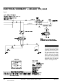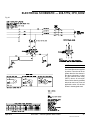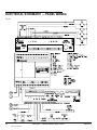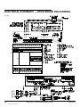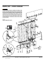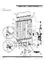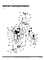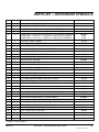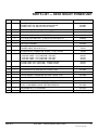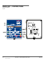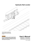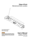
1
Vertical Hydraulic Leveler
40-50K Capacity
This manual applies to Vertical
dock levelers manufactured
beginning February 2013 with the
serial numbers 61070073 and
higher.
Do not install, operate or service this product unless you
have read and understand the Safety Practices, Warnings,
Installation and Operating Instructions contained in this
user’s manual. Failure to do so could result in death or
serious injury.
User’s Manual
Installation, Operations,
Maintenance and Parts
Part No. 6001762N
table of contents
Introduction.......................................................................... 2
Safety Signal Words............................................................ 3
Safety Practices.................................................................. 3
Owner’s Responsibilities..................................................... 4
Deck and Lip Grades........................................................... 5
Installation........................................................................... 6
Components and Specifications........................................ 12
Hydraulic System Operation.............................................. 14
Operating Instructions....................................................... 15
Service Tools .................................................................... 18
Planned Maintenance........................................................ 19
Troubleshooting Guide...................................................... 23
PLC Diagnostics ............................................................... 27
Hydraulic Power Unit Adjustment...................................... 30
Hydraulic Schematic.......................................................... 32
Electrical Schematics........................................................ 33
Main Cylinder Adjustment . ............................................... 39
Parts List........................................................................... 40
Warranty ........................................................................... 57
Distributor Information....................................................... 58
introduction
VSL remote mount assembly
VSL deck mount assembly
Welcome and thank you for choosing a VSL dock leveler.
This user’s manual contains information that you need to safely install, operate and maintain the VSL model dock leveler.
It also contains a complete product description and operating instructions for the VSL remote mounted and VSL deck mounted
designs. Product service guides, parts list and information about ordering replacement parts is available in this manual.
Please read this user’s manual before using your new dock leveler and keep a copy for future reference.
2
6001762N — Vertical Hydraulic Dock Leveler
©2013 4Front Entrematic
April 2013
safety signal words
You may find safety signal words such as DANGER, WARNING, CAUTION or NOTICE throughout this user’s manual. Their
use is explained below:
This is the safety alert symbol. It is used to alert
you to potential personal injury hazards. Obey
all safety messages that follow this symbol to
avoid possible death or injury.
Indicates an imminently hazardous situation which, if not
avoided, will result in death or serious injury.
Indicates a potentially hazardous situation which, if not
avoided may result in minor or moderate injury.
Indicates a potentially hazardous situation which, if not
avoided, could result in death or serious injury.
Notice is used to address practices not related to personal
injury.
safety practices
Read these safety practices before installing, operating
or servicing the dock leveler. Failure to follow the safety
practices could result in death or serious injury.
If you do not understand the instructions, ask your supervisor
to explain them to you or contact your local distributor.
OPERATION:
Restrict use of dock leveler to trained operators. Follow safe
operating procedures described in this user’s manual and in
the operation placard which was shipped with the leveler. The
placard should be posted near the leveler. If either labels or
placard is lost, contact your local distributor for replacement.
Do not use the dock leveler to service trailers outside of its
intended working range which is 6" above dock and 6" below
the building floor.
Do not operate the dock leveler when anyone is in front of it.
Do not operate the dock leveler with equipment, material or
people on the ramp or lip.
Stay clear of the dock leveler when it is moving.
KEEP HANDS CLEAR OF HINGES AT ALL TIMES. Do not use
hands to position dock leveler ramp or lip, or to store dock leveler.
Do not use the dock leveler if it appears damaged or does not
operate properly. Inform your supervisor immediately.
Do not attempt to manually lift the dock leveler ramp or lip. If the
April 2013
dock leveler does not operate correctly using the operational
procedures contained in this user’s manual, do not use the
leveler. Refer to the troubleshooting guide in this user’s
manual. If the dock leveler still does not operate properly call
an authorized service representative.
Do not stand in the driveway between the dock leveler and
the backing truck.
Chock truck wheels or lock truck into place with truck restraining
device and set brakes before loading or unloading.
Never drive on dock leveler unless Green Light is lit on the dock
leveler control panel and the truck bed supports extended lip
or ramp is supported by the concrete below.
Always restore leveler to its safe stored vertical position with lip
extended and Leveler Stop button pressed after servicing truck.
DO NOT walk in front of dock leveler until you:
- Restore the leveler to its safe stored vertical position with
lip extended.
- Press Leveler Stop button to stop the leveler and lip
from moving.
Move all equipment, material or people off the dock leveler and
store the dock leveler after use.
Do not use a fork truck or other material handling equipment
to lower the leveler.
Before chocking wheels or engaging vehicle restraint, dump
air from air ride suspensions and set parking brakes.
6001762N — Vertical Hydraulic Dock Leveler
3
©2013 4Front Entrematic
safety practices, continued
INSTALLATION, MAINTENANCE AND SERVICE:
Place barricades on the dock floor around the dock leveler
and in the driveway in front of the dock leveler while
installing, maintaining or repairing the dock.
If the leveler is left in a disabled condition, the lock-out
pin must be padlocked in position.
Do not operate the dock leveler when anyone is standing
in front of the dock leveler.
Before doing any maintenance or repair under the leveler
be certain that the leveler is stored with the lock-out pin
inserted through the maintenance strut and bracket on the
deck, the Leveler Stop button is pressed, the power
is disconnected and properly tagged or locked out, and
barriers are in place.
All electrical troubleshooting or repair must be done by
qualified technician and must meet applicable codes.
If it is necessary to make troubleshooting checks inside
the control box with power on, USE EXTREME CAUTION!
Do not place fingers or uninsulated tools inside the control
box. Touching wires or other parts inside the control box
could result in electrical shock, serious injury or death.
Vertical levelers ship partially disassembled and require
field assembly. Prior to complete electrical and hydraulic
installation, levelers should be stored safely. If leveler is
mounted on hinges and stored vertically, the lock-out
pin must be inserted through the maintenance strut and
the bracket on deck, and secured with a padlock until the
leveler is completely wired, tested, and fully operational.
Disconnect the power and properly tag or lock out before
entering the pit or doing any maintenance or repair under
the leveler.
owner’s responsibilities
The owner's responsibilities include the following:
The owner should recognize the inherent danger of the
interface between dock and transport vehicle. The owner
should, therefore, train and instruct operators in the safe use
of dock leveling devices.
When a transport vehicle is positioned at the dock, there
shall be at least 4" of overlap between the front edge of the
lip of the dock leveler and the edge of the floor or sill of the
transport vehicle.
Nameplates, cautions, instructions and posted warnings shall
not be obscured from the view of operating or maintenance
personnel for whom such warnings are intended.
Manufacturer's recommended periodic maintenance and
inspection procedures in effect at time of shipment shall be
followed, and written records of the performance of these
procedures should be kept.
A dock leveler that is structurally damaged or has experienced
a sudden loss of support while under load, such as might
occur when a transport vehicle is pulled out from under the
4
dock leveler, shall be removed from service, inspected by
the manufacturer's authorized representative, and repaired
as needed before being placed back in service.
The owner shall see that all nameplates, caution and
instruction markings or labels are in place and legible and
that the appropriate operating and maintenance manuals
are provided to users.
Modifications or alterations of dock leveling devices
shall be made only with written permission of the original
manufacturer.
When industrial trucks are driven on and off transport
vehicles during the loading and unloading operation, the
brakes on the transport vehicle shall be applied and wheel
chocks or positive restraints that provide the equivalent of
wheel chocks engaged.
The dock leveler should never be used outside its vertical
working range or outside the manufacturer's labeled rated
capacity. It must also be compatible with the loading
equipment and other conditions relating to the dock.
6001762N — Vertical Hydraulic Dock Leveler
©2013 4Front Entrematic
April 2013
ramp and lip grades
Fig. 1
Ramp grade
Lip grade
TRUCK BED
POSITION
from DOCK,
(in.)
A
B
O
V
E
D
O
C
K
B
E
L
O
W
DECK and LIP grades, % for Dock leveler length
5’ Leveler
6’ Leveler
8’ Leveler
DECK
LIP
DECK
LIP
DECK
LIP
  6.0
  4.0
  2.0
11.4
8.4
5.4
 5.2
  2.2
-0.8
9.7
  7.2
  4.6
  3.4
  0.9
 -1.7
7.4
5.5
3.5
1.2
-0.8
-2.7
  0.0
  2.4
 -3.8
2.1
-4.2
1.6
-4.7
-2.0
-4.0
-6.0
 -0.6
 -3.6
 -6.6
 -6.8
-9.8
-12.8
 -0.5
 -3.0
 -5.6
-6.7
-9.3
-11.8
-0.4
-2.3
-4.3
-6.6
-8.6
-10.5
D
O
C
K
Deck and lip grade, 16” lip.
April 2013
6001762N — Vertical Hydraulic Dock Leveler
5
©2013 4Front Entrematic
installation
Important Installer Responsibility: Vertical levelers ship
partially disassembled and require field assembly. Prior
to complete electrical and hydraulic installation, levelers
must be stored safely. If leveler is mounted on hinges and
stored vertically, maintenance strut must be secured with
lock-out pin and padlock until the leveler is completely
wired, tested and fully operational. Padlock must not be
removed until leveler is completely wired, tested, and
fully operational. Failure to follow safety practices could
result in death or serious injury.
GENERAL INFORMATION
The successful installation of a vertical leveler requires good
coordination with other trades involved on the site. You must
have a clear access to the dock area, inside and out. Ideally,
the leveler should not be installed until the control panel
is installed, has live power connected to the control panel,
and field wiring to the power unit is complete. This will allow
the complete installation at one time as opposed to making
several trips. The bumper assemblies must not be installed
until the leveler is functional as pit construction errors may
not be evident until that time. Make sure the customer gets
the user’s manual and is properly trained.
Make sure lifting devices are in good condition and have
a rated capacity of at least 3000 lb. at the lifting angle they
are being used. Stand clear of the dock leveler when it
is being placed into the pit. Never allow anyone to stand
on or near the dock leveler when it is being lifted or
placed into the pit. The dock leveler can tip or swing into
bystanders which could result in death or serious injury.
Fig. 2
3/4" UNC load
centering eyebolt
3,000 lb. capacity
minimum
The installed location of the control panel and hydraulic power
unit must be specified on a job specific approval drawing.
PIT CHECK
Check the entire dock leveler pit layout and dimensions to
verify conformance with the job specific approval drawings.
Check electrical service running to the control panel to ensure
it agrees with the phase and voltage of the motor and control
box supplied with the dock leveler. See the wiring diagram
located inside the control panel. Schematics for standard
control panels are provided in this manual.
NOTE:
Conduits which stub out through the rear pit wall must not
project greater than 1". Saw off to 1" if necessary.
Take care when moving the dock leveler to ensure that
the electrical and hydraulic components are not damaged.
6
6001762N — Vertical Hydraulic Dock Leveler
©2013 4Front Entrematic
April 2013
installation, continued
HANDLING AND UNLOADING
The rear fixed hinge channels will be installed first by the
concrete contractor. In most cases, these components will
have arrived at the site much earlier than the levelers. The
levelers will arrive on a truck laid flat with the hydraulic
cylinders facing upward. Spacers will be inserted between
the levelers to prevent damage to the leveler components.
The levelers can be lifted off the truck in stacks of three but
using the forks to separate the levelers is not recommended
as damage to the hydraulic components may occur. The
levelers should be lifted individually by installing a 3/4" UNC
load centering eyebolt through the hole supplied in the lip
plate. See Fig. 2.
Fig. 3
TO INSTALL
NOTE:
Do not install the dock bumpers before the leveler is
operational.
1. Mount and wire the control panel in the location as shown
on the job specific approval drawing. Ensure that the
voltage and phase of the incoming power agrees with
the control panel and the decals on the pump and motor.
Power to the control must come from a user supplied fused
disconnect with correct fuse sizes for the voltage and phase
of the motor. See electrical diagram for correct fuse size.
Torque nut, to
200-250 ft-lbs
4. Insert the maintenance strut bar through the guide bracket
on the leveler and secure the lower end to the frame with
the pin. Insert the pin from the side without standing in
front of or underneath the suspended leveler. See Fig.
3.
5. Allow the leveler to lean away from the dock door until the
lock-out pin can be inserted through the upper end of the
maintenance strut and the bracket on the deck. See Fig. 15,
page 18. Place a padlock through the hole provided in the
lock-out pin. This will prevent any unauthorized activation
of the leveler and is essential to the personal safety of
anyone near this leveler.
April 2013
Pivot
screw
Nylock
Spacers
nut
8 ft. leveler only
2. Pick up the leveler using the load centering eyebolt, and
suspend the leveler vertically as shown in Fig. 2.
3. Align the leveler rear hinges with the fixed hinge section
and insert the two outer hinge pins from the side without
standing in front of or underneath the suspended
leveler. Do not install the center pins until the maintenance
strut has been installed and secured. See Fig. 3 and 15 on
page 18.
Jam nut
Rod
Washer
end
NOTE:
All pins require flat washers under the cotter pin except for
the lockout pin.
Ensure that the leveler is leaning away from the dock
door. If the leveler is standing vertical or leaning towards
the dock door do not proceed with installation.
The lock-out pin must be inserted through the maintenance
strut and the bracket on the deck. The pin must be secured
with a padlock before the lifting device is removed. Failure
to do so could result in death or serious injury.
See Fig. 15 on page 18 for lock-out pin location.
6001762N — Vertical Hydraulic Dock Leveler
7
©2013 4Front Entrematic
installation, continued
6. Install the remaining hinge pins. Secure all five leveler
hinge pins and the lower pin of the maintenance strut with
the flat washers and cotter pins provided.
Fig. 4
7. Remove the lifting device from the leveler lip. Leave the
lip fully extended.
8. The hydraulic power unit is pre-assembled. The deck
mounted assembly will have the power unit attached to the
deck with the hoses pre-assembled. The remote mounted
power unit will be separate on a mounting bracket with
all valves attached. This mounting bracket is designed to
suit many different applications. The mounting position
is specified on the job specific approval drawing for
the project. Fasten the power unit mounting bracket as
required.
9. Lay cardboard or other absorbent material under the
hydraulic power unit. This prevents staining the floor in
the event of an overflow. Place a pan directly under the
reservoir to catch any spilled fluid.
10.The three hydraulic hoses and the leveler stored and
maintained float sensor cables (located on the deck) are
marked with numbers for identification. Do not remove the
plugs from the hydraulic hoses at this time. Feed the hose
assemblies and the sensor cables through the conduit.
11. Remove the plugs and make the connections to the
correct hose fittings. Refer to Fig. 4 for the hydraulic hoses
connections. These fittings are all JIC type and require
no thread sealant.
NOTE:
If the hoses are too long, coil the hoses neatly at the bottom
of the power unit and secure with plastic ties. Do not leave
excess hose under the leveler but leave a loop so hoses are
not pulled tight.
12.Install the solenoid home run cable (deck mount only) and
route it with the stored and float sensors wires through
the conduit to the control panel. Install protective cable
wrap over the wires between the deck and conduit port
in the embed to the control panel in conduit according to
the installation specifications. Allow additional wire in a
manner that leaves a service loop.
Route hoses
through conduit
port in embed
Lip cylinder extend
Main cylinder extend
Cylinder retract, common
13.The electrician can now connect the wiring from the control
panel to the motor and solenoid valves.
8
6001762N — Vertical Hydraulic Dock Leveler
©2013 4Front Entrematic
April 2013
installation, continued
Do not remove the lock-out pin from the maintenance
strut until the following steps have been completed to
ensure that the leveler is functioning property. Failure to
do so could result in death or serious injury.
14.Remove shipping plug from the hydraulic reservoir and
replace with the breather breather cap/dipstick..
15.Turn on power to control panel. Pull out the Leveler
Stop button. The Amber power light should be on. Press
and hold the Raise pushbutton for only 5 seconds while
looking into the hydraulic reservoir fill hole. If the motor
is turning in the correct direction you will immediately see
the fluid level drop. If after 5 seconds you see no drop
in fluid level, stop the pump and switch wires to reverse
the rotation. See troubleshooting guide and electrical
schematics in this manual to correct.
16.Press and hold the Raise pushbutton. The main cylinder
will begin to extend in an abrupt motion. Hold the cylinder
away from the leveler while extending so that it will extend
freely. (The cylinder rod or adjusting end may be damaged
by contact with the deck while extending)
17. If the sound of the pump changes before the cylinder
reaches its full stroke (16"), stop the pump and add 8
ounces of hydraulic fluid (see page 13 under Components
and Specifications for hydraulic fluid specifications).
Continue to run the pump until the main cylinder is fully
extended. Add more fluid if required.
18.Press the Lower button and hold until the main cylinder
is fully retracted. This will eliminate excess air from the
main cylinder. Then press the Lip Retract button and
hold until the lip is fully retracted. Then press the Lip
Extend button and hold until the lip is fully extended.
Then press the Lip Retract button again and hold until
the lip is fully retracted. This will eliminate air from the lip
cylinder. Run both cylinders in/out a minimum of 4 times
until any abrupt motion is eliminated.
19.Oil Inspection — Remote mount assembly: With both the
main cylinder and the lip cylinder retracted, check the
oil level in the reservoir. Oil should be clear and within
1/2"-3/4" of the top with the lip plate fully retracted.
Add oil if necessary. See page 13 under Components and
Specifications for hydraulic fluid specifications. Deck mount
assembly: Inspect the oil level with the deck in the vertical
stored position and the lip extended. remove and clean
the dipstick. reinsert the cap to the top of the opening and
remove to read the oil level on the dipstick. Proper oil level
should be between the holes on the dipstick. See Fig. 17 for
more information. If the oil is foamy, leave for approximately
15 minutes to let the oil settle before checking oil level.
April 2013
6001762N — Vertical Hydraulic Dock Leveler
9
©2013 4Front Entrematic
installation, continued
20.5ft. and 6ft. levelers:
This step requires 1-1/2" and 2" open end wrenches.
Loosen the jam nut on the threaded rod end of the main
cylinder. Press the Raise button and hold until the main
cylinder is fully extended. With the main cylinder rod fully
extended, rotate the rod end so that the pivot pin can be
inserted freely through the cylinder pivot on the embedded
channel frame. Orient the tab on the cylinder pivot pin such
that it goes over the top of the cylinder support bar. See
Fig. 5. Secure the pivot pin with the pin provided. See Fig
3. Ensure the grease fitting faces the dock door.
Fig. 5
8ft. levelers:
This step requires 1-1/2" and 2" open end wrenches.
Loosen the jam nut on the threaded rod end of the main
cylinder. Press the Raise button and hold until the main
cylinder is fully extended. With the main cylinder rod fully
extended, rotate the rod end so that pivot screw and
spacers can be inserted freely through the cylinder pivot
on the embedded channel frame. Add washer and nylock
nut to screw. Torque nut to 200-250 ft-lbs. See Fig 3.
VB420-11F dock bumpers
3/4 dia. x 5" wedge anchor (supplied by others)
Incorrect hydraulic power unit adjustment that allows
the leveler to descend rapidly could result in death or
serious injury.
Stored position 2°-5°
beyond vertical
21.Using the 2" wrench to hold the chrome cylinder rod,
securely tighten the jam nut using the 1-1/2" wrench. Using
the 2" wrench, Turn the chrome cylinder rod clockwise to
pull the leveler forward until the pins in the maintenance
strut move freely.
There must not be more than (1-1/2" on 5' and 6' dock
levelers and 9/16" on 8' dock levelers) of thread showing
on. If more than the allowed amount, do not proceed.
22.Ensure that the pit area is clear. Remove the padlock from
the lock-out pin. Stand at the side of the leveler, reach
in and remove the lock-out pin from the maintenance
strut.
23.Press and hold the Lower button. The pump will run and
the leveler will move forward and start to lower. The alarm
will sound if the leveler is stopped between the lowered
working range and the stored position. Continue to press
the Lower button until the pump stops. The leveler will
hesitate momentarily and the Green light will turn on when
the maintain float sensor trips. When the green light is on,
the leveler is in float. Allow the leveler to fully lower. As
soon as the lip begins to fall, press the Leveler Stop
button. Visually check that the ramp stops are resting on
the front curb steel. If ramp stops are not in full contact
with curb steel, consult factory.
10 Cylinder
support bar
Cylinder
pivot pin
Shim under main
cylinder using 4" x 4"
shims as needed
Bumper mounting
area to be flat
uniform and smooth
6001762N — Vertical Hydraulic Dock Leveler
©2013 4Front Entrematic
Bumper must have good contact
with concrete dock face
April 2013
installation, continued
24.Press and hold the Raise button until the leveler is raised
above the working range and the Green light goes off.
Release the pushbutton. The leveler should remain in
position and the alarm should sound.
25.Press and hold the Raise button until the leveler reaches
the stored position and the lip is fully extended. The Green
light on the control panel should remain off and the alarm
should not sound. Insert the lock-out pin through the
maintenance strut and bracket on the deck. The pin must
insert freely. If there is any resistance, adjust the hydraulic
cylinder as described in steps 1 and 2 on page 39.
26.Remove the lock-out pin and lower the leveler as
instructed in step 22. Observe the lowering speed before
and after the green light turns on. The lowering speeds
should be approximately the same. If not, the lowering
speed after the green light turns on can be adjusted using
the needle valve. Adjust needle valve as necessary, see
page 30 and 31.
27.With the leveler in the fully lowered position, place each
bumper assembly on the floor between the leveler and
the door jamb. A 1" space must be present between the
side of the leveler and the nearest face of the bumper
assembly. This space is important for the bottom pad to
work properly. The bumper assemblies must be welded to
the front curb steel using proper weld techniques. Vertical
down weld passes are not acceptable. All applicable
anchors must be 3/4" x 5" (min. depth) wedge anchors.
See Fig. 5.
NOTE:
Reference TSB 2008-1020G for acceptable anchor bolt
installation practices.
28.Shim and weld as required under main cylinder bracket.
See Fig. 5.
29.Permanently mount the laminated WARNING and
OPERATION instruction placard near the dock leveler
control panel. Make sure the customer gets the user’s
manual and is properly trained to operate the dock leveler.
30.Install the bottom pad. Refer to included installation
instructions.
interlock options
Door Opened
A door opened interlock can be added by adding a door
opened photoeye switch that senses when the door is fully
opened. The leveler lower will not be enabled until the door
is fully opened. The door opened sensor emits an infrared
light beam with a sharp cutoff around 3" beyond the face of
the sensor. The sensor should be positioned below the top
April 2013
Fig. 6
Top view
Door jamb
Door panel
Recommended
photoeye door switch
Door track
Door track
Door switch
mounting
location
Opened (NC)
Detail A
Door
opened
position
Door
closed
position
Finished
opening
Detail B
door opening, (typically 12" below) and on the same side of
the door as the control panel. Position the sensor so it “sees”
the edge of the door panel and the sensor face is around 2"
from the panel. See Fig. 6. Be careful not to let any door parts
such as cables, rollers, etc. to touch the sensor or it will be
damaged. In some applications, it is necessary to fabricate a
simple sheet metal bracket to mount the sensor.
Restraint Interlock
Consult factory.
NOTE:
Position sensor below the top of the door opening for door
opened application and above the top of the door opening for
door closed applications (12"-24" typical). Position the sensor
so that it faces the edge of the door panel with the sensor
face approximately 2" from the door.
6001762N — Vertical Hydraulic Dock Leveler
11
©2013 4Front Entrematic
COMPONENTS and SPECIFICATIONS — Remote mount
The main components of the leveler are shown below. See
the Parts List for specific part numbers.
Fig. 7
Velocity fuse
Lip cylinder
Lip plate
Lip hinge
User warning label
(on both sides)
Deck
assembly
Warning
label
Lock-out pin
with warning
tag
Adjustable rod end
Main lift cylinder
Control Panel (Standard) - NEMA 12, automatic motor
starter, thermal overload, resettable control circuit breaker.
U.L. approved.
Pilot Light - LED.
Solenoid Valves - 24VAC.
Motor - NEMA Standard T.E.N.V. / 48YZ frame,
1hp @ 15 mi. duty cycle, single or three phase.
Pump - Fixed displacement gear pump, 1 gpm, primary relief
valve factory set at 2000 psi.
12 Sequence Pressure - 1750 factory set
Reservoir Capacity - 1.2 U.S. gal., (4.5 lit.) level measured
by visual inspection.
Hydraulic Fluid - Acceptable Hydraulic fluids:
Shell Tellus T 15
Mobil Aero HFA (49011)
Exxon Univis Grade J13
Texaco Aircraft Oil #1554
U.S. Oil Co., Inc #ZFI-5606 (Low Temp.)
6001762N — Vertical Hydraulic Dock Leveler
©2013 4Front Entrematic
Maintenance
strut
April 2013
COMPONENTS and SPECIFICATIONS — deck mount
The main components of the leveler are shown below. See
the Parts List for specific part numbers.
Fig. 8
Lip cylinder
Lip plate
Lip hinge
Velocity fuse
User warning label
(on both sides)
Deck
assembly
Warning
label
Lock-out pin
with warning
tag
Main lift cylinder
Adjustable rod end
Control Panel (Standard) - NEMA 12, automatic motor
starter, thermal overload, resettable control circuit breaker.
U.L. approved.
Pilot Light - LED.
Solenoid Valves - 24VAC.
Motor - NEMA Standard T.E.N.V. / 48YZ frame,
1hp @ 15 mi. duty cycle, single or three phase.
Pump - Fixed displacement gear pump, 1 gpm, primary relief
valve factory set at 2000 psi.
April 2013
Maintenance
strut
Sequence Pressure - 1750 factory set
Reservoir Capacity - 2.84 U.S. gal., (8.9 lit.) level measured
by visual inspection.
Hydraulic Fluid - Acceptable Hydraulic fluids:
Shell Tellus T 15
Mobil Aero HFA (49011)
Exxon Univis Grade J13
Texaco Aircraft Oil #1554
U.S. Oil Co., Inc #ZFI-5606 (Low Temp.)
6001762N — Vertical Hydraulic Dock Leveler
13
©2013 4Front Entrematic
HYDRAULIC SYSTEM OPERATION
The following describes the operation of the hydraulic and
electrical system when the controls are activated.
AUDIBLE ALARM
• Sounds when leveler stops between float and fully stored
position.
• Will silence when Raise, Lower or LEVELER STOP is
pressed.
RAISE pushbutton (continued)
• Green pilot light turns off when leveler raises above working
range.
Fully Raised
• Leveler stored sensor closes.
• Pressure increases
• Sequence valve shifts
LEVELER STOP
Push in
• Control circuit disabled.
• Lip cylinder extends.
• Amber pilot light turns off.
LIP RETRACT pushbutton
• Pump starts.
• Solenoid valves SV2 deenergizes preventing leveler
movement.
• Main solenoid valve SV2 opens allowing leveler to raise
and lip to retract.
Pull out
• Control circuit enabled.
• Green pilot light turns off when leveler raises above the
working range.
• Amber pilot light turns on.
LIP EXTEND pushbutton
• Pump starts.
• Main solenoid valve SV2 remains deenergized except when
RAISE is pressed when pump is running or leveler is lowered
to working range.
• Main cylinder solenoid valve SV2 is closed.
• Sequence valve shifts allowing lip to extend.
LOWER PUSHBUTTON
• Pump starts.
Fig. 9
• Power down solenoid valve SV1 opens to retract main
cylinder. When leveler lowers to working range, the pump
stops, the power down solenoid valve SV1 closes and Main
solenoid valve SV2 is open to allow leveler to float down to
the truck bed.
• Lip solenoid valve SV4 closes to prevent lip from retracting.
• Green pilot light turns on when leveler reaches working
range
Green light
Lip extend
Raise
RAISE pushbutton
• Pump starts.
Lip retract
• Main solenoid valve SV2 opens to extend main cylinder.
Lower
• Lip solenoid valve SV4 closes to prevent lip from retracting.
Leveler
Stop
Power on
Amber light
14 6001762N — Vertical Hydraulic Dock Leveler
©2013 4Front Entrematic
April 2013
operating instructions
Before operating the dock leveler, read and follow the
Safety practices on page 3.
Restrict use of dock leveler to trained operators. Follow
safe operating procedures described in this manual and
in the operation placard which was shipped with the
leveler. The placard should be posted near the leveler.
If either labels or placard is lost, contact your local
distributor replacement.
DO NOT USE DOCK LEVELER IF IT LOOKS DAMAGED,
OR DOES NOT SEEM TO WORK PROPERLY. Inform your
supervisor immediately.
Always be certain that the truck wheels are chocked, or
that the truck is locked in place by a truck restraining
device and the brakes are set before loading or unloading.
Trucks pulling away unexpectedly can cause uncontrolled
drop of the dock leveler which can result in death or
serious injury.
Never drive on dock leveler unless Green Light is lit on
the dock leveler control panel and truck bed supports the
extended lip or the ramp is supported by the concrete
below.
Always return the dock leveler to its safe stored vertical
position with lip extended with the LEVELER Stop button
pressed after servicing truck.
If the truck pulls away before the dock leveler is stored,
the lip will fall to its pendant position and will not be
supported. In addition, failure to properly store the dock
leveler may leave the leveler in a position below dock
level. These conditions may result in unexpected drop
of personnel or material handling equipment and result
in death or serious injury.
If the dock leveler will not raise with the RAISE
pushbutton, and it must be raised by external mechanical
means to close the dock door, use extreme caution and do
not allow anyone to stand in front of the leveler. Ensure
that the lock-out pin is inserted through the maintenance
strut and bracket on deck before the mechanical lifting
means is removed.
April 2013
During lifting of the leveler by mechanical means it is likely
that hydraulic fluid will vent itself through the breather of
the hydraulic reservoir. Lift the leveler slowly and without
getting in front of the leveler, place a container under the
reservoir if possible to catch the fluid.
The lock-out pin must not be removed until the hydraulic
system has been bled of air and all hydraulic functions
have been tested by a qualified service technician.
If the dock leveler has been raised to the stored position
by external means, the main cylinder will be full of air and
there may be a vacuum exerting a strong retracting force
on the cylinder rod. A technician will need to perform a
bleed procedure to remove the air from the hydraulic
cylinder. With the lock-out pin in place, the technician
should loosen the hydraulic hose fitting on the top port
of the main cylinder and allow air to fill the vacuum
before attempting to remove the pin from the cylinder rod
(lower) end. With the lock-out pin in place, the technician
must remove the pin from the main cylinder rod (lower)
end and perform steps 18 through 25 of the installation
instructions on pages 9-11.
Failure to follow this instruction can allow the leveler
to free fall rapidly and may result in severe injury or
death.
INTRODUCTION
The 4Front Entrematic vertical dock leveler is designed
to span and compensate for space and height differences
between a loading dock and freight carrier to allow safe,
efficient freight transfers.
The 4Front Entrematic vertical dock leveler uses pushbutton
controls to position the ramp. Pressing and holding the
Lower button operates a hydraulic pump and retracts a
hydraulic cylinder to lower the ramp. When the ramp is lowered
to the working range, it floats down to rest on the bed of a
trailer forming a bridge. After loading, pressing and holding
the Raise button extends the hydraulic cylinder to raise the
ramp to the stored position. When the dock leveler reaches
its full raised position, a second hydraulic cylinder extends
the dock leveler lip.
Push the LEVELER Stop when the leveler is stored to
prevent operation. With the dock leveler in its fully stored
position, a maintenance strut may be secured with a lock-out
pin to prevent inadvertent operation.
6001762N — Vertical Hydraulic Dock Leveler
15
©2013 4Front Entrematic
operating instructions, continued
Fig. 10
Safety First:
1. Always secure the truck with a vehicle restraint or
wheel chocks and set brakes before operating the
dock leveler.
2. Do not operate dock leveler with anyone standing on
or in front of it.
3. Always keep hands and feet clear of all moving
parts.
4. Always restore the leveler to its safe stored vertical
position with the lip extended and the LEVELER Stop
button pressed after servicing truck.
5. Press LEVELER STOP button to stop leveler and lip
from moving.
Green light on
Press lower button
Pull for power on
Powered/
float down
Amber light on
DO NOT walk in front of dock leveler until you:
• Restore the leveler to its safe stored vertical position
with lip extended.
• Press LEVELER Stop button to stop the leveler from
moving.
Failure to do so could result in death or serious injury.
Normal Operation
1. To lower the dock leveler pull the LEVELER STOP button
on control panel to switch on power. Amber light indicates
power on. Press and hold LOWER button. The pump will
start and the leveler will start to lower. Release the LOWER
button when the Green light on the control panel turns on.
(Green light on leveler control panel indicates leveler has
reached operating range) The leveler will float down to the
truck bed. See Fig. 10.
2. To stop the leveler, release the LOWER button. Audible
Alarm will sound if the button is released before the leveler
is in its operating range. Push the LEVELER STOP button
at any time to stop all operation and silence the Audible
Alarm. If this condition persists, a short duration tone will
sound periodically to remind the operator of the illegal
leveler condition. Amber and Green lights will turn off. To
resume operation of the leveler, pull the LEVELER STOP
button (Amber light on) and press and hold the LOWER
button and leveler will float down to the truck bed. Release
the LOWER button when Green light on leveler control
panel indicates leveler has reached the operating range.
See Fig. 11.
16 Fig. 11
Green light
Press to lower
Push to stop. Pull for power on
Amber light
NOTE:
Audible alarm pulses and green lamp goes off if the
LEVELER STOP button is pressed while leveler is in float
range. Amber lamp flashes if both LS1 and LS2 are on or an
overload condition exists.
6001762N — Vertical Hydraulic Dock Leveler
©2013 4Front Entrematic
April 2013
operating instructions, continued
Storing Leveler
3. To return the leveler to its vertical stored position, press
and hold the RAISE button. Green light will turn off. Audible
Alarm will sound if the button is released before the leveler
is fully raised. When the leveler is fully raised and the lip is
extended, release the RAISE button. Push the LEVELER
STOP button to turn off power (amber light off). See Fig. 12.
Fig. 13
Press to retract lip
Press Lower button
Pull for power on
End Loading Operation
1. Pull the LEVELER STOP button to switch on power. Amber
indicates power on. Press and hold LOWER button until the
leveler is partially lowered. Press and hold LIP RETRACT
button until the lip is fully retracted. Press and hold LOWER
button until Green light on leveler control panel indicates
the leveler has reached the operating range. Leveler will
float down to the pit floor. See Fig. 13.
Amber light on
Float down
2. To reposition the leveler for normal loading/unloading,
press the RAISE button until lip is clear of the truck. The
Green light will go off and the Audible Alarm will sound if
the leveler is stopped above the operating range. Press
the LIP EXTEND button until lip is fully extended. If above
the operating range press and hold the LOWER button
until the Green light on the control panel indicates leveler
has reached the operating range. Leveler will float down
to the truck bed. See Fig. 14.
Fig. 12
Lip in
Green light on
Fig. 14
Green light off
Green light
Press Raise button
Press to raise
Press to extend lip
Press to lower
Push for power off
Lip out
Amber light off
Raise
Push to stop.
Pull for power on
Amber light
Float down
April 2013
6001762N — Vertical Hydraulic Dock Leveler
17
©2013 4Front Entrematic
service tools
Fig. 15
Before servicing the dock leveler, read and follow the
Safety Practices on page 3 and the Operation section in
this manual.
Padlock
Before doing any maintenance or repair on the dock
leveler, be certain that:
1) THE LEVELER IS STORED IN A VERTICAL POSITION
WITH THE LIP EXTENDED AND THE Lock-out pin
INSERTED THROUGH THE MAINTENANCe strut
AND BRACKET ON DECK.
2) The LEVELER Stop button is pressed.
3) Barriers are in place.
Guide bracket
Lock-out pin
Warning tag
Failure to do so could result in death or serious injury.
Maintenance strut
The vertical dock leveler is equipped with a maintenance strut
to hold the leveler in the stored position during maintenance.
Always follow the procedure below when performing
maintenance or adjustments of any kind to the dock leveler.
Maintenance strut
1.Raise the leveler to its fully stored position with the lip
extended.
2. Press the LEVELER Stop button on the control panel.
3) Insert the Lock-out pin through the maintenance strut and
the bracket on the deck. (Reach from the side of the leveler
while inserting Lock-out pin). The Lock-out pin should
insert freely.
4) Place a padlock through the hole in the Lock-out pin to
prevent accidental activation of the dock leveler.
5) Place barricades around the dock leveler to show leveler
is out of service.
18 6001762N — Vertical Hydraulic Dock Leveler
©2013 4Front Entrematic
April 2013
PLANNED MAINTENANCE
To ensure the continued proper operation of your dock leveler,
perform the following planned maintenance procedures.
Before servicing the dock leveler, read and follow the
Safety Practices on page 3 and the Operation section in
this manual.
Before doing any maintenance or repair on the dock
leveler, be certain that:
1) THE LEVELER IS STORED IN A VERTICAL POSITION
WITH THE LIP EXTENDED AND THE LOCK-OUT PIN
INSERTED THROUGH THE MAINTENANCe strut
AND BRACKET ON DECK.
2) The LEVELER Stop button is pressed.
3) Barriers are in place.
Failure to do so could result in death or serious injury.
WEEKLY
quarterly
1. Check that the lock out pin can be freely inserted through
the maintenance strut and the bracket on the deck when
the leveler is fully raised.
1. Inspect and lubricate all mechanical pivot points on the
leveler with S.A.E. 30 oil. Cycle the leveler when lubricating.
2. Check the full operation of the leveler to ensure there is
no hesitation in the hydraulic system. Any loss of fluid will
affect the safety valve operation.
3. Inspect that both control panel lights are working and
replace bulbs if necessary.
4. Clean away any debris from the pit area. If washing out,
take care not to direct spray at any electrical parts.
5. Clean away any dirt and debris from the lip hinge.
2. Inspect the hydraulic cylinders, valves and hoses for
any fluid loss and check the reservoir level. Add fluid as
required. See pages 20 and 21 for oil check procedure for
your model leveler.
NOTE:
To inspect reservoir level, unscrew dip stick cap, clean stick
then insert stick into reservoir. Do not screw in. Read fluid
level and replenish as required. Screw in cap when finished.
3. Inspect all welds under leveler for fatigue or failure,
particularly the lip plate hinge and under the top plate.
4. Inspect all warning labels and placard. Replace as required.
See page 22 for part numbers and label location.
5.Inspect and lubricate the hinge tube and cylinder rod end
clevis (5' and 6' only) with molybdenum disulfide NLGI #2
grease. Do not over-grease. Stop when grease begins to
ooze out of the tube ends. Wipe off excess grease.
6.Inspect dock bumpers. Four inches (4") of projection is
required. Worn, torn, loose or missing bumpers must be
repaired or replaced.
April 2013
6001762N — Vertical Hydraulic Dock Leveler
19
©2013 4Front Entrematic
PLANNED MAINTENANCE, continued
Fig. 16
REMOTE MOUNTED UNITS
Legend
Symbol
Description
Lubricate - Oil
Light Oil - SAE 30
Oil level with
leveler fully lowered
and lip pendant
Lubricate - Grease
Molybdenum Disulfide
NLGI #2
Cleaning
(Location - Frequency)
Visually Inspect
(Replace Damaged Or Worn)
Lip Hinge
(Weekly)
Pins
Hoses
(Quarterly)
Hinge Pins
(5 Places)
Maintenance Strut
(1 Place)
(Except for 8')
20 Pit Area
(Weekly)
6001762N — Vertical Hydraulic Dock Leveler
©2013 4Front Entrematic
April 2013
PLANNED MAINTENANCE, continued
Fig. 17
DECK MOUNTED UNITS
Legend
Symbol
Description
Lubricate - Oil
Light Oil - SAE 30
Maximum oil level
Oil level
with deck in
stored position
and lip extended
Lubricate - Grease
Molybdenum Disulfide
NLGI #2
Minimum oil level
Cleaning
(Location - Frequency)
Visually Inspect
(Replace Damaged Or Worn)
Lip Hinge
(Weekly)
Pins
Hoses
(Quarterly)
Hinge Pins
(5 Places)
Maintenance Strut
(1 Place)
(Except for 8')
April 2013
Pit Area
(Weekly)
6001762N — Vertical Hydraulic Dock Leveler
21
©2013 4Front Entrematic
planned MAINTENANCE, continued
Every 90 days (quarterly) inspect all safety labels and tags
to ensure they are on the dock leveler and are easily legible.
If any are missing or require replacement, please call your
local distributor for replacements.
Fig. 18
6000847
6000873
6007867
6001761
Warning and operation placard
(mounted near controls)
22 6001762N — Vertical Hydraulic Dock Leveler
©2013 4Front Entrematic
April 2013
troubleshooting guide
Use the Troubleshooting Guide if ever the leveler fails
to perform properly. Find the condition that most closely
matches your situation and make the recommended
adjustments. Observe all safety warnings before attempting
any maintenance procedure.
Before servicing the dock leveler, read and follow the
Safety Practices on page 3 and the Operation section in
this manual.
Be certain before doing any maintenance or repair on
the dock leveler, that: 1) THE LEVELER IS STORED
IN A VERTICAL POSITION WITH THE LIP EXTENDED
AND THE LOCK-OUT PIN INSERTED THROUGH THE
MAINTENANCe strut AND BRACKET ON DECK and
2) The power is disconnected and properly tagged or
locked out.
Do not perform any maintenance or repair in the area in
front of, or under the leveler unless the leveler is fully
raised and lip extended, lock-out pin is inserted through
the maintenance strut and bracket on deck, the Leveler
Stop button is pressed, and barriers are in place.
by external means, the main cylinder will be full of air and
there may be a vacuum exerting a strong retracting force
on the cylinder rod. A technician will need to perform a
bleed procedure to remove the air from the hydraulic
cylinder. With the lock-out pin in place, the technician
should loosen the hydraulic hose fitting on the top port
of the main cylinder and allow air to fill the vacuum
before attempting to remove the pin from the cylinder rod
(lower) end. With the lock-out pin in place, the technician
must remove the pin from the main cylinder rod (lower)
end and perform steps 18 through 25 of the installation
instructions on pages 9-11.
Failure to follow this instruction can allow the leveler
to free fall rapidly and may result in severe injury or
death.
Do not disconnect hoses unless the leveler is fully raised
with lip extended, the lockout pin is inserted through the
maintenance strut, Leveler Stop button is pressed, and
barriers are in place. After replacing hoses and/or motor/
pump, cycle the leveler at least four times to remove air
from the cylinder. Check oil and add if required.
Failure to do so could result in death or serious injury.
If the dock leveler will not raise with the RAISE
pushbutton, and it must be raised by external mechanical
means to close the dock door, use extreme caution and do
not allow anyone to stand in front of the leveler. Ensure
that the lock-out pin is inserted through the maintenance
strut and bracket on deck before the mechanical lifting
means is removed.
During lifting of the leveler by mechanical means it is likely
that hydraulic fluid will vent itself through the breather of
the hydraulic reservoir. Lift the leveler slowly and without
getting in front of the leveler, place a container under the
reservoir if possible to catch the fluid.
The lock-out pin must not be removed until the hydraulic
system has been bled of air and all hydraulic functions
have been tested by a qualified service technician.
If the dock leveler has been raised to the stored position
April 2013
6001762N — Vertical Hydraulic Dock Leveler
23
©2013 4Front Entrematic
troubleshooting guide, continued
Do not disconnect hoses or any hydraulic components
unless the leveler is fully raised with lip extended, the lockout
pin is inserted through the maintenance strut, leveler
Stop button is pressed, and barriers are in place.
If you do disconnect any hydraulic components remove
the pin from the main cylinder rod end and perform steps
18 through 25 of the Installation Instructions on pages 911 before removing the lockout pin from the maintenance
strut and bracket on deck.
Failure to do so could result in death or serious injury.
PROBLEM
1.Leveler does not raise or lower.
Motor not running.
POSSIBLE CAUSE
SOLUTION
a) No electrical power to control panel.
a)Check that voltage is present at
terminal connections to the control
panel.
b)Electrical connections incorrect or
broken.
b)Check that wiring matches the wiring
diagram.
c)No electrical power to PLC.
c)No electrical wiring to the PLC.
d)PLC not running.
d)If the fault light is flashing, replace PLC.
a)Loose wiring connection.
a)Check all wiring connections from line
to motor starter relay, overload and to
motor.
b)Voltage drop due to long wiring
distance from power source.
b)Check voltage when motor is started.
Voltage drop is more often a problem
on single phase motors. Verify wire
gage is adequate for length of wire.
a)Overload relay set too low.
a)Set overload to full load current
specified for voltage on motor
nameplate.
b)Loss of 1 phase (Three phase only)
b)Check for voltage at all three motor
connections (T1, T2, T3) at output of
overload in control panel.
4.Leveler does not raise or lower.
Motor hums.
a)Voltage drop.
a)See solution 2. b).
b)Loss of 1 phase (Three phase only)
b)Check for voltage at all three motor
connections (T1, T2, T3) at output of
overload in control panel.
24 6001762N — Vertical Hydraulic Dock Leveler
2.Leveler does not raise or lower;
motor starts then stops, motor
starter relay chatters.
3.Overload relay tripping (check
full load amperage and relay
setting).
©2013 4Front Entrematic
April 2013
troubleshooting guide, continued
PROBLEM
5. Leveler does not raise or lower.
Motor runs.
POSSIBLE CAUSE
SOLUTION
a) Low fluid in reservoir.
a) Check fluid level. See Planned
Maintenance section in this manual
for instructions for your specific leveler
type.
b)Main solenoid valve SV2 does not
open.
b) Check for magnetism at solenoid coil.
If magnetism present, remove and
inspect valve for contamination and
then replace solenoid valve.
c) Pump running in reverse
c) Check motor rotation and reverse
electrical connections T1 and T2 if
necessary.
d) Pump damaged or broken
internally.
d) With the leveler safely secured
by the lock-out pin inserted in the
maintenance strut and bracket on deck,
remove the hose from the upper port of
the main lift cylinder and point free end
into the reservoir opening. If no fluid is
pumped, replace hydraulic power unit.
e) Insufficient pressure. Primary relief
valve (RV1) setting too low.
e) Set primary relief valve to 2000 PSI.
See instructions on page 30 and 31.
a)Lower solenoid valve SV1 does not
open.
a)Check for magnetism at solenoid coil.
If magnetism present, remove and
inspect valve for contamination and
then replace solenoid valve.
b)Automatic safety stop (velocity fuse)
is locked.
b)If load was on the leveler, remove the
load and jog the RAISE or LOWER
buttons to unlock the leveler.
c) NV1 (needle valve) set too tight.
c)Adjust NV1 (needle valve) CCW. See
hydraulic power unit adjustment on
pages 30 and 31.
7. Leveler floats down too fast or
too slowly in “float” range.
a) Float needle (FNV) valve requires
adjustment.
a) Adjust float needle valve. Turn counter
clockwise to increase lowering speed
or clockwise to decrease speed. The
speed of the deck, while lowering, in
the float range should be equal to the
speed in the powered range. See page
30 and 31.
8.Leveler will not raise. Motor
runs.
a) Solenoid valve SV1 not closed.
a)Confirm SV1 solenoid coil is deengergized. Inspect SV1 for
contamination and then replace
solenoid valve.
6. Leveler will not lower. Motor
runs and leveler raises.
April 2013
6001762N — Vertical Hydraulic Dock Leveler
25
©2013 4Front Entrematic
troubleshooting guide, continued
PROBLEM
9. Lip plate will not extend, or
extends too slowly.
POSSIBLE CAUSE
SOLUTION
a) Low fluid level in reservoir.
a) Check fluid level. See Planned
Maintenance section in this manual
for instructions for your specific leveler
type.
b) Sequence valve pressure set too
high.
b) Decrease sequence valve setting. See
page 30 and 31.
c) Lip hinge binding.
c) Inspect hinge area for damage or
trapped debris.
d) Primary relief valve pressure set too
low.
d) Set primary relief valve to 2000 PSI.
See page 30 and 31. Do not adjust
relief valve without a pressure
gauge. Reference TSB 2008-0722G
for equipment requirements.
10. Lip plate extends too soon.
a) Sequence valve pressure set too
low.
a) Turn sequence valve clockwise to
increase pressure so the lip plate does
not extend until the leveler is fully
raised. See page 30 and 31.
11. Lip plate will not stay out/falls
as leveler is lowering.
a) Pilot check valve is leaking.
a)Inspect and clean pilot check valve.
b) Lip solenoid SV4 not energizing or
not closing.
b) Inspect SV4 coil for magnetism.
Test valve with good coil. Replace if
necessary.
c) Lip Solenoid SV4 may be clogged
or damaged.
c)Inspect SV4 valve for contamination,
Clean or replace.
12. Lock-out pin can not be
freely inserted through the
maintenance strut and the
bracket on the deck when the
leveler is fully raised.
a) Main cylinder adjustable rod end
needs adjustment.
a) Adjust as required. See page 39.
13. Audible alarm sounds when
leveler is in the stored position.
a)Main cylinder rod end adjuster not
adjusted correctly.
a)Adjust main cylinder - see page 39.
b)Leveler stored proximity sensor
damaged or connection to sensor
lost.
b)Replace proximity sensor or repair
wiring between sensor and control
panel.
14. Leveler will not enter "Float"
range when lowered (no green
light on control panel, alarm
continues to sound and leveler
stops when in working range).
a)Sensor mounting bracket out of
position.
a)Adjust sensor bracket angle.
b)Leveler float proximity sensor
damaged or connection to sensor
lost.
b)Replace proximity sensor or repair
wiring between sensor and control
panel.
26 6001762N — Vertical Hydraulic Dock Leveler
©2013 4Front Entrematic
April 2013
plc diagnostics
Do not service this product unless you have read and
followed the Safety Practices, Warnings, and Operating
Instructions in this manual. Failure to follow these safety
practices could result in death or serious injury.
The vertical leveler is controlled by a programmable logic
controller (PLC) which reads input signals from pushbuttons
and proximity sensors, and closes the appropriate output
relays to the motor, solenoid valves, audible alarm and
warning lights.
INPUTS
0
Spare
1
Spare
2
Raise PB
3
Lip Extend PB
4
Lip Retract PB
5
Lower PB
6
Stop MB
7
Overload tripped
8
Leveler stored
9
Float
10
Restraint engaged, dip switch #3 (off if used)*
11
Door opened, dip switch #4 (off if used)*
12
Spare
13
Spare
0
1
2
3
4
5
6
OUTPUTS
0
Loading lamp interlock
1
Pilot lamp (Amber)
2
Pilot lamp (Green)
3
VSL fault
4
SV1
5
SV2
6
SV4
7
Motor
8
Audible alarm
9
Door interlock
*See interlocks on page 11.
7
8
9 10 11 12 13
INPUTS
STAT
ERR
RUN
PWR
OUTPUTS
0
1
2
3
4
5
6
7
8
9
The charts below show all of the valid conditions for the
PLC Unit.
0
1
2
3
4
5
6
7
8
9 10 11 12 13
0
1
2
3
4
5
6
7
8
9 10 11 12 13
INPUTS
INPUTS
4
5
6
7
8
9
Leveler stored. No pushbuttons pressed. LEVELER Stop
pulled out.
April 2013
OUTPUTS
ERR
3
STAT
2
RUN
1
PWR
ERR
STAT
RUN
PWR
OUTPUTS
0
0
1
2
3
4
5
6
7
8
9
Leveler stored. Lower button pressed.
6001762N — Vertical Hydraulic Dock Leveler
27
©2013 4Front Entrematic
plc diagnostics, continued
1
6
2
7
3
8
4
9 10 11 12 13
5
6
7
8
0
1
2
3
4
5
6
7
8
2
3
4
5
6
7
8
9 10 11 12 13
INPUTS
INPUTS
OUTPUTS
OUTPUTS
9
Leveler between float and stored. Lower button pressed.
0
1
9 10 11 12 13
ERR
0
5
STAT
4
RUN
3
PWR
ERR
2
STAT
1
RUN
PWR
0
0
1
2
3
4
5
6
7
8
9
Leveler stored. Raise button pressed.
0
1
2
3
4
5
6
7
8
9 10 11 12 13
INPUTS
INPUTS
Leveler in float range. Lower button pressed.
3
4
0
5
1
6
2
7
3
8
4
9 10 11 12 13
5
6
7
8
0
3
4
0
5
1
6
2
7
3
8
4
6
7
8
1
2
3
4
5
6
7
8
4
5
6
7
8
9
1
2
3
4
5
6
7
8
9 10 11 12 13
OUTPUTS
9
0
1
2
3
4
5
6
7
8
9
Leveler stored. Lip Extend button pressed.
0
1
2
3
4
5
6
7
8
9 10 11 12 13
INPUTS
INPUTS
OUTPUTS
OUTPUTS
9
Leveler in float range. Raise button pressed.
0
3
OUTPUTS
9 10 11 12 13
5
2
INPUTS
PWR
ERR
2
STAT
RUN
PWR
1
1
INPUTS
Leveler in float range. No buttons pressed.
0
0
Leveler stored. Lip Retract button pressed.
PWR
ERR
2
STAT
1
RUN
PWR
0
OUTPUTS
ERR
9
STAT
8
ERR
7
STAT
6
ERR
5
STAT
4
RUN
3
RUN
2
RUN
1
PWR
ERR
STAT
RUN
PWR
OUTPUTS
0
0
1
2
3
4
5
6
7
8
9
Leveler between float and stored. No pushbuttons pressed.
9 10 11 12 13
0
1
2
3
4
5
6
7
8
9 10 11 12 13
INPUTS
INPUTS
4
5
6
7
8
9
Leveler between float and stored. Raise button pressed.
28 OUTPUTS
ERR
3
STAT
2
RUN
1
PWR
ERR
STAT
RUN
PWR
OUTPUTS
0
0
1
3
4
5
6
7
8
9
Alarm condition: LS1 and LS2 both on or overload tripped.
No buttons pressed
6001762N — Vertical Hydraulic Dock Leveler
©2013 4Front Entrematic
2
April 2013
plc diagnostics, continued
Fig. 19
VSL Input Board
Input power
supply energized LED
Field terminal
7 position
Field terminal
5 position
Input power
supply fuse 1/4 amp
Output
Fuse and light
Interlock supply fuse Alarm Heater
diagnostics LED’s fuse 2A
8A
socket socket
VSL Output Board
Diagnostic LED’s
SV1
SV2
SV4
Lights
F4
On when power is being sent to output solenoid 1.
On when power is being sent to solenoid 2.
On when power is being sent to solenoid 4.
Off when power supplying the lights is not present.
Off when power supplying all the solenoids and control circuit is off
or F4 fuse is blown.
Input Power LED off when PLC input power supply fuse 0.25A is blown.
NOTE:
There is no LED indicator for the 2A interlock fuse.
April 2013
6001762N — Vertical Hydraulic Dock Leveler
29
©2013 4Front Entrematic
HYDRAULIC POWER UNIT ADJUSTMENT
Fig. 20
REMOTE MOUNTED UNITS
SV4: lip solenoid valve
SQ: sequence valve
adjust lip activation timing
FNV
float needle
valve
RV1: primary relief valve
adjust maximum system pressure
C2: Lip cylinder
extend hose
C1: Main cylinder
extend hose
C3: Cylinder retract
common hose
SV2: main
solenoid valve
A
SV1: power down
solenoid valve
NV1: Power down needle
valve adjust lowering speed
Fig. 21
DECK MOUNTED UNITS
SV1: power down
solenoid valve
SV2: main
solenoid valve A
SQ: sequence valve
adjust lip
activation timing
SV4: lip solenoid valve
FNV:
float needle
valve
30 NV1: Power down
needle valve adjust
lowering speed
6001762N — Vertical Hydraulic Dock Leveler
©2013 4Front Entrematic
RV1: primary relief valve
adjust maximum
system pressure
April 2013
HYDRAULIC POWER UNIT ADJUSTMENT, continued
Fig. 22
Do not perform any maintenance or repair in the area in
front of, or under the leveler unless the leveler is fully
raised and lip extended, lock-out pin is inserted through
the maintenance strut and bracket on deck, the Leveler
Stop button is pressed, and barriers are in place.
Before making any adjustments to the power unit, always
install a hydraulic pressure gauge (3000 psi liquid filled),
in line, on the C1 port.
Tools Required
● Pressure gauge (3000 psi, liquid filled)
● 3/16" hex wrench
● 7/16" open end wrench
● 9/16" open end wrench.
Test gauge
(3,000 psi)
C1 port
DescriptionPurposeAdjustment
Primary relief
valve (RV1)
Controls maximum
pressure in the hydraulic
system and protects the
other components from
excessive force.
Loosen the lock nut. Turn screw clockwise to increase relief pressure.
Relief pressure is factory set at 2,000 PSI and should not require
adjustment. Do not adjust without a pressure gauge or pump may be
damaged. Reference TSB2009-0722G equipment requirements.
Float needle
valve (FNV)
Controls the lowering
speed of the leveler in the
float range when the green
light is on.
Loosen jamb nut with 7/16" wrench. Turn the knob clockwise to decrease
lowering speed. The speed of the deck, while lowering, in the float range
should be equal to or slower than the speed in the powered range.
Sequence valve
Controls lip plate retraction
and extension.
Loosen locknut. turn set screw CW (inward) to increase pressure, CCW
(outward) to reduce pressure. If the lip extends before the deck is fully
raised, the valve should be turned clockwise. Tightening the valve too
far will cause very slow lip extension, or no extension at all.
Power down
needle valve
(NV1)
Controls the lowering
speed of the leveler while
under power.
Trial run the leveler, lowering it from stored to below dock position.
Record time observed.
April 2013
NV1 Adjustment: With the leveler at
rest in below dock position, loosen the
NV1 needle valve lock nut and turn the
knob clockwise to slow lowering speed,
or counter-clockwise to increase speed.
Hold the adjustment knob in place
while tightening the lock nut. Raise the
leveler and test lowering speed. Make
adjustments in 1/4 to 1/2 turn increments
with each test.
6001762N — Vertical Hydraulic Dock Leveler
31
©2013 4Front Entrematic
hydraulic schematic
Fig. 23
SV4
FNV
NV1
32 6001762N — Vertical Hydraulic Dock Leveler
©2013 4Front Entrematic
April 2013
ELECTRICAL SCHEMATIC — 120V, 1ph, 60hz
Fig. 24
Before doing any electrical work, make certain the power
is disconnected and properly tagged or locked off. All
electrical work must be done by a qualified technician
and meet all applicable codes. If it is necessary to make
troubleshooting checks inside the control box with
the power on, USE EXTREME CAUTION. Do not place
your fingers or uninsulated tools inside the control box.
Touching wires or other parts inside the control box
could result in electrical shock, death or serious injury.
NOTE:
Power to control box must be
from fused disconnect supplied
by others. Fuse size can be no
greater than the size shown in
the above schematic or chart
for dual element time delay
(DETD) fuses. All electrical
work must be done by qualified
technician and must meet all
applicable codes. All devices
shown in deenergized state.
April 2013
6001762N — Vertical Hydraulic Dock Leveler
33
©2013 4Front Entrematic
ELECTRICAL SCHEMATIC — 208-240V, 1ph, 60hz
Fig. 25
NOTE:
Power to control box must be
from fused disconnect supplied
by others. Fuse size can be no
greater than the size shown in
the above schematic or chart
for dual element time delay
(DETD) fuses. All electrical
work must be done by qualified
technician and must meet all
applicable codes. All devices
shown in deenergized state.
34 6001762N — Vertical Hydraulic Dock Leveler
©2013 4Front Entrematic
April 2013
ELECTRICAL SCHEMATIC — 208-575V, 3PH, 60hz
Fig. 26
NOTE:
Power to control box must be
from fused disconnect supplied
by others. Fuse size can be no
greater than the size shown in
the above schematic or chart
for dual element time delay
(DETD) fuses. All electrical
work must be done by qualified
technician and must meet all
applicable codes. All devices
shown in deenergized state.
April 2013
6001762N — Vertical Hydraulic Dock Leveler
35
©2013 4Front Entrematic
ELECTRICAL SCHEMATIC — panel wiring
Fig. 27
36 6001762N — Vertical Hydraulic Dock Leveler
©2013 4Front Entrematic
April 2013
ELECTRICAL SCHEMATIC — remote mount Field wiring
Fig. 28
LS2
LS1
April 2013
6001762N — Vertical Hydraulic Dock Leveler
37
©2013 4Front Entrematic
ELECTRICAL SCHEMATIC — deck mount Field wiring
Fig. 29
38 6001762N — Vertical Hydraulic Dock Leveler
©2013 4Front Entrematic
April 2013
MAIN CYLINDER — ADJUSTMENT
Fig. 30
Before servicing the dock leveler, read and follow the
Safety Practices on page 3 and the Operation section in
this manual.
Be certain before doing any maintenance or repair on
the dock leveler, that: 1) THE LEVELER IS STORED
IN A VERTICAL POSITION WITH THE LIP EXTENDED
AND THE LOCK-OUT PIN INSERTED THROUGH THE
MAINTENANCe strut AND BRACKET ON DECK and
2) The power is disconnected and properly tagged or
locked out.
Vertical leveler in stored position
Vertical line
Stored position 2°-5°
beyond vertical
Failure to do so could result in death or serious injury.
1. This requires a 1-1/2" and 2" open end wrenches. Loosen
the jam nut on the threaded rod end of the main cylinder.
Leveler stored
sensor LS1
Maintain float
sensor LS2
2. Using the 2" wrench to hold the chrome cylinder rod, tighten
the jam nut using the 1-1/2" wrench. Turn the chrome
cylinder rod counter-clockwise to push the leveler back or
clockwise to pull the leveler forward until the lockout pin in
the maintenance strut move freely. See Fig. 31.
NOTE:
See Page 18 for maintenance strut operation.
Fig. 31
There must not be more than 1-1/2" of thread showing
on the adjustable rod end on 5' and 6' models and 9/16"
on 8' models. If more than specified thread shows, do
not proceed.
Ensure that the leveler is leaning away from the dock
door. If the leveler is standing vertical or leaning towards
the dock door than the leveler is not in a safe stored
position. Correct immediately using the steps above.
Failure to do so could result in death or serious injury.
April 2013
Rotate cylinder rod
clockwise to tilt
leveler forward
Rotate cylinder rod
counter-clockwise
to tilt leveler back
Lock nut
Adjustable
rod end
1-1/2" on 5' and 6'
9/16" on 8' models
6001762N — Vertical Hydraulic Dock Leveler
39
©2013 4Front Entrematic
PARTS LIST — DOCK LEVELER
To ensure proper function, durability and safety of the
product, only replacement parts that do not interfere with
the safe, normal operation of the product must be used.
Incorporation of replacement parts or modifications that
weaken the structural integrity of the product, or in a way
alter the product from its normal working condition at the
time of purchase from 4Front Entrematic could result in
product malfunction, breakdown, premature wear, death
or serious injury.
33
5
2
Fig. 32
REMOTE MOUNTED UNITS
1
5 & 6FT 4
7
7
11
6
8FT
or 14
5
5
11
6
11
19
9
18
12
10
3
15
8
13
26
16
11
5
5 Foot and 6 Foot Leveler
17
11
Note:
Torque nut,
Item 24 to
200-250
ft-lbs
17
23
22
5
11
20
5
24
25
11
4
5
11 26
8 Foot Leveler
40 6001762N — Vertical Hydraulic Dock Leveler
©2013 4Front Entrematic
April 2013
PARTS LIST — DOCK LEVELER, continued
Fig. 33
DECK MOUNTED UNITS
1
33
7
9
18
13
15
10
26
11
3
5
5 Foot and 6 Foot Leveler
16
5
17
11
11
23
22
5
4
24
17
11
25
27
8 Foot Leveler
30
29
32
April 2013
31
28
6001762N — Vertical Hydraulic Dock Leveler
41
©2013 4Front Entrematic
PARTS LIST — DOCK LEVELER, continued
Capacity and Part Number
Item
Quantity Description
40K
45K
50K
1
1
Hinge Pin 6'
586-0287
586-0287
586-0287
1
Hinge Pin 6-1/2'
586-1495
586-1495
586-1495
1
Hinge Pin 7'
586-0392
586-0392
586-0392
Item
Quantity DescriptionPart Number
2
*
Drive Fit Grease Fitting
417-113
3
1
Lock-Out Pin Assy.
6000307
4
6
Pin, Rear Hinge, Hyd Cyl.
5861066
5
10
Pin, cotter 5/32 zinc plated
6001832
6
3
PIN, 1X2-1/8, DRILLED
586-1063
7
2
SLK Pins 21S-250-2250 or equal (40-50K)
231-126
8
2
Float/Stored Sensor Assy
6000749
9
2
User Hazard Label
6000847
10
1
Lock-Out Tag
6000873
11
10
Plated washer, 1-1/16" hole
234-093
12
1
Danger - Warning label
6007867
13
1
Serial tag
6009761
14
1
Pin Clevis Upper 8' VSL
6009400
15
1
Padlock
341-034
16
1
Maintenance strut
6002009
17
1
Hex Head Jamnut 1-8UNC
6009441
18
2
Brand label — Serco
Brand label — Kelley
6001712
6001713
19
1
Wall Mounted Placard – Safety and Operations
6001761
20
1
Rod End Adj. Assy. (5' and 6' units only)
6001315
21
1user’s manual
6001762
22
1
Hex Head Screw 1-8UNC GR8 (8' unit only)
6008648
23
1
Rod End Assy 1-8" (8' unit only)
6008650
24
1
Nylock Nut 1-8UNC (8' unit only)
6009440
25
2
Spacer Bushing VSL Rod End (8' unit only)
6008649
26
1
VSL PIN ANTI-ROTATE WDMT
6013879
27
2
5/16" Nylon locknut (Deck mount units only)
214522
28
2
5/16" steel washer (Deck mount units only)
000055
29
2
Carriage bolt 5/16" x 1" (Deck mount units only)
6010662
30
2
Stainless hose clamp, 7" (Deck mount units only)
6014352
31
1mount Damper (Deck mount units only)
6014356
32
1
6014353
VSL DM bracket WDMT (Deck mount units only)
42 6001762N — Vertical Hydraulic Dock Leveler
©2013 4Front Entrematic
April 2013
PARTS LIST — DOCK LEVELER, continued
Capacity and Part Number
Item
Quantity Description
40K
45K
50K
33
1
Lip Assy. 6 ft x 16 in
3-3362
3-3371
3-3380
1
Lip Assy. 6 ft x 18 in
3-3363
3-3372
3-3381
1
Lip Assy. 6 ft x 20 in
3-3364
3-3373
3-3382
1
Lip Assy. 6.5 ft x 16 in
3-3365
3-3374
3-3383
1
Lip Assy. 6.5 ft x 18 in
3-3366
3-3375
3-3384
1
Lip Assy. 6.5 ft x 20 in
3-3367
3-3376
3-3385
1
Lip Assy. 6.5 ft x 16 in - 3" Taper
3-3783
3-3786
3-3789
1
Lip Assy. 6.5 ft x 18 in - 3" Taper
3-3784
3-3787
3-3790
1
Lip Assy. 6.5 ft x 20 in - 3" Taper
3-3785
3-3788
3-3791
1
Lip Assy. 7 ft x 16 in - 3" Taper
3-3801
3-3804
3-3807
1
Lip Assy. 7 ft x 18 in - 3" Taper
3-3802
3-3805
3-3808
1
Lip Assy. 7 ft x 20 in - 3" Taper
3-3803
3-3806
3-3809
1
Lip Assy. 7 ft x 16 in - 6" Taper
3-3368
3-3377
3-3386
1
Lip Assy. 7 ft x 18 in - 6" Taper
3-3369
3-3378
3-3387
1
Lip Assy. 7 ft x 20 in - 6" Taper
3-3370
3-3379
3-3388
1
Lip Assy. 7 ft x 16 in - Notch
3-3819
3-3822
3-3825
1
Lip Assy. 7 ft x 18 in - Notch
3-3820
3-3823
3-3826
1
Lip Assy. 7 ft x 20 in - Notch
3-3821
3-3824
3-3827
April 2013
6001762N — Vertical Hydraulic Dock Leveler
43
©2013 4Front Entrematic
PARTS LIST — remote mount hydraulic
Fig. 34
5
D
6
Detail A
12
9
A
4
2
Detail B
7
8
3
B
3
C
1 15
2
Detail C
11
14
1 14 15
9
4
10
Lip cylinder extend
Main cylinder extend
Section D
44 Cylinder retract common
6001762N — Vertical Hydraulic Dock Leveler
©2013 4Front Entrematic
April 2013
PARTS LIST — remote mount hydraulic, continued
Item
Quantity DescriptionPart Number
1
2
Lock Nut 1/4-20 UNC NYLOCK
214-502
2
2
Hose Assy: 1/2 x 24 ft.
3-1650
3
1
Hose Assy: 1/2 x 31.5"
3-1960
4
1
Hose Assy: 1/2 x 37" (5ft Leveler)
Hose Assy: 1/2 x 48" (6ft Leveler)
Hose Assy: 1/2 x 72" (8ft Leveler)
6000722
3-1959
6000724
5
1
Street Elbow 1/2" NPT x #8J1C
313-102
6
1
Velocity Fuse - 10 GPM
313239
7
1
Hose Assy: 1/2" ID x 24', 100R2
6006657
8
1
Tee, Male #6 JIC
6000595
9
2
Male 90º Elbow, 1/4 - NPT x #6 JIC
313-106
10
1
Male 45º Elbow, 1/4 - NPT x #6 JIC
313-219
11
1
Main Cylinder, 3.5x16 Stroke Double Acting
6000620
12
1
Lip Cylinder, 2.5x6 Stroke Double Acting
313-043
13
3
Plug: #6 JIC — not shown
313-236
14
2
Dual Hose Clamp - 1/2" Hose
6000837
15
2
HHMS 1/4-20UNC x 1 Zinc
212-005
April 2013
6001762N — Vertical Hydraulic Dock Leveler
45
©2013 4Front Entrematic
PARTS LIST — deck mount hydraulic
Fig. 35
31
33
32
19
2
20
31
29
33
32
31
32
30
27
28
14
21
8
7
18
6
34
1
17
22
16
14
19
15
16
5
4
3
26 24
12
23
12
32
35
46 25
28
26
26
13
6001762N — Vertical Hydraulic Dock Leveler
©2013 4Front Entrematic
April 2013
PARTS LIST — deck mount hydraulic
Item
Quantity DescriptionPart Number
1
1
MAIN CYL, 3.5 X 16" STK, DBL ACTION
6000620
2
1
LIP CYL, 2.5 X 6"ST, DBL ACTION
313043
3
1
HOSE ASSY : 1/2 ID X 36" LOA -8 STR-FS x 8STR-FS
6013450
4
1
HOSE ASSY: 1/4 ID X 19" LOA -6 EL90 JIC FS x 6 STR-FS
6003818
5
2
HOSE ASSY: 1/4 ID X 45" LOA -6 STR-FS x 6 STR-FS (5ft Leveler)
HOSE ASSY: 1/4 ID X 57.5" -6 STR-FS x 6 STR-FS (6ft Leveler)
HOSE ASSY: 1/4 ID X 75.5" -6 STR-FS x 6 STR-FS (8ft Leveler)
6001021
31245
31247
6
1
VELOCITY FUSE - 10GPM
313239
7
1
HOME RUN CABLE QD, 5 LEADS
6010347
8
1
CORD SET, QD, SLP, SV1-SV4
6010346
9
2
#8-32 X 7/8" LG, PAN HEAD MACHINE SCREW 6011671
10
2
LN, #10-24 UNC, ZP
6001878
11
1
HANGER BRACKET, WIRE HARNESS
6013451
12
2
CONN CGB195
533424
13
1
4X4XS J-BOX, VSLW DM
6002002
14
2
NYLON LOCK NUT, 1/4-20UNC, ZINC
214502
15
2
HHMS 1/4-20UNC X 1 ZINC
212005
16
2
CLAMP, TUBE, INSULATED, 7/8"ID
6006655
17
1
CLAMP, TUBE, INSULATED, 1/2"ID
6006656
18
1
CLAMP, DOUBLE TUBE, 9/16" DIA.
6000837
19
2
FTG, ELBOW NIPPLE -1/4"NPTM x 6 JIC-M
313106
20
1
FTG, MALE 45 DEG ELBOW:1/4" NPTM x 6 JIC-M
313219
21
1
FTG, STREET ELBOW - 1/2 NPTM X 1/2 NPTF
313102
22
1
FTG, RUN SW TEE, 6 JIC-M X 6 JIC-F SW X 6 JIC-M
313105
23
2 FT. SPIRAL WRAP - 3/8 ID 532320
24
1
HEX NUT 1"-8 UNC FINISHED (5ft and 6ft Leveler only)
214341
25
1
CYLINDER END VSLW (5ft and 6ft Leveler only)
6002566
26
1
LOWER ROD END KIT VSL MAIN CYL (8ft Leveler only)
6008750
27
1
PIN CLEVIS UPPER MAIN (8ft Leveler only)
6009400
28
1
PIN 1" X 3 1/2 LG, TAPER, DRILLED (5ft and 6ft Leveler only)
5861066
29
4
5/16-18 X 3/4" LG ROUND HEAD CARRIAGE BOLT
6010662
30
4
5/16-18 HEX NUT FLANGED- SERRATED
6010661
31
4*
PIN,COTTER 5/32X2 ZINC PLT
6001832
32
4*
PW, 1" BOLT SIZE 1-1/16 HOLE
234093
33
2
PIN 1IN DIA X 2-3/16 LG
5861063
34
2
FLOAT/STD SENSOR ASSY, V2
6000749
35
1
VSL PIN ANTI-ROTATE WDMT (5' AND 6' UNITS ONLY)
6013879
*Quantity: 3 on 8FT levelers.
April 2013
6001762N — Vertical Hydraulic Dock Leveler
47
©2013 4Front Entrematic
PARTS LIST — REMOTE MOUNT POWER UNIT
Fig. 36
1
22
21
13
14
18
15
11
19
23
20
9
16
8
12
6
2
15
24
5
9
7
16
17
3
2
4
10
48 6001762N — Vertical Hydraulic Dock Leveler
©2013 4Front Entrematic
April 2013
PARTS LIST — REMOTE MOUNT POWER UNIT, continued
Item
Quantity DescriptionPart Number
1
1
HYDRAULIC POWER ASSY, VSL, 120-220V/1/50-60
HYDRAULIC POWER ASSY, VSL, 208-480V/3/50-60
HYDRAULIC POWER ASSY, VSL, 575V/3/60
2
2
Hose Assy : 1/4 ID x 24 FT .LG , 6 JIC SWIVEL END FTG
31650
3
1
Hose Assy : 1/2 IN X 24 FT LG , 8 JIC SWIVEL END FTG
6006657
4
1
BRACKET WDMT, PUMP WALL MOUNT - BHGR
6012018
5
1
FTG, STR THD CONN, 8-JIC-M x 6-SAE ORB-M, STL
6006640
6
1
FTG.,ELBOW- 90 SWIVEL NUT, 8-JIC-M x 8-JIC-F STL
6011446
7
1
FTG, STR THD CONN, 6-JIC-M x 6-SAE ORB-M , STL
6000717
8
1
FTG, LNG STR THD CONN ,6-JIC-M x 6-SAE-ORB, STL
6012007
9
2
FTG.,ELBOW- 90 SWIVEL NUT,6-JIC-M x 6-JIC-F STL
313595
10
4
SERRATED FLANGE HEX LOCKNUT, 5/16-18UNC, ZP
6010661
11
4
5/16-18UNC X 1" LG ROUND HEAD CARRIAGE BOLT, ZP
6010662
12
3
MOLDED SOLENOID CORD SET, DIN 43650, 2M
6008052
13
1
120 VOLT LABEL - EXT. (on pump)
208 VOLT LABEL - EXT. (on pump) 240 VOLT LABEL - EXT.(on pump) 480 VOLT LABEL - EXT. (on pump) 575 VOLT LABEL - EXT. (on pump)
921-051
921-050
921-052
921-053
921-054
14
1
SINGLE PHASE LABEL- EXT. (on pump)
THREE PHASE LABEL- EXT. (on pump)
921-026
921-027
15
3
COIL, SOLENOID 24VAC
6011937
16
2
VALVE, NC SPOOL sol. valve, sv1, sv2
6011935
17
3
SOLENOID NUT, 1/2, SM
6011725
18
1
VALVE, NO 2 WAY POPPET SOL. VALVE, SV4
6011480
19
1
VALVE, PRESS. SEQ., DIRECT ACT CARTRIDGE 6011698
20
1
VALVE, NEEDLE, CARTRIDGE, ADJ, SAE THRD FNV
6011699
21
1
RESERVOIR KIT, 0.94 GAL STEEL TANK
6012633
22
1
BREATHER CAP, DIPSTick
6012637
23
1
SOLENOID NUT , 1/2", LG
6011726
24
1
NEEDLE VALVE ASSEMBLY NV1 6012012
April 2013
6012602
6012603
6012604
6001762N — Vertical Hydraulic Dock Leveler
49
©2013 4Front Entrematic
PARTS LIST — deck MOUNT POWER UNIT
Fig. 37
7
1
9
14
12
3
8
18
4
19
16
2
15
10
11
19
6
12
18
13
18
20
5
6
17
50 6001762N — Vertical Hydraulic Dock Leveler
©2013 4Front Entrematic
April 2013
PARTS LIST — deck MOUNT POWER UNIT
Item
Quantity DescriptionPart Number
1
1
POWER UNIT, VSL -DM,120-220V/1/50-60 -BHGR
POWER UNIT, VSL -DM, 240-480V/3/50-60 -BHGR
POWER UNIT, VSL -DM,575V/3/50-60 -BHGR
6012949
6012950
6012951
2
1
FTG, 45° PIPE ELBOW 3/4-CD45
6013449
3
1
FTG, PIPE NIPPLE, 3/4" NPT X 4" LG, STEEL
6012997
4
1
FTG, PIPE COUPLING, 3/4" NPT, STEEL
6012998
5
1
FTG, STR THD CONN, 8-37° FLARE-M x 6-SAE OR-M, STL
6006640
6
2
FTG, STR THD CONN, 6-37° FLARE MALE x 6-SAE OR-M , STL
6000717
7
1
DIPSTICK ASSEMBLY
6012934
8
1
POWER CABLE, SO 14/4 X 60" LG
POWER CABLE, SO 14/3X 60" LG
172603
172607
Strain Relief Connector, 90 Deg , 1/2 In, -5/8 CBL
145084
10
1
VOLTAGE LABEL - EXT. (on pump ) 120 Volt
VOLTAGE LABEL - EXT. (on pump ) 240 Volt
VOLTAGE LABEL - EXT. (on pump ) 480 Volt
VOLTAGE LABEL - EXT. (on pump ) 575 Volt
921051
921052
921053
921054
11
1
PHASE LABEL- EXT. (on pump ) "SINGLE PHASE"
PHASE LABEL- EXT. (on pump ) "THREE PHASE"
921026
921027
12
2
SOLENOID VALVE, 2W2P, #8, NC, SPOOL (SV1 & SV2)
6011935
13
1
SOLENOID VALVE, 2W2P, #8, NO, POPPET (SV4)
6011480
14
1
VALVE, PRESS. SEQ. DIRECT ACT CARTRIDGE 6011698
15
1
VALVE, NEEDLE, CARTRIDGE, ADJ, SAE 4 THRD (FNV)
6011699
16
1
VALVE, NEEDLE, CARTRIDGE, ADJ, SAE 4 THRD (NV1)
6012012
17
1
RES KIT, 0.94 GAL, STEEL (TANK, FILTER O-RING, RET. SCREWS)
6012633
18
3
COIL, 1/2 SOLENOID 24VAC, Deltrol Series 8 COIL, 1/2 SOLENOID 125VAC, Deltrol Series 8
6011937
6011938
19
2
RETAINING NUT, 1/2" SOLENOID
6011725
20
1
RETAINING NUT, 1/2" SOLENOID,LONG
6011726
9
April 2013
1
6001762N — Vertical Hydraulic Dock Leveler
51
©2013 4Front Entrematic
PARTS LIST — control panel
480V shown (typical)
Fig. 38
22
9
1
4
5
2
11 16 17
7
12 16 17
13 16 17
14 16 17
6
3
8
10
15
16 18
52 6001762N — Vertical Hydraulic Dock Leveler
©2013 4Front Entrematic
21
April 2013
PARTS LIST — control panel, continued
Where Used/Quantity
Complete Control Panel Kelley
Assy. Number
Serco
ItemPart DescriptionPart Number
6003328V1
6003328V2-V3
6003328V4-V5
6003328V7
6003328V8
6003327V1
6003327V2-V3
6003327V4-V5
6003327V7
6003327V8
120V/1/60
208-240V/1/60
208-240V/3/60
480V/3/60
575V/3/60
1XFMR, 200VA, 120-240V / 24V
6014593
1
XFMR, 208/600V - 120/24V
6012568
1
1
1
1
2
Contactor, 18AMP, 24V COIL 50/60 HZ
Contactor, 9AMP, 24V COIL 50/60 HZ
6000467
1
6012924
1
1
1
1
3
Overload 12 - 18 amps
Overload 9-13 amps
Overload 5.5 - 8 amps
Overload 4 - 6 amps
Overload 1.6 - 2.5 amps
6013781
1
6012560
1 (V2)
6012559
1 (V3)
6013883
1
6012557
1
1
4
FUSE BLOCK, 1 POLE, FINGERSAFE
FUSE BLOCK,2 POLE,FINGERSAFE
6006849
1
6006850
1
1
1
1
5
FUSE, 4A-FNQR, CLASS CC, 600V
FUSE, 3A-FNQR, CLASS CC, 600V
FUSE, TIME DELAY 2A, FNQ-R-2
FUSE, 1A, 600V, CLASS CC - FNQ-R-1
6014368
1
6009361
2 (V2)
2 (V4)
6009546
2 (V3)
2 (V5)
6011963
2
2
6
TWIDO PLC
6001056
1
1
1
1
1
7
VSL INPUT BOARD ASSEMBLY
6003321
1
1
1
1
1
8
VSL OUTPUT BOARD ASSEMBLY
6003322
1
1
1
1
1
9
PILOT LIGHT LED GREEN 24VAC/DC
6014257
1
1
1
1
1
10
PILOT LIGHT LED AMBER 24VAC/DC
6014259
1
1
1
1
1
11
PUSH BUTTON, BLUE
6013066
1
1
1
1
1
12
PUSH BUTTON, GREEN
6013065
1
1
1
1
1
13
PUSH BUTTON, BLACK
6012561
1
1
1
1
1
14
PUSH BUTTON, YELLOW
6013067
1
1
1
1
1
15
MUSHROOM PUSH/PULL BUTTON
6012566
1
1
1
1
1
16
BODY, MOUNTING COLLAR
6012562
5
5
5
5
5
17
BLOCK, CONTACT, NORMALLY OPEN
6012563
4
4
4
4
4
18
BLOCK, CONTACT, NORMALLY CLOSED
6012564
2
2
2
2
2
19
TERMINAL, 2 CONDUCTOR
6000542
3
3
3
3
3
20
TERMINAL, ENDPLATE
6000539
1
1
1
1
1
21
Audible Alarm 6003335
1
1
1
1
1
22
Panel Face Label (SERCO)
Panel Face Label (KELLEY)
6006289
6006288
1
1
1
1
1
1
1
1
1
1
April 2013
6001762N — Vertical Hydraulic Dock Leveler
53
©2013 4Front Entrematic
NOTES
54 6001762N — Vertical Hydraulic Dock Leveler
©2013 4Front Entrematic
April 2013
NOTES
April 2013
6001762N — Vertical Hydraulic Dock Leveler
55
©2013 4Front Entrematic
NOTES
56 6001762N — Vertical Hydraulic Dock Leveler
©2013 4Front Entrematic
April 2013
limited warranty
THIS LIMITED WARRANTY IS 4FRONT’S SOLE AND EXCLUSIVE WARRANTY WITH RESPECT TO THE
DOCK LEVELER AND IS IN LIEU OF ANY OTHER GUARANTEES OR WARRANTIES, EXPRESS OR IMPLIED
4FRONT warrants that this DOCK LEVELER will be free from flaws in material and workmanship under normal
use for a period of one (1) year from the earlier of 1) 60 days after the date of initial shipment by 4FRONT, or 2)
the date of installation of the DOCK LEVELER by the original purchaser, provided that the owner maintains and
operates the DOCK LEVELER in accordance with this user’s manual.
Hydraulic Limited Warranty: The hydraulic power unit and cylinders for this dock leveler are warranted to cover
the cost of replacement costs only for an extended period of four (4) years beyond the base warranty period.
In the event that this DOCK LEVELER proves deficient in material or workmanship within the applicable Limited
Warranty period, owner shall so notify 4FRONT, and 4 Front will, at its option:
1. Replace the DOCK LEVELER, or the deficient portion(s) thereof, without charge to the owner; or
2. Alter or repair the DOCK LEVELER, on site or elsewhere, without charge to the owner.
This Limited Warranty does not cover any failure caused by improper installation, abuse, improper operation,
negligence, or failure to maintain and adjust the DOCK LEVELER properly. Parts requiring replacement due to
damage resulting from vehicle impact, abuse, or improper operation are not covered by this warranty. 4FRONT
DISCLAIMS ANY RESPONSIBILITY OR LIABILITY FOR ANY LOSS OR DAMAGE OF ANY KIND (INCLUDING
WITHOUT LIMITATION, DIRECT, INDIRECT, CONSEQUENTIAL OR PUNITIVE DAMAGES, OR LOST
PROFITS OR LOST PRODUCTION) arising out of or related to the use, installation or maintenance of the DOCK
LEVELER (including premature product wear, product failure, property damage or bodily injury resulting from
use of unauthorized replacement parts or modification of the DOCK LEVELER). 4FRONT’s sole obligation with
regard to a DOCK LEVELER that is claimed to be deficient in material or workmanship shall be as set forth in this
Limited Warranty. This Limited Warranty will be null and void if the original purchaser does not notify 4FRONT’s
warranty department within ninety (90) days after the product deficiency is discovered.
THERE ARE NO WARRANTIES, EXPRESS OR IMPLIED, WHICH EXTEND BEYOND THE DESCRIPTION
ON THE FACE HEREOF, INCLUDING, BUT NOT LIMITED TO, A WARRANTY OF MERCHANTABILITY OR OF
FITNESS FOR A PARTICULAR PURPOSE, ALL OF WHICH 4FRONT HEREBY DISCLAIMS.
April 2013
6001762N — Vertical Hydraulic Dock Leveler
57
©2013 4Front Entrematic
Please direct questions about your dock leveler to your local distributor or to 4Front Entrematic
Your local distributor is:
Corporate Head Office:
1612 Hutton Dr. Suite 140
Carrollton, TX. 75006
Tel. (972) 466-0707
Fax (972) 323-2661
©2013 4Front Entrematic
Part No. 6001762N