1
LPFG user’s manual
Radek Karwowski and Brendan Lane
May 31, 2005
Table of contents
TABLE OF CONTENTS ....................................................................................................................... 2
1
INTRODUCTION.......................................................................................................................... 4
1.1
HARDWARE REQUIREMENTS .................................................................................................... 4
1.2
SOFTWARE REQUIREMENTS ..................................................................................................... 4
1.3
INSTALLATION ......................................................................................................................... 4
1.4
RUNNING LPFG ........................................................................................................................ 4
1.4.1
1.5
2
USER INTERFACE ..................................................................................................................... 6
1.5.1
Multiple views .................................................................................................................... 6
1.5.2
View manipulation ............................................................................................................. 6
1.5.3
Menu commands ................................................................................................................ 7
THE L+C MODELING LANGUAGE ......................................................................................... 9
2.1
L-SYSTEM FILE ........................................................................................................................ 9
2.1.1
Mandatory elements........................................................................................................... 9
2.1.2
Include files........................................................................................................................ 9
2.2
L+C LANGUAGE CONSTRUCTS ............................................................................................... 10
2.2.1
Derivation length ............................................................................................................. 10
2.2.2
Module declarations ........................................................................................................ 11
2.2.3
Axiom ............................................................................................................................... 12
2.2.4
ignore and consider ................................................................................................ 12
2.2.5
Control statements ........................................................................................................... 12
2.2.6
Productions...................................................................................................................... 13
2.2.7
Interpretation rules .......................................................................................................... 18
2.2.8
Production blocks ............................................................................................................ 19
2.2.9
L-systems extensions ........................................................................................................ 20
2.3
PREDEFINED FUNCTIONS........................................................................................................ 22
2.3.1
Vector structures.............................................................................................................. 22
2.3.2
Controlling L-system derivation ...................................................................................... 23
2.3.3
Manipulating views.......................................................................................................... 24
2.3.4
External access ................................................................................................................ 25
2.3.5
Curves and functions........................................................................................................ 25
2.3.6
Other predefined functions .............................................................................................. 26
2.4
3
Command line options ....................................................................................................... 4
PREDEFINED MODULES .......................................................................................................... 26
OTHER INPUT FILES ............................................................................................................... 32
2
4
3.1
ANIMATION PARAMETERS FILE .............................................................................................. 32
3.2
DRAW/VIEW PARAMETERS FILE ............................................................................................. 32
3.3
ENVIRONMENT PARAMETERS FILE ......................................................................................... 34
3.4
MISCELLANEOUS INPUT FILES ............................................................................................... 34
3.4.1
Colourmap file ................................................................................................................. 34
3.4.2
Material file ..................................................................................................................... 34
3.4.3
Surface file ....................................................................................................................... 34
3.4.4
Function-set file ............................................................................................................... 34
3.4.5
Contour-set file ................................................................................................................ 34
3.4.6
Textures............................................................................................................................ 34
APPENDIX: HOW PRODUCTIONS ARE MATCHED ......................................................... 36
3
1 Introduction
lpfg is a plant modeling program. Models are expressed using a formalism based on Lsystems; the L+C modeling language adds L-system-specific constructs to the C++
programming language.
1.1 Hardware requirements
lpfg does not have any specific hardware requirements. It uses OpenGL to generate
images; therefore, a graphics card capable of accelerated 3D graphics, with a display
resolution of at least 1024x768, with a color depth of at least 24 bits, is strongly
recommended. A mouse or equivalent pointing device is also required.
1.2 Software requirements
lpfg runs under Microsoft Windows operating systems (95, 98, Me, NT4, 2000, XP). It
requires a C++ compiler capable of generating Windows Dynamic Link Libraries
(DLLs). lpfg was originally developed and tested with Microsoft Visual C++ v6.
A version of lpfg is also available for Linux.
1.3 Installation
lpfg is distributed with L-studio; refer to the L-studio documentation for installation
instructions.
1.4 Running lpfg
lpfg is designed to be used as a single element of a modeling environment, such as Lstudio or Vlab. Usually, it will be invoked by the environment, rather than directly by the
user.
1.4.1 Command line options
The following command-line options are supported by lpfg:
lpfg [-a] [-d] [-b] [-cn] [-wnb] [-wnm] [-wr w h] [-wpr x y][-wp x y]
[-w w h] [–out filename] [-lp path] [-c] [-dll filename.dll]
[colormap_file.map] [material_file.mat] [animation_file.a]
4
[functionset_file.fset] [drawparameters_file.dr]
[viewparameters_file.v] [contourset_file.cset] [environmentfile.e]
Lsystemfile.l
-wnb – no borders. The lpfg window is created without borders or title bar. Also the
output console window is not shown. Used for demonstration purposes.
-wnm – no message window. The output console window is not shown.
-w – w and h specify the window’s size in pixels.
-wr – specify relative window size. w and h parameters are numbers between 0 and 1
and specify the relative size of the lpfg window with respect to the screen.
-wp – x and y specify window’s top left corner position in pixels relative to the topleft corner of the screen
-wpr – specify relative window position. x and y parameters specify the position of
the top left corner relative to the top left corner of the screen.
-out – specifies the output string filename
-lp – path is the path to be used instead of the LPFGPATH environment variable
-c – compile the L-system to the file lsys.dll only, do not run the simulation
-dll – causes lpfg not to generate lsys.dll, but instead use DLL filename.dll.
There is no translation of L+C to C++, and the C++ compiler is not invoked. -c and
-dll are useful when a simulation is run many times (for instance, from a batch file) and
the L-system doesn’t change (but some other input file does).
-cn – check for numerical errors in the arguments of turtle movement modules. When
this option is included, lpfg checks that the arguments to modules like F and Right are
valid numbers. It is useful to track down division-by-zero errors and similar numerical
mistakes in your models.
-a – starts lpfg in animate mode: first frame (as specified in the animation file) steps
are performed, as opposed to derivation length.
5
-d – starts lpfg in debug mode: some information about the execution of the program
is sent to the standard output. This mode is intended to be used by the developers of lpfg.
-b – starts lpfg in batch mode: no window is created. The simulation is performed and
the final contents of the string is stored in the file specified by the –out option. Only
module names are stored in the file. This mode cannot be combined with the –a switch.
-s – starts lpfg in silent mode: currently no effect
-v – starts lpfg in verbose mode: displays additional information/warning messages.
-q – starts lpfg in quiet mode: All messages, including warnings and errors, are
suppressed.
The only mandatory item is the L-system file. Command line parameters can appear in
any order.
All the input file types are recognized based on their extension.
If no colormap file or material file is specified then default colormap is used.
1.5 User interface
1.5.1 Multiple views
More than one output window, or view, can be opened within the main lpfg window.
The views can be opened by the user using a command from the popup menu, or by
calling functions from the L-system.
The user is free to open and close views at will; however, when the last view is closed
(by the user or from the L-system) lpfg will exit.
1.5.2 View manipulation
•
Rotation – lpfg uses XY rotation interface based on the continuous XY rotation.
The model is rotated around the Y axis when the mouse is moved horizontally,
and around the X axis when the mouse is moved vertically. To start rotating, hold
the left mouse button.
•
Roll – to roll the model around the Z axis, hold Shift + middle mouse button.
Moving the mouse to the right rotates the model clockwise, moving the mouse to
the left rotates the model counter-clockwise.
6
•
Zoom – to zoom, hold Ctrl + left mouse button or the middle mouse button.
Moving the mouse up zooms in, moving down zooms out.
•
Pan – to pan, hold Shift + left mouse button.
•
Change frustum angle – hold Ctrl + middle mouse button. Moving the mouse up
increases the angle, moving down decreases the angle. This operation has effect
only in perspective projection mode.
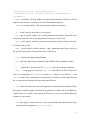
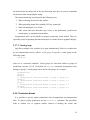
1.5.3 Menu commands
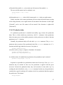
To display the menu click the right mouse button inside the lpfg window.
Figure 1 Lpfg menu
Step
Advances simulation to the next step. This may correspond to
more than one derivation step if parameter step in the animate
file is present and specifies a value greater than 1.
Run
Starts or resumes the animation.
Forever
Starts or resumes the animation. After the last frame is reached
the animation returns to the first frame and continues.
Stop
Stops the animation.
Rewind
Resets the animation to the first frame.
Don’t animate
Stops the animation and generates the image in the still mode
(performs the number of derivation steps as specified in the
7
derivation length statement).
Restore view
Resets rotation, zoom, pan, frustum and roll to the default
values.
Reset Æ Rotation
Resets rotation.
Reset Æ Zoom
Resets zoom.
Reset Æ Pan
Resets pan.
Reset Æ Roll
Resets roll.
Reset Æ Frustum
Resets frustum (not implemented yet).
Show axes
Turns on or off display of coordinate system axes in the lower
left corner.
Output Æ BMP
Creates image file filename.bmp containing the current state
of the window, where filename is the name of the L-system file.
Output Æ Rayshade
Creates a rayshade file.
Output Æ POV-Ray
Creates a POV-ray file.
Output Æ Postscript
Creates a postscript file filename.ps, where filename is the
name of the L-system file. All modules F are drawn as lines,
even if line style is set to cylinder. If line style is
polygon then modules F are drawn as lines of properly scaled
width. The only other modules supported are Circle and
Circle0. No other modules are visualized.
Output Æ Obj
Creates output file in the Alias/Wavefront .obj format.
Output Æ View
Creates a file called viewid.vw, where vw is the numeric id of
the current view window. The file contains a single view:
command (as used in the view file, see section 3.2), describing
the current view parameters.
View Æ view name
Opens the specified view window.
View Æ
Creates a file called winparams.cfg. This file contains a series
Save arrangement
of window: commands (as used in the view file, see section
3.2), one for every active view, with their current arrangement.
8
2 The L+C modeling language
L-system input files to lpfg use a new L-system-based modeling language, L+C. It is a
declarative language which combines L-system constructs (notably, modules and
productions) with the general-purpose programming language C++. L-system constructs
have syntax which is similar to the traditional notation of L-systems (used, for instance,
in cpfg); however, this syntax is also not too different from that of C++. The principle
advantage of this hybrid approach is that the expressive power of C++ can be used in
L+C programs; experience has shown that developing complex models is substantially
easier in L+C than in traditional L-system notation.
2.1 L-system file
A typical L-system program file has the following format:
#include <lpfgall.h>
derivation length: d;
// declarations of data structures
// declarations of functions
// module declarations
derivation length: n;
axiom: module_list;
// productions
All elements of a program can appear in any order except for the following
restrictions:
1) all elements referred to in a statement must be declared beforehand. Types used as
parameters of a module must be declared before the module is declared. Modules that
appear in an ignore or consider statement must be declared beforehand.
2) Productions are matched in the order in which they are declared.
2.1.1 Mandatory elements
Every L-system must include the statements derivation length and axiom.
2.1.2 Include files
The first line in the L-system is the #include statement. The lpfgall.h include file
includes the following header files:
•
memory.h and stdlib.h are standard C header files. They are required by the
code generated by the L2C translator.
9
•
lparams.h – This file contains the declarations and definitions of parameters
used by lpfg, the L2C translator, and the C++ code generated by the translator,
such as the maximum number of parameters per module, the maximum number of
modules in a production predecessor, and so on.
•
lintrfc.h – This file contains declarations and definitions that are used by lpfg
and the C++ code generated by the L2C translator, such as types used for
communication between the L-system and lpfg, predefined vector types, and
internal types relating to productions and context.
•
lsys.h – This file contains declarations and definitions required by the C++ code
generated by the L2C translator. These include definitions of some predefined
functions: Forward(), Backward(), etc.
•
stdmods.h contains the declarations of predefined modules.
lpfg standard header files should be treated the same way as the standard C header
files: they should never be changed or edited in any way. If they are altered, models
might not compile, stop working, or lpfg may hang or crash.
2.2 L+C language constructs
A typical L+C program consists of standard C++ declarations (such as data structures,
global variables, or function definitions) and L-system constructs. For an introduction to
C++ syntax, see a standard C++ textbook; the L-system-specific constructs are described
here.
2.2.1 Derivation length
The derivation length must be defined in all L+C files. It specifies the number of
derivation steps for the L-system:
derivation length: expression;
The expression must evaluate to an integer, though other than that there are no
restrictions on it. However, some care should be taken that the value is constant; the
expression may be evaluated more than once, and lpfg's behaviour is undefined if the
value changes.
10
2.2.2 Module declarations
L+C requires that all modules which are to be used in an L-system be declared. Many
standard modules are predefined (see section 2.3); the syntax for declaring new modules
is
module name(parameters);
Here name is the module's name, and parameters is a list of the types of the module's
parameters. For instance:
module A(int,int);
module B();
module C(float,data);
The module A has two parameters, both with type int; B has no parameters; and C has
two parameters, the first with type float, the second with some previously defined type
data. If a module has no parameters, it can also be declared omitting the parentheses:
module B;
All types (such as data above) must be defined before being used in the module
declaration. In addition, each type must be a single identifier; compound types such as
char* or unsigned int are not allowed. If you want to use these types, use a
typedef statement to give them single names:
typedef char* string;
typedef unsigned int uint;
Note also that, unlike function arguments, module parameters have no names; thus, the
declaration
module A(int id, int age);
is illegal. However, it is often useful to note the parameter names:
module A(int /* id */, int /* age */);
Unlike cpfg, a module name cannot be used twice, even with different types or
numbers of parameters.
11
2.2.3 Axiom
The axiom statement defines the L-system's axiom. Its syntax is:
axiom: module-string;
where the module-string is a sequence of modules. Some valid axioms are:
axiom: A(1,2) B() A(0,0);
axiom: A( idx*2, (int)(sin(x*M_PI)) );
If a module has no parameters, you may omit the parentheses:
axiom: A(1,2) B A(0,0);
2.2.4 ignore and consider
These statements have the following syntax:
ignore: module_names;
or
consider: module_names;
where module_names is a sequence of module names. Valid ignore or consider
statements include:
ignore: F P RollR;
consider: G A Circle;
Only one of ignore or consider may be used in an L+C program. They affect
which modules are considered in context matching when applying productions. By
default, all modules are considered when matching contexts. (More or less: see the
Appendix How productions are matched.) When an ignore statement is used, all
modules listed in it are ignored for the purposes of matching context. If a consider
statment is used, only those modules listed are considered in context matching.
SB and EB modules are always considered. Listing them in an ignore or
consider statement has no effect.
2.2.5 Control statements
There are four control statements which are called by lpfg while performing L-system
derivation. The statement Start is called before the string is initialized to the axiom; the
statement StartEach is called before each derivation step; the statement EndEach is
12
called after each derivation step; and the statement End is called after the final derivation
step. Any of these four control statements can be defined in the L+C program as
procedures, and they may contain any valid C++ statements. For instance, to maintain a
global variable steps equal to the current derivation step, you could define the control
statements:
int steps;
Start:
{
steps = 0;
}
EndEach:
{
steps++;
}
Note: the statement End is called after the final derivation step. This means that if you
are in Animate mode and stop or rewind the animation before it reaches the final
derivation step, the End statement is never called. If the End statement runs a vital
command (for instance, to close an output file), you should make sure that you let the
animation reach the final frame.
2.2.6 Productions
Productions define the way the structure defined by the L-system string develops over
time by specifying the fate of each module. A production definition has two parts: the
predecessor, declaring which module is being changed (the strict predecessor), and what
context it must be found in; and the production body, declaring how it changes in the next
derivation step:
predecessor:
{
production body
}
2.2.6.1 The predecessor
The predecessor of a production contains, at a minimum, the strict predecessor. This is
the module or sequence of modules which, if the production is applied, will be replaced
13
by new modules at the next derivation step. Valid productions containing only a strict
predecessor include:
F(x):
{...}
A(age,length) B():
{...}
Any parameters must be listed and given unique names, even if they are not used in
the production body. Also, unlike the axiom and produce statements, a module with
no parameters must be followed by parentheses ().
In addition to the strict predecessor, a production may also list a context to its left or
right (or both). These contexts must also be matched within the string for the production
to be applied, although only the strict predecessor will be replaced. The left context is set
to the left of the strict predecessor, and separated by a <; the right predecessor is to the
right, separated by a >. Some examples include:
A(ageL,lengthL) < A(age,length) > A(ageR,lengthR):
{...}
B() B() > B() B():
{...}
Note that, again, all parameters must be given unique names.
Finally, a production may list either a right or left new context. The new context is an
L-system construct new to lpfg. It lets you take advantage of the fact that the actual
computation of L-system derivations happens sequentially from one end of the string to
the other to transfer information from end to end in a single derivation step. Normally the
direction of derivation is from left to right ("forward"); the statements Forward() and
Backward() let you control this derivation direction. If the derivation direction is from
left to right, the new left context can be used; if the derivation direction is from right to
left, the new right context can be used.
These new contexts are set off from the strict predecessor by a << (for left context) or
>> (for right context). For example, the production
B() << D():
{...}
14
will match if the module B() exists in the new left context of the module D().
The new and old contexts can be combined, as in
A(age,length) < B() >> B():
{...}
which matches an A(x,y) in the old left context and a B() in the new right context.
Finally, note that a new-context production will never match if the derivation is going
in the wrong direction; a new right context will not match if the direction is left-to-right
("forward"), and a new left context will not match if the direction is right-to-left
("backward").
2.2.6.2 Production body
If a production predecessor is matched successfully, lpfg executes the production
body. This is a block which may contain any valid C++ statement. In the production
body, the names given to the module parameters in the predecessor act akin to function
parameters in a C++ function.
Normally, the production body will end with a produce statement. The produce
statement ends execution of the production body (like a return statement in a C++
function) and tells lpfg what the successor is. Its syntax is:
produce module_string;
where the module_string is a sequence of modules. For instance:
produce A(newAge,newLength);
produce B() A(x,length*12) B();
As with the axiom, if a module has no parameters, the parentheses may be omitted:
produce B A(x,length * 12) B;
In general, it is possible for a production to end in one of two ways. First, a produce
statement may be reached. In this case, the production is applied with the given
successor. Second, the production body may end execution in some other way: by
reaching the end of the block, or by a return statement. In this case, the production is
considered not applied, and lpfg will continue to look for a production that does apply to
the predecessor. For instance:
A(age,length):
15
{
if (age < 10)
produce A(age+1,length+dl);
}
A(age,length):
{
if(age >= 10)
produce B(length);
}
The first production will only be applied if the first parameter of the module A is less
than 10; otherwise, it will not be applied, and the second production will be tried,
following the usual application order for L-system productions. The second production
will only be applied if the first parameter is greater or equal to 10.
2.2.6.2.1 Alternative successors
It is important to note that a produce statement may be found anywhere in the
production body where a C++ statement is valid, and causes the production to be applied
with the given successor. Just as it is possible in C++ to have alternative return values, it
is possible in L+C to choose between alternative successors:
A(age,length):
{
if ( age < 10 )
produce A(age+1,length+dl);
else
produce B(length);
}
In this single production, both productions shown in the last section have been
combined into one. If the first parameter is less than 10, the first successor will be
produced; otherwise, the second successor will be produced.
2.2.6.2.2 Empty successor
A produce statement may be issued without a sequence of modules:
produce;
If this statement is reached in executing the production body, the production will be
applied with an empty successor; the strict predecessor will be removed from the string,
and will not be replaced. Note the difference between ending with a return statement,
16
in which case the production will not be applied, and an empty produce statement, in
which case the production is applied but produces nothing.
2.2.6.2.3 The nproduce statement
It is sometimes useful to build a production’s successor incrementally. The
nproduce statement specifies part of a successor, but, critically, does not end the
production. It syntax is like that of the produce statement:
nproduce module_list;
The nproduce statement adds the listed modules to the currently defined successor,
but does not end execution of the production. A subsequence produce statement will
add its own argument to the successor, then produce that successor. If the production
body ends without a produce statement, the production is not applied, and the partial
successor is ignored. For instance:
A(age,length):
{
for(int i = 0; i < age; i++)
nproduce B;
produce A(age+1,length);
}
An empty produce statement adds no more modules to the successor, but will still
produce the successor specified by nproduce statements.
2.2.6.3 Decomposition rules
While productions specify how a structure evolves over time, decomposition rules
specify how a structure is composed of substructures. After the axiom and every
derivation step, a decomposition step is performed. Decomposition is performed as long
as the string does not contain any modules that can be further decomposed, or the
maximum decomposition depth is reached. Syntactically, decomposition rules are very
similar to regular productions except for the following differences:
•
only one module is allowed in the strict predecessor, and
•
decomposition rules are always context-free.
17
When the statement decomposition: is present in the L-system it specifies that all the
following rules are decomposition rules, until the end of the source file or until a
production: or interpretation: statement is encountered. The statement maximum
depth: specifies the maximum decomposition depth. It must be placed in the global
scope after the decomposition: statement. The syntax of the maximum depth statement
is:
maximum depth: expression;
The default maximum decomposition depth is 1. An L-system may contain many
decomposition sections, but only one instance of the maximum depth statement
is allowed: it is applied to all decomposition rules in the program.
Decomposition rules can be recursive: the module in the strict predecessor can
appear in the successor. For example:
decomposition:
maximum depth: 6;
A(age,length):
{
if (length > 0)
produce F(1) A(age,length - 1);
}
Note: decomposition is internally implemented by a recursive call to a function. If the
maximum depth is a very large number the thread stack might overflow, causing lpfg to
crash.
2.2.7 Interpretation rules
Interpretation rules are syntactically very similar to decomposition rules. To specify
interpretation rules the interpretation: statement must be given. Like decomposition
rules, interpretation rules must have exactly one module in the strict predecessor and
must be context-free. A maximum
depth definition may be given after the
interpretation statement. As with decomposition rules, there may be only one
maximum depth definition, which applies to all of the interpretation rules in the
program. The default maximum depth is 1.
Interpretation rules are equivalent to “homomorphisms” in cpfg. They are executed
only during the interpretation of the string. Modules produced by interpretation rules are
18
not inserted into the string used in the next derivation step; they are used as commands
for the turtle when interpreting the string.
The interpretation step is performed in the following cases:
1. When redrawing the model in the window
2. When generating output file (rayshade, POVray, postscript)
3. When calculating the view volume.
4. After axiom and each derivation step, if any of the productions’ predecessors
contain query or communication modules
Interpretation rules can be helpful in properly expressing visual models. They are
especially useful in separating the functional aspect of a model from its graphical display.
2.2.7.1 Visual groups
lpfg allows multiple view windows to be open simultaneously. Each view window has
its own interpretation section, called a visual group. To specify a visual group use the
following syntax:
vgroup nn:
where nn is a numerical identifier. Visual groups are somewhat similar to groups of
productions (section 2.2.9.2). By default (no vgroup command) interpretation rules
belong to vgroup 0. Visual groups can be mixed with groups. For example:
interpretation:
group 0:
vgroup 0:
/* Interpretation
vgroup 1:
/* Interpretation
group 1:
/* Interpretation
vgroup 0:
/* Interpretation
rules here belong to group 0, vgroup 0 */
rules here belong to group 0, vgroup 1 */
rules here belong to group 1, vgroup 1 */
rules here belong to group 1, vgroup 0 */
2.2.8 Production blocks
It is possible to specify regular productions after decomposition and interpretation
rules. To specify regular productions use the production: statement. This possibility
leads to another way to organize models. Instead of dividing the model into
19
production, decomposition, and interpretation sections, all rules that
apply to one type of module can be grouped together. For example:
production:
A() : { … }
decomposition:
A() : { … }
interpretation:
A() : { … }
production:
B() > A() : { … }
decomposition:
B() : { … }
2.2.9 L-systems extensions
2.2.9.1 Ring L-systems
A ring L-system provides an alternate topology for the L-system string. The derivation
is performed as if the last module in the string and the first module in the string are
adjacent, so that the string forms a ring. Productions which are applied to the beginning
of the string have their left contexts matched against the end of the string, and
productions which are applied to the end of the string have their right contexts matched
against the beginning of the string. For example:
Axiom: A;
A() < A() > A() : { produce B; }
will yield the string B, and
Axiom: B C A;
C() < A() > B() : { produce D; }
will yield the string BCD.
To specify a ring L-system, include the statement
ring L-system: value;
where value is some nonzero value, or an expression returning a nonzero value.
2.2.9.2 Groups of productions
It is possible to specify alternate groups of productions and switch between them when
generating the model. By default, all productions, decompositions, and interpretation
rules belong to the default group, numbered 0. To specify productions for another group,
use the group statement:
20
group number:
where number is an integer constant. You can switch between groups any number of
times. The statement endgroup is equivalent to group 0: it ends the definition of the
current group, and returns to defining the default group.
When lpfg is started, the default group of productions is used. The function
void UseGroup(int grpid);
changes which group of productions is currently in use; it can be called at any time, but
will only take effect on the next derivation step.
The default group has a special property: if no production in the current group can be
applied to a symbol, the productions in the default group will be tried, even if it is not the
current group.
2.2.9.3 Interaction with the model
Lpfg makes it possible to interact with a running L-system model. The user can point
to an element of the model on the screen and click to insert a predefined module
(MouseIns or MouseInsPos) in the string immediately before the module pointed to
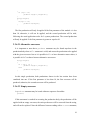
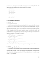
by the user. For example, if the current string is
F(1) SB Left(30) F(1) EB SB Right(30) F(1) EB
then the lpfg window will show a “Y” shape:
Click here
If the user clicks on the line as shown, the string will be modified:
F(1) SB Left(30) F(1) EB SB Right(30) MouseIns F(1) EB
Now, if the L-system contains the production
MouseIns() : { produce F(0.2) Cut; }
then it will be applied in the next derivation step and the string will become:
F(1) SB Left(30) F(1) EB SB Right(30) F(0.2) EB
21
This interaction thus simulates pruning.
To insert the module MouseIns press Ctrl and Shift and click with the left mouse
button. There is also MouseInsPos module that can be inserted by holding Alt and Ctrl
while left-clicking. MouseInsPos has two parameters:
module MouseInsPos(float, float);
The values of these parameters are the relative horizontal and vertical position of the
mouse on the screen when clicking. The first parameter has a value of 0 if the mouse is at
the left edge of the screen, increasing to 1 at the right. The second parameter has a value
of 0 at the top of the screen, increasing to 1 at the bottom.
2.3 Predefined functions
There are many functions and structures predefined by lpfg for controlling the
derivation of the L-system, accessing the system, and for general convenience.
2.3.1 Vector structures
lpfg provides four structures that represent vectors. The structures are:
struct V2f
{ float x, y; };
struct V3f
{ float x, y, z; };
struct V2d
{ double x, y; };
struct V3d
{ double x, y, z; };
These structures are used as parameters for some predefined modules. They can also
be used in the user’s code in the L-system. Additionally, if the preprocessor symbol
NOAUTOOVERLOAD is not defined before #include <lpfgall.h>, these structures
receive additional functionality: operators for addition, subtraction of two structures of
the same type, unary negation, multiplication and division of a vector by a scalar, dot
22
product, and assignment operators +=, -=, *=, and /=. In addition, cross product is
defined on V3f and V3d,with operator %.
V2f a(1.5, 2.0), b(0, 0.5);
V2f c = a + 2.5*b;
float x = a * b;
V3f d(1.2,2.3,0) , e(0,0.5,0.1);
V3f f = d % e;
Two further methods are defined:
f Length(); returns the vector’s length (as float or double, depending on the
structure).
void Normalize(); normalizes the vector. (This function’s behaviour is undefined if
the vector’s Length() is zero.)
void Set(x, y); sets the x and y components of a V2f or V2d; V3f and V3d have a
corresponding method Set(x, y, z).
Refer to the file lintrfc.h in the lpfg/include directory to see full definition of
these structures.
2.3.2 Controlling L-system derivation
void Forward()
This function specifies that the derivation of the string should be performed forward –
from left to right. This is the default.
void Backward()
This function specified that the derivation of the string should be performed backward
– from right to left.
Forward and Backward can be used anywhere in the code where it is legal to call a
function. They take effect on the next derivation step. In particular, if called in the
StartEach statement, they affect the immediately succeeding derivation step.
bool IsForward()
Returns the last derivation direction, as set by Forward or Backward. Note: this
function returns a variable set by Forward and Backward. Consequently, it may not
reflect the current derivation direction if it is changed during a derivation step.
23
void Environment(); void NoEnvironment().
These functions specify whether or not the “interpretation for environment step”
should be performed after the current derivation step. NoEnvironment turns the
environment off unconditionally.
void UseGroup(int);
Specifies current group of productions that should be used. See Table L-systems.
int CurrentGroup();
Returns the number of the current group. See Table L-systems.
void DisplayFrame();
Displays a frame of the animation at the current derivation step, when display on
request is on in the animation file. If display on request is off, this function
has no effect.
void Stop();
Stops the simulation. The End statement is executed after the current derivation step.
2.3.3 Manipulating views
To manipulate multiple views use the following functions:
void UseView(int vid);
opens or activates view identified by vid.
void CloseView(int vid);
closes the view identified by vid. If the view is not open, a warning message will be
printed.
The L-system can also access some of the current view parameters.
float
float
float
float
float
float
vvXmin(int
vvYmin(int
vvZmin(int
vvXmax(int
vvYmax(int
vvZmax(int
id);
id);
id);
id);
id);
id);
return the coordinates of bounding box of view number id.
float vvScale(int id);
returns the current projection scaling factor of view number id.
24
2.3.4 External access
void Printf(const char*, …).
This function is similar to the standard C function printf. Its use is recommended
over the printf for the following reasons:
•
Output generated by printf is not stored in the lpfg.log file.
•
In the future releases lpfg might not be connected to any console, but instead
provide its own output window (like cpfg’s message log). In that case, output of
printf would not be visible anywhere.
void Run(const char* cmnd);
This function works like standard C system function, except that it does not wait for
the called process to terminate. It is equivalent to adding a ‘&’ at the end of the command
in a Unix shell.
2.3.5 Curves and functions
float func(int id, float x)
This function returns the value of function id in the function-set file (if one is
specified on the command line). The parameter id must be in the range [1, num of
functions]. The second parameter is the x value whose y value is requested. x must be in
the range [0, 1].
If the parameter id is incorrect (outside the range), the value 0 is returned and a
warning message is printed. If the parameter x has invalid value then:
•
if x < 0 then func(id, 0) is returned, or
•
if x > 1 then func(id, 1) is returned
In the case of invalid value of x, a warning message is printed in Verbose mode only.
When calling the pre-processor lpfg #defines macros with the names of the functions
in the .fset file. The values correspond to the numerical identifiers of the functions. For
example: if the first function in the .fset file is named Func1 then the following macro is
defined: #define Func1 1.
Consequently it is possible to call func using the identifier Func1 instead of the
integer literal 1: float y = func(Func1, 0.5);
25
float curveX(int id, float t);
float curveY(int id, float t);
float curveZ(int id, float t);
V2f curveXY(int id, float t);
V3f curveXYZ(int id, float t);
These functions return the coordinates of the curve defined in a contour-set file. id is
the number of the curve, and t is the arc-length parameter. When calling the preprocessor, lpfg will #define numerical values for the names of the curves, just as for
functions (see above).
void curveScale(int id, float x, float y, float z);
Scales the curve identified by id by the factors x, y, and z.
void curveSetPoint(int id, int p, float x, float y, float z);
Assigns the pth control point of curve id the position (x,y,z). After this function
is used the curve must be recalculated by a call to
void curveRecalculate(int id);
in order for the curveX|Y|Z functions to return the proper values.
void curveReset(int id);
Resets the curve to the state defined in the .cset file. The file is not re-read.
2.3.6 Other predefined functions
float ran(float range)
Generates a pseudorandom number uniformly distributed in the range [0, range).
2.4 Predefined modules
The following table lists all of the predefined modules.
Module
Description
Equivalent
in cpfg
Modeling branching structures
SB()
EB()
Cut()
Starts a new branch by pushing the current state of the turtle
onto the turtle stack.
Ends a branch by popping the state of the turtle from the
turtle stack.
Cuts the remainder of the current branch. If the derivation
direction is from left to right (“forward”) then when this
[
]
%
26
direction is from left to right (“forward”), then when this
module is detected in the string during a derivation, it and all
following modules up to the closest unmatched EB module
are ignored for derivation purposes. If no unmatched EB
module can be found, symbols are ignored until the end of the
string. This symbol has no effect if the derivation direction is
from right to left (“backward”).
Changing position and drawing
Turtle commands
F(float /*d*/)
F(d)
G(float /*d*/)
Moves forward a step of length d and draws a line segment
from the original position to the new position of the turtle. If
the polygon flag is on (see modules SP, PP and EP), the
final position is recorded as a vertex of the current polygon.
Moves forward a step of length d. No line is drawn. If the
polygon flag is on, the final position is recorded as a vertex
of the current polygon.
Same as F, except that it does not create polygon vertices
g(float /*d*/)
Same as f, except that it does not create polygon vertices
g(d)
MoveTo
(float /*x*/,
float /*y*/,
float /*z*)
MoveTo3f
(V3f /*p*/)
MoveTo3d
(V3d /*p*/)
MoveTo2f
(V2f /*p*/)
MoveTo2d
(V2d /*p*/)
Sets the turtle’s position to (x, y, z).
@M(x,y,z)
Moves the turtle to point p.
@M
Same as MoveTo3f.
@M
Moves the turtle to point p. The z coordinate is assumed to
be 0.
Same as MoveTo2f.
@M
f(float /*d*/)
F(d)
G(d)
@M
Affine geometry support
Line3f
(V3f /*p1*/,
V3f /*p2*/)
Line3d
(V3d /*p1*/,
V3d /*p2*/)
Line2f
(V2f /*p1*/,
V2f /*p2*/)
Line2d
(V2d /*p1*/,
V2d /*p2*/)
LineTo3f
(V3f /*p*/)
Draws a line from the point p1 to the point p2. After the
interpretation of the module, the turtle position is equal to
p2. Heading, left and up vectors are not changed. If the
distance between p1 and p2 is less than ε (a constant set to
10-5), the module is ignored.
Same as Line3f.
Same as Line3f, except that the z coordinate is assumed
to be 0.
Same as Line2f.
Draws a line from the current turtle position to the point p.
After the interpretation of the module the turtle position is
equal to p. Heading, left and up vectors are not changed. If
27
LineTo3d
(V3d /*p*/)
LineTo2f
(V2f /*p*/)
LineTo2d
(V2d /*p*/)
LineRel3f
(V3f /*p*/)
LineRel3d
(V3d /*p*/)
LineRel2f
(V2f /*p*/)
LineRel2d
(V2d /*p*/)
the distance from the current position to p is less than ε, the
module is ignored.
Same as LineTo3f.
Same as LineTo3f, except that z coordinate is assumed to
be 0.
Same as LineTo2f.
Draws a line from the current turtle position to the point
p2 = (turtle position) + p. After the interpretation of the
module the turtle position is equal to p2. Heading, left and
up vectors are not changed. If the length of vector p is less
than ε, the module is ignored.
Same as LineRel3f.
Same as LineRel3f, except that z coordinate is assumed
to be 0.
Same as LineRel2f.
Turtle rotations
Left
(float /*a*/)
Right
(float /*a*/)
Up(float /*a*/)
Turns left by angle a around the U axis.
+(a)
Turns right by angle a around the U axis.
-(a)
Pitches up by angle a around the L axis.
^(a)
Down
(float /*a*/)
RollL
(float /*a*/)
RollR
(float /*a*/)
TurnAround()
Pitches down by angle a around the L axis.
&(a)
Rolls left by angle a around the H axis.
\(a)
Rolls right by angle a around the H axis.
/(a)
Turns around 180 degrees around the U axis. This is
equivalent to Left(180) or Right(180). It does not roll
or pitch the turtle.
Sets the heading vector of the turtle to hx, hy, hz and the up
vector to ux, uy, uz. The left vector is set to the cross
product of the new H and U. The values do not need to
specify normalized vectors. The module is ignored if any of
the following is true:
a) (hx,hy,hz) specify a vector of length less than ε
b) (ux,uy,uz) specify a vector of length less than ε
c) Length of the cross product of new H and U is less than ε.
Rolls the turtle around the H axis so that H and U line in a
common vertical plane, with U closer to up than down.
|
SetHead
(float /*hx*/,
float /*hy*/,
float /*hz*,
float /*ux*/,
float /*uy*/,
float /*uz*)
RollToVert()
@R
(hx,hy,hz,
ux,uy,uz)
@v
Changing turtle parameters
IncColor()
Increases the current colour index or material index by one.
;
DecColor()
Decreases the current colour index or material index by one.
,
28
SetColor
(int /*n*/)
Sets the current colour index or material index to n. If n is
less than 1 or greater than 255, the module is ignored.
;(n)
SetWidth
(float /*v*/)
Sets the current line width to v. If v≤0, the module is
ignored.
#(n)
,(n)
!(n)
Drawing circles and spheres
Circle
(float /*r*/)
Sphere
(float /*r*/)
Circle0()
Draws a circle in the XY plane, centered at the current turtle
position and with radius r.
Draws a sphere of radius r at the current turtle position.
@o(d)
Draws a circle of diameter equal to the current line width.
@o
Sphere0()
Draws a sphere of diameter equal to the current line width.
@O
@O(d)
(Note that in cpfg, the parameters of the modules @o and @O specify the diameter, not the radius.)
Drawing other shapes
Rhombus(float
/*length*/,
float /*width*/)
Triangle(float
/*width*/,
float
/*height*/)
SP()
Draws a rhombus in the HL plane.
Starts a polygon.
{
EP()
Ends a polygon.
}
PP()
Sets a polygon vertex. There may be at most 16 vertices in a
polygon.
Draws three lines of unit length at the turtle’s current
position. The red line represents the heading vector, the green
line represents the left vector, and the blue line represents the
up vector. This module is useful for model debugging.
.
Orient()
Draws an isosceles triangle.
Drawing bicubic parametric surfaces
Surface
(int /*id*/,
float /*scale*/)
Surface
(int /*id*/,
float /*xscale*/,
float /*yscale*/,
float /*zscale*/)
InitSurface
(int /*id*/)
Draws the predefined surface identified by the identifier
id at the current location and orientation. The surface is
uniformly scaled by the factor scale. Surfaces are
specified in the view file. The first surface specified in the
view file has id=0. Like functions and contours, surface
names are #defined by lpfg.
Draws the predefined surface identified by the identifier
id at the current location and orientation. The surface is
scaled independently along the X, Y, and Z axes by
xscale, yscale, and zscale, respectively.
~
Initializes the L-system-defined surface with id id.
Currently, there is only one surface allowed, so the
@PS
~
29
SurfacePoint
(int /*id*/,
int /*p*/,
int /*q*/)
DrawSurface
(int /*id*/)
parameter is ignored.
Sets the (p,q) control point (with 0 ≤ p, q < 4) of the Lsystem-defined surface with id id to the current turtle
position. The first parameter is ignored.
Draws the L-system defined surface with id id. The
parameter is currently ignored.
@PC
@PD
Drawing generalized cylinders
CurrentContour
(int /*id*/)
Sets the contour specified by id as the current contour for
generalized cylinders. If id equal to 0 is specified then the
default contour (circle) is used.
Starts a generalized cylinder at the current turtle position.
@#(id)
Specifies a control point on the central line of the generalized
cylinder.
@Gc(n) (but
EndGC()
Ends a generalized cylinder.
@Ge
CurrentContours
(int /*id1*/,
int /*id2*/,
float /*blend*/)
Sets the current contour to be an interpolated contour
between id1 and id2 with blending coefficient blend. At
blend==0, the contour is id1; at blend==1, the contour is
id2.
Scales the contour independently by p (left) and q (up)
StartGC()
PointGC()
ScaleContour
(float /*p*/,
float /*q*/)
ContourSides
(int /*sides*/)
CurrentTexture
(int /*txtid*/)
TextureVCoeff
(float /*v*/)
@Gs
not exactly)
Specifies how many sides generalized cylinders will be
drawn with. If this module is interpreted outside a generalized
cylinder (that is, before StartGC and after EndGC, if any),
then it affects all subsequent generalized cylinders. If it is
interpreted within a generalized cylinder, it is ignored.
Specifies which texture should be used to texture map
generalized cylinders. Calling this function with txtid = 0
will turn off texture mapping of generalized cylinders.
Sets the texture’s v coordinate scaling factor. If v = 1, then
when the turtle moves forward by one unit, the generalized
cylinder will be textured by the entire texture. If, for instance,
you want to texture a cylinder 10 units long, then setting the v
scaling factor to 0.1 will map the texture exactly onto the
cylinder. If the texture’s v coordinate exceeds one, then the
texture wraps (sets v to 0).
Tropism
SetElasticity
(int /*id*/,
float /*v*/)
IncElasticity
(int /*id*/)
DecElasticity
(int /*id*/)
Sets the elasticity parameter of tropism id to v.
@Ts
Increments the elasticity parameter of tropism id by the
elasticity step parameter of the tropism.
Decrements the elasticity parameter of tropism id by the
elasticity step parameter of the tropism
@Ti
@Td
30
Simple tropism
Elasticity
(float /*v*/)
Sets the elasticity to v.
_
(underscore)
Query and communication modules
GetPos
(float /*x*/,
float /*y*/,
float /*z*/)
GetHead
(float /*x*/,
float /*y*/,
float /*z*)
GetLeft
(float /*x*/,
float /*y*/,
float /*z*)
GetUp
(float /*x*/,
float /*y*/,
float /*z*)
En(float …)
MouseIns()
MouseInsPos
(float /*xr*/,
float /*yr*/)
?P(x,y,z)
Queries the current turtle position. If any query module is
present in the predecessor of any production in the Lsystem, a special interpretation step is performed after each
generate step, when productions are applied. The string is
interpreted even if no drawing occurs. During the
interpretation the three parameters of the module are set to
the x, y and z coordinates of the current turtle position.
Queries the current turtle heading vector.
?H(x,y,z)
Queries the current turtle left vector.
?L(x,y,z)
Queries the current turtle up vector.
?U(x,y,z)
Communication modules used to send and receive
environmental information. There are different modules for
different numbers of parameters: E1(float), E2(float,float),
E3(float,float,float), and so on.
When the user holds Ctrl and Shift and left clicks on a
module in the simulator window, the MouseIns module
is inserted immediately before the clicked-on module in the
string.
When the user holds Ctrl and Alt and left clicks on a
module in the simulator window, the MouseInsPos
module is inserted immediately before the clicked-on
module in the string. The parameters give the relative
position of the mouse on the screen while clicking: xr is 0
at the left edge of the screen, increasing to 1 and the right
edge; yr is 0 at the top of the screen, increasing to 1 at the
bottom.
?E(v)
Miscellaneous
Label(Text str)
Prints the string str in the drawing window at the current
turtle location. Text is a datatype defined in
lintrfc.h as const char*.
@L(str)
31
3 Other input files
3.1 Animation parameters file
Command
first frame: n
last frame: n
swap interval: t
step: n
double buffer: on|off
clear between frames:
on|off
hcenter between frames:
on|off
scale between frames:
on|off
New view between frames:
on|off
display on request:
on|off
frame numbers:
consecutive|stepno
Comments
Derivation step to be interpreted as the first frame. Default is 0.
Note: in cpfg, the first frame defaults to 1. This is why Rewind in
cpfg rewinds to the first derivation step, while in lpfg Rewind
rewinds to axiom.
Derivation step to be interpreted as the last frame. Default is the
number of derivation steps.
Minimum time interval between frames.
Number of derivation steps between drawing of frames. Default is 1
Specifies if the double buffer mode should be used. Default is on.
Specifies whether to clear the screen between frames. Default is on.
Specifies whether model should be horizontally centered between
frames. Default is off.
Specifies whether the model should be scaled to fit in the lpfg
window between frames. Default is off.
Currently has no effect.
If “on”, then when running an animation, only the first and last
frame are displayed automatically. To display a frame, the L-system
must call the function DisplayFrame(). This makes it possible to
skip drawing frames which do not advance time, but perform other
calculations. If “off” (the default), then frames are displayed
according to the “step” parameter.
Specifies the way the frames are numbered when the “Recording”
menu command is checked. If “consecutive” (the default), each
file’s number reflects the frame number, not the derivation step. If
this parameter is set to “stepno”, the number in the filename is the
derivation step number.
3.2 Draw/view parameters file
Drawing and viewing parameters are stored in the view file. This file can have
extension .v or .dr. The view file is preprocessed by the C++ preprocessor; therefore,
the use of comments (both C style /* … */ and C++ style //), as well as #defines,
#ifs, and all other standard preprocessor directives are allowed. The commands are
interpreted in the order in which they appear in the file. If there are two or more
commands that specify the same parameter, the last one takes precedence. This does not
32
apply to commands that specify new set of parameters every time they appear (e.g. lights,
tropisms). Every command must be contained on a single line.
Command
Comments
Setting the view
projection:
parallel | perspective
scale factor: s
scale: s
min zoom: v
max zoom: v
line style: style
front distance: x
back distance: x
regenerate view:
on | off | triggered
view: id rotx roty roll
scale panx pany panz
window: name left top
width height
Default is parallel.
s specifies the size of the final image on the screen. 1.0 corresponds
to full size. Default is 0.9. Either scale or scale factor may be used;
they are equivalent.
v specifies the minimum value of zooming factor (see Interactive
view manipulation). Default is 0.05.
v specifies the maximum value of zooming factor (see Interactive
view manipulation). Default is 50.
style must be one of the following: pixel, polygon or
cylinder. Default is pixel.
x specifies the distance to the front clipping plane
x specifies the distance to the back clipping plane
Defaults to off. If on, the L-system string is regenerated (the
simulator rewinds to the axiom and performs derivations again)
every time the view changes (through rotation, zoom, or pan). If
triggered, the string is regenerated after the user completes each
view change (after the user releases the mouse button). (triggered is
currently the same as on.)
Defines the view transform to be used for the view window with id
id.
Declares that the window with the given name should be placed
with its top left corner at relative position (left,top) within the main
lpfg window, with relative width and height width and height. The
views will be numbered in the order in which they appear in the
view file, and the name name will be #defined as the view
number, so that the L-system can contain commands like:
UseView(Plant);
vgroup Graph:
Rendering parameters
z buffer: on|off
render mode: mode
light: command1 command2
…
Default is off.
Mode must be one of the following: filled, wireframe or
shaded. Default is filled.
Each command must be one of the following:
O: x y z origin of point light source
V: x y z vector of directional source
A: r g b ambient
D: r g b ambient
S: r g b specular
P: x y z e c spotlight with the direction (x,y,z), exponent e,
cutoff angle c
T: c l q attenuation factors.
Up to 8 lights can be specified. (8 is the minimum number of lights
that must be supported according to the OpenGL specifications.)
33
contour sides: sides
Specifies the number of sides that will be drawn on generalized
cylinders. This command affects all generalized cylinders in the
model; however, it is overridden by either the ContourSides
module or the contour-specific “samples” parameter.
Other commands
surface: filename txidopt
texture: filename
tropism: command1 …
torque: command1 …
winfont: font size [bi]
stropism: x y z, e
filename is the filename of a surface (.s) file. txid, if present,
specifies the identifier of the texture associated with the surface. See
the description of the module Surface in Predefined modules.
Note: this command may be dropped in a future version when the
surface gallery is introduced.
filename specifies the image file that contains the texture. Both
width and height of the image must be powers of 2. Textures are
indexed starting at 0. Currently only SGI RGB files are supported.
Each command must be one of the following:
T: x y z tropism vector (required)
A: a angle. Default is 0.
I: x intensity. Default is 1
E: e elasticity. Default is 0
S: de elasticity step. Default is 0.
Any number of tropisms can be specified in the view file.
Each command must be one of the commands valid for tropism
except for A.
Specifies the font to be used for the module Label. Font is the
name of the font. If the name consists of more than one word (e.g.
Times New Roman) it should be enclosed in the quotation marks
(“Times New Roman”). Size specifies the font size in pixels.
Optional b and i flags specify bold and italic respectively.
Specifies the direction and elasticity of the tropism. This is the “oldstyle tropism” or “simple tropism” as introduced in cpfg by Jim
Hanan.
3.3 Environment parameters file
The environment parameters file has extension .e. It is read in by both lpfg and the
environmental program, and defines how they should communicate.
Command
executable: command
communication type:
pipes|sockets|memory|files
following module: on|off
turtle
turtle
turtle
turtle
position: format
heading: format
left: format
up: format
Remarks
Specifies the environmental process’s executable, together with
its optional command line parameters
Ignored. The only communication supported in the current
version is files.
Defines whether the module following the communication
module is sent to the environmental process. Default is off. If
the following module has parameters, they must all be floats.
printf-like format string used when sending turtle parameters. All
are optional, but most environmental programs will require at
least the turtle position.
For example:
34
turtle line width: format
turtle scale factor: format
verbose: on|off
Turtle position: P: %f %f %f
Verbose mode generates additional information about the details
of the communication
3.4 Miscellaneous input files
All of these file formats are described in the CPFG User’s Manual.
3.4.1 Colourmap file
Specifies 256 colours. Colourmap mode is used to create schematic images. See also
material file.
3.4.2 Material file
Specifies 256 materials. Materials are specified by the following components: ambient
colof, diffuse color, specular color, emission color, specular exponent, and transparency.
See the OpenGL documentation for further explanation. Material mode is used to create
realistic images.
3.4.3 Surface file
Specifies surfaces composed of one or more Bézier patches.
3.4.4 Function-set file
Specifies functions of one variable. The functions are defined as B-spline curves
constrained in such a way that they assign exactly one y to every x in the normalized
function domain [0, 1].
3.4.5 Contour-set file
Specifies contours defined as planar B-spline curves. The curves are considered as
cross-sections of generalized cylinders.
3.4.6 Textures
Currently the only supported format of textures is SGI RGB. Textures in the RGB
format may contain Alpha (transparency) channel.
35
4 Appendix: How productions are matched
When rewriting the string it is necessary to determine which production must be
applied to each module in the string. The process of determining the applicable
production is called production matching. For every module in the string, productions are
checked for matching. The productions are checked in the order in which they are
specified in the L-system.
For a production to match, all three components of the predecessor (left context, strict
predecessor and right context) must match. The rules for matching each of these
components are different. This is because the L-system string is a means of representing
branching structures and symmetric operations on the string do not (in general)
correspond to symmetric operations on the branching structure.
This section contains a detailed explanation of rules that control the process of
production matching. The notation used here utilizes symbols [ and ] to denote beginning
of branch and end of branch (modules SB and EB in lpfg).
When the strict predecessor is compared with the contents of the string in the current
position in order for it to match the modules in the strict predecessor have to match
exactly the modules in the string.
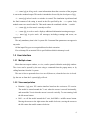
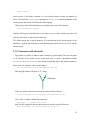
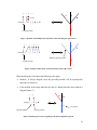
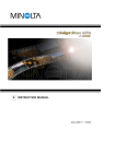
When matching the right context and a module in the context is not the same as
module in the string the following rules apply:
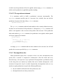
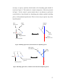
•
If a module in the string is [ and the module expected is not [ then the branch is
skipped. This rule reflects the fact that modules may be topologically adjacent,
even though in the string representation of the structure the two modules may be
separated by modules representing the lateral branch B (see Figure 2).
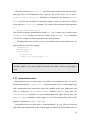
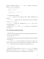
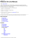
•
When a branch in the right context ends (with a right bracket) then the rest of the
branch in the string is ignored by skipping to the first unmatched ]. This rule also
reflects the topology of the branching structure, not its string representation. For
example in Figure 3, module C is closer to A than D.
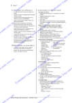
•
If multiple lateral branches start at a given branching point, then the predecessor
in Figure 3 would check the first branch (see Figure 4). To skip a branch it is
36
necessary to specify explicitly which branch at the branching point should be
tested (see Figure 5). This notation is a simple consequence of the rule presented
in Figure 3. In the current L-system notation there is no shortcut to specify the
second, third etc. lateral branch in a branching point without explicitly including
pairs [ ] in the production predecessor. There is also no way to specify “any of the
lateral branches”.
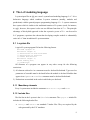
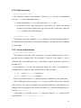
Strict
predecessor
Right
context
Skipped
branch
A > C
B
C
Right
context
String: A [ B ] C
Skipped branch
Strict
predecessor
A
Current position
Figure 2 Matching right context, lateral branches are implicitly ignored
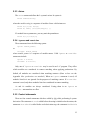
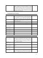
Ignored part
of the branch
A > [ B ] C
D
B
Right
context
C
String: A [ B D ] C
Rest of the branch
ignored
Current position
A
Figure 3 Matching right context, remainder of lateral branch is implicitly ignored
37
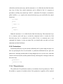
A > [ B ] D
C
D
No match
B
String: A [ C ] [ B ] D
A
Current position
Figure 4 Problem with multiple lateral branches when matching the right context
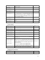
A > [ ] [ B ] D
String: A
C
D
B
[ C ] [ B ] D
Branch explicitly ignored
Current position
A
Figure 5 Explicit enumeration of lateral branches in the right context
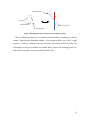
When matching the left context the following rules apply:
•
Module [ is always skipped, since the preceding module will be topologically
adjacent (see Figure 6).
•
If the module in the string indicates the end of a branch then the entire branch is
skipped (Figure 7).
C < A
String: C
A
B
[ A ] B
C
Ignored module
Left context
Current position
Figure 6 Matching left context, beginning of the branch implicitly ignored
38
Ignored branch
A
C < B
String: C
B
[ A ] B
C
Ignored branch
Left context
Current position
Figure 7 Matching left context, lateral branches implicitly ignored
The rule illustrated in Figure 6 is a pronounced manifestation of asymmetry in the left
context – right context relationship: module C is left context of both A and B. But C’s right
context is B (unless [ ] delimiters are used explicitly). The relation of the left context can
be thought of as the parent module: the module before (below) the branching point. It is
then natural to say that C is parent module for both A and B.
39