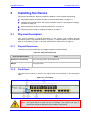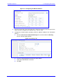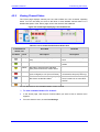
1
Mediant™ 800 MSBG Multi‐Service Business Gateway SIP Protocol Installation Manual Version 6.2 December 2010 Document # LTRT‐10204 Installation Manual Contents Table of Contents 1 Introduction......................................................................................................... 9 2 Installing the Device ......................................................................................... 11 2.1 Physical Description ...............................................................................................11 2.1.1 Physical Dimensions ............................................................................................... 11 2.1.2 Front Panel.............................................................................................................. 11 2.1.3 Rear Panel .............................................................................................................. 13 2.2 Unpacking the Package Contents ..........................................................................14 2.3 Mounting the Device ...............................................................................................15 2.3.1 Desktop Mounting ................................................................................................... 15 2.3.2 19-Inch Rack Mounting ........................................................................................... 16 2.3.2.1 Using a Pre-installed Rack Shelf ............................................................. 16 2.3.2.2 Using Mounting Brackets......................................................................... 17 2.4 Cabling the Device .................................................................................................18 2.4.1 Grounding the Device ............................................................................................. 19 2.4.2 Connecting to WAN ................................................................................................ 20 2.4.2.1 Gigabit Ethernet Copper Cabling............................................................. 20 2.4.2.2 T1 WAN DSU/CSU Cabling..................................................................... 21 2.4.2.3 SHDSL WAN Cabling .............................................................................. 22 2.4.3 Connecting to LAN .................................................................................................. 23 2.4.4 Connecting to FXS/FXO Interfaces......................................................................... 24 2.4.5 Connecting to Analog Lifeline Phone ...................................................................... 26 2.4.6 Connecting to ISDN BRI Lines................................................................................ 27 2.4.7 Connecting to E1/T1 Trunks ................................................................................... 28 2.4.8 Connecting the OSN Server ................................................................................... 28 2.4.8.1 Important Notes when Installing CentOS Ver. 4.7................................... 30 2.4.9 Connecting the Serial Interface to a PC ................................................................. 31 2.4.10 Powering up the Device .......................................................................................... 32 2.5 Maintenance ...........................................................................................................33 2.5.1 Replacing the Power Fuse ...................................................................................... 33 3 Configuring the Device .................................................................................... 35 3.1 Initial Web Interface Access ...................................................................................35 3.2 Basic Setup Configuration ......................................................................................37 3.2.1 VoIP and Data-Routing Functionalities ................................................................... 37 3.2.1.1 Assigning LAN IP Addresses................................................................... 37 3.2.1.2 Configuring Data-Routing DHCP Server ................................................. 39 3.2.1.3 Assigning Data-Routing WAN IP Address ............................................... 40 3.2.1.4 Configuring Data-Routing Quality of Service........................................... 42 3.2.1.5 Enabling Remote HTTP/S Web Management......................................... 49 3.2.2 VoIP-only Functionality ........................................................................................... 49 3.3 Configuring Router and SIP Call Routing ...............................................................51 3.4 Saving Configuration and Resetting the Device .....................................................51 3.5 Changing Login User Name and Password ...........................................................52 3.6 Backing Up and Restoring Configuration ...............................................................53 3.7 Restoring Factory Default Settings .........................................................................54 3.8 Upgrading the Device .............................................................................................55 3.8.1 Upgrading Firmware ............................................................................................... 55 3.8.2 Loading ini and Auxiliary Files ................................................................................ 58 Version 6.2 3 December 2010 Mediant 800 MSBG 4 Monitoring the Device ...................................................................................... 59 4.1 Front-Panel LEDs ...................................................................................................59 4.2 Web Interface .........................................................................................................60 4.2.1 Viewing Alarms ....................................................................................................... 60 4.2.2 Viewing Channel Status .......................................................................................... 61 4.2.3 Viewing Data-Routing Information .......................................................................... 62 Installation Manual 4 Document #: LTRT-10204 Installation Manual Contents List of Figures Figure 1-1: Summary of Installation Steps............................................................................................... 9 Figure 2-1: Front Panel .......................................................................................................................... 11 Figure 2-2: Rear Panel .......................................................................................................................... 13 Figure 2-3: Rubber Foot Attached to Underside of Device.................................................................... 15 Figure 2-4: Peeled-off Rubber Foot ....................................................................................................... 15 Figure 2-5: Mounting Bracket (Right)..................................................................................................... 17 Figure 2-6: Attaching the Mounting Brackets ........................................................................................ 17 Figure 2-7: Earthing the Device ............................................................................................................. 19 Figure 2-8: Connecting the WAN Port ................................................................................................... 20 Figure 2-9: Connecting the T1 WAN DSU/CSU Port............................................................................. 21 Figure 2-10: RJ-48c T1 WAN Connector Pinouts.................................................................................. 21 Figure 2-11: Connecting the SHDSL WAN Port .................................................................................... 22 Figure 2-12: Connecting the LAN Ports ................................................................................................. 23 Figure 2-13: Connecting FXS and FXO Ports (Example Hardware Configuration 4 FXS/4 FXO) ........ 25 Figure 2-14: RJ-11 Connector Pinouts .................................................................................................. 25 Figure 2-15: Cabling FXS Lifeline .......................................................................................................... 26 Figure 2-16: RJ-11 Connector Pinouts for FXS Lifeline ........................................................................ 26 Figure 2-17: RJ-45 Connector Pinouts for BRI Ports ............................................................................ 27 Figure 2-18: Cabling BRI Ports .............................................................................................................. 27 Figure 2-19: RJ-48c Connector Pinouts for E1/T1 ................................................................................ 28 Figure 2-20: Cabling OSN Server Ports ................................................................................................ 29 Figure 2-21: RS-232 Cable Adapter ...................................................................................................... 31 Figure 2-22: Cabling the Power ............................................................................................................. 32 Figure 2-23: Replacing the Power Fuse ................................................................................................ 33 Figure 2-24: Extracted Power Fuse ....................................................................................................... 34 Figure 3-1: Login Screen ....................................................................................................................... 36 Figure 3-2: Steps for Configuring VoIP and Data-Routing Functionalities ............................................ 37 Figure 3-3: Multiple Interface Table Page ............................................................................................. 38 Figure 3-4: Connections Page ............................................................................................................... 39 Figure 3-5: Defining LAN Data-Routing IP Address .............................................................................. 39 Figure 3-6: Configuring the DHCP Server ............................................................................................. 40 Figure 3-7: Configuring the WAN IP Address ........................................................................................ 41 Figure 3-8: Routing Tab ......................................................................................................................... 41 Figure 3-9: Traffic Shaping Page ........................................................................................................... 42 Figure 3-10: Selecting Device for Traffic Shaping ................................................................................. 42 Figure 3-11: Defining Traffic Shaping .................................................................................................... 43 Figure 3-12: Adding Shaping Class Name (for VoIP Tx Traffic) ............................................................ 43 Figure 3-13: Defining Shaping Class (for VoIP Tx Traffic) .................................................................... 44 Figure 3-14: Configured Traffic Shaping for Total WAN and VoIP Bandwidth ...................................... 44 Figure 3-15: Match Rules Page ............................................................................................................. 45 Figure 3-16: QoS Output Traffic Matching Rules .................................................................................. 46 Figure 3-17: Defining Incoming SIP Ports ............................................................................................. 46 Figure 3-18: Defining SIP Ports (e.g. TCP) ........................................................................................... 47 Figure 3-19: Traffic Matching Rule for Received SIP Signaling Traffic ................................................. 47 Figure 3-20: Matching Rule for Received RTP Traffic ........................................................................... 48 Figure 3-21: Traffic Matching Rule for WAN Tx/Rx RTP and SIP Signaling ......................................... 48 Figure 3-22: Defining WAN HTTP Port .................................................................................................. 49 Figure 3-23: Removing Data-Routing Connection Interface ................................................................. 49 Figure 3-24: Multiple Interface Table for Network without VLANs ......................................................... 50 Figure 3-25: Multiple Interfaces with VLANs ......................................................................................... 50 Figure 3-26: Defining VLANs per LAN Port ........................................................................................... 50 Figure 3-27: Maintenance Actions Page ............................................................................................... 51 Figure 3-28: WEB User Accounts Page (for Users with 'Security Administrator' Privileges) ................ 52 Figure 3-29: Configuration File Page ..................................................................................................... 53 Figure 3-30: Start Software Upgrade Wizard Screen ............................................................................ 56 Figure 3-31: End Process Wizard Page ................................................................................................ 57 Version 6.2 5 December 2010 Mediant 800 MSBG Figure 3-32: Load Auxiliary Files Page .................................................................................................. 58 Figure 4-1: Current Alarms in Active Alarms Page ................................................................................ 60 Figure 4-2: Home Page Displaying Color-Coded Icons......................................................................... 61 Figure 4-3: Connection Statistics Page ................................................................................................. 62 List of Tables Table 2-1: Physical Dimensions ............................................................................................................ 11 Table 2-2: Front-Panel Description ........................................................................................................ 12 Table 2-3: Rear-Panel Description ........................................................................................................ 13 Table 2-4: RJ-45 Connector Pinouts ..................................................................................................... 20 Table 2-5: RJ-45 Connector Pinouts for SHDSL ................................................................................... 22 Table 2-6: RJ-45 Connector Pinouts for GbE/FE with PoE ................................................................... 24 Table 2-7: Recommended Fuse Manufacturers .................................................................................... 33 Table 3-1: Default LAN VoIP and Management IP Address ................................................................. 35 Table 3-2: Default LAN Data-Routing IP Address ................................................................................. 38 Table 4-1: LEDs Description .................................................................................................................. 59 Table 4-2: Color-Coded Trunk/Channel Status Icon ............................................................................. 61 Installation Manual 6 Document #: LTRT-10204 Installation Manual Notices Notice This Installation Manual describes the hardware installation and quick configuration setup for AudioCodes Mediant 800 MSBG Multi-Service Business Gateway. Information contained in this document is believed to be accurate and reliable at the time of printing. However, due to ongoing product improvements and revisions, AudioCodes cannot guarantee accuracy of printed material after the Date Published nor can it accept responsibility for errors or omissions. Before consulting this document, check the corresponding Release Notes regarding feature preconditions and/or specific support in this release. In cases where there are discrepancies between this document and the Release Notes, the information in the Release Notes supersedes that in this document. Updates to this document and other documents as well as software files can be downloaded by registered customers at http://www.audiocodes.com/downloads. © Copyright 2010 AudioCodes Ltd. All rights reserved. This document is subject to change without notice. Date Published: December-16-2010 Trademarks AudioCodes, AC, AudioCoded, Ardito, CTI2, CTI², CTI Squared, HD VoIP, HD VoIP Sounds Better, InTouch, IPmedia, Mediant, MediaPack, NetCoder, Netrake, Nuera, Open Solutions Network, OSN, Stretto, TrunkPack, VMAS, VoicePacketizer, VoIPerfect, VoIPerfectHD, What’s Inside Matters, Your Gateway To VoIP and 3GX are trademarks or registered trademarks of AudioCodes Limited. All other products or trademarks are property of their respective owners. WEEE EU Directive Pursuant to the WEEE EU Directive, electronic and electrical waste must not be disposed of with unsorted waste. Please contact your local recycling authority for disposal of this product. Customer Support Customer technical support and service are provided by AudioCodes’ Distributors, Partners, and Resellers from whom the product was purchased. For Customer support for products purchased directly from AudioCodes, contact [email protected]. Abbreviations and Terminology Each abbreviation, unless widely used, is spelled out in full when first used. Version 6.2 7 December 2010 Mediant 800 MSBG Related Documentation Document Name SIP Release Notes Mediant 800 MSBG SIP User's Manual MSBG Series CLI Reference Guide Product Reference Manual Note: Throughout this manual, unless otherwise specified, the term device refers to Mediant 800 MSBG. Note: Open source software may have been added and/or amended for this product. For further information, please visit our website at http://audiocodes.com/support or contact your AudioCodes sales representative. Caution Electrical Shock Do not open or disassemble this device. The device carries high voltage and contact with internal components may expose you to electrical shock and bodily harm. Warning: The device must be installed and serviced only by qualified service personnel. Warning: The device is an indoor unit and therefore, must be installed only indoors. Warning: For deployment in Finland, Sweden and Norway, the device must be installed ONLY in restricted access locations that are compliant with ETS 300 253 guidelines where equipotential bonding has been implemented. Warning: Disconnect the device from the mains and Telephone Network Voltage (TNV) before servicing. Installation Manual 8 Document #: LTRT-10204 Installation Manual 1 1. Introduction Introduction This manual provides you with step-by-step procedures for initial and basic setup of the device, including hardware installation and software configuration. The flowchart below summarizes these steps. Figure 1-1: Summary of Installation Steps Note: For detailed information on how to fully configure the device, refer to the device's User’s Manual. Version 6.2 9 December 2010 Mediant 800 MSBG Reader’s Notes Installation Manual 10 Document #: LTRT-10204 Installation Manual 2 2. Installing the Device Installing the Device This section describes the device's hardware installation, which includes the following: 2.1 Physical description of the device (refer to 'Physical Description' on page 11) Unpacking the shipped carton and verifying contents (refer to 'Unpacking the Package Contents' on page 13) Mounting the device (refer to 'Mounting the Device' on page 15) Cabling the device (refer to 'Cabling the Device' on page 17) Physical Description This section provides a physical description of the device. This includes physical dimensions (refer to 'Physical Dimensions' on page 11), and descriptions of the front panel (refer to 'Front Panel' on page 11) and rear panel (refer to 'Rear Panel' on page 13). 2.1.1 Physical Dimensions The device's physical dimensions and weight are listed in the table below: Table 2-1: Physical Dimensions Physical Specification Value Dimensions (H x W x D) 32 x 34.5 cm (12.6 x 13.6 inches) x 1U Weight 2.5 kg (5.5 lbs) 2.1.2 Front Panel The device's front panel is shown in the figure below and described in the subsequent table. Figure 2-1: Front Panel Note: The figure above is used only as an example. The number and type of input/output interfaces depends on the ordered configuration. Version 6.2 11 December 2010 Mediant 800 MSBG Table 2-2: Front-Panel Description Item # Description Label 1 POWER, STATUS, WAN 2 Telephony Input/Output Interfaces LEDs indicating the status of the power, reboot/initialization, and WAN interface. These I/O interfaces can include the following interface groups, depending on the ordered model: • • • • FXS interfaces, providing four RJ-11 ports per group. FXO interfaces, providing four RJ-11 ports per group. BRI interfaces, providing up to four BRI S/T interface RJ-45 ports (thereby supporting up to eight voice channels) for connecting ISDN terminal equipment such as ISDN telephones. E1/T1 interface, providing an RJ-48 port. Notes: • • 3 - 4 GE/T1/SHDSL 5 GE The FXS/FXO interfaces support loop-start signalling (indoor only). The device can be ordered with one type of telephony interface or a combination thereof. For supported hardware configuration options, refer to the Release Notes. Reset button for resetting the device and optionally, for restoring the device's parameters to their factory defaults (refer to 'Restoring Factory Default Settings' on page 54). WAN interface – can be one of the following: RJ-45 port (10/100/1000Base-T) RJ-48c Data Service Unit/Channel Service Unit (DSU/CSU) dual T1 WAN port, for connecting up to two T1 lines Symmetric High-Speed Digital Subscriber Line (SHDSL) RJ-45 port (4 wire pairs) Up to four RJ-45 10/100/1000Base-T (Gigabit Ethernet) LAN ports for connecting to IP phones, computers, or switches. These ports support halfand full-duplex modes, auto-negotiation, and straight or crossover cable detection. These ports support Power over Ethernet (PoE), complying with the IEEE 802.3af-2003 standard. The ports automatically detect the presence of IEEE 802.3af-compliant devices. The maximum wattage available per port is 15.4W. The maximum wattage available for all ports (GE and FE) combined is 120W. Note: PoE support is a customer ordered feature. 6 FE Eight RJ-45 10/100Base-TX (Fast Ethernet) LAN ports for connecting to IP phones, computers, or switches. These ports support half- and full-duplex modes, auto-negotiation, and straight or crossover cable detection. These ports support PoE, complying with the IEEE 802.3af-2003 standard. The ports automatically detect the presence of IEEE 802.3af-compliant devices. The maximum wattage available per port is 15.4W. The maximum wattage available for all ports (GE and FE) combined is 120W. Installation Manual 12 Document #: LTRT-10204 Installation Manual 2.1.3 2. Installing the Device Rear Panel The device's rear panel is shown in the figure below and described in the subsequent table. Figure 2-2: Rear Panel Note: The figure above is used only as an example. The OSN server ports are available only if ordered. Table 2-3: Rear-Panel Description Item # Label 1 OSN USB Description Three USB ports (Standard-A type) for connecting computer peripherals (e.g., mouse and keyboard). These are used when implementing the OSN. Note: These ports are available only if the device is equipped with the OSN server (customer ordered). 2 OSN VGA 15-Pin DB-type female VGA port for connecting to a monitor (screen). This port is used when implementing the OSN. Note: This port is available only if the device is equipped with the OSN server (customer ordered). 3 - 4 GE 1 GE 2 Version 6.2 Two 10/100/1000Base-T Ethernet ports (RJ-45) for connecting directly to the OSN server. For example, one port can be connected to the LAN (to IP Phones) and the second port to the WAN interface (to an IP PBX). Protective earthing screw. 5 6 Reset button for resetting the OSN server. 100-240V~1.5A 50-60Hz 3-Prong AC power supply entry. 13 December 2010 Mediant 800 MSBG 2.2 Unpacking the Package Contents Follow the procedure below for unpacking the carton in which the device is shipped. ¾ To unpack the device: 1. Open the carton and remove packing materials. 2. Remove the chassis from the carton. 3. Check that there is no equipment damage. 4. Ensure that in addition to the chassis, the package contains the following items: 5. • Four anti-slide bumpers for desktop installation • Two mounting brackets for 19-inch rack mounting • One FXS Lifeline cable adapter (only for models with FXS interfaces) • T1 WAN splitter cable (only for models with T1 WAN interface) • One AC power cable Check, retain and process any documents. Notify AudioCodes or your local supplier of any damage or discrepancies. Installation Manual 14 Document #: LTRT-10204 Installation Manual 2.3 2. Installing the Device Mounting the Device The device can be mounted in one of the following ways: Placed on a desktop (refer to 'Desktop Mounting' on page 15) Installed in a standard 19-inch rack (refer to '19-Inch Rack Mounting' on page 16) Warning: Do not place any equipment directly on top of the device or adjacent to its sides (at least 13-cm separation). In addition, if you are mounting the device in a 19-inch rack, ensure that at least a 3U separation is maintained between the device and other mounted devices or equipment. 2.3.1 Desktop Mounting The device can be placed on a desktop when its four anti-slide bumpers (supplied) are attached to the underside of the device. Figure 2-3: Rubber Foot Attached to Underside of Device ¾ To attach the anti-slide rubber bumpers to the device: 1. Flip the device over so that its underside faces up. 2. Locate the four anti-slide grooves on the underside - one in each corner. 3. Peel off the adhesive, anti-slide rubber feet and stick one in each anti-slide groove. Figure 2-4: Peeled-off Rubber Foot 4. Version 6.2 Flip the device over again so that it rests on the rubber feet and place it in the required position on a desktop. 15 December 2010 Mediant 800 MSBG 2.3.2 19-Inch Rack Mounting The device can be installed in a standard 19-inch rack by implementing one of the following mounting methods: Placing it on a pre-installed shelf in a 19-inch rack (refer to 'Using a Pre-installed Rack Shelf' on page 16). Attaching it directly to the rack’s frame using the device's mounting brackets (supplied) that need to be attached to the chassis (refer to 'Using Mounting Brackets' on page 17). Rack Mount Safety Instructions When installing the chassis in a rack, implement the following safety instructions: 2.3.2.1 • Elevated Operating Ambient Temperature: If installed in a closed or multi-unit rack assembly, the operating ambient temperature of the rack environment may be greater than room ambient temperature. Therefore, consideration should be given to installing the equipment in an environment with maximum ambient temperature (Tma) of 40°C (104°F). • Reduced Air Flow: Installation of the equipment in a rack should be such that the amount of air flow required for safe operation on the equipment is not compromised. • Mechanical Loading: Mounting of the equipment in the rack should be such that a hazardous condition is not achieved due to uneven mechanical loading. • Circuit Overloading: Consideration should be given to the connection of the equipment to the supply circuit and the effect that overloading of the circuits might have on over-current protection and supply wiring. Appropriate consideration of equipment nameplate ratings should be used when addressing this concern. • Reliable Earthing: Reliable earthing of rack-mounted equipment should be maintained. Particular attention should be given to supply connections other than direct connections to the branch circuit (e.g., use of power strips). For earthing the device, refer to Section ‘Connecting to Earth (Ground)’ on page 19. Using a Pre-installed Rack Shelf The procedure below describes how to place the device on a pre-installed shelf in a 19-inch rack. ¾ To mount the device on a pre-installed shelf in the rack: 1. Before installing it in the rack, ensure that you have a pre-installed rack shelf on which the device can be placed. 2. Place the device on the pre-installed shelf in the rack. Installation Manual 16 Document #: LTRT-10204 Installation Manual 2.3.2.2 2. Installing the Device Using Mounting Brackets The procedure below describes how to mount the device in a 19-inch rack. Rack mounting involves placing the device on a pre-installed rack shelf and then attaching the device's mounting brackets (to the device and rack frame). The purpose of the mounting brackets is to secure the device to the rack. Figure 2-5: Mounting Bracket (Right) Note: 19-inch rack mounting using mounting brackets is a customer ordered feature. ¾ To mount the device in a 19-inch rack using mounting brackets: 1. Attach the two mounting brackets (supplied) to each side of the device's chassis, using the supplied screws, as shown in the figure below: Figure 2-6: Attaching the Mounting Brackets 2. Place the device on a pre-installed shelf in the rack. 3. Attach the ends of the mounting brackets (that you installed in Step 1) to the vertical track of the rack's frame, using standard 19-inch rack bolts (not supplied). Version 6.2 17 December 2010 Mediant 800 MSBG 2.4 Cabling the Device This section describes the cabling of the device, which includes the following: Connecting to earth/ground (refer to ‘Grounding the Device’ on page 19) Protective Earthing The equipment is classified as Class I EN60950 and UL60950 and must be earthed at all times. Therefore, before connecting the device to power and communication interfaces (listed below), you must earth the device. Connecting to the IP (WAN) Ethernet network (refer to 'Connecting to WAN' on page 19) Connecting to the LAN (refer to 'Connecting to LAN' on page 21) Connecting the FXS/FXO interfaces (refer to 'Connecting to FXS/FXO Interfaces' on page 24) Connecting the analog Lifeline telephone (refer to ‘Connecting to Analog Lifeline Phone' on page 25) Connecting to ISDN BRI equipment (refer to ‘Connecting to ISDN BRI Lines’ on page 27) Connecting to E1/T1 trunks (refer to ‘Connecting to E1/T1 Trunks’ on page 28) Connecting the OSN server (refer to 'Connecting the OSN Server' on page 27) Connecting to a PC for serial communication (refer to ‘Connecting the Serial Interface to a PC’ on page 29) Connecting the device to the power supply (refer to ‘Connecting to the Power Supply’ on page 32) Once you have cabled and powered-up the device, the POWER LED on the front panel lights up green. For a description of the LEDs, refer to 'Monitoring Front-Panel LEDs' on page 59. Once you have cabled the device, you can begin configuring the device (refer to 'Configuring the Device' on page 35). Installation Manual 18 Document #: LTRT-10204 Installation Manual 2.4.1 2. Installing the Device Grounding the Device The device must be connected to earth (grounded) using an equipment-earthing conductor. ¾ To earth the device: 1. Connect an electrically earthed strap of 16 AWG wire (minimum) to the chassis' earthing screw (located on the rear panel), using the supplied washer. 2. Connect the other end of the strap to a protective earthing. This should be in accordance with the regulations enforced in the country of installation. Figure 2-7: Earthing the Device Version 6.2 19 December 2010 Mediant 800 MSBG 2.4.2 Connecting to WAN The type of WAN port interface depends on the ordered model: 2.4.2.1 RJ-45 port (4-twisted pair copper cabling), providing 1 Gigabit Ethernet (GbE) interface (refer to ‘Gigabit Ethernet Copper Cabling’ on page 20) RJ-48c Channel Service Unit/Data Service Unit (DSU/CSU) dual T1 WAN port for connecting up to two T1 lines (refer to ‘T1 WAN DSU/CSU Cabling’ on page 21) RJ-45 Symmetric High-Speed Digital Subscriber Line (SHDSL) interface, providing 10/100/1000Base-T Gigabit interface (refer to ‘SHDSL WAN Cabling’ on page 22) Gigabit Ethernet Copper Cabling The procedure below describes how to connect the Gigabit Ethernet RJ-45 port to the WAN. ¾ To connect the device to the WAN network using GbE port: 1. Connect one end of a straight-through RJ-45 Ethernet cable to the RJ-45 port labeled WAN (located on the front panel). Figure 2-8: Connecting the WAN Port 2. Connect the other end of the cable to the Ethernet WAN network (e.g., ADSL or Cable modem). The RJ-45 connector pinouts are described in the table below: Table 2-4: RJ-45 Connector Pinouts Pin 1 2 3 6 4 5 7 8 Shield Installation Manual Signal Name Ethernet signal pair Ethernet signal pair Ethernet signal pair Ethernet signal pair Chassis ground 20 Document #: LTRT-10204 Installation Manual 2.4.2.2 2. Installing the Device T1 WAN DSU/CSU Cabling The procedure below describes how to connect to the WAN through a dual T1 line interface (according to ANSI T1.403-1999). The dual T1 WAN DSU/CSU port interface transmits and receives data using IP over Point-to-Point Protocol (PPP), IP over High-Level Data Link Control (HDLC), or IP over Multilink Point-to-Point Protocol (MLP) framing. Warning: To protect against electrical shock and fire, use a 26 AWG min wire to connect the T1 WAN port. ¾ To connect the dual T1 WAN DSU/CSU port to one or two T1 lines: 1. Connect the supplied splitter cable (RCBA50002 - cable adapter E1/T1 RJ-45 male to two RJ-45 female shielded) to the device’s T1 WAN port (labeled T1). Figure 2-9: Connecting the T1 WAN DSU/CSU Port 2. Connect the other two ends of the splitter cable to one or two T1 lines, as desired. The RJ-48c T1 WAN port connector pinouts are shown in the figure below: Figure 2-10: RJ-48c T1 WAN Connector Pinouts Version 6.2 21 December 2010 Mediant 800 MSBG 2.4.2.3 SHDSL WAN Cabling The SHDSL port has four wire-pairs, supporting up to four SHDSL WAN ports on a single physical connector (RJ-45). SHDSL port specifications: Conforms to ITU G.991.2 Annexes A, B, E, F and G SHDSL Up to 5,696 Kbps over a single wire pair Up to 22,784 Kbps over four wire pairs bonding, according to SHDSL.bis (ITU G.991.2 Annexes F, G) EFM and ATM support Wetting current support on the CPE side, according to G991.2 Supports both Central Office (CO) and CPE (wetting current on CO - excluded) TC-PAM 16/32 line code ¾ To connect the device’s SHDSL WAN port to an SHDSL access point: 1. Connect an RJ-45 SHDSL cable to the device’s SHDSL WAN port (labeled SHDSL). Figure 2-11: Connecting the SHDSL WAN Port 2. Connect the other end of the cable to the access point. The RJ-45 connector pinouts are described in the table below: Table 2-5: RJ-45 Connector Pinouts for SHDSL Pin Function 4 CH0-TIP 5 CH0-RING 1 CH1-TIP 2 CH1-RING 3 CH2-TIP 6 CH2-RING 7 CH3-TIP 8 CH3-RING Installation Manual 22 Document #: LTRT-10204 Installation Manual 2.4.3 2. Installing the Device Connecting to LAN The device provides up to four RJ-45 10/100/1000Base-T (Gigabit) LAN ports and eight RJ45 10/100Base-TX (Fast Ethernet) LAN ports for connection to the LAN (e.g., computers, switches, and IP phones). These ports support half- and full-duplex modes, autonegotiation, and straight or crossover cable detection. The LAN ports also support Power over Ethernet (PoE), complying with the IEEE 802.3af2003 standard. The ports can transfer electrical power along with the usual data over a single cable to connected equipment (e.g., IP phone) capable of receiving PoE. The ports automatically detect the presence of IEEE 802.3af-compliant devices. The maximum wattage available per port is 15.4W. Note: PoE support is a customer ordered feature. ¾ To connect the device to the LAN: 1. Connect one end of a straight-through RJ-45 Cat 5e or Cat 6 cable to the RJ-45 port labeled GE (for Gigabit Ethernet ports) and/or FE (for Fast Ethernet ports). Figure 2-12: Connecting the LAN Ports 2. Version 6.2 Connect the other end of the cable to the Gigabit Ethernet network (for the GE ports) and/or Fast Ethernet network (for the FE ports). 23 December 2010 Mediant 800 MSBG The RJ-45 connector pinouts are described in the table below: Table 2-6: RJ-45 Connector Pinouts for GbE/FE with PoE Pin 1 2 3 6 4 5 7 8 Shield 2.4.4 Signal Name Ethernet signal pair (10/100/1000Base-T) and PoE NEG Ethernet signal pair (10/100/1000Base-T) and PoE POS Ethernet signal pair (1000Base-T) Ethernet signal pair (1000Base-T) Chassis ground Connecting to FXS/FXO Interfaces The procedure below describes the cabling of the device's FXS and FXO interfaces. This is applicable only if the device is housed with FXS and/or FXO interfaces. Warnings: • To protect against electrical shock and fire, use a minimum 26-AWG wire to connect FXO ports to the PSTN. • Ensure that the FXS and FXO ports are connected to the appropriate, external devices; otherwise, damage to the device may occur. • FXO ports are considered TNV-3; FXS ports are considered TNV-2. • The device can be ordered with a combination of FXS and FXO interfaces, with only FXS interfaces, or with only FXO interfaces. For the available hardware configurations, refer to the device’s Release Notes. FXS (Foreign Exchange Station) is the interface replacing the Exchange (i.e., the CO or the PBX) and connects to analog telephones, dial-up modems, and fax machines. The FXS is designed to supply line voltage and ringing current to these telephone devices. An FXS VoIP device interfaces between the analog telephone devices and the Internet. FXO (Foreign Exchange Office) is the interface replacing the analog telephone and connects to a Public Switched Telephone Network (PSTN) line from the Central Office (CO) or to a Private Branch Exchange (PBX). The FXO is designed to receive line voltage and ringing current, supplied from the CO or the PBX (similar to an analog telephone). An FXO VoIP device interfaces between the CO/PBX line and the Internet. Notes: • • Installation Manual 24 Document #: LTRT-10204 Installation Manual 2. Installing the Device ¾ To connect the FXS/FXO interfaces: 1. Connect one end of an RJ-11 cable to the FXS or FXO port (labeled FXS and FXO respectively) . Figure 2-13: Connecting FXS and FXO Ports (Example Hardware Configuration 4 FXS/4 FXO) 2. Connect the other end of the cable to the required telephone interface: • FXS interface: connect the FXS port to fax machines, modems, and/or analog (POTS) telephones. • FXO interface: connect the FXO port to telephone exchange analog lines or PBX extensions. The RJ-11 connector pinouts are shown in the figure below: Figure 2-14: RJ-11 Connector Pinouts Version 6.2 25 December 2010 Mediant 800 MSBG 2.4.5 Connecting to Analog Lifeline Phone The procedure below describes how to cable the Lifeline phone connection. This is only applicable if the device is housed with an FXS interfaces. The device's FXS interfaces provide an analog Lifeline phone connection for FXS Port 1. This Lifeline maintains a wired analog POTS phone connection to any PSTN or PBX upon power outage. Notes: • • Analog Lifeline is supported only by FXS interfaces. The number of supported Lifelines depends on the device’s hardware configuration. For the combined FXS/FXO configuration, one Lifeline is available; for the 12-FXS configuration, up to three Lifelines are available. ¾ To cable the FXS Lifeline: 1. Connect the Lifeline Splitter (supplied) to the device's FXS Port 1. 2. Connect the Lifeline phone to Port A on the Lifeline Splitter. 3. Connect an analog PSTN line to Port B on the Lifeline Splitter. Figure 2-15: Cabling FXS Lifeline The Lifeline splitter connects pins 1 and 4 to another source of an FXS port, and pins 2 and 3 to the POTS phone, as shown in the figure below. Figure 2-16: RJ-11 Connector Pinouts for FXS Lifeline Installation Manual 26 Document #: LTRT-10204 Installation Manual 2.4.6 2. Installing the Device Connecting to ISDN BRI Lines The procedure below describes how to cable the ISDN BRI lines. This is applicable only if the device is housed with BRI interfaces. The device provides up to four BRI S/T ports (supporting up to 8 voice channels). These ports connect to ISDN terminal equipment such as ISDN telephones. Each BRI port can be configured either as termination equipment/user side (TE) or network termination/network side (NT). Up to eight terminal equipment (TE) devices can be connected per BRI S/T port, using an ISDN S-bus that provides eight ISDN ports. When configured as NT, the BRI port drives a nominal voltage of 38 V with limited current supply of up to 100 mA. The connector pinouts for the BRI port when configured as TE or NT are shown below: Figure 2-17: RJ-45 Connector Pinouts for BRI Ports Warning: To protect against electrical shock and fire, use a 26 AWG min wire to connect the BRI ports to the PSTN. ¾ To connect the BRI ports: 1. Connect the BRI cable to the device's BRI RJ-45 port. 2. Connect the other end of the cable to your ISDN telephone or PBX/PSTN switch. Figure 2-18: Cabling BRI Ports Version 6.2 27 December 2010 Mediant 800 MSBG 2.4.7 Connecting to E1/T1 Trunks The procedure below describes the cabling of the device's E1/T1 trunk. Warning: To protect against electrical shock and fire, use a 26 AWG min wire to connect T1 or E1 ports to the PSTN. ¾ To connect the E1/T1 trunk interface: 1. Connect the E1/T1 trunk cable to the device’s E1/T1 port. 2. Connect the other end of the trunk cable to your PBX/PSTN switch. RJ-48c trunk connectors are wired according to the figure below: Figure 2-19: RJ-48c Connector Pinouts for E1/T1 2.4.8 Connecting the OSN Server The device may (see Note below) be ordered with an embedded, Open Network Solution (OSN) platform for hosting third-party services (such as an IP PBX). The OSN server features an Intel® Atom™ 1.6 GHz processor, with 1GB or 2GB RAM (depending on Mediant 800 model), and a single storage hard disk drive (SATA storage). The OSN server's port interfaces are located on the device's rear panel. These ports include three USB ports for connecting computer peripherals such as a mouse and keyboard, one VGA port for connecting to a monitor, and two Gigabit Ethernet ports for connecting to Ethernet interfaces such as LAN and/or WAN. Notes: Installation Manual • The OSN server platform is a customer ordered feature. The OSN interface ports on its rear panel are available only when the OSN is ordered. • The OSN server also provides an internal interface connection to the Mediant 800 LAN switch. In other words, instead of using the two Gigabit Ethernet ports on the rear panel, you can use one of the LAN ports located on the front panel for connecting to the OSN server. • If your device is shipped with an OSN server, you can obtain the latest OSN drivers from http://www.audiocodes.com/downloads. 28 Document #: LTRT-10204 Installation Manual 2. Installing the Device ¾ To connect the OSN server's port interfaces: 1. Connecting computer peripherals: on the rear panel, connect a USB plug to one of the USB (Standard-A type) ports (labeled USB), and then connect the other end of the USB cable to the peripheral device. 2. Connecting to a monitor: on the rear panel, connect a 15-Pin D-type male connector to the VGA female port (labeled VGA), and then connect the other end of the cable to a monitor. 3. Connecting the Ethernet ports: on the rear panel, connect an RJ-45 Ethernet cable to the Gigabit Ethernet port/s (labeled GE 1 and GE 2), and then connect the end to the desired network. Figure 2-20: Cabling OSN Server Ports 4. Connect the device to power. 5. Insert the operating system CD media (Linux or Microsoft Windows) into the CD-ROM drive. 6. Continue according to the CD's installation instructions. ¾ To reset the OSN server: Version 6.2 Insert a sharp-pointed object (such as a drawing pin) into the Reset pinhole and then extract it after a second; the OSN server performs a reset. 29 December 2010 Mediant 800 MSBG 2.4.8.1 Important Notes when Installing CentOS Ver. 4.7 This subsection contains important information when installing CentOS Ver. 4.7 Linux Distribution on the OSN server: When installing CentOS, ensure that you type linux irqpoll at the boot: prompt. For CentOS to identify the OSN server’s Gigabit Ethernet (GE) interfaces: 1. Obtain the following files from AudioCodes: ♦ Binary compiled CentOS 4.7 driver for Intel e1000e Ethernet controller on Mediant 800 MSBG (e1000e.ko) ♦ Manual pages (e1000e.7.gz) 2. Copy the files to the /root directory. 3. Remove any old e1000e modules (if any) and install the new module and manual pages: a. #>find /lib/modules/2.6.9-78.ELsmp –name e1000e.ko –exec rm –rf {}\; b. #>find /lib/modules/2.6.9-78.ELsmp –name e1000e.ko.gz – exec rm –rf {}\; c. #>install –D –m 644 /root/e1000e.ko /lib/modules/2.6.978.ELsmp/kernel/drivers/net/e1000e/e1000e.ko d. #>/sbin/depmod –a e. #>echo “alias eth1 e1000e” >> /etc/modprobe.conf f. #>echo “alias eth2 e1000e” >> /etc/modprobe.conf g. #>install –D –m 644 /root/e1000e.7.gz /usr/share/man/man7/e1000e.7.gz h. #>man –c –P`cat > /dev/null` e1000e i. #>modprobe e1000e Note: The character #> depicts the CLI prompt (i.e., this is not part of the command). 4. Restart networking, by running the following command: #>service network restart Note: The character #> depicts the CLI prompt (i.e., this is not part of the command). The final result should be as follows: Eth0 = r8169 (INTERNAL and not in use ) Eth1 = e1000e (GE LAN) Eth2 = e1000e (GE LAN) Installation Manual 30 Document #: LTRT-10204 Installation Manual 2.4.9 2. Installing the Device Connecting the Serial Interface to a PC The device provides an RS-232 serial interface port on its front panel. The serial cable adapter used for connecting the RS-232 interface is shown below: Figure 2-21: RS-232 Cable Adapter ¾ To connect the device's serial interface port to a PC: 1. Connect one end of the crossover RS-232 cable (depicted as P3 in the figure above) to the device's RS-232 port (located on the front panel and labeled RS-232). 2. Connect the other end of the cable (i.e., the 9-pin DB connector) to either the COM1 or COM2 RS-232 communication port of your PC. Version 6.2 31 December 2010 Mediant 800 MSBG 2.4.10 Powering up the Device The device receives power from a standard alternating current (AC) electrical outlet. The connection is made using the supplied AC power cord. Warnings: • The device must be connected to a socket-outlet providing a protective earthing connection. • Use only the AC power cord that is supplied with the device. • For replacing the power fuse, refer to Section 2.5.1 on page 33. ¾ To connect the device to the power supply: 1. Connect the line socket of the AC power cord (supplied) to the device's AC power socket (labeled 100-240V~50-60 Hz), located on the rear panel. Figure 2-22: Cabling the Power 2. Connect the plug at the other end of the AC power cord to a standard electrical outlet. Installation Manual 32 Document #: LTRT-10204 Installation Manual 2.5 2. Installing the Device Maintenance This section discusses maintenance procedures. 2.5.1 Replacing the Power Fuse The device contains a fuse that protects the device from an incorrect power source (excessive current). The fuse is located on the rear panel, below the power socket. If the device is connected to a live power supply outlet and your fuse subsequently blows, power is not delivered to the device (Power LED is off) and you need to replace the fuse, as described in the procedure below. The fuse type must be a slow-blow fuse of 2.5A/250V, 5 x 20 mm UR/VDE. The table below lists recommended manufacturers: Table 2-7: Recommended Fuse Manufacturers Manufacturer Manufacturer Part Number BEL 5ET2.5-R CONQUER UDL 2.50 LITTEFUSE 021302.5MXP Caution For continuous protection, replace only with the same fuse type and rating fuse. ¾ To replace the fuse: 1. Unplug the power cord from the electrical outlet. 2. Using a small flathead screwdriver, gently pries open the fuse cavity as illustrated in the figure below: Figure 2-23: Replacing the Power Fuse 3. Version 6.2 Carefully remove the fuse from the fuse cavity. 33 December 2010 Mediant 800 MSBG Figure 2-24: Extracted Power Fuse 4. Insert the new fuse securely into the fuse cavity until you hear a click sound. 5. Reconnect the power cord and verify that the Power LED is lit green. Installation Manual 34 Document #: LTRT-10204 Installation Manual 3 3. Configuring the Device Configuring the Device This section describes initial, basic setup configuration for the device, using the device's embedded Web server (Web interface). Notes: 3.1 • The device is supplied with application software (cmp file) already residing on its flash memory. This software is set to factory defaults. • If necessary, after modifying configuration, you can restore the device to factory defaults (refer to 'Restoring Factory Default Settings' on page 54). • For a detailed description on how to fully configure the device, refer to the User’s Manual. Initial Web Interface Access The device’s embedded Web server (Web interface) is initially accessed using the default LAN VoIP and Management interface IP address. Once you have accessed the Web interface, you can change the IP address to suite your networking scheme and configure the device as discussed in later sections. Note: Once you have accessed the device through the LAN interface, you can configure the device for remote HTTP/S device access from your WAN port interface. For defining the WAN interface and remote access, refer to ‘Enabling Remote HTTP/S Web Management’ on page 49. The default LAN VoIP and Management interface IP address is listed in the table below: Table 3-1: Default LAN VoIP and Management IP Address Parameter Default Value IP Address 192.168.0.2 Subnet Mask 255.255.255.0 Default Gateway 192.168.0.1 Version 6.2 35 December 2010 Mediant 800 MSBG ¾ To initially access the device’s Web interface: 1. Disconnect the device from the network and reconnect it to a PC, using one of the following methods: • Direct connection between the PC and device: Connect any one of the device's LAN ports directly to the PC's network interface, using a straight-through Ethernet cable. • Using a hub or switch between the PC and device: Connect the PC's network interface to a port on a network hub/switch, using a straight-through Ethernet cable. Connect any one of the device's LAN ports to a different port on the same network hub/switch, using another straight-through Ethernet cable. 2. Ensure that your PC is configured to automatically obtain IP/DNS server addresses. When connected to the PC, the device's DHCP server allocates an IP address to your PC. 3. Access the device's Web interface, by entering the default VoIP and Management IP address (see previous table) as the Uniform Resource Locator (URL) in a standard Web browser; the Web interface's Login screen appears, as shown below: Figure 3-1: Login Screen 4. Enter the device's default Web login, case-sensitive user name (“Admin”) and password (“Admin”), and then click OK; the Web interface is accessed, displaying the 'Home' page. Note: To prevent unauthorized access to the device, it's recommended to change the default login user name and password (refer to 'Changing the Login User Name and Password' on page 52). 5. You can change this default LAN VoIP and Management IP address to suite your IP addressing scheme, by referring to ‘VoIP and Management LAN Interface’ on page 38. Installation Manual 36 Document #: LTRT-10204 Installation Manual 3.2 3. Configuring the Device Basic Setup Configuration Basic setup depends on whether you want to implement both the VoIP and data-routing functionalities, or only the VoIP functionality. 3.2.1 VoIP and Data-Routing Functionalities For implementing the both VoIP and data-routing functionalities, perform the following basic procedures: Configure the VoIP and management LAN IP address and the data-routing LAN IP address (refer to 'Assigning LAN IP Addresses' on page 37) Configure the data-routing DHCP server (refer to ‘Configuring the Data-Routing DHCP Server’ on page 39) Configure the data-routing WAN IP address (refer to ‘Assigning Data-Routing WAN IP Address’ on page 40) Configure data-routing QoS (refer to ‘Configuring Data-Routing Quality of Service’ on page 42) Enable remote Web management (refer to Defining ‘Enabling Remote HTTP/S Web Management’ on page 49) Figure 3-2: Steps for Configuring VoIP and Data-Routing Functionalities 3.2.1.1 Assigning LAN IP Addresses You need to define LAN IP addresses for the following interface services: VoIP and management (OAMP, Media, and Control) - refer to “VoIP and Management LAN Interface” on page 38 Data-routing (with security) - refer to “Data-Routing LAN Interface” on page 38 Version 6.2 37 December 2010 Mediant 800 MSBG 3.2.1.1.1 VoIP and Management LAN Interface The procedure below describes how to assign an IP address to the LAN VoIP and Management interface. Notes: • The VoIP and Management interface must be in the same subnet as the data-routing interface. • When operating with VoIP and data-routing functionalities, it is recommended to define the Default Gateway IP address for the VoIP network interfaces in the same subnet and with the same VLAN ID as the IP address defined later for the data-routing LAN interface. ¾ To assign a LAN VoIP and Management IP address: 1. Open the ‘IP Settings’ page (Configuration tab > VoIP menu > Network submenu > IP Settings). 2. Select the 'Index' radio button corresponding to the Application Type "OAMP + Media + Control” (i.e., VoIP and management interface), and then click Edit. 3. Configure the new IP address and prefix length so that it corresponds to your network IP addressing scheme (e.g., 10.8.6.86). 4. Configure additional IP interfaces, if required. Figure 3-3: Multiple Interface Table Page 5. Click Apply and then Done to apply and validate settings. If validation fails, the device does not reboot. 6. Save your settings to flash memory and reset the device (refer to 'Saving Configuration and Resetting the Device' on page 51). 3.2.1.1.2 Data-Routing LAN Interface The default IP address of the LAN data-routing interface is listed in the table below: Table 3-2: Default LAN Data-Routing IP Address Parameter IP Address Default Value 192.168.0.1 Subnet Mask 255.255.255.0 Default Gateway 0.0.0.0 Note: The LAN data-routing interface must be in the same subnet as the VoIP and Management interface. Installation Manual 38 Document #: LTRT-10204 Installation Manual 3. Configuring the Device ¾ To define the device's LAN data-routing IP address: 1. Access the device's Web interface with the IP address that you assigned to the VoIP and Management interface (refer to “VoIP and Management LAN Interface” on page 38). 2. Access the 'Connections' page (Configuration tab > Data menu > Data System > Connections). Figure 3-4: Connections Page 3. icon corresponding to the "LAN Switch VLAN 1" connection, and then Click the Edit click the Settings tab. 4. In the 'IP Address' and 'Subnet Mask' fields, enter the required IP address (e.g., 10.8.6.85) and subnet respectively, and then click OK. Figure 3-5: Defining LAN Data-Routing IP Address 3.2.1.2 Configuring Data-Routing DHCP Server The device is supplied with an enabled internal DHCP server for the LAN and with default IP pool addresses relating to the default subnet LAN. After reconfiguring the LAN IP address, change the IP pool addresses accordingly. You can either disable the DHCP server or modify the IP address pool. The device (acting as a DHCP server), uses this setting to allocate IP addresses to all the computers connected to its LAN interface. ¾ To configure DHCP on the device: 1. Open the ‘DHCP Server’ page (Configuration tab > Data menu > Data Services > DHCP Server). 2. Click the Edit 3. From the 'IP Address Distribution' drop-down list, select "DHCP Server". Version 6.2 icon corresponding to the “LAN Switch VLAN 1” connection. 39 December 2010 Mediant 800 MSBG 4. Define the IP address pool. Figure 3-6: Configuring the DHCP Server 5. Click OK. 6. If required, refresh the address by disconnecting the cable and then reconnecting it again, or by performing the following in the Windows’ command line interface: ipconfig /release ipconfig /renew 3.2.1.3 Assigning Data-Routing WAN IP Address Once you have configured the device's LAN interfaces, you can then define the device's WAN interface (for connecting to the Internet). The WAN interface connection can be Ethernet, T1 WAN, or SHDSL. This section only describes how to manually configure the Ethernet WAN interface; for detailed information regarding the other WAN connections, refer to the User’s Manual. Note: Before you configure the WAN interface connection, ensure that you have all the required information from your ISP. ¾ To assign a WAN IP address: 1. Cable the device to the WAN network (i.e., ADSL or Cable modem), using the WAN port (refer to ‘Connecting to WAN’ on page 20). 2. Access the device's Web interface with the Voice and Management IP address. 3. Access the 'Settings' page (Configuration tab > Data menu > WAN Access > Settings). Installation Manual 40 Document #: LTRT-10204 Installation Manual 3. Configuring the Device Figure 3-7: Configuring the WAN IP Address 4. From the 'Connection Type' drop-down lists, select the required connection type for the WAN, and then configure the IP address (e.g., 100.33.2.105). 5. Configure the WAN interface operating mode for Network Address Port Translation (NAPT): a. Click the Click here for Advanced Settings link, and then select the Routing tab; the 'Routing' page appears: Figure 3-8: Routing Tab Version 6.2 b. From the 'Routing Mode' drop-down list, select 'NAPT'. c. Select the 'Default Route' check box. d. Click OK. 41 December 2010 Mediant 800 MSBG 3.2.1.4 Configuring Data-Routing Quality of Service This section describes how to configure the device to guarantee appropriate handling of VoIP services, which are delay-sensitive. VoIP traffic needs to be prioritized over other classes of traffic. This is achieved by configuring Quality of Service (QoS). The QoS configuration includes the following stages: Defining the total WAN bandwidth assigned, for example, by your Internet Telephony Service Provider (ITSP) - refer to 'Defining Total WAN Bandwidth' on page 48 Defining traffic shaping classes with the minimum bandwidth guaranteed to VoIP traffic (refer to 'Defining VoIP Tx Shaping Class' on page 48) Assigning the above VoIP traffic class to VoIP RTP media packets and VoIP signaling (UDP, TCP, and TLS) traffic matching rules (refer to 'Defining VoIP Traffic Matching Rules' on page 48) 3.2.1.4.1 Defining Total WAN Bandwidth To define traffic shaping on the device so that packets will not be “dropped” by your ITSP, you should configure your device with the total WAN bandwidth allocated by your ITSP. In other words, the ITSP can be considered the bottleneck of the network and thus, the device needs to accommodate its outgoing traffic to this bandwidth. Note: When the device uses T1 WAN interface, the maximum T1 WAN Tx bandwidth is 1.544 Mbps. ¾ To define traffic shaping for total WAN bandwidth: 1. Open the 'Traffic Shaping' page (Configuration tab > Data menu > QoS submenu > Traffic Shaping). Figure 3-9: Traffic Shaping Page 2. Click the New button; the following page appears. Figure 3-10: Selecting Device for Traffic Shaping Installation Manual 42 Document #: LTRT-10204 Installation Manual 3. 3. Configuring the Device From the 'Device' drop-down list, select 'Default WAN device', and then click OK; the following page appears: Figure 3-11: Defining Traffic Shaping 4. Under the ‘Tx Traffic Shaping’ group, specify the total WAN bandwidth (in Kbps) allocated by your ISP in the ‘Tx Bandwidth’ field. For example, 5 Mbps (5000 Kbps), as shown in the figure above. 5. Click OK. 3.2.1.4.2 Defining VoIP Tx Traffic Shaping Classes Once you have defined the total bandwidth allocated to the device's WAN interface, you need to define a traffic shaping class to reserve a minimum bandwidth (e.g., of 1 Mbps) for Tx VoIP traffic (SIP signaling and RTP packets) out of the total bandwidth (e.g., 5 Mbps). ¾ To define traffic shaping class for VoIP traffic: 1. Open the ‘Traffic Shaping’ page (refer to 'Defining Total WAN Bandwidth' on page 48), and click the Edit button corresponding to the 'Default WAN Device' entry. 2. In the 'Tx Traffic Shaping' group, click the New button. Figure 3-12: Adding Shaping Class Name (for VoIP Tx Traffic) 3. Version 6.2 Assign a name to the new class (e.g., "VOIP Tx"), and then click OK; the page closes and you are returned to the previous page. 43 December 2010 Mediant 800 MSBG 4. Click the newly added class name; the following page appears: Figure 3-13: Defining Shaping Class (for VoIP Tx Traffic) 5. Configure the following: a. From the 'Queue Priority' drop-down list, select '0 (Highest)', i.e., the highest priority. b. In the 'Bandwidth - Reserved' field, enter "1000" (i.e., 1 Mbps). c. From the 'Maximum' drop-down list, select 'Unlimited'. d. From the 'Policy' drop-down list, select 'Priority'. e. Click OK. The figure below shows an example of the configured traffic shaping classes for Tx VoIP traffic. Figure 3-14: Configured Traffic Shaping for Total WAN and VoIP Bandwidth Installation Manual 44 Document #: LTRT-10204 Installation Manual 3. Configuring the Device 3.2.1.4.3 Defining VoIP Traffic Matching Rules Once you have defined the VoIP Tx traffic shaping class (e.g., “VOIP Tx”) in 'Defining VoIP Tx Shaping Class' on page 48, you need to define traffic matching rules (QoS outbound rules) for VoIP RTP media traffic as well as for SIP signaling traffic, and then assign the shaping class to these traffic rules. The following matching rules need to be configured (assuming standard ports are used): SIP TCP connections: • Incoming TCP connection to WAN port 5060-5061 must be matched to Traffic Shaping class “VOIP Tx”. Outbound packets sent on this connection will originate from port 5060. • Outbound TCP connections from WAN port 5060-5061 sent to any destination must be matched to Traffic Shaping class “VOIP Tx”. Outbound packets on this connection will originate from an arbitrary port, but will be destined to port 50605061. SIP UDP connections: Outbound UDP packets sent from WAN port 5060 to any destination must be matched to Traffic Shaping class “VOIP Tx”. RTP UDP: Outbound UDP packets sent from WAN port 7000-8000 to any destination must be matched to Traffic Shaping class “VOIP Tx”. ¾ To define VoIP traffic matching rules: 1. Open the ‘Match Rules’ page (Configuration tab > Data menu > QoS submenu > Match Rules). Figure 3-15: Match Rules Page Version 6.2 45 December 2010 Mediant 800 MSBG 2. Under the 'QoS Output Rules' table, click the New Ethernet Rules'; the following page appears: button corresponding to 'WAN Figure 3-16: QoS Output Traffic Matching Rules 3. Add a new output traffic matching rule for VoIP SIP signaling to the WAN: a. From the 'Protocol' drop-down list, select 'SIP'; “SIP” is displayed under the ’Protocol’ group. b. From the drop-down list appearing below “SIP”, select 'User Defined'; the following appears. Figure 3-17: Defining Incoming SIP Ports c. Installation Manual In the 'Service Name' field, enter the service, for example, “SIP”, and then click New Server Ports; the following page appears. 46 Document #: LTRT-10204 Installation Manual 3. Configuring the Device Figure 3-18: Defining SIP Ports (e.g. TCP) d. Define the protocol (TCP and UDP) and their ports, and then click OK. e. Click OK again. f. Perform steps 2b through 2e to configure ports for outgoing SIP packets. g. Under the 'Operation' group, select the 'Set Tx Class Name' check box, and then from the corresponding drop-down list, select the traffic shaping class 'VOIP Tx', which you defined in 'Defining VoIP Tx Shaping Class' on page 48. The configured incoming and outgoing SIP ports are shown below: Figure 3-19: Traffic Matching Rule for Received SIP Signaling Traffic h. Version 6.2 Click OK. 47 December 2010 Mediant 800 MSBG 4. Add a new traffic matching rule for transmitted (Tx) VoIP RTP packets to the WAN. Perform the steps 2 through 3, except for the 'Protocol' group, select the protocol 'RTP' and only port 'UDP', as shown below. Figure 3-20: Matching Rule for Received RTP Traffic The final traffic matching rule configuration for WAN Tx RTP and SIP signaling is shown below. Figure 3-21: Traffic Matching Rule for WAN Tx/Rx RTP and SIP Signaling Installation Manual 48 Document #: LTRT-10204 Installation Manual 3.2.1.5 3. Configuring the Device Enabling Remote HTTP/S Web Management If you want to access the device’s Web interface remotely through HTTP or HTTPS, you need to define the WAN HTTP/S port. ¾ To define WAN HTTP/S port for remote Web management: 1. Open the 'WEB Security Settings' page (Configuration tab > System menu > Management submenu > WEB Security Settings). Figure 3-22: Defining WAN HTTP Port 3.2.2 2. In the ‘WAN HTTP Port’ or ‘WAN HTTPS Port’ field, define the WAN port. 3. Click Submit. VoIP-only Functionality If you wish to use the device only as a VoIP gateway (i.e., without data-routing functionality), you need to disable the data-routing interface as described in the procedure below. Note: When operating in VoIP-only mode, do not use the device’s WAN port. ¾ To operate the device as a VoIP gateway only: 1. Disconnect the network cable from the WAN port and then connect one of the device’s LAN ports to the network. 2. Disable or remove the data-routing IP network interface: a. Access the ‘Connections’ page (Configuration tab > Data menu > Data System > Connections). b. Delete the “LAN Switch VLAN 1” connection by clicking the corresponding Remove button, and then clicking OK to confirm deletion. Figure 3-23: Removing Data-Routing Connection Interface Version 6.2 49 December 2010 Mediant 800 MSBG 3. Configure VoIP IP network interfaces in the ‘Multiple Interface’ table (Configuration tab > VoIP menu > Network Settings > IP Settings) - refer to ‘VoIP and Management LAN Interface’ on page 38. Note: For the VoIP network interface, ensure that the Default Gateway is defined with an IP address other than the default IP address (in the ‘Multiple Interface’ table). The VoIP network configuration depends on whether you want to use VLANs: • Without VLANs: In the ‘Multiple Interface’ table, define a single IP network interface for application types “OAMP + Media + Control”. Figure 3-24: Multiple Interface Table for Network without VLANs • With VLANs: a. In the ‘Multiple Interface’ table, define multiple IP network interfaces, each with a unique VLAN ID (e.g. OAMP interface with VLAN ID 501, Media interface with VLAN ID 2012, and Control interface with VLAN ID 2013). Figure 3-25: Multiple Interfaces with VLANs b. Define VLANs for each LAN port: In the ‘Connections’ page (Configuration button tab > Data menu > Data System > Connections), click the Edit corresponding to the “LAN Switch” connection. c. Select the Switch tab; a list of all the device’s ports are displayed. d. Click the Edit e. In the ‘Default VLAN ID’ field, enter the VLAN ID (“Native” VLAN ID/PVID) to assign to untagged received packets. f. Click the New button corresponding to a required port. button and define a VLAN ID for the port. Figure 3-26: Defining VLANs per LAN Port g. Installation Manual Click OK to save settings. 50 Document #: LTRT-10204 Installation Manual 3.3 3. Configuring the Device Configuring Router and SIP Call Routing The SIP VoIP call routing as well as router configurations depend on the network environment or architecture in which the device is deployed and the required features. For example, the device can be implemented for one of the following call routing applications: Tel-to-IP/IP-to-Tel, IP-to-IP, or SBC. Therefore, there are many different possible deployment scenarios. For configuration of SIP call routing and data router configurations, refer to the device’s User’s Manual. 3.4 Saving Configuration and Resetting the Device To apply configuration changes to the device's volatile memory (RAM), click the Submit button located on the page in which you are configuring. Modifications to parameters with on-the-fly capabilities are immediately applied to the device; other parameters are applied only after a device reset. However, parameters saved to the volatile memory revert to their previous settings after a hardware or software reset (or if the device is powered down). Therefore, to ensure that all parameter changes (whether on-the-fly or not) are retained, you need to save ('burn') them to the device's non-volatile memory (i.e., flash). Note: Parameters preceded by the lightning and require a device reset. sign are not changeable on-the-fly You can also "gracefully lock" the device before resetting the device, so that no new calls are allowed and existing calls are terminated only after a user-defined period. This is useful when, for example, you are uploading new software files to the device and you don't want to disrupt existing traffic. ¾ To save parameters to flash memory and reset the device: 1. On the toolbar, click Device Actions, and then from the drop-down list, choose Reset; the 'Maintenance Actions' page appears. Figure 3-27: Maintenance Actions Page 2. Version 6.2 Under the 'Reset Configuration' group, ensure that 'Yes' is selected in the 'Burn to FLASH' drop-down list. 51 December 2010 Mediant 800 MSBG 3.5 3. (Optional) To gracefully lock the device, click the LOCK button, from the 'Graceful Option' drop-down list select 'Yes', and then define the time (in seconds) after which the device locks. 4. Click the Reset button. Changing Login User Name and Password To prevent unauthorized access to the Web interface, two Web user accounts (login accounts) are available (primary and secondary) with assigned user name and password. ¾ To change the login user name and password: 1. Open the 'WEB User Accounts' page (Configuration tab > System menu > Web User Accounts). Figure 3-28: WEB User Accounts Page (for Users with 'Security Administrator' Privileges) 2. 3. To change the user name, perform the following: a. In the 'User Name' field, enter the new user name (maximum of 19 case-sensitive characters). b. Click Change User Name; the new user name is applied and the 'Enter Network Password' screen appears. c. In the 'Enter Network Password' screen, enter the new user name. To change the password, perform the following: a. In the 'Current Password' field, enter the current password (maximum of 19 casesensitive characters). b. In the 'New Password' and 'Confirm New Password' fields, enter the new password. c. Click Change Password; the new password is applied and the Login screen appears. Enter the new password. Installation Manual 52 Document #: LTRT-10204 Installation Manual 3.6 3. Configuring the Device Backing Up and Restoring Configuration You can save a copy/backup of the device's current configuration settings as an ini file to a folder on your PC. The saved ini file includes only parameters that were modified and parameters with other than default values. If the device has "lost" its configuration, you can restore the device's configuration by loading the previously saved ini file or by loading a newly created ini file. Note: When loading an ini file using this Web page, parameters not included in the ini file are reset to default settings. ¾ To save and restore the ini file: 1. Open the 'Configuration File' page (Maintenance tab > Software Update menu > Configuration File). Figure 3-29: Configuration File Page 2. 3. Version 6.2 To save the Voice ini file to a folder on your PC, perform the following: a. Click the Save INI File button; the 'File Download' dialog box appears. b. Click the Save button, navigate to the folder in which you want to save the ini file on your PC, and then click Save; the device copies the ini file to the selected folder. To save the Data configuration ini file to a folder on your PC, perform the following: a. Under the 'Save the Data configuration file to the PC' group, click the Save File button; the 'File Download' dialog box appears. b. Click the Save button, navigate to the folder in which you want to save the file on your PC, and then click Save; the device saves the Data ini file to the selected folder. 53 December 2010 Mediant 800 MSBG ¾ To load (or restore) the ini file: 1. 2. 3.7 To load the Voice ini file to the device, perform the following: a. Click the Browse button, navigate to the folder in which the ini file is located, select the file, and then click Open; the name and path of the file appear in the field beside the Browse button. b. Click the Load INI File button, and then at the prompt, click OK; the device uploads the ini file and then resets (from the cmp version stored on the flash memory). Once complete, the Login screen appears, requesting you to enter your user name and password. To load the Data configuration ini file to the device, perform the following: a. Under the 'Send the Data Configuration file to the device' group, click the Browse button, navigate to the folder in which the file is located, select the file, and then click Open; the name and path of the file appear in the field beside the Browse button. b. Click the Send File button, and then at the prompt, click OK; the device uploads the file and then resets (from the cmp version stored on the flash memory). Once complete, the Login screen appears, requesting you to enter your user name and password. Restoring Factory Default Settings You can use the device's hardware Reset button to restore all the device's configuration settings to factory defaults, including the device's IP address and Web interface's login user name and password. Notes: • The device resets to the software version (cmp file) saved on its flash memory. • For additional methods to restore default settings, refer to the User's Manual. ¾ To restore the device to factory default settings: With a paper clip or any other similar pointed object, press and hold down the Reset button (located on the front panel) for at least 12 seconds, but no more than 25 seconds; the device restores to factory default settings. Installation Manual 54 Document #: LTRT-10204 Installation Manual 3.8 3. Configuring the Device Upgrading the Device You can upgrade the device with the following files, using the device's Web interface: Firmware (cmp) file using the Web interface's Software Upgrade Wizard (refer to ‘Upgrading Firmware’ on page 55). Auxiliary and ini files using the 'Load Auxiliary Files' page (refer to 'Loading ini and Auxiliary Files' on page 58). Note: When upgrading the firmware (cmp), you can also use the Software Upgrade Wizard to load the ini and auxiliary files. 3.8.1 Upgrading Firmware The Software Upgrade Wizard allows you to easily upgrade the device's firmware (cmp file) as well as load an ini file and/or auxiliary files (e.g., Call Progress Tones). However, it is mandatory, when using the wizard to first load a cmp file to the device. You can then choose to also load an ini file and/or auxiliary files, but this cannot be pursued without first loading a cmp file. For the ini and each auxiliary file type, you can choose to load a new file, or not load a file but use the existing file (i.e., maintain existing configuration) running on the device. Warnings: • Before upgrading the device, it is recommended that you save a copy of the device's configuration settings (i.e., ini file and data file) to your PC. If an upgrade failure occurs, you can then restore your configuration settings by uploading the backup files to the device. For saving and restoring configuration, refer to 'Backing Up and Restoring Configuration' on page 53. • The Software Upgrade Wizard requires the device to be reset at the end of the process, which may disrupt traffic. To avoid this, disable all traffic on the device before initiating the wizard by performing a graceful lock (refer to 'Saving Configuration and Resetting the Device' on page 51). • Before you can load an ini or any auxiliary file, you must first load a cmp file. • When you activate the wizard, the rest of the Web interface is unavailable. After the files are successfully loaded, access to the full Web interface is restored. Notes: ¾ To upgrade firmware using the Software Upgrade Wizard: 1. Stop all traffic on the device using the Graceful Lock feature (refer to the warning bulletin above). 2. Open the 'Software Upgrade Wizard' (Maintenance tab > Software Update menu > Software Upgrade Wizard); the 'Software Upgrade Wizard' page appears. Version 6.2 55 December 2010 Mediant 800 MSBG Figure 3-30: Start Software Upgrade Wizard Screen 3. Click the Start Software Upgrade button; the 'Load a CMP file' Wizard page appears. Note: At this stage, you can quit the Software Update Wizard, by clicking Cancel , without requiring a device reset. However, once you start uploading a cmp file, the process must be completed with a device reset. 4. Click the Browse button, navigate to the cmp file, and then click Send File; the cmp file is loaded to the device and you're notified as to a successful loading. 5. Click one of the following buttons: • • Reset; the device resets with the newly loaded cmp, utilizing the existing configuration and auxiliary files. Next; the 'Load an ini File' wizard page opens. Note that as you progress by clicking Next, the relevant file name corresponding to the applicable Wizard page is highlighted in the file list on the left. 6. 7. In the 'Load an ini File' page, you can now choose to either: • Click Browse, navigate to the ini file, and then click Send File; the ini file is loaded to the device and you're notified as to a successful loading. • Use the ini file currently used by the device, by not selecting an ini file and by ensuring that the 'Use existing configuration' check box is marked (default). • Return the device's configuration settings to factory defaults, by not selecting an ini file and by clearing the 'Use existing configuration' check box. You can now choose to either: • Click Reset; the device resets, utilizing the new cmp and ini file you loaded up to now as well as utilizing the other auxiliary files. • Click Back; the 'Load a cmp file' page is opened again. • Click Next; the next page opens for loading the data routing configuration and next consecutive auxiliary file listed in the Wizard. Installation Manual 56 Document #: LTRT-10204 Installation Manual 3. Configuring the Device 8. For loading the auxiliary files, follow the same procedure as for loading the ini file (Step 6). 9. In the 'FINISH' page, complete the upgrade process by clicking Reset; the device 'burns' the newly loaded files to flash memory and then resets the device. Note: Device reset may take a few minutes (depending on cmp file version, this may take up to 30 minutes). After the device resets, the 'End Process' screen appears displaying the burned configuration files (refer to the figure below). Figure 3-31: End Process Wizard Page 10. Click End Process to close the wizard; the 'Enter Network Password' dialog box appears. 11. Enter your login user name and password, and then click OK; a message box appears informing you of the new cmp file. 12. Click OK; the Web interface becomes active, reflecting the upgraded device. Version 6.2 57 December 2010 Mediant 800 MSBG 3.8.2 Loading ini and Auxiliary Files You can load the device with a configuration file (i.e., ini file) and Auxiliary files (e.g., Call Progress Tones or Dial Plan files) for enhanced provisioning. For a detailed description of the Auxiliary files, refer to the device's User's Manual. Notes: • The current settings of parameters that are not included in the ini file are retained (incremental). • After loading the ini file, the device does not reset. Some files (e.g., Call Progress Tones) are not changeable on-the-fly and require a device reset. • Saving an auxiliary file to flash memory may disrupt traffic on the device. To avoid this, disable all traffic on the device, by performing a graceful lock (refer to 'Saving Configuration and Resetting the Device' on page 51). ¾ To load an ini file and/or auxiliary files to the device: 1. Open the 'Load Auxiliary Files' page (Maintenance tab > Software Update menu > Load Auxiliary Files). Figure 3-32: Load Auxiliary Files Page 2. Click the Browse button corresponding to the file type that you want to load, navigate to the folder in which the file is located, and then click Open; the name and path of the file appear in the field next to the Browse button. 3. Click the Load File button corresponding to the field that contains the file you want to load. 4. Save to flash memory and reset (if required) the device (refer to 'Saving Configuration and Resetting the Device' on page 51). Installation Manual 58 Document #: LTRT-10204 Installation Manual 4 4. Monitoring the Device Monitoring the Device You can monitor the operating status of the device by viewing one of the following: 4.1 Front-panel LEDs (refer to 'Front-Panel LEDs' on page 59) Home page of the Web interface (refer to 'Web Interface' on page 60) Front-Panel LEDs The device’s front-panel LEDs are described in the table below. Table 4-1: LEDs Description LED Color State LAN (Left LED) Green On LAN - PoE (Right LED) WAN Flashing FXO No Ethernet link. Yellow On LAN port is transferring power (i.e., Power over Ethernet/PoE is activated) to the connected equipment (e.g. IP phone). Fast Flashing Overload or short circuit is detected on the port output lines PoE is not activated. Slow Flashing A valid PoE load is connected to the port, but the device has insufficient power to supply the required power load - PoE is not activated. - Off No power load is present on the port output lines - PoE is not activated. Green On WAN link established. Version 6.2 Data is being received or transmitted. - Off No WAN link. Green On Phone is off-hooked. Flashing Rings the extension line. Red On Error (malfunction in line). - Off Phone is on hook. Green On FXO line is off-hooked toward the PBX. Ring signal detected from the PBX. Red On Error (malfunction in line). - Off Line is on hook. Green On The device is operational. Flashing POWER Data is being received or transmitted. Off Flashing STATUS Ethernet link established - Flashing FXS Description The device is rebooting. Red On Boot failure. Green On Power is received by the device. - Off No power received by the device. 59 December 2010 Mediant 800 MSBG 4.2 Web Interface The Web interface’s Home page allows online monitoring of the device. This is provided by a graphical display of the device’s front panel showing color-coded icons, depicting the status of ports/channels and other interfaces. In addition, currently active alarms can also be viewed. 4.2.1 Viewing Alarms The 'Home' page provides a link to the 'Active Alarms' page, which lists all the device's current alarms. This page is typically accessed using the following navigation path: Status & Diagnostics tab > System Status menu > Carrier-Grade Alarms > Active Alarms. ¾ To view current alarms: In the 'Home' page, click the area labeled Alarms; the 'Active Alarms' page appears: Figure 4-1: Current Alarms in Active Alarms Page For each listed alarm, the following information is displayed: • Severity: severity level of the alarm: ♦ Critical (displayed in red) ♦ Major (displayed in orange) ♦ Minor (displayed in yellow) ♦ No alarm (displayed in green) • Source: element from which the alarm was generated • Description: brief explanation of the alarm • Date: date and time that the alarm was generated Installation Manual 60 Document #: LTRT-10204 Installation Manual 4.2.2 4. Monitoring the Device Viewing Channel Status The 'Home' page displays channel port icons that indicate the voice channels' operating status. You can use these port icons to drill down to view detailed channel status. For a detailed description of the 'Home' page, refer to the device's User's Manual. Figure 4-2: Home Page Displaying Color-Coded Icons Table 4-2: Color-Coded Trunk/Channel Status Icon Trunk/Channel Status Icon Icon State Color Grey E1/T1/BRI FXS/FXO Description Description Disable: Trunk not configured (not in use) Inactive: Channel is currently onhook Green Active - OK: Trunk synchronized Call Connected: Active RTP stream Yellow RAI Alarm: Remote Alarm Indication (RAI), also known as the Yellow Alarm - Red LOS / LOF Alarm: Loss due to LOS (Loss of Signal) or LOF (Loss of Frame) Not Connected: No analog line is connected to this port (FXO only) Blue AIS Alarm: Alarm Indication Signal (AIS), also known as the Blue Alarm Handset Offhook: Channel is offhook, but there is no active RTP session D-Channel Alarm: D-channel alarm - Orange You can drill-down to view a detailed status of each channel. ¾ To view a detailed status of a channel: 1. In the 'Home' page, click the port of whose status you want to view; a shortcut menu appears. 2. From the shortcut menu, choose Port Settings. Version 6.2 61 December 2010 Mediant 800 MSBG 4.2.3 Viewing Data-Routing Information You can monitor the status of various data routing elements in the Web interface, using the Data Status menu under the Status & Diagnostics tab. These monitored elements include, for example: Traffic within the local network (LAN) and between the LAN and the Internet (WAN) shown in the figure example below Memory currently utilized by processes currently running on the device Log of recent events occurring on the device Figure 4-3: Connection Statistics Page Installation Manual 62 Document #: LTRT-10204 Installation Manual 4. Monitoring the Device Reader’s Notes Version 6.2 63 December 2010 Installation Manual Ver. 6.2 www.audiocodes.com