1
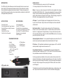
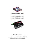
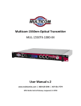
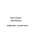
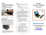
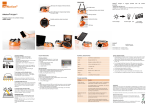
Charging Battery
1. Connect the jack of the AC Adapter (provided) into the slot of the LCD monitor module.
Turn on the power switch.
2. The LED will be RED when the battery begins charging. The LED will change to
GREEN when the battery is fully charged.
Caution:
Don't charge the battery over 8 hours
Don't disassemble Handset or Monitor
Don't use un-approved battery or AC adapter
Don't remove Serial Number Sticker
FIS Fiber Optic
Video Microscope Package
HARDWARE SPECIFICATIONS
Magnification
Field of Vision
Focus
CCD
Monitor
Battery & Power Supply
USB Devices
Dimensions
Video Output
200x by 5.6” LCD, 400x by USB or 9” CRT Monitor
400μm X 300μm
Manual, Maximum 2mm in and out
¼” Sharp CCD sensor
5.6” TFT LCD
9.6V 2700mA NH-AA Rechargeable Battery,
AC adapter for charging by AC 100-220-V
Video Capture Device with Software for Windows 98/2000/XP
Handset (without Tip) 185mm (L) x 24mm (H)
Monitor (when folded) 150 (W) x 125 (D) x 52 (H)mm
NTSC (default) or PAL
WARRANTY
This product was carefully inspected prior to shipping. However, if you should find a defect when you first use this product,
contact us immediately.
The product is warranted for one year, beginning on the date of purchase. During the warranty period, shipping for a
returned product must be prepaid by the customer. FIS will provide repair and replacement for a defective product, according to the terms and conditions of the warranty. The product is expressly NOT COVERED by warranty under the following
conditions:
• Loss or damage caused by an unapproved battery or AC adapter
• The serial number sticker is removed
• Using product under abnormal operating conditions
• Loss or damage due to user fault
• Damage caused by disassembly without permission
F1-VPMKIT200
User Manual
For Tech Support or Service:
Fiber Instrument Sales, Inc.
Phone: 1-800-500-0347
Fax: 315-736-2285
INTRODUCTION
The FIS Fiber Optic Video Microscope is ideal for inspecting fiber optic connector endfaces in the field. The inspection probe makes it easy to inspect connectors, including
those installed within equipment ports and patch panels. The video microscope has a
large 5.6" display screen that makes it easy to spot endface contamination or defects that
can degrade network performance.
APPLICATIONS
KEY FEATURES
• Fiber Optic Systems
• Fiber Sub-Systems within Copper Networks
• Fiber Optic Modules, including Transceivers
• Test Equipment
• Distribution Patch Panels
• Other Fiber Optic Components
• One handed operation
• Wide 5.6” TFT LCD monitor
• Foldable Monitor with adjustable angle
• Easy focusing and charging by AC 100-220-V
• Save Data on PC via optional USB device
• Brightness & contrast adjustable
• RoHS Compliant
STANDARD PACKAGE
• Handset
• 5.6” LCD Monitor
• Rechargeable Battery
• 2 Probe Tips for female
SC/PC - FC/PC and LC/PC
• AC Power Adaptor
• Manual
• Carrying Case
Focus Dial
Tip
LCD module side
• SC Mating Sleeve
• LC Mating Sleeve
• FC Mating Sleeve
PRODUCT SETUP
1. Insert the handset plug into connector on the LCD monitor module
2. You may provide power to the unit in either of two ways:
Battery - To power your video microscope in the field, this unit is supplied with a rechargeable battery (Ni-MH, 2700mA, 9.6V). You may work approximately 4 hours on one battery
charge. You can check battery status by referring to the LED lamp on the LCD monitor
module. When the battery is charged, the LED is green. When recharging is required, the
LED is Red. See charging instructions at the end of this manual.
AC Adapter – To use the AC Adapter, insert the adapter jack into the Power Connector port on the LCD module. Plug the other end of the Adapter cord into a standard AC
electrical outlet.
Dual-Function Switch – The switch located on the side of the LCD module has two
functions. One is to turn the module on and off. The other function, when the switch is
turned on, is to supply power to charge the battery. You may use the microscope under
AC power while the battery is charging. The LED will be GREEN when the unit is receiving
power, either by battery or AC power.
Adjusting Brightness/Contrast – You may adjust the brightness and contrast of the LCD
monitor screen by rotating the adjustment wheel located beside the LCD panel.
PC Interface – 400X magnification available when viewing images on a PC via the USB
module (included). Images can also be saved on a PC.
Using Handset (Probe) Tips – To accommodate different connectors/adapters, this
microscope includes 2 handset tips, SC/PC - FC/PC and LC/PC. Note that the threads on
the tip and handset are similar to facilitate easy tip changes.
Once the appropriate tip is installed, turn the monitor on and insert the probe into the female side of the adapter or other optical component that you wish to inspect. You will feel
when the probe reaches the edge of the adapter. At that time an image should appear on
the monitor. Bring the image into focus by using the FOCUS dial, which can be rotated
over 360 degrees.
The handset has an optical lens that expands the endface image, providing a large, clear
view. Keep the lens clean and be careful not to touch the lens when exchanging tips.