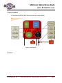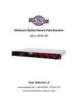
1
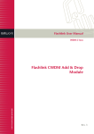
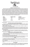
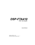
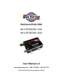
Multicom RFoG ONU MUL‐RFOGONU‐1310 MUL‐RFOGONU‐1610 User Manual v.4 www.multicominc.com | 800‐ 423‐2594 | 407‐331‐7779 1076 Florida Central Parkway, Longwood, FL 32750 Multicom Optical Nano‐Node MUL‐RFOGONU‐xxxx SAFETY NOTIFICATION – IMPORTANT SAFEGUARDS Multicom strongly advises you to read the following safety instructions prior to installing and operating this equipment. Read These Instructions First – All safety and operating instructions should be read before installing or operating this equipment. Retain This Instruction Manual – Safety and operating instructions must be retained for future reference. Ventilation – The Optical Micro‐Node should be kept at a distance from other objects to keep from overheating. Maximum operating ambient temperature is 150°F (65°C). Power Sources – The mains circuit should be a dedicated, unswitched supply. Keeps the unit away from high voltage or other interference creating devices such as motors, compressors, etc. CAUTION: For continued protection against risk of fire, replace circuit breakers/fuses (if necessary) with one of only the same type and rating. Optical Output Safety: Optical Micro‐Node units may emit harmful invisible laser radiation if powered on and the case is opened or the beam path is exposed. The Multicom MUL‐MN‐1000D‐5/42 Optical Micro‐Node is classified as Class 1M per IEC/EN 60825‐1/A2:2001. This product complies with FDA/CDRH, 21 CFR 1040.10 and 1040.11 except for deviations pursuant to Laser Notice No. 50 dated 26 July, 2001. Viewing the laser output with certain optical instruments (for example, eye loupes, magnifiers and microscopes) within a distance of 100 mm may pose an eye hazard. Laser power up to 26 mW at 1310 nm could be accessible if optical connector is open or fiber is broken. Lasers are Powered ON whenever the unit is powered. CAUTION: Use of controls, adjustments, and procedures other than those specified herein may result in hazardous laser radiation exposure. © 2010 Multicom, Inc. www.multicominc.com (800) 423‐2594 | 407‐331‐7779 Page 2 Multicom Optical Nano‐Node MUL‐RFOGONU‐xxxx Table of Contents 1.0 PRODUCT DESCRIPTION 2.0 PRODUCT FEATURES 3.0 BLOCK DIAGRAM 3.1 MUL‐MN‐1000D‐5/42 (Dual fiber bi‐direction, without CWDM) 4.0 EXTERIOR INDICATOR LEDs 5.0 OPERATION NOTICE 6.0 WARRANTY AND REPAIR 7.0 PRODUCT SPECIFICATIONS ……………………………………………………………………………………………………………………………………….. 1.0 PRODUCT DESCRIPTION The Multicom Forward and Return Path RFoG ONU delivers advanced bi‐directional, interactive RF services over a passive fiber optic distribution network. The RFoG ONU serves as the transport layer for RF video, voice, and DOCSIS technologies in deep fiber and FTTH access networks. This not only eliminates the costs of the annual testing and maintenance required to operate the HFC nodes, but also reduces the ongoing power requirements of nodes and RF amplifiers. The RFOG ONU provides services over extended RF frequencies (up to 1.1Ghz), while compatible with both headend and customer premises equipment (CPE), and preserving today’s operating processes. 2.0 PRODUCT FEATURES Complies with SCTE standards and all RFoG network topologies High quality, High performance, Cost effective Available in 1550nm downstream, either 1310nm or 1610nm upstream Small form factor with all electrical and optical connections on side panel 12V positive voltage can be applied to either DC jack or F connector Wide input voltage range from 12V to 18V, with surge protection LEDs indicate power, burst mode and alarm Optimal design for single‐family dwellings and MDU applications © 2010 Multicom, Inc. www.multicominc.com (800) 423‐2594 | 407‐331‐7779 Page 3 Multicom Optical Nano‐Node MUL‐RFOGONU‐xxxx 3.0 BLOCK DIAGRAM 3.1 MUL‐MN‐1000D‐5/42 (Dual fiber bi‐directional, without CWDM) Figure 1 – Block Diagram Familiarize © 2010 Multicom, Inc. www.multicominc.com (800) 423‐2594 | 407‐331‐7779 Page 4 Multicom Optical Nano‐Node MUL‐RFOGONU‐xxxx 4.0 EXTERIOR INDICATOR LEDs Figure 2 – Micro‐Node 1. Power input +12~+15VDC 2. Down‐stream RF output / up‐stream RF input / power input (DC+12V) 3. Power ON LED display 4. Output power test point (1V/mW) 5. Up‐stream RF input level test port (‐20dB) 6. Up‐stream laser output LED display 7. Up‐stream fiber output 8. Down‐stream RF output level test port (‐20dB) 9. Down‐stream fiber input 10. Input power test point (1V/mW) 11. Down‐stream input power LED display 12. Set‐screw grounding location 13. Mounting screw slot © 2010 Multicom, Inc. www.multicominc.com (800) 423‐2594 | 407‐331‐7779 Page 5 Multicom Optical Nano‐Node MUL‐RFOGONU‐xxxx 5.0 OPERATION NOTICE Connect the power supply – Confirm your power supply is between 12‐15VDC and connect to Power Input F‐Connector (1), the Power ON LED will illuminate (3). Do not turn on the transmitter alone or without a protector cover at the unit connector end, otherwise the laser can do harm, especially to eyes. This is especially critical because the laser is not visible to the human eye. Never look directly into the optical port or exposed fiber optic connector without verifying no optical source is present. Always turn off the laser prior to making connections to the transmitter. Failure to do so may cause irreparable damage to the laser and transmitter. Connect the optical input signal: o Inspect and clean the fiber strand optical connector. Using an Optical Power Meter, verify that the optical input signal is between ‐6 and + 3 dBm (0.25 to 2 mW). Alternatively, connect the optical input and measure the DC voltage with respect to ground at the optical input test point (10). The voltage is approximately 1V/mW (between 0.25 and 2.0 V), for proper operation. At this time the LED "Optical Power" will be lit. o Using an RF Signal Meter, measure the RF Downstream Power Level Output (2). The output level should be approximately +25 dBmV per channel with an optical input of 0 dBm (+/‐ 2 dB RF for each 1 dB +/‐ optical input). Alternatively, measure the RF Output at Downstream Level Test Port (8). The level at the test port will be approximately 20 dB below the actual RF output level. o Using an Optical Power Meter, measure the output of the Return Path Upstream Laser connector (7). The output power is a nominal 0 dBm (1 mW). Alternatively, measure the DC Voltage at the Output Power Test Point (4) with respect to ground. The reading should be approximately 1.0 V (1.0V/mW). o Using an RF Signal Meter, verify the RF input to the Micro‐Node is a nominal 20 dBmV. The measurement at RF Upstream Input Test Port (5) will be 20 dB below the actual input level. © 2010 Multicom, Inc. www.multicominc.com (800) 423‐2594 | 407‐331‐7779 Page 6 Multicom Optical Nano‐Node MUL‐RFOGONU‐xxxx Use only Single Mode Fiber (SMF) optic cable (9/125µM). Multi‐Mode Fiber (MMF) is incompatible with the equipment and will result in unacceptable performance and possible damage to the equipment. All fiber splices should be fusion‐type splices. Avoid mechanical or compression type connections. For optimum performance, fiber runs should be made directly from the transmitter to the receiver. Minimize the use of adapters, patch panels, and additional points of failure and signal loss. In order to ensure return loss is maximum, use only SC/APC connectors. Clean and inspect connectors and fiber endfaces prior to installation, and every plug in/out cycle. Use only industry approved methods, materials, and solutions for cleaning. Do not turn on the transmitter alone or without a protector cover at the unit connector end, otherwise the laser can do harm, especially to eyes. This is especially critical because the laser is invisible. Always turn off the laser prior to making connections to the transmitter. Failure to do so may cause irreparable damage to the laser and transmitter. 6.0 WARRANTY AND REPAIR The Multicom MUL‐MN‐1000D‐5/42 has a one year warranty and is subject to Multicom’s standard warrantee terms. There are no user serviceable components inside the unit. The warranty is void if the unit is opened or is damaged due to misuse. © 2010 Multicom, Inc. www.multicominc.com (800) 423‐2594 | 407‐331‐7779 Page 7 Multicom Optical Nano‐Node MUL‐RFOGONU‐xxxx 7.0 PRODUCT SPECIFICATIONS Down‐stream Specifications Operating wavelength (nm) Optical input (dBm) Optical Return loss (dB) Input power test point (V/mW) Connector Max. operating bandwidth (MHz) Flatness (dB) Output return loss (dB) RF Output level (dBmV) Output level test port (dB ref) Impedence (Ω) RF connector CNR (dB) CTB (dB) Link CSO (dB) HUM (dB) Power supply (Volts DC) Power consumption (W) General Operating temp. (ºC) Storage temp. (ºC) Relative humidity (%) Size (WxDxH in mm) Up‐stream Specifications Rev. TX operating wavelength Type of laser with return path Optical Output power (mW) Return loss (dB) Output power test point (V/mW) Connector Operating bandwidth (MHz) Flatness (dB) RF Noise power ratio (dB) Input level (dBmV) Return loss (dB) Input level test port (dB ref) Values 1260 – 1620 ‐6 – +3 >50 1 SC/APC 54 – 1000 ‐0.5 – +0.5 16 25 ‐20 75 F‐female 52 ‐65 ‐60 ‐60 +12 4 ‐20 – 65 ‐40 – 85 5 – 95 130x106x33 Values 1310 FP 1.0 >55 1 SC/APC 5 – 42 ‐0.5 – +0.5 37 20 16 – 18 ‐20 Notes 54~1000 MHz 54~1000 MHz Optical input at 0dB 78 CH, Optical input at 0dBm ‐4 – 150ºF 5¼ x 4¼ x 1¼ inches Notes 5~42MHz FP link loss ≥15dB 5~42MHz © 2010 Multicom, Inc. www.multicominc.com (800) 423‐2594 | 407‐331‐7779 Page 8