1
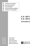
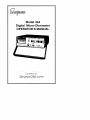
About this Manual
To the best of our knowledge and at the time written, the information contained in this document is technically correct and the procedures accurate
and adequate to operate this instrument in compliance with its original advertised specifications.
Notes and Safety Information
This Operator’s Manual contains warning symbols which alert the user to
check for hazardous conditions. These appear throughout this manual where
applicable, and are defined below. To ensure the safety of operating performance of this instrument, these instructions must be adhered to.
!
Warning, refer to accompanying documents.
Caution, risk of electric shock.
!
This instrument is designed to prevent accidental shock to the operator when
properly used. However, no engineering design can render safe an instrument which is used carelessly. Therefore, this manual must be read carefully
and completely before making any measurements. Failure to follow directions can result in a serious or fatal accident.
Technical Assistance
SIMPSON ELECTRIC COMPANY offers assistance Monday through Friday
7:30 am to 5:00 pm Central Time. To receive assistance contact Technical
Support or Customer Service at (847) 697-2260.
Internet: http://www.simpsonelectric.com
Warranty and Returns
SIMPSON ELECTRIC COMPANY warrants each instrument and other articles
manufactured by it to be free from defects in material and workmanship under normal use and service, its obligation under this warranty being limited to
making good at its factory or other article of equipment which shall within one
(1) year after delivery of such instrument or other article of equipment to the
original purchaser be returned intact to it, or to one of its authorized service
centers, with transportation charges prepaid, and which its examination shall
disclose to its satisfaction to have been thus defective; this warranty being
expressly in lieu of all other warranties expressed or implied and of all other
obligations or liabilities on its part, and SIMPSON ELECTRIC COMPANY neither assumes nor authorizes any other persons to assume for it any other
liability in connection with the sales of its products.
This warranty shall not apply to any instrument or other article of equipment
which shall have been repaired or altered outside the SIMPSON ELECTRIC
COMPANY factory or authorized service centers, nor which has been subject
to misuse, negligence or accident, incorrect wiring by others, or installation
or use not in accord with instructions furnished by the manufacturer.
2
This Instrument is designed to prevent accidental shock to the operator when
properly used. However, no engineering design can render safe an instrument which is used carelessly. Therefore, this manual must be read carefully
and completely before making any measurements. Failure to follow directions can result in serious or fatal accident.
SHOCK HAZARD: As defined in IEC-1010-1 Safety Requirements for Electrical Measurement, Control and Laboratory Use, a shock hazard shall be
considered to exist at any part involving a potential in excess of 30 volts rms
(sine wave) or 42.4 volts DC or peak and where a leakage current from that
part to ground exceeds 0.5 MIU (Measure Indication Units) when measured
with an appropriate measurement instrument as defined in Section 6.3.1.2
Annex A of IEC-1010-1.
NOTE: UL-1244 calls for the same voltage and measurement limits as IEC1010-1:1990 but UL-1244 specifies a slightly different test network. Simpson
Electric manufactures test equipment to measure shock hazard as set forth
by both specifications. The Simpson Model 228 uses the networks specified
by IEC-1010-1 and is suitable for measuring shock hazard as defined in that
document. The Simpson 229-2 uses the measurement networks specified in
UL-1244 and is suitable for measuring shock hazard as defined in that
document.
3
Contents
1. INTRODUCTION ................................................................................ 5
1.1
1.2
1.3
Items And Accessories ....................................................................... 5
Safety Considerations ........................................................................ 5
Technical Data Specifications ............................................................ 5
2. INSTALLATION .................................................................................. 6
2.1
2.2
2.3
2.4
2.5
Unpacking And Inspection ................................................................. 6
Warranty .............................................................................................. 7
Shipping ............................................................................................. 7
Power Source Requirements ............................................................. 7
How to Position Instrument While Operating ...................................... 7
3. CONTROLS, CONNECTORS & INDICATORS ................................... 7
3.1
Front Panel Description ...................................................................... 7
4. OPERATION ...................................................................................... 8
4.1
4.2
Safety Precautions .............................................................................. 9
Operating Instructions ........................................................................ 9
4.2.1
4.2.2
4.2.3
AC Measurement Mode ................................................................... 10
DC Measurement Mode ................................................................... 10
User Settable Continuity .................................................................. 10
5. THEORY OF OPERATION .............................................................. 11
5.1
Theory Of Measurement ................................................................... 11
6. OPERATOR MAINTENANCE .......................................................... 12
6.1
6.2
6.3
6.4
Cover Removal ................................................................................. 13
Battery Replacement ........................................................................ 13
Fuse Replacement ........................................................................... 13
Preventive Maintenance ................................................................... 14
4
1.
INTRODUCTION
The Simpson 444 Micro-Ohmmeter measures resistances from 1 micro-ohm
to 20 ohms. It measures by using a small test voltage (100 microvolt maximum) and a 4 wire measurement technique. The measured resistance is displayed on 4-1/2 digit LCD display. The 444 is designed to be run from the
power line, but self-contained rechargeable Ni-Cad batteries are provided
for field use.
The Simpson 444 has two measurement modes, an automatic AC measurement mode and a manual DC measurement mode. In the AC mode a 100
microvolt maximum square wave is used to test the resistance. Because of
the AC nature of the square wave, all offset voltages and thermocouple effects are automatically canceled and the resistance can be directly read. In
the DC mode, a 100 microvolt maximum DC test voltage is used and the user
must manually cancel out any offsets and thermocouple effects.
1.1
Items And Accessories
All items and accessories required for the operation of the 444 are furnished
with each Instrument, and listed in Table 1-2.
1.2
Safety Considerations
This Operator’s Manual contains cautions and warnings alerting the user to
hazardous operating and servicing conditions. This information is flagged by
CAUTION or WARNING symbols throughout this publication, where applicable, and is defined on the inside front cover of this manual under SAFETY
SYMBOLS. To ensure the safety of operating and servicing personnel and to
retain the operating conditions of this Instrument, please adhere to these instructions.
1.3
Technical Data Specifications
Table 1-1 lists the technical data for the 444 Digital Micro-Ohmmeter.
Table 1-1. Technical Data
The following specifications apply over an operating temperature range of
18° to 28°C and at a relative humidity up to 80% unless otherwise specified.
1.
Accuracy:
2.
3.
Maximum Test Voltage:
Measurement Techniques:
Pulse (AC)
DC
Alarm:
4.
Setpoint Adjustment
AC MODE: ⫾(0.05% of input + 15 counts)
DC MODE: ⫾(0.05% of input + 600 counts)
100µV (Peak)
40 Hertz Square Wave
Switchable Polarity
Resistance below setpoint activates audible
beeper and display annunciator. Resistance
above setpoint activates display annunciator.
Front Panel Knob
5
5.
Accuracy
Hysteresis
Adjustment Range
Display:
6.
Test Leads:
7.
Operating Voltage:
⫾(2% of input + 150 counts)
1% typical
1 to 20,000 counts typical
19,999 count LCD with 0.5" digits and “AC”,
“DC” and “ ” annunciators.
Conversion rate: 2 readings per second
1 meter RG-58 leads with BNC connector one
end and Kelvin clip on the other end.
120 VAC ⫾10%, 240 VAC optional, 3 VA typical
8.
Operating Temperature
Range:
9. Storage Temperature
Range:
10. Relative Humidity:
0° to 50°C
11. Temperature Coefficient:
12. Battery Voltage Effect:
13. Battery Life:
14. Rated Circuit-to-Ground
Voltage:
15. Dimensions:
16. Weight:
–40° to +60°C
90% maximum up to 35°C, 70% maximum up
to +50°C (non-condensing)
0.1 times the applicable accuracy specification per °C (0° to 18°C and 28° to 50°C)
Plus or Minus (0.15% of input). Fully discharged to “B” annunciator displayed.
8 hours typical
30V (rms)
2.7 x 8.4 x 9.0" (68.6 x 213.4 x 228.6 mm)
nominal
Approx. 3 lbs.
Table 1-2. Items and Accessories Furnished With This Instrument
Quantity
1
1
2
Description
Operator’s Manual
Power Cord
Kelvin Test Leads
Part No.
6-114500
5-118916
6-114574
NOTE: Other optional Kelvin type test leads are available from Simpson
Electric.
2.
INSTALLATION
This section contains instructions for the installation and shipping of the 444.
Included are unpacking and inspection procedures, warranty, shipping, power
source requirements, and operation positions.
2.1
Unpacking And Inspection
Examine the shipping carton for damage. If damage is suspected open the
carton and inspect the Instrument for possible damage. If damaged notify the
carrier and supplier before using the Instrument. If the Instrument appears to
be in good condition, read this Operator’s Manual in its entirety. Then run a
series of familiarity tests as instructed in this manual. Also, check that all items
are included with the Instrument (Table 1-2).
6
2.2
Warranty
The Simpson Electric Company warranty policy is printed on the inside cover
of this manual. Read it carefully before requesting a warranty repair.
NOTE: For all assistance, including help with the Instrument under warranty,
read the warranty contained in this manual, then contact the dealer or factory.
You will need date of purchase, the model and serial number of the unit and
a brief description of the problem encountered. Based on the information given,
the customer will be advised how to return the Instrument for service.
2.3
Shipping
Pack the Instrument carefully and ship it prepaid and insured.
2.4
Power Source Requirements
The Simpson 444 is a power line operated Instrument with built-in rechargeable battery backup. The battery automatically charges when the Instrument
is plugged in. The battery may not be charged when the Instrument is shipped.
An 18 hour charging period is recommended before using this Instrument.
2.5
How to Position Instrument While Operating
The Instrument may be operated in a horizontal position or in an inclined
position using the handle as a support.
3.
CONTROLS, CONNECTORS & INDICATORS
Before operating the 444, become familiar with each control. A thorough understanding of how the Instrument operates will avoid undue mistakes and
prolong the life of the Instrument.
3.1
Front Panel Description
Table 3-1 lists all front panel controls, connectors and indicators. (See Figure
3-1 for identification.)
Table 3-1 Front Panel Description
1.
Power Switch:
2.
Range Switches:
3.
Mode Dc/Pulse:
4.
Plus Or Minus:
Push button switch used to apply power to the
Instrument. This switch does not remove power
from the battery charger circuit.
These switches select the maximum resistance
which will yield a full scale reading.
This switch is used to select between the automatic averaging pulse measurement mode and
the manual reading DC measurement mode.
This switch is used in conjunction with the DC
measurement mode to select the test voltage
polarity.
7
Figure 3-1. Front Panel Description
5.
*:
6.
Set:
7.
Level:
8.
Display Area:
Numerical:
Annunciators:
9.
High/Low:
This switch is used to enable the audible continuity alarm.
This switch is used to display the user adjustable resistance level which triggers the audible
continuity alarm.
This control is used to set the resistance level
which triggers the audible continuity alarm. To
display this level, the SET switch must be depressed.
The LCD display area is used to display the resistance measured, the measurement mode,
continuity or lack of continuity and battery condition.
The numerical display is used to indicate the
resistance value of the resistor under test, or the
user setable continuity level.
The up arrow and down arrow indicates whether
the resistance under test is less than or greater
than the setable continuity level.
The “AC/DC” annunciators indicate whether the
current measurement mode is PULSE (AC) OR
DC.
The “B” annunciator appears when the battery
is fully discharged.
These inputs are used to connect the four wire
Kelvin probes to the Instrument. The HIGH/LOW
designation refers to the probe polarity in the +
DC operating mode.
8
4.
OPERATION
This section of the manual contains all the information related to the operation of the Instrument. Special notes and instructions have been included for
added safety.
4.1
Safety Precautions
!
This Instrument is not intended for use on live circuits. Use in circuits exceeding 30V will create a shock hazard which can result in a serious or fatal accident. In addition to being a shock hazard, an energized circuit can damage
the Instrument. Before connecting the Instrument to any component in a circuit, the user must be absolutely certain the circuit is not energized, by disconnecting its power source and discharging any capacitors in the circuit.
1.
2.
3.
4.
5.
6.
7.
8.
9.
The Model 444 Micro-Ohmmeter is intended for use only by personnel
qualified to recognize shock hazards and trained in the safety precautions required to avoid possible injury.
Do not work alone when making measurements where a shock hazard
can exist. Notify another person that you intend to make, such measurements.
Remember, voltages might appear unexpectedly in defective equipment.
An open bleeder resistor can result in a capacitor’s retaining a dangerous charge. Remove all power and discharge all capacitors in the circuit
being measured before making any connections or disconnections. The
above precautions are wise even in the laboratory, and especially in field
usage of the Instrument where many unusual or unknown safety hazards might prevail.
Locate all voltage sources and current accessibility paths prior to making any measurement or connections.
For your own safety, inspect the test leads for cracks, breaks or crazes in
the insulation prods and connectors before each use. If any defects are
noted, replace the defective item(s) immediately.
Do not make measurements near a circuit where corona is present. Corona can be identified by a pale-blue color emanating from sharp metal
points in the circuit, or by a buzzing sound, or by the odor of ozone. In
rare instances, such as around germicidal lamps, ozone might be generated as a normal function. Ordinarily, the presence of ozone indicates
the presence of high voltage, and probably an electrical malfunction.
Hands, shoes, floor and workbench must be dry. Avoid making measurements under humid, damp, or other environmental conditions that could
affect the dielectric withstanding voltage of the test leads or the Instrument.
For maximum safety, do not touch test leads, circuit, or Instrument while
power is applied to the circuit being measured.
Use same test leads as those originally furnished with the Instrument.
9
4.2
Operating Instructions
4.2.1
AC Measurement Mode
The AC measurement mode will provide accurate results on resistances having negligible inductances. To measure resistance using the AC measurement mode:
1. The ALARM SET button and the MODE DC/PULSE buttons must be in
the out position.
2. Select the desired resistance range.
3. Connect the Kelvin probes to the resistance to be tested and turn on the
Instrument.
4. The display will read the resistance directly. If more resolution is desired,
press the range switch which will give the desired resolution.
4.2.2
DC Measurement Mode
The DC measurement mode is used to measure resistances where the inductance is not negligible. Since the automatic noise cancellation circuitry is
disabled, is reading will be less stable. To measure resistance in this mode:
1. Press the MODE DC/PULSE switch in.
2. Select the desired resistance range.
3. Connect the Kelvin probes to the resistance to be tested and turn the
Instrument on.
4. Record the reading shown on the display including the polarity.
5. Press the MODE PLUS OR MINUS switch and record the reading shown
on the display including the polarity.
6. To calculate the measured resistance, subtract the reading makes with
the MODE PLUS OR MINUS switch in the – position from the reading
made with the switch in the + position.
EXAMPLE 1:+ Reading and – reading both positive.
+ reading = 135.6 m⍀
– reading = 83.2 m⍀
135.6 - 83.2 = 52.4 m⍀
EXAMPLE 2:+ Reading positive and – reading negative.
+ reading = 83.2 m⍀
– reading = -52.4 m⍀
To subtract a negative – reading from a positive + reading add the value of
the two readings, i.e.:
83.2 + 52.4 = 135.6 m⍀.
EXAMPLE 3:+ Reading and – reading both negative.
+ reading = -83.2 m⍀
– reading = -135.6 m⍀
To subtract a negative – reading from a negative + reading, subtract the value
of the + reading from the value of the – reading, i.e.:
135.6 - 83.2 = 52.4 m⍀
4.2.3
User Settable Continuity
To set the continuity level:
1. Select the desired resistance range.
10
2.
3.
4.
Connect Kelvin test leads to a resistance within the selectable range.
Depress the ALARM SET switch.
Adjust the level control to the desired continuity level as read on the display.
The audible continuity annunciator is enabled by pressing the ALARM “*”
switch. The alarm will sound when the resistance level drops below the user
settable continuity level.
5.
THEORY OF OPERATION
Conventional resistance measurement is performed by passing a fixed known
current through a resistor and measuring the voltage which results from that
current. This technique is relatively simple and accurate for most resistance
measurements. However, it is less accurate when taking resistance measurements below 20 ohms because of the large currents required to generate the
necessary voltages for full scale readings. Additional problems arise when
the resistance to be measured is sensitive to the heat generated by the measurement current, or when the resistance can be altered by the voltage created by the test current. A different approach must be used to measure low
resistances where such constraints apply.
The Simpson Model 444 is designed to measure resistances down to several
micro-ohms without resorting to high test currents used by other micro-ohmmeters. The Model 444 is designed to test these resistances without applying
more than 100 Micro Volts to the resistance under test. This feature allows the
Model 444 to measure low resistances without the possibility of punch through
or heating in the resistance to be tested. It also makes it possible to use the
Model 444 as a self-contained portable micro-ohmmeter suitable for field use.
5.1
Theory Of Measurement
When using extremely low voltages to measure resistance, several physical
phenomena become significant enough to affect the accuracy of the voltage
readings used to calculate the resistance. These effects are:
1. Voltage drop in the test leads caused by the test current in those leads.
2. Drift and offset in the semiconductor devices used to measure the resistance.
3. Thermocouple effects in wire connections.
Four-wire resistance measurement is a common technique used to eliminate
the voltage drop caused by current in a test lead. This method uses two pairs
of wires to measure resistance. One pair carries the test current while the
other pair is used to transmit the voltage across the resistor back to the ohmmeter. Since no current flows in the voltage measurement leads, no errors
can be introduced in the measurement. The test probes used for this type
measurement are frequently called Kelvin Probes and come in many variations and sizes.
Drift and offset in semiconductors and thermocouple effects are a much more
difficult problem to solve since these effects can contribute to measurement
errors ranging from a few percent to several times the actual resistance. These
11
errors occur when the drift/offset and thermocouple effects appear in the voltage measurement circuit causing the measured voltage to be different than
the actual voltage. While these effects are not constant, they are not affected
by the resistance being tested or by the voltage generated across the resistor
nor do they change quickly. Because of these characteristics, it is possible to
make two measurements and mathematically cancel the errors out.
By measuring the voltage across a resistor with current flowing in one direction we obtain a reading. This reading consists of the errors mentioned in the
last paragraph plus the voltage across the resistor being tested. A second
measurement is then made with the test current reversed. Since the voltmeter
leads were not reversed, this second measurement contains the same errors
as the last measurement but this time the voltage across the resistor has been
subtracted from the measurement. If we take the difference of the two readings we are left with a voltage that is exactly twice the voltage across the
resistor. Ohm’s law can not be used to calculate resistance once the voltage
is divided in half.
The PULSE measurement mode in the Model 444 has automated this method
of testing allowing the user to directly read the resistance without performing
any math. In this mode, the test current provided by the Model 444 is automatically switched from one direction to the other 40 times each second. The
voltage measurement circuit then feeds the resulting voltages created by this
alternating current to a switching network and a sample and hold amplifier
which cancels the errors and provides a corrected resistance reading to the
analog to digital converter. The analog to digital converter turns this reading
to a digital form which is displayed on a liquid crystal display.
Because this method uses an AC test current, it cannot be used to make measurements where inductance is present. For this reason the Model 444 offers
a DC measurement mode. In this mode the current is no longer reversed on a
regular basis. Instead, a constant current is fed to the resistor and a measurement is made that contains the errors. A second reading is taken in which the
test current is shut off and the voltage measurement contains only the errors
generated by the measurement system. To arrive at the correct resistance the
operator must subtract the error reading from the actual reading.
In the DC mode, measurement errors are not canceled 40 times each second. As a result the drift error present in the sources is passed on to the final
reading. This drift will cause the reading to change considerably more than in
the PULSE mode. Simpson Electric suggests that the DC mode not be used
unless absolutely necessary, since the DC mode readings may be less certain.
12
6.
OPERATOR MAINTENANCE
Improper repairs can be dangerous to the operator of the Instrument. Servicing other than as described in this section should be performed only by qualified personnel. Refer to Authorized Service Centers or factory should Instrument require repair or calibration.
6.1
Cover Removal
The bottom cover can be removed for maintenance purposes by the doing
the following:
1. Remove all power and connections to the Instrument before removing
the case cover. Do not operate the Instrument with the bottom cover removed.
2. Set the POWER switch to the OFF position.
3. Disconnect the line cord from the power source and all connections from
the Instrument.
4. Pull out the knobs on the sides of the cover and raise the handle towards
the rear of the Instrument.
5. Turn the Instrument over and remove the four screws within the rubber
feet.
6. Lift bottom cover and remove handle.
7. Reverse this procedure when replacing the cover.
6.2
Battery Replacement
For maximum performance and battery life, use only the proper replacement
Nickel-Cadmium rechargeable battery as supplied with the Instrument. If battery replacement is required, return the Instrument to the factory or the nearest Factory Authorized Service Center.
6.3
Fuse Replacement
The line fuse (F1) and battery fuse (F2) are mounted inside fuse holders on
the main P.C. Board. Use the following procedure to replace a fuse.
1. Remove all power and input connections to the Instrument before removing bottom cover.
2. Remove bottom cover as described in paragraph 6.2.
NOTE: DO NOT replace a blown fuse with a fuse which has a larger rating or
slower time lag characteristic than those specified.
3.
4.
5.
Carefully lift the defective fuse from the holder and replace with an appropriate fuse.
Replace bottom cover.
If the fuse was found to have been blown and replacing it did not restore
operation, circuit damage is indicated. Return the Instrument to the factory or nearest Authorized Factory Service Center for repair.
13
6.4
Preventive Maintenance
!
1.
Do not clean this Instrument with the test leads connected to a power
source or when it is connected to the AC power line.
2. Immediately clean all spilled materials from the Instrument and wipe dry.
If necessary, moisten a cloth with soap and water to clean plastic surfaces.
3. Whenever possible, avoid exposure or usage in areas which are subject
to temperature and humidity extremes, vibration, mechanical shock, dust,
corrosive fumes, or strong electrical or electromagnetic interferences.
4. Verify Instrument calibration by performing operational checks using
known value sources. If the need for calibration is indicated, contact the
nearest Authorized Service Center.
5. When the Instrument is not in use, store it in a location free from temperature extremes, dust and corrosive fumes, and mechanical vibration or
shock.
14
NOTES:
15
SIMPSON ELECTRIC COMPANY 853 Dundee Avenue
Elgin, IL 60120-3090 (847) 697-2260 FAX (847) 697-2272
Printed in U.S.A.
Part No. 06-114500 Edition 6, 02/03
Visit us on the web at: www.simpsonelectric.com
16