1
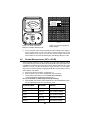
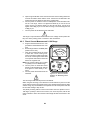
Simpson 260® Series 8P Volt-Ohm-Milliammeters INSTRUCTION MANUAL About this Manual To the best of our knowledge and at the time written, the information contained in this document is technically correct and the procedures accurate and adequate to operate this instrument in compliance with its original advertised specifications. Notes and Safety Information This Operator’s Manual contains warning headings which alert the user to check for hazardous conditions. These appear throughout this manual where applicable, and are defined below. To ensure the safety of operating performance of this instrument, these instructions must be adhered to. ! Warning, refer to accompanying documents. Caution, risk of electric shock. ! This instrument is designed to prevent accidental shock to the operator when properly used. However, no engineering design can render safe an instrument whick is used carelessly. Therefore, this manual must be read carefully and completely before making any measurements. Failure to follow directions can result in serious or fatal accident. Shock Hazard: As defined in American National Standard, C39.5, Safety Requirements for Electrical and Electronic Measuring and Controlling Instrumentation, a shock hazard shall be considered to exist at any part involving a potential in excess of 30 volts RMS (sine wave) or 42.4 volts DC or peak and where a leakage current from that part to ground exceeds 0.5 milliampere, when measured with an appropriate measuring instrument defined in Section 11.6.1 of ANSI C 39.5. Technical Assistance SIMPSON ELECTRIC COMPANY offers assistance Monday through Friday 7:30 am to 5:00 pm Central Time by contacting Technical Support or Customer Service at (847) 697-2260. Internet: http://www.simpsonelectric.com Warranty and Returns SIMPSON ELECTRIC COMPANY warrants each instrument and other articles manufactured by it to be free from defects in material and workmanship under normal use and service, its obligation under this warranty being limited to making good at its factory or other article of equipment which shall within one (1) year after delivery of such instrument or other article of equipment to the original purchaser be returned intact to it, or to one of its authorized service centers, with transportation charges prepaid, and which its examination shall disclose to its satisfaction to have been thus defective; this warranty being expressly in lieu of all other warranties expressed or implied and of all other obligations or liabilities on its part, and SIMPSON ELECTRIC COMPANY neither assumes nor authorizes any other persons to assume for it any other liability in connection with the sales of its products. This warranty shall not apply to any instrument or other article of equipment which shall have been repaired or altered outside the SIMPSON ELECTRIC COMPANY factory or authorized service centers, nor which has been subject to misuse, negligence or accident, incorrect wiring by others, or installation or use not in accord with instructions furnished by the manufacturer. 2 NOTES: 3 Contents 1. INTRODUCTION ............................................................................... 6 1.1 1.2 1.3 1.4 1.5 1.6 1.7 1.8 1.9 1.10 1.11 1.12 1.13 1.14 General Description ........................................................................... 6 Overload Protection ............................................................................ 6 Internal Batteries ................................................................................ 7 Overload Circuit Test .......................................................................... 7 Printed Circuit ..................................................................................... 8 Phenolic Case .................................................................................... 8 Adjust-A-Vue Handle .......................................................................... 8 Test Leads .......................................................................................... 8 Technical Data .................................................................................... 8 Definition of Accuracy ....................................................................... 10 Safety Considerations ...................................................................... 10 Audio Alarm ...................................................................................... 10 Accessory AC High Voltage Probe ................................................... 11 Amp-Clamp Model 150-2 ................................................................. 11 2. INSTALLATION ................................................................................ 11 2.1 2.2 2.3 2.4 2.5 Unpacking and Inspection ............................................................... 11 Warranty ........................................................................................... 11 Shipping ........................................................................................... 12 Power Source Requirements ........................................................... 12 Operating Position ............................................................................ 12 3. CONTROLS, JACKS, AND INDICATORS ........................................ 12 3.1 Front Panel Description .................................................................... 12 4. OPERATION .................................................................................... 14 4.1 4.2 4.3 4.4 4.5 Safety Precautions ........................................................................... 14 Polarity Reversing ............................................................................ 15 Measurement of Unknown Voltage or Current ................................. 15 Test Leads ........................................................................................ 16 DC Voltage Measurement ................................................................ 16 4.5.1 4.5.2 4.5.3 4.5.4 4.5.5 4.6 AC Voltage Measurement 0-2.5 Thru 0-250V Range ........................ 19 AC Voltage Measurement 0-500V Range .......................................... 20 AC Voltage Measurement 0-1000V Range ........................................ 20 Output Voltage Measurement ........................................................... 21 Decibel Measurement (-20 To +50 dB) ............................................ 22 Direct Current Measurement ............................................................ 23 4.9.1 4.9.2 4.9.3 4.10 4.11 4.12 4.13 16 16 17 17 18 AC Voltage Measurement ................................................................. 18 4.6.1 4.6.2 4.6.3 4.7 4.8 4.9 DC Voltage Measurement 0-250 mV Range .................................... DC Voltage Measurement 0-1V Range .............................................. DC Voltage Measurement 0-2.5 Through 0-250V Range ................. DC Voltage Measurement 0-500V Range ......................................... DC Voltage Measurement 0-1000V Range ....................................... Direct Current Measurement 0-50µA Range .................................... 23 Direct Current Measurement 0-1mA Through 0-500mA Range ...... 23 Direct Current Measurement 0-10A Range ...................................... 24 Resistance Measurements ............................................................... 25 Measuring Resistance ..................................................................... 25 Resistance Measurement of Semiconductors ................................. 25 Continuity Tests ................................................................................. 26 5. OPERATOR MAINTENANCE .......................................................... 27 5.1 Inspection ......................................................................................... 27 4 5.2 5.3 5.4 5.5 Battery Replacement ........................................................................ 27 Fuse Replacement ........................................................................... 27 Test Lead Inspection ........................................................................ 28 Care .................................................................................................. 28 5 1. INTRODUCTION 1.1 General Description The Simpson Volt-Ohm-Milliammeter 260 Series 8P, (hereafter referred to as the 260 or as the Instrument) is a rugged, accurate, compact, easy-to-use Instrument equipped with mirrored dial to eliminate parallax. The Instrument can be used to make accurate measurements of AC and DC voltage, direct current, resistance, decibels, and Output Voltage. The Output Voltage function is used for measuring the AC component of a mixture of AC and DC voltage. This occurs primarily in amplifier circuits. New Features in the 260-8P are: 0 - 25V AC/DC Range Continuity Test Alarm Individual Dual Jacks for the 500V AC/DC and 1000V AC/DC Ranges 1.2 Overload Protection All the ranges, with exception of 1V, 10A, 50 µA, 250mV, 500/1000V AC and DC are protected by an electronic overload protection system. The protection is from the usual overloads that would damage the VOM. A transistorized circuit senses the voltage drop across the indicating instrument and actuates a relay when the voltage reaches approximately three to four times rated full scale voltage. Sensing of the voltage drop is by means of a bridge network so that overload protection is provided regardless of polarity. The relay operates at a uniform percent of overload since the indicating instrument circuit is common to all ranges. When actuated by an overload, the relay contacts, which are in the -COMMON CIRCUIT, latch open until the reset button on the front panel is depressed. The reset button is located to the right of the output jack. ! Due to its sensitivity to overloads, the electronic overload protection relay incorporated in the 260-8P is susceptible to electrostatic fields from high potentials or transients either in the circuit being measured or in nearby circuitry. Do not assume the relay to be faulty if it trips out without apparent cause. It may be indicating a dangerous condition such as excessive circuit-to-ground (floating) voltage being applied to the Instrument. Avoid loading the Instrument or its test leads until certain that excessive circuit-toground voltage does not exist. a. A switch that is opened when the relay latches, opens the relay circuit and prevents continuous battery drain. This condition occurs when the reset button has been pressed so that the VOM is operational; the protection circuit draws less than the shelf life drain of the battery. b. Since the 9V battery is used for both the R X 10,000V range and the protection circuit, the VOM is designed to allow the protection circuit to function normally as long as the R X 10,000V range can be set to zero and an Alkaline Battery is used. c. The 1 and 2 Amp fuses in the input circuit adds protection to the relay con- 6 tacts. Some overload conditions may cause the fuses to burn out as well as open the relay contacts. d. When an overload of sufficient magnitude is applied to the VOM, the reset button will “pop-up” approximately 3/16" above the surface of the panel. To reset the VOM for normal operation, first remove the overload and depress the button. If the overload remains connected to the Instrument, resetting the overload protection reset button will not connect the VOM input circuit. In addition to the overload protection circuit, two diodes protect the indicating instrument circuit. These diodes limit the current through the coil in case of overload. Fuses: Basic Overload protection is provided by a small inexpensive and easily obtainable 3 AG type, 1 Amp, quick-blow fuse. This fuse is rated to interrupt circuit voltages up to 250 volts. A supplemental high energy fuse is provided for additional protection from severe overloads. This fuse is the Bussman Type BBS 2A 600V. A Littlefuse Type BLS 2A 600V fuse may be used as a substitute replacement. NOTES: If the 260-8P fails to indicate a reading, the 1 Amp or 2 Amp fuse may be burned out. (Refer to paragraph 5.4 for fuse replacement.) Use only the specified fuse type. The 0-10A range is not fused. The shunt connects directly to the -10A and +10A jacks. The relay, fuse and diodes will prevent serious damage to the Instrument in most cases of accidental overload. However, no overload protection system is completely foolproof and misapplication on high voltage circuits can damage the Instrument. Exercise care and caution to protect both the user and the Instrument. 1.3 Internal Batteries There are two batteries in the ohmmeter circuits, a NEDA 13F size D cell that furnishes 1.5-volts for the R X 1 and R X 100 ranges and a NEDA 1604A alkaline battery that furnishes 9-volts for the R X 10,000 range and overload circuit. The 1.5-volt D cell is held in place with two spring clips which also serve as battery contacts. The polarity symbols for the D cell are marked near the battery contacts. The 9-volt battery is held in place with a spring clip, but contact is made with a separate connector that is polarized. Always observe correct polarity when replacing the 1.5-volt D cell. ! The 9-volt battery must be installed and tested before the Instrument is ready for use. Perform the overload test described in Paragraph 1.4 to ensure proper overload circuit operation prior to using the Instrument. 1.4 Overload Circuit Test a. Set the range switch to R X 10,000 POSITION and the function switch to -DC POSITION. b. Plug the black test lead into the -COMMON jack terminal and touch the other end of the test lead to the +1 volt input terminal. (The relay reset button should rise, indicating that the overload circuit is in working condition.) NOTE: No damage will occur to the 260-8P as a result of this test. 7 1.5 Printed Circuit Most of the component parts are mounted on a printed circuit board which simplifies assembly and maintenance, thus, extending the useful life of the Instrument. 1.6 Phenolic Case The phenolic case is designed with heavy reinforced walls for maximum durability and provides excellent protection for the circuit components. The case has an externally accessible battery and fuse compartment. Access to the batteries and fuses is obtained by unscrewing a single captivated screw at the bottom of the case and sliding out the compartment cover. Rubber plug bumpers on the bottom of the case reduce sliding should the 260 be accidentally pulled by the test leads when the Instrument is on a workbench. 1.7 Adjust-A-Vue Handle A carrying handle is attached to the Instrument case. The handle may be used to support the Instrument in a convenient sloping position for easy viewing. The case can also be placed in either a vertical or horizontal position. The horizontal position is preferable for greater accuracy since the Instrument is calibrated in this position. 1.8 Test Leads Each Instrument is furnished with one pair (Catalog Number 00043) of probe type test leads (one red and one black, each 48 inches long) for all applications of the Instrument. These test leads have elbow prods on one end, to connect the leads to the recessed jacks on the Instrument front panel. The probe tips at the opposite end have threaded shoulders to accept the screw-on insulated alligator clips (furnished with the test leads) or the 5000 volt test probe(s) to extend the Instrument AC or DC voltage range. The test leads and the insulated alligator clips are rated for the voltage and current ranges available on the 260. Maximum ratings are 1000V AC or DC or 10 DC amperes. These ratings for the test leads must not be exceeded in any application. 1.9 Technical Data 1. 2. 3. 4. Table DC VOLTS: Ranges: Sensitivity: DC MILLIVOLTS: Range: Sensitivity: AC VOLTS: Ranges: Sensitivity: OUTPUT VOLTAGE (AC): Ranges: 1-1. Technical Data 0-1-2.5-10-25-50-250-500-1000V 20,000 ohms per volt 0-250mV 20,000 ohms per volt 0-2.5-10-25-50-250-500-1000V 5,000 ohms per volt 0-2.5-10-25-50-250 (limited to 350VDC) 8 5. DC MICROAMPERES: Range: 0-50µA Voltage Drop: 250mV 6. DC MILLIAMPERES: Ranges: 0-1-10-100-500 mA Voltage Drop (Approx.): 250 mV, 255 mV, 300 mV, 500 mV 7. DC AMPERES: Range: 0-10A Voltage Drop (Approx.): 255mV NOTE: The 10A range is not internally fused. 8. RESISTANCE: RX1 R X 100 R X 10,000 Range 0-2,000⍀ 0-200,000⍀ 0-20 M⍀ Center Reading 12⍀ 1200⍀ 120,000⍀ Nominal Open Circuit Voltage 1.5V 1.5V 9V Nominal Shor t Circuit Current 125mA 1.25mA 75µA 9. *ACCURACY: DC Voltage Ranges: DC Current: 0-50 µA Range: Other Ranges: **AC Voltage Ranges: Frequency Response: Resistance Ranges: R X 1: R X 100: R X 10,000: 10. DECIBELS: Range: Reference Level: 11. BATTERIES: Voltage: NEDA No.: 12. FUSE: 13. 14. 15. 16. TEST LEADS: SIZE: WEIGHT: ***RATED-CIRCUIT TO-GROUND VOLTAGE: 2% of Full Scale 1.5% of Full Scale 2% of Full Scale 3% of Full Scale Referenced to 100 Hz (Figures 4-5 and 4-9) 2.5° of Arc 2°of Arc 2° of Arc -20 to +10 dB, -8 to +22 dB, 0 to +30 dB, +6 to +36 dB, +20 to +50 dB With zero dB power level equal to 1 mW across a 600⍀ line. 1.5V, 9V 13F, 1604A F1 1A, 250V, type 3AG, quick-acting Littlefuse Type 312001, F2 2A, 600V Littlefuse Type BLS or 2A 600V, Bussman Type BBS. 1 red, 1 black, 48" long. 5½” x 7" x 3 “ (13.34 x 17.78 x 7.94 cm) 3 lbs. (1.359 kg) 1000V AC/DC Max. 9 *Accuracies specified are for the 260 in a horizontal position. **Responds to the average value of an AC current, and is calibrated to indicate the RMS value of a pure sine wave. ***Per ANSI C39.5 April 1974: “The specified voltage with respect to ground, which may be safely and continuously applied to the circuit of an Instrument.” 1.10 Definition of Accuracy The voltage and current accuracy of this Instrument is commonly expressed as a percent of full scale. This should not be confused with accuracy of reading (indication). For example, +2% of full scale on the 10 volt range allows an error of ±0.20V at any point on the dial. This means that at full scale, the accuracy reading would be ±2%, but at half scale it would be ±4%. Therefore, it is advantageous to select a range which gives an indication as near as possible to full scale. 1.11 Safety Considerations This Operator’s Manual contains special caution and warning symbols which alert the user to hazardous operating and service conditions. These symbols appear throughout this publication where applicable, and are defined on the inside front cover of this manual under NOTES AND SAFETY INFORMATION. Please adhere to these instructions to ensure the safety of operating and servicing personnel and to retain the operating conditions of the Instrument. 1.12 Audio Alarm The 260-8P Audio Alarm is a transducer which will emit an audible sound when the operator of the Instrument intends to quickly determine the continuity of a circuit. NOTE: Not protected by Electronic Overload Protection System. ! Do not make Circuit Continuity Tests with electrical power “ON”. Turn “OFF” all electrical power. Table 1-2. Items and Accessories Furnished with This Instrument Quantity Description 1 Test Lead Set - one red and one black (48” long) each with combination probe tip and removable rubber-sleeved alligator clip. *1 1.5 Volt, D Cell, NEDA 13F *1 9.0 volt Cell, NEDA 1604A 2 1Amp, 250V Fuse, Littlefuse Type #312001 1 2A, 600V Fuse, Littlefuse Type BLS or (Bussman Type BBS) 1 Operator’s Manual Number 00043 6-114339 *Batteries are standard items replaceable from local retail stores. 10 Table 1-3. Additional Accessories Description Deluxe Case Leatherette Ever-Redy Hard Case, Drop Front Model 150-2 Amp-Clamp Model 151-2 Line Splitter 1.13 Catalog No. 00812 00805 00545 00544 Accessory AC High Voltage Probe The 10,000 volts AC accessory probe is similar to the high voltage DC probes with the following exceptions: The AC high voltage probe is designed to extend the 260-8P AC voltage range. The probe can be used with the Simpson 260-8P 10-volt AC range. NOTE: Instructions are furnished with each high voltage probe. 1.14 Amp-Clamp Model 150-2 The Simpson Amp-Clamp Model 150-2 allows AC current measurements without breaking the circuit under test. The Amp-Clamp works as a transformer containing a split core for accommodating the conductor which carries the current being measured. The current-carrying conductor becomes the transformer primary and a coil in the Amp-Clamp serves as the secondary winding. The AmpClamp output voltage is proportional to the current measured and can be applied to the 260-8P as an AC voltage. The Amp-Clamp has a range selector with six positions. Any of the following current ranges can be used with the 260-8P: 5, 10, 25, 50, 100 or 250 amperes. NOTE: Instructions are furnished with each Amp-Clamp. 2. INSTALLATION This section contains information and instructions for the installation and shipping of the Simpson 260-8P. Included are unpacking and inspection procedures, warranty, shipping, power source requirements and operating position. 2.1 Unpacking and Inspection Examine the shipping carton for signs of damage. If damaged, notify the carrier and supplier and do not attempt further use of the Instrument. If Instrument appears to be in good condition, read Operator’s Manual in its entirety. Become familiar with the Instrument as instructed in the manual, then proceed to check the electrical performance as soon as possible. Also, check that all items listed in Table 1-2 are included with the Instrument. After unpacking the Instrument, a 1.5V battery and a 9V battery may be found in separate envelopes in the box with the Instrument and the test leads. Two alligator clips for the test leads are in a polyethylene bag. (See Section 5 for instructions on how to open the battery compartment and install the batteries. 2.2 Warranty The Simpson Electric Company warranty policy is printed on the inside front cover of this manual. Read it carefully before requesting any warranty repairs. For 11 all assistance, including help with the Instrument under warranty, contact the nearest Authorized Service Center for instructions. If necessary, contact the factory directly, give full details of any installation difficulty and include the Instrument model number, series number, and date of purchase. Service data or shipping instructions will be mailed promptly. If an estimate of charges for non-warranty or other service work is required, a maximum charge estimate will be quoted. This charge will not be exceeded without prior approval. 2.3 Shipping Pack the Instrument carefully and ship it prepaid and insured. 2.4 Power Source Requirements There are two batteries in the ohmmeter circuits, a NEDA 13F D size cell that furnishes 1.5 volts for the R X 1 and R X 100 ranges and a NEDA 1604A battery that furnishes 9 volts for the R X 10,000 range. The 1.5 volt D cell is held in place with two spring clips which also serve as battery contacts. The 9-volt battery is held in place with a spring clip but contact is made with a separate connector that is polarized. (Always observe correct polarity when replacing the 1.5-volt D cell.) 2.5 Operating Position A handle is attached to the side of the Instrument case. The handle may be used to support the Instrument in a convenient, sloping position for easy viewing. The VOM case can also be placed either in a vertical or horizontal position. The horizontal position is preferable for greater accuracy since the Instrument is calibrated in this position. 3. CONTROLS, JACKS, AND INDICATORS All operating and adjustment controls, jacks, and indicators for the Simpson 2608P are illustrated in this section along with a list (Table 3-1) describing their function. Become familiar with each item before operating the Instrument. 3.1 Front Panel Description The front panel controls, jacks, and indicators as described in Table 3-1, are depicted in Figure 3-1. Table 3-1. Controls, Jacks, and Indicators 1. Front Panel 2. Range Switch: The 260-8P Volt-Ohm-Milliammeter is a large, easy-to-read 4-1/4” indicating Instrument. Below the Instrument are four controls and eight circuit jacks. Switch positions and circuit jacks are marked in white characters for easy reading. 12 positions: May be rotated 360° in either direction to select any of the five AC and DC voltages, four DC currents and three resistance ranges. 12 O S HM O D.C HM S D.C . A.C . . A.C .C 2.5 V.A D . . B 6 7 1 -10 A. A.C.VOLTS ONLY OUTPUT 350 VDC MAX. +1V. 500 MA. 100MA. 2.5 V. 10MA. 10 V. 1MA. 1V. 25 V. 3 + D.C. 50 A. R X I00 R x I0,000 250 V. - + 500 V. I000 V. 4 Rx1 AMPS. COMMON +10A AMPS. +50250 MV. ZERO OHMS AMPS. - D.C. 260 500 V. 1000 V. A.C. D.C. A.C. D.C. ALL TERMINALS 1 V MAX 5 2 FIGURE 3-1. Front Panel Controls, Jacks and Indicators 3. Function Switch: 4. Zero Ohms: 5. Circuit Jacks: 6. Pointer Adjust For Zero: The function switch has four positions: Audio “*”, +DC, DC, and AC Volts only. To measure DC current or voltage, set the function switch at the -DC or +DC position, depending on the polarity of the signal applied across the test leads. To measure AC voltage set the function switch to the AC position. For resistance measurement, the switch may be set in either the +DC or -DC position. The polarity of the internal ohmmeter battery voltage will be as marked at the jacks when the switch is in the +DC position and reversed in the -DC position. This control is used to compensate for variation in the voltage of the internal batteries, when making resistance measurements. There are eight jacks on the front panel marked with the functions they represent. These jacks provide the electrical connections to the test leads. The COMMON (-) jack is used (in conjunction with the black test lead) as the reference point for the measurement of all the functions with the exception of the 10 A range. (Refer to Section 4 for details.) With the Volt-Ohm-Milliammeter in an operating position, check that the pointer indicates zero at the left end of the scale when there is no input. If pointer is off zero, adjust the screw located in the cover below the center of the dial. Use a small screwdriver to turn the screw slowly clockwise or counterclockwise until the pointer is exactly over the zero mark at the left end of the scale. With the indicating pointer 13 set on the zero mark, reverse the direction of rotation of the zero adjuster slightly to introduce mechanical freedom or “play”, but insufficient to disturb the position of the indicating pointer. This procedure will avoid disturbances to the zero setting by subsequent changes in temperature, humidity, vibration, and other environmental conditions. 7. 4. Reset Button: The white button to the right of the output jack is the reset button of the overload protection circuit. OPERATION ! Multifunction instruments (VOMs) such as the 260-8P are intended as general purpose measuring Instruments for use in low power circuitry such as found in consumer appliances, TV and radio receivers, and in general laboratory applications. Their use is not recommended in high voltage, high power circuitry where operator errors and inadequate personal protective measures could result in serious injury from arcing or explosion. Such circuitry is found in industrial or commercial applications such as induction (r-f) heaters and broadcast transmitters, power substations and distribution centers, X-ray equipment, large motor controls, etc. Working in the high voltage section of such equipment requires single-function, often specially designed instruments used by trained personnel who adopt appropriate protective equipment and procedures. This section of the manual contains information required to use and operate the 260-8P in a safe and proper manner. 4.1 Safety Precautions The following precautions are suggestions and reminders of commonly recognized safe practices to be adopted and specific hazards to be avoided and are not implied to be sufficient to safeguard untrained personnel in all circumstances. Neither is this manual a substitute for technical manuals covering the equipment in which measurements are to be made. Always refer to the equipment manual and its specific warnings and instructions and observe them as well as those contained herein. a. The 260-8P should only be used by personnel qualified to recognize shock hazards and trained in the safety precautions required to avoid possible injury. b. Do not connect any terminal of this Instrument to a circuit point at which a voltage exceeding 1000V AC or DC may exist with respect to earth ground. (Ref. Table 1-1, Item 16.) c. Turn off power and discharge any capacitors in the circuit to be measured before connecting to or disconnecting from it. d. Before using this Instrument, check accessories (if any) and test leads for missing, damaged, deteriorated or otherwise faulty insulating parts. Do not use, or permit the use of equipment with faulty insulation until it has been properly repaired. e. Always wear safety glasses when working with electrical circuitry. 14 f. Do not work alone on high voltage circuits. Make certain that someone capable of giving aid is nearby and alert. g. Do not handle the Instrument, its test leads, or the circuitry while high voltage is being applied. h. Hands, shoes, floor, and workbench must be dry. Avoid making measurements under humid, damp, or other environmental conditions that could effect the dielectric withstanding voltage of the test leads or Instruments. i. Do not change switch settings or test lead connections while the circuit is energized. A mistake could result in damage to the Instrument and personal injury. j. Locate all voltage sources and accessible current paths before making connections to circuitry. High voltages may appear unexpectedly or in unexpected locations in faulty equipment. An open bleeder resistor, for example, may result in a capacitor retaining a dangerous charge. k. Make certain that the equipment being worked upon is properly grounded and fuses are of the proper type and rating. l. Double check switch positions and jack connections before applying power to the Instrument. m. Remain alert for low voltage circuits which may be floating at high voltage with respect to earth ground and for composite voltages (AC + DC) such as are found in r-f amplifiers. The floating voltage or composite voltage must not exceed the Instruments rated maximum circuit-to-ground voltage. n. Do not make electrical measurements where the air may contain explosive concentrations of gas or dust such as in mines, grain elevators, gasoline stations or in the presence of charging batteries until determined to be safe by qualified personnel. Note that even metallic dusts can be explosive. o. No General Purpose VOM is to be used to make electrical measurements on blasting circuits or blasting caps. 4.2 Polarity Reversing The function switch provides a convenient means to reverse polarity of the internal battery to facilitate testing semiconductor devices. The +DC and -DC positions transpose internal connections to the COMMON and +jacks and therefore can also be used to reverse polarity of external voltages and currents connected to these jacks (only). Because polarity reversing momentarily interrupts the circuit, it should not be done while measuring current or voltage without first turning off the circuit power. When making measurements on the 50µA/250mV, 1 volt, or 10 amp range, polarity can be corrected only by reversing the test leads. 4.3 Measurement of Unknown Voltage or Current Sometimes the approximate voltage or current to be measured is known and the correct range may easily be selected. It is often the case, however, particularly when working upon faulty equipment, when the voltage or current is either unknown or may be much higher than normal and anticipated. Whenever working upon unfamiliar or unknown equipment, always begin a measurement using the highest range available on the Instrument. Once it is determined that the voltage is within the limits of a lower range, change to the lower range. 15 4.4 Test Leads Test leads are provided with accessory screw-on alligator clips which may be attached to the probe tips. Eliminating the need to hand-hold test prods to a circuit for extended periods, the test clips also reduce hand proximity to a high voltage circuit while energized. Circuit power must of course be turned off and any charged capacitors discharged before connecting or disconnecting clips to or from the current. 4.5 DC Voltage Measurement ! Before making voltage measurements, review the SAFETY PRECAUTIONS listed in paragraph 4.1. Also, when using the 260 as a millivoltmeter, take care to prevent damage to the indicating instrument from excessive voltage. 4.5.1 DC Voltage Measurement 0-250 mV Range Before using the 250 millivolt range, use the 1.0-volt DC range to determine that the voltage measured is not greater than 250 millivolts (or .25 volt DC). a. b. Set the function switch at +DC (Figure 4-1). Plug the black test lead in the -COMMON jack and the red test lead into the +50µAmps/250mV/10A jack. c. Set the range switch at 50 µAmps (COMMON) position with 50V. d. Connect the black test lead to the negative side of the circuit being measured and the red test lead to the positive side of the circuit. e. Read the voltage on the black scale marked DC and use the figures marked 0-250. Read directly in millivolts. NOTE: For polarity reversing see paragraph 4.2. 4.5.2 DC Voltage Measurement 0-1V Range a. Set the function switch at +DC (Figure 4-1). b. Plug the black test lead into the -COMMON jack and the red test lead into the +1V jack. c. Set the range switch at 1V (COMMON position with 10V). d. Connect the black test lead to the negative side of the circuit being measured and the red test lead to the positive side of the circuit. e. Read the voltage on the black scale marked DC and use the figures marked 0-10. Then divide the reading by 10. NOTE: For polarity reversing see paragraph 4.2. D.C D.C . +1V. D.C. - -D.C. . +10A AMPS. +50250 MV. 10 V. 1V. D.C. ++D.C. 50 A. AMPS. COMMON - + 260 ALL TERMINALS 1 V MAX Figure 4-1. Jacks and Switch Positions for Measuring DC Voltages, 0 through 1V Ranges 16 4.5.3 DC Voltage Measurement 0-2.5 Through 0-250V Range a. Set the function switch at +DC (Figure 4-2). b. Plug the black test lead into the -COMMON jack and the red test lead into the + jack. c. Set the range switch at one of the five voltage range positions marked 2.5V, 10V, 25V, 50V or 250V. NOTE: When in doubt as to the voltage present, always use the highest voltage range as a protection to the Instrument. If the voltage is within a lower range, the switch may be set for the lower range to obtain a more accurate reading. Be sure power is off in the circuit being measured and all capacitors discharged. 260 d. Connect the black test lead to the negative side of the circuit being measured and the red test lead to the positive Figure 4-2. Jacks and Switch side of the circuit. Positions for Measuring DC e. Turn on the power in the circuit being Voltages, 0-250V Range measured. f. Read voltage on the black scale marked DC. For the 2.5V range, use the 0-250 figures and divide by 100. For the 10V, 50V, and 250V ranged, read the figures directly. For the 25V range, use the 0-250 figures and divide by 10. NOTE: Turn off power to the circuit and wait until the meter indicates zero before disconnecting the test leads. D.C D.C . . +10A AMPS. +50250 MV. 2.5 V. - D.C. 10 V. 1V. 25 V. + D.C. 50 A. AMPS. 250 V. COMMON - + 500 V. I000 V. ALL TERMINALS 1 V MAX 4.5.4 DC Voltage Measurement 0-500V Range ! Use extreme care when working with high voltage circuits. Do not touch the Instrument or test leads while power is on in the circuit being measured. Before proceeding with the following steps, review the Safety Precautions in Paragraph 4.1. a. b. c. d. Set the function switch at +DC (Figure 4-3). Set the range switch at the 250V/550V/ 1000V Position. Plug the black test lead into the -COMMON jack and the red test lead into the 500V jack. Be sure power is off in the circuit being measured and all capacitors dis- 17 D.C D.C . . - D.C. + D.C. 250 V. COMMON - 500 V. I000 V. 1000 V. 260 A.C. D.C. ALL TERMINALS 1 V MAX Figure 4-3. Jacks and Switch Positions for Measuring DC Voltages, 0-500V Range charged. Connect the black test lead to the negative side of the circuit being measured and the red test lead to the positive side of the circuit. e. Turn on power in circuit being measured. f. Read the voltage using the 0-50 figures on the black scale marked DC. Multiple the reading by 10. NOTE: Turn off power to the circuit and wait until the meter indicates zero before disconnecting the test leads. 4.5.5 DC Voltage Measurement 0-1000V Range ! Use extreme care when working with high voltage circuits. Do not touch the Instrument or test leads while power is on in the circuit being measured. Before proceeding with the following steps, review the Safety Precautions in Paragraph 4.1. a. Set the function switch at +DC (Figure 4-4). b. Set the range switch at the 250V/500V/ 1000V Position. c. Plug the black test lead into the -COMMON jack and the red test lead into the 1000V jack. d. Be sure power is off in the circuit being measured and all capacitors discharged. Connect the black test lead to the negative side of the circuit being measured and the red test lead to the positive side of the circuit. e. Turn on power in circuit being measured. 260 f. Read the voltage using the 0-10 figures on the black scale marked DC. Multiple the reading by 100. NOTE: Turn off power to the circuit and wait Figure 4-4 Jacks and Switch until the meter indicates zero before Positions for Measuring DC disconnecting the test leads. Voltages, 0-1000V Range D.C D.C . . - D.C. + D.C. 250 V. COMMON 500 V. I000 V. 1000 V. - A.C. D.C. ALL TERMINALS 1 V MAX 4.6 AC Voltage Measurement ! Branch and distribution circuits (120/240/480V etc.) can deliver dangerous explosive power momentarily into a short circuit before the fuse/breaker opens the circuit. Make certain that the Instrument switches are set properly, jacks are connected properly, and that the circuit power is turned off before making connections to such circuits. The 260 responds to the average value of an AC waveform. It is calibrated in terms of the RMS value of a pure sine wave. If the waveform is nonsinusoidal, and 18 depending upon its waveform, the reading may be higher or lower than the true RMS value of the measured voltage. Thus an error may be introduced if the 260 is used to measure a nonsinusoidal waveform. Also, accuracy is lessened at higher input frequencies (Figure 4-5). 4.6.1 AC Voltage Measurement 0-2.5 Thru 0-250V Range PERCENT RELATIVE ERROR Before proceeding with the following steps, review the Safety Precautions in Paragraph 4.1. a. Set the function switch at AC Volts Only position (Figure 4-6). +6 NOTE: The meter will not indicate if AC VOLTAGE RANGES +5 the switch is incorrectly set to a 2.5 VAC RANGE 10VAC RANGE +4 DC position. 25 VAC RANGE 50 VAC RANGE b. Set the range switch at one of the +3 250 VAC RANGE 500 VAC RANGE five voltage range positions +2 1000 VAC RANGE marked 2.5V, 10V, 50V or 250V. +1 (When in doubt as to actual volt0 age present, always use the -1 highest voltage range as a pro-2 tection to the Instrument. If the -3 voltage is within a lower range, the switch may be set for the -4 lower range to obtain a more ac-5 curate reading.) 10Hz 100Hz 1KHz 10KHz 100KHz 1MHz c. Plug the black test lead into the FREQUENCY COMMON jack and the red test Figure 4-5, Frequency Response lead into the + jack. AC Voltage Ranges d. Turn off power to the circuit to be measured and discharge any capacitors. e. Connect the test leads across the circuit voltage to be measured with the black lead to the grounded side. f. For the 2.5V range read the value directly on the scale marked 2.5V AC. For the 10V, 25V, 50V and 250V ranges, read the red scale marked AC and use the black figure immediately above the scale. A.C . . A.C .C 2.5 V.A A.C.VOLTS ONLY . 2.5 V. 10 V. 1V. 25 V. 50 A. AMPS. 250 V. COMMON - + 500 V. I000 V. 260 ALL TERMINALS 1 V MAX Figure 4-6. Jacks and Switch Positions for Measuring AC Voltages, 0-2.5 through 0-250V Ranges 19 Figure 3-1. Fro 4.6.2 AC Voltage Measurement 0-500V Range ! Do not attempt any voltage measurement which may exceed 1000 volts or the circuit-to-ground voltage of the Instrument, 1000 volts maximum. Be sure that the range switch is set to the 250V/500V/1000V range, function switch to AC Volts Only position, and test leads connected to common and 500V jack. Do not touch the Instrument or test leads while the power is on the circuit being measured. Use extreme care when working in high voltage circuits. Do not handle the Instrument or test leads while the circuit being measured is energized. OBSERVE ALL SAFETY PRECAUTIONS in paragraph 4.1 and in the instruction manual for the equipment being tested. Before proceeding with the following steps, review the Safety Precautions in Paragraph 4.2. a. Set the function switch at AC Volts Only position. (Figure 4-7). NOTE: The meter will not indicate if the switch is incorrectly set to a DC position. b. Set the range switch at the 250V/ 500V/1000V position. c. Plug the black test lead into the COMMON jack and the red test lead into the 500V jack. d. Be sure the power is off in the circuit being measured and that all its capacitors have been discharged. e. Connect the test leads across the circuit voltage to be measured with the black lead to the grounded side, if any. f. Turn on the power in the circuit being measured. g. Read the voltage on the red scale marked AC. Use the 0-50 figures and multiply by 10. 4.6.3 A.C . . A.C .C 2.5 A.C.VOLTS ONLY V.A . 2.5 V. 10 V. 1V. 25 V. 50 A. AMPS. 250 V. COMMON 500 V. I000 V. 260 - 500 V. A.C. D.C. ALL TERMINALS 1 V MAX Figure 4-7. Jacks and Switch Positions for Measuring AC Voltage, 0-500V Range AC Voltage Measurement 0-1000V Range ! Use extreme care when working in high voltage circuits. Do not handle the Instrument or test leads while the circuit being measured is energized. OBSERVE ALL SAFETY PRECAUTIONS in paragraph 4.1 and in the instruction manual for the equipment being tested. Do not attempt any voltage measurement which may exceed 1000 volts or the circuit-to-ground voltage of the Instrument, 1000 volts maximum. 20 Be sure that the range switch is set to the 250V/500V/1000V range, function switch to AC position, and test leads connected to common and 1000V jack. Do not touch the Instrument or test leads while the power is on in the circuit being measured. Before proceeding with the following steps, review the Safety Precautions in Paragraph 4.2. a. Set the function switch at AC Volts Only position. (Figure 4-8). NOTE: The meter will not indicate if the switch is incorrectly set to a DC position. b. Set the range switch at the 250V/500V/ 1000V position. c. Plug the black test lead into the -COMMON jack and the red test lead into the 1000V jack. d. Be sure power is off in the circuit being measured and that all its capacitors have been discharged. e. Connect the test leads across the circuit voltage to be measured with the black lead to the grounded side. f. Turn on the power in circuit being measured. g. Read the voltage on the red scale marked AC. Use the 0-10 figures and multiply by 100. 4.7 A.C . . A.C .C 2.5 V.A . A.C.VOLTS ONLY 250 V. COMMON - 500 V. I000 V. 260 1000 V. A.C. D.C. ALL TERMINALS 1 V MAX Figure 4-8. Jacks and Switch Positions for Measuring AC Voltage, 0-1000V Range Output Voltage Measurement Certain situations necessitatethe measuring of the AC component of an Output Voltage where both AC and DC voltage levels exist. This occurs primarily in amplifier circuits. The 260-8P has a 0.1 mfd, 400 volt capacitor in series with the OUTPUT jack. The capacitor blocks the DC component of the current in the test circuit, but allows the AC or desired component to pass on to the indicating instrument circuit. The blocking capacitor may alter the AC response at low frequencies but is usually ignored at audio frequencies (Figure 4-9). Do not connect the OUTPUT jack to a circuit in which the DC voltage component exceeds 350V. Before proceeding with the following steps, review the Safety Precautions in Paragraph 4.1. a. Set the function switch at AC Volts Only position. (Figure 4-10). b. Plug the black test lead into the -COMMON jack and the red test lead into the OUTPUT jack. c. Set the range switch at one of the range positions marked 2.5V, 10V, 25V, 50V, or 250V. d. Connect the test leads across the circuit being measured with the black test lead to the grounded side. 21 +10 OUTPUT RANGES +8 +6 A.C . . A.C .C 2.5 V.A . +4 2.5 VAC RANGE 10VAC RANGE 25/50 VAC RANGE 250 VAC RANGE +2 0 -2 -4 OUTPUT A.C.VOLTS ONLY 350 VDC MAX. -6 500 MA. 2.5 V. -8 10 V. 1V. 25 V. 50 A. -10 AMPS. 250 V. COMMON - 500 V. I000 V. 260 10Hz ALL TERMINALS 1 V MAX 4.8 1KHz 10KHz FREQUENCY 100KHz 1MHz Figure 4-9. Frequency Response Output Ranges Figure 4-10. Jacks and Switch Positions for Output Measurements e. 100Hz Turn on the power in the test circuit. Read the output voltage on the appropriate AC voltage scale. For the 0-2.5V range, read the value directly on the scale marked 2.5V AC. For the 10V, 25V, 50V, or 250V ranges, use the red scale marked AC and read the black figures immediately above the scale. Decibel Measurement (-20 To +50 dB) Some industries measure in terms of voltage or current ratios (decibels) based on a specific reference level. The dB scale on the 260-8P serves this purpose and is calibrated to a reference level (zero dB) or 0.001 watt into 600 ohms. The scale calibration of -20 to +10 dB is for the 0-2.5V range (zero dB = 0.775V). Higher ranges may be used by adding an appropriate dB value to the reading in accordance with the chart below. a. Review the safety precautions in paragraph 4.1. b. Refer to Figure 4-11 for switch settings and jack connections. c. Use operating instructions for AC VOLTAGE MEASUREMENT, 0-2.5/10/25/50/250V RANGES (paragraph 4.6.1). Do not use the 500V or 1000V ranges for decibel readings. d. Read decibels on the bottom scale marked dB. For the 10/25/50/250V ranges, add the appropriate factor from the following chart: VOLTAGE RANGE dB RANGE READING 0-2.5V -20 to +10 read directly 0-10V -8 to +22 add +12 dB to reading 0-25V 0 to 30 add +20 dB to reading 0-50V +6 to +36 add 26 dB to reading 0-250V +20 to +50 add 40 dB to reading 22 NOTE: The maximum voltage ratio that can be measured is +50 dB on the 0-250V range. e. If dB measurements are being made to a 0.006 watt into 500 ohm reference level, subtract +7 dB from the reading obtained on the 260. 4.9 Direct Current Measurement ! a. b. c. d. e. f. 4.9.1 Do not change the range setting of the range or function switches while the circuit is energized. Never disconnect test leads from the circuit under measurement while it is energized. Always turn the power off and discharge all the capacitors before the setting of the switches is changed, or the leads disconnected. Never exceed the circuit-to-ground voltage of the instrument (1000V Max., Table 1-1, Item 16). Always connect the instrument in series with the ground side of the circuit. In all direct current measurements, make certain the power to the circuit being tested has been turned off before connecting and disconnecting test leads or restoring circuit continuity. D B 500 MA. A.C.VOLTS ONLY 2.5 V. 10 V. 1V. 25 V. 50 A. AMPS. 250 V. COMMON - + 500 V. I000 V. 260 ALL TERMINALS 1 V MAX Figure 4-11. Jacks and Switch Positions for Measuring Decibels Direct Current Measurement 0-50µA Range a. b. Set the function switch at +DC. Plug the black test lead into the -COMMON jack and the red test lead into the +50µAMPS/250mV jack. c. Set the range switch at 50µAMPS (dual position with 50V). d. Open the ground side of the circuit in which the current is being measured. Connect the VOM in series with the circuit. Connect the red test lead to the positive side and the black test lead to the negative side. e. Read the current on the black DC scale. Use the 0-50 figures to read directly in microamperes. NOTE: For polarity reversing see paragraph 4.2. 4.9.2 a. b. c. Direct Current Measurement 0-1mA Through 0-500mA Range Set the function switch at +DC (Figure 4-12). Plug the black test lead into the -COMMON jack and the red test lead into the + jack. Set the range switch at one of the four range positions marked 1 mA, 10 mA, 100 mA or 500 mA 23 d. e. f. Open the grounded side of the circuit in which the current is being measured. Connect the VOM in series with the circuit. Connect the red test lead to the positive side and the black test lead to the negative side. Turn the power on. Read the current in milliamperes on the black DC scale. For the 1 mA range, use the 0-10 figures and divide by 10. For the 10 mA range, use the 0-10 figures directly. For the 100 mA range, use the 0-10 figures and multiply by 10. For the 500 mA range, use the 0-50 figures and multiply by 10. Turn the power off and disconnect the test leads. ! This range is only intended for measurements in low voltage circuits (under 25V DC) such as the primary power in vehicles or their accessories. 4.9.3 Direct Current Measurement 0-10A Range a. Plug the black test lead into the -10A jack and the red test lead into the +10A jack. b. Set the range switch at 10 AMPS (dual position with 10 mA). c. Open the grounded side of the circuit in which the current is being measured. Connect the VOM in series with the circuit, connecting the red test lead to the positive side and the black test lead to the negative side. NOTE: The function switch has no effect on polarity for the 10 AMPS range. d. Turn the power on. Read the current directly on the black DC scale. Use the 0-10 figures to read directly in amperes. e. Turn the power off and disconnect the test leads. ! D.C D.C . -10 A. 500 MA. 100MA. . +10A AMPS. +50250 MV. 10MA. AMPS. - D.C. 1MA. + D.C. 50 A. AMPS. COMMON - + 260 ALL TERMINALS 1 V MAX Figure 4-12. Jacks and Switch Positions for Measuring Direct Current The 10A range is not internally fused in the 260-8P. When using the 10A range, never disconnect a test lead from a jack or from the circuit while the circuit is energized. Doing so may damage the test jacks or leads and the arcing may be hazardous to the operator. Turn off circuit power and wait for the meter reading to drop to zero. The polarity reversing feature of the function switch does not operate on the 010A range. If polarity is found to be incorrect, turn off circuit power, wait for the meter indication to reach zero and then interchange test lead connections to the circuit. 24 4.10 Resistance Measurements ! Voltage applied to a resistance range will cause reading errors if low and damage the Instrument if high. When making in-circuit measurements, make certain that the circuit is completely de-energized before making connections to it. When making in-circuit measurements, circuit paths in parallel with the resistance being measured may cause reading errors. Check circuit diagrams for the presence of such components before assuming that the reading obtained is correct. When resistance is measured, the batteries furnish power for the circuit. Since batteries are subject to variation in voltage and internal resistance, the Instrument must be adjusted to zero before measuring a resistance, as follows: a. Turn range switch to desired ohms range. b. Plug the black test lead into the -COMMON jack and the red test lead into the + jack. c. Connect the ends of test leads together to short the VOM resistance circuit. d. Rotate the ZERO OHMS control until pointer indicates zero ohms. If pointer cannot be adjusted to zero, one or both of the batteries must be replaced. (For battery replacement, refer to Section 5.) e. Disconnect shorted test leads. 4.11 Measuring Resistance a. Before measuring resistance in a circuit, make sure the power is off to the circuit being tested and all capacitors are discharged. Disconnect shunting components from the circuit before measuring its resistance. b. Set the range switch to one of the resistance range positions as follows (Figure 4-13): 1. Use R X 1 for resistance readings from 0 to 200⍀. 2. Use R X 100 for resistance readings from 200 to 20,000⍀. 3. Use R X 10,000 for resistance readings above 20,000⍀. c. Set the function switch at either -DC or +DC position: Operation is the same in either position except if there are semiconductors in the circuit. (See paragraph 4.12.) Adjust ZERO OHMS control for each resistance range. d. Observe the reading on the OHMS scale at the top of the dial. NOTE: The OHMS scale reads from right to left for increasing values of resistance. e. To determine the actual resistance value, multiply the reading by the factor at the switch position. (K on the OHMS scale equals one thousand.) 4.12 Resistance Measurement of Semiconductors Make sure that the OHMS range being used will not damage any of the semiconductors (refer to Table 1-1, item 8, Section 1). If there is a “forward” and “backward” resistance such as in diodes, the resistance should be relatively low in one direction (for forward polarity) and higher in the opposite direction. 25 Rotate the function switch between the two DC positions to reverse polarity. This will determine if there is a difference between the resistance in the two directions. To check a semiconductor in or out of a circuit (forward and reverse bias resistance measurements) consider the following before making the measurement: a. The polarity of the internal ohmmeter battery voltage will be as marked at the jacks when the switch is in the +DC position and reversed in the -DC position. b. Ensure that the range selected will not 260 damage the semiconductor. (Refer to Table 1-1, item 8, and review the specification limits of the semiconductor according to the manufacturer’s ratings.) Figure 4-13. Jacks and Switch c. If the semiconductor is a silicon diode Positions for Measuring Resistance or conventional silicon transistor, precautions are not normally required. d. If the semiconductor material is germanium, check the ratings of the device and refer to Table 1-1, item 8. NOTE: The resistance of diodes will measure differently from one resistance range to another on the VOM with the function switch in a given position. For example, a diode which measures 80 ohms on the R X 1 range may measure 300 ohms on the R X 100 range. The difference in values is a result of the diode characteristics and is not indicative of any fault in the VOM. O HM S S HM O ZERO OHMS - D.C. Rx1 + D.C. R X I00 R x I0,000 COMMON + - ALL TERMINALS 1 V MAX 4.13 Continuity Tests ! O HM S S HM O Turn off all power to the circuit under test before proceeding any further. a. Set the FUNCTION switch to the “*”. Insert the black test lead into the COMMON (-) and the red test lead into the (+) jacks, (Figure 4-14). b. Touching the test lead probe tips together should produce an audible sound c. To test for continuity, probe the circuit or component in question. An audible 260 sound indicates continuity. d. The higher the circuit’s resistance, the lower the sound level. The lower the Figure 4-14. Jacks and Switch circuit’s resistance, the higher the Positions for Continuity Tests sound level. e. Refer to Paragraph 4.12, Figure 4-13 for measurements of circuit resistance, if any, that exists. ZERO OHMS - D.C. Rx1 + D.C. R X I00 R x I0,000 COMMON - + ALL TERMINALS 1 V MAX 26 5. OPERATOR MAINTENANCE The following paragraphs of this section describe battery replacement, fuse replacement, and preventive maintenance procedures for the 260. 5.1 Inspection The user is protected from electrical shock by the insulation of the 260 and its test leads. Frequently examine them for any insulation damage such as cracks, cuts, chips, burns or deterioration that expose internal metal parts or reduce the spacing between such metal parts and hand contact by the operator. Make certain that the battery compartment cover is securely fastened in place before the Instrument is used. Do not permit an instrument with a broken meter glass to be used. Whenever the battery compartment cover is removed for any reason, check that the proper fuses are being used. 5.2 Battery Replacement a. Two batteries are used inside the case to supply power for resistance measurements. One is a 1.5-volt D cell and the other is a 9 volt battery. When it is no longer possible to adjust the pointer to zero for the R X 1 and R X 100 ranges (refer to ZERO OHMS ADJUSTMENT paragraph 4.21) replace the 1.5 volt cell. When it is no longer possible to adjust the pointer to zero on the R X 10,000 range, replace the 9 volt battery. b. Recommended replacement batteries are: 1.5V D cell, NEDA 13F (Duracell MN or Eveready No. 95). 9V battery, NEDA 1604A (Duracell MN1604 or Eveready 522). c. To install or replace a battery, de-energize and disconnect test leads from the Instrument, then remove the cover to the externally accessible battery compartment by loosening the single captivated screw. NOTE: Batteries should be replaced before their useful life has expired. Failure to do so may result in corrosion and battery leakage. d. Observe polarity when replacing the 1.5 volt D cell and connect as indicated. The D cell is held in place with spring clips which also act as battery contact clips. The 9 volt battery contacts and connector are polarized. To remove the 9 volt battery, first withdraw battery with mated connector from the compartment. Then remove the connector. 5.3 Fuse Replacement The 1 and 2 ampere fuse (also the 1A spare) is located in the externally accessible battery and fuse compartment. Access to the compartment is obtained by disconnecting the test leads and loosening the single captivated screw on the compartment cover. To replace or check a fuse: Apply pressure to the 1 amp fuse cup then rotate the plate to expose a selected fuse for removal from the panel’s cavity. NOTE: When you replace a fuse, make sure it is the same type and value as the fuse you have just removed. 27 5.4 Test Lead Inspection Periodic inspection of the test leads is recommended to detect cuts, burned areas, deterioration or other damage that could reduce the insulation strength of leads. 5.5 Care a. b. Immediately clean all spilled materials from the Instrument and wipe dry. If the spillage is corrosive, use a suitable cleaner to neutralize the corrosive action. When Instrument is not in use, rotate the function switch to the +DC position. c. Avoid prolonged exposure or usage in areas which are subject to temperature and humidity extremes, vibration or mechanical shock, dust or corrosive fumes, or strong electrical or electromagnetic interferences. d. Verify Instrument accuracy by performing operational checks using known, accurate, stable sources. If proper calibration equipment is not available, contact the nearest Authorized Service Center. If the Instrument has not been used for 30 days, check the batteries for leakage and replace if necessary. e. It is recommended that the Instrument be returned annually to the nearest Authorized Service Center, or to the factory, for an overall check, adjustment, and calibration. f. When the Instrument is not in use, store it in a room free from temperature extremes, dust, corrosive fumes, and mechanical vibration or shock. If storage time is expected to exceed 30 days, remove batteries. Figure 5-1. Battery and Fuse Compartment 28 29 NOTES 30 NOTES 31 SIMPSON ELECTRIC COMPANY 853 Dundee Avenue Elgin, IL 60120-3090 (847) 697-2260 FAX (847) 697-2272 Printed in U.S.A. Part No. 06-114339 Edition 8, 12/01 Visit us on the web at: www.simpsonelectric.com 32