1
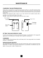
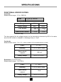
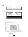
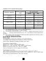
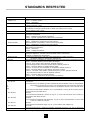
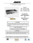
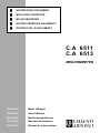
■
CONTRÔLEURS D'ISOLEMENT
■
INSULATION CONTROLER
■
ISOLATIONSPRÜFER
■
CONTROLADORES DE AISLAMIENTO
■
CONTROLLORI DI ISOLAMENTO
C.A 6511
C.A 6513
MEGOHMMETER
FRANCAIS
Mode d'Emploi
ENGLISH
User's Manual
DEUTSCH
Bedienungsanleitung
ITALIANO
Manuale di Istruzione
ESPANOL
Manual de Instrucciones
English
SAFETY PRECAUTIONS
- Before any measurement check that there is no voltage present on the circuit to be tested.
- Use the appropriate leads supplied with the instrument.
- At rest, the needle must indicate 0 on the voltmeter scale. If not, adjust it by means of the
central (6) zero reset screw.
- When the insulation measurement is finished, leave the instrument connected for a few
seconds to allow automatic discharge of the high tension of the device tested.
- During measurement of continuity or resistance, the voltage should be measured first.
The presence of a voltage van activate protection and necessitate changing the fuses.
On the -10W +10W and 1000W ranges, the instrument is protected by an HBC fuse. On the
other ranges the instrument is statically protected on all the ranges from a voltage of
600V rms applied permanently between the terminals and from a voltage of 1000V rms
accidentally applied for less than 15 seconds between the terminals.
- Position the switch in the OFF position when the instrument is not used.
11
SUMMARY
DESCRIPTION
Pages
13
....................................................................................................................................................................
USE .............................................................................................................................................................................................
Battery test ..................................................................................................................................................................
Insulation/voltage measurement .................................................................................................................
Continuity measurement ...................................................................................................................................
Resistance measurement (C.A 6513 only) .........................................................................................
13
13
13
14
14
MAINTENANCE .................................................................................................................................................................
Changing the batteries/fuse ............................................................................................................................
Fitting the shockproof case .............................................................................................................................
Cleaning .........................................................................................................................................................................
Repairs - maintenance .......................................................................................................................................
15
15
15
15
15
SPECIFICATIONS ...........................................................................................................................................................
Functional specifications ...................................................................................................................................
Insulation .......................................................................................................................................................................
Continuity ......................................................................................................................................................................
Resistance (C.A 6513 only) ............................................................................................................................
Voltage ............................................................................................................................................................................
Reference conditions ...........................................................................................................................................
Climatic conditions .................................................................................................................................................
Variations in the nominal working range. ..............................................................................................
Electrical specifications ......................................................................................................................................
Power supply ..............................................................................................................................................................
Electrical safety ........................................................................................................................................................
Mechanical specifications .................................................................................................................................
16
16
16
16
16
17
17
17
18
18
18
19
19
STANDARDS RESPECTED
....................................................................................................................................
20
...........................................................................................................................................................................
21
.........................................................................................................................................................................
21
TO ORDER
WARRANTY
12
DESCRIPTION
See page 54 and page 55.
➀ - Measurement terminals colour marked
➁ - Log scale on yellow background 0.1 to 1000 MW : Insulation measurement.
➂ - Linear scale 0 to 10 W : Continuity measurement
Resistance measurement (C.A 6513 only)
➃ - Linear scale 0 to 600 V AC : Voltage measurement
➄ - Red / green scale : battery test
➅ - Screw to reset needle to mechanical zero
➆ - Rotary switch : 4 positions (C.A 6511)
6 positions (C.A 6513)
➇ - Press button
USE
BATTERY TEST
Before starting a series of measurements, check that the batteries powering the instrument
are good. Place the switch in the OFF position, press the yellow button, and display the
condition of the batteries on the
scale of the galvanometer :
- if the needle is in the green zone, the batteries are good
- if the needle is in the red zone, change the four batteries
INSULATION/VOLTAGE MEASUREMENT
Once you are sure the power supply is good (see "Battery test"), you can proceed with
insulation measurements.
Connect the instrument to the installation to be tested using the accessories supplied (leads
and crocodile clip). It is preferable that the "+" is connected to the earth. Select an insulation
measurement position with the switch (500 V for the C.A 6511, 500 or 1000 V for the C.A
6513).
At this stage, the instrument is thus automatically set to AC voltmeter. The instrument
makes a voltage measurement between the + and - terminals (scale of voltages up to 600 V AC).
- If the instrument does not indicate any voltage present, the insulation measurement can be
made.
- If the instrument indicates the presence of voltage on the circuit to be measured, insulation
measurement must not be made. Find the source of this voltage and suppress it. Insulation
measurements can only be done on this condition.
Proceed with the insulation measurement, by pressing the yellow button. The instrument
generates a high voltage between the + and - terminals. The reading is done on the yellow
log scale 0.1 to 1000 MW . As soon as the button is released, the instrument switches to
voltage measurement. The high tension present on the tested device is discharged via the
leads of the instrument. You must therefore leave the instrument connected for a few
seconds once the measurement is finished 13
(needle returns to 0 V).
CONTINUITY MEASUREMENT
After having connected the instrument to the installation to be tested, you must check that no
voltage is present (see "Insulation measurement/voltage").
Set the switch to the "10 W " position.
The measurement is done automatically without having to press the yellow button. Read the
value on the white scale 0 to 10 W . Then set the switch to the "-10 W " position and check that
the needle of the instrument indicates the same continuity value. If this second value is
different from the preceding one you must make the following calculation :
Rcontinuity = R+10 W + R-10 W
2
To have a better measurement accuracy on the +10 W and -10 W ranges, measure the
resistance of the leads by short-circuiting them. Then subtract this value from the measured
resistances.
Remarks : - In order to save battery power, it is preferable to disconnect the leads once
the continuity measurement has been finished.
- If the instrument, on continuity measurement, is not connected, or is badly
connected, the needle then positions itself to the far right.
RESISTANCE MEASUREMENT (C.A 6513 only)
After having connected the instrument to the installation to be tested, you must check that no
voltage is present (see "Insulation measurement/voltage").
Set the switch to the "1000 W " position.
The measurement is done automatically without the need to press the yellow button.
Read the value on the white scale 0 to 10 W , applying a coefficient x100.
Remarks : - If the instrument, on resistance measurement, is not connected, or is badly
connected, the needle then positions itself to the far right.
- In order to save battery power, it is preferable to disconnect the leads once
the resistance measurement is finished.
14
MAINTENANCE
CHANGING THE BATTERIES/FUSE
Check that no terminals are connected and that the switch is in the OFF position before
opening the instrument. For safety, the instrument can only be opened if the leads are
disconnected from the terminals. Access to the fuses and the batteries is by opening the back
of the case.
Remove the shockproof case if there is one, then undo the tool release screws with a
screwdriver and remove the back of the case.
Warning : never press the yellow button when the case is open.
Tool release
screws
Fuse 1.6 A
Fold away
stand
+
+ +
-
- -
4 batteries
1.5 V LR6
+
-
FITTING THE SHOCKPROOF CASE
In order not to damage the window protecting the display, it is preferable to first engage the
upper part of the instrument in the case, then to push the lower part in.
CLEANING
Clean the case of the instrument with a soft damp cloth. Use soapy water but not alcohol,
solvents or hydrocarbons.
REPAIRS-MAINTENANCE
The maintenance operations must be done with original parts, and by an approved service
department. To obtain a good quality measurement, it is preferable to recalibrate every two
years, or every year in case of intensive use.
15
SPECIFICATIONS
FUNCTIONAL SPECIFICATIONS
Insulation
Measurement range : 0.1 to 1000 MW
Scale
0,1 MW to 1000 MW
Accuracy
± 5% of the measurement
Range
500 V
1000V*
Empty voltage
600V
1200V
Test current
³ 1 mA for
R £ 500 kW
³ 1 mA for
R £ 1 MW
Short circuit current
£ 6 mA
£ 6 mA
* C.A 6513 only
The time required for the voltage present on the terminals to decrease by 90% of its value,
once the MW button is released (= discharge time), is 1s/µF.
Continuity
Measurement range : 0 to 10 W with reversal of the measurement current
Scale
0 - 10 W
Accuracy
± 3% of end of scale
Short circuit
current
³ 200 mA
Empty voltage
4.5 V £ V £ 6.5 V
Resistance (C.A 6513 only)
Measurement range : 0 to 1000 W
Scale
0 - 1000 W
Accuracy
± 3% of end of scale
Short circuit
current
³ 2mA
Empty voltage
4.5 V £ V £ 6.5 V
16
Voltage
Measurement range : 0 to 600 V AC
Scale
0 - 600 V
Accuracy
Input impedance
± 3% of end of scale
300 kW
Reference conditions
Distortion quantities
Temperature
Reference conditions
20 °C ± 3K
Relative humidity
Supply voltage
45 to 55 % RH
5.5 V ± 0.2 V
Voltage frequency
Electric field
45 Hz to 65 Hz
< 1 V/m
Magnetic field
Position
< 40 A/m
Horizontale ± 5°
Climatic conditions
Humidity in % RH without condensation
Temperature
in °C
Nominal reference range
Working range
Storage range
17
Variations in the nominal working range.
% variation of
the measurement
Limits of working
range
Typical
Operating
position
0 + 90 °
0 - 90 °
-
£ 5 % of
the measurement
Temperature
-10 to + 55 °C
3 % / 10°C (1)
5 % / 10°C (1)
Humidity
20 to 80 % RH (2)
5 % of
the measurement
10 % of
the measurement
Supply voltage
4.5 to 6.5 V
0.1 % of
the measurement
0.2 % of
the measurement
Frequency (on voltmeter)
45 to 400 Hz
-
£ 0.1 % of
the measurement
Electromagnetic field
0 to 400 A/m (3)
-
1/2 class
Distortion quantities
Max.
(1)
For measurements in MW , it is a % of the measurement.
For the other measurements, it is end of scale.
(2) For insulation measurements from 0.1 to 100 MW , voltage measurements from 0 to
continuity measurements from 0 to ± 10 W and resistance measurements from 0
600 V,
to 1000 W .
(3) The magnetic fields envisaged are fields with stable amplitude and direction, and of
frequency between 0 and 60Hz.
ELECTRICAL SPECIFICATIONS
Power supply
The instrument is powered by 4 batteries 1.5V type R6 alkaline
The voltage range ensuring correct operation is from 4.5V to 6.5V
Check correct operation by testing the battery (see "Use").
Consumption is approximately :
300mA for R = 0.5 MW on the MW 500V range
600mA for R = 1 MW on the MW 1000V range (C.A 6513 only)
200mA on continuity on the +10 W and -10 W ranges
10mA on ohmmeter on the 1kW range (C.A 6513 only)
The average service life is :
1000 insulation measurements of 10s on the MW 500 V range for R = 500 kW ,
200 insulation measurements of 10s on the MW 1000 V range for R = 1 MW (C.A 6513 only)
1500 continuity measurements of 10s on the 10 range.
18
Electrical safety
Dual insulation instrument in accordance with standard IEC 1010-1, for a set live-earth
voltage of 600 V, installation category III, and degree of pollution 2.
Reminders of definitions :
- Installation category : classification of installations in accordance with standardised limits
for
transient access voltages depending on the nominal voltage of the network in
relation
to
ground.
- Degree of pollution : classification of micro-environments. See IEC 1010.
- Set voltage : nominal voltage in relation to the earth.
MECHANICAL SPECIFICATIONS
Dimensions : 167 x 106 x 55mm
Weight : 500g approx/650g with sheath (batteries included)
19
STANDARDS RESPECTED
Standards
VDE 0413-1
VDE 0413-4
VDE 0100
NFC 15100
IEC 1010-1
NFC 42 100
NF EN 50 081-1
NF EN 50 082-1
NF EN 60 555
NF EN 55 014
NF EN 55 022
IEC 801
Publication 160
NF EN 60 529
IEC 68.2.6
on
the
100).
IEC 68.2.27
IEC 68.2.29
at
IEC 68.2.31
IEC 68.2.32
case
UL 94
Titles
VDE specifications for testing protective devices in electrical installations.
Part 1 : insulation testers
Part 4 : ohmmeters
Specifications for the creation of high current installations of nominal
voltage less than 1000V.
Design, production, checking and maintenance of electrical installations
powered by a voltage at most equal to 1000V (rms value) on AC current
and at 1500V on DC current.
Safety rules for electronic instruments
Electrical measurement instruments analogue direct movement panel meters
and their accessories.
Part 1 : Definitions and general regulations
Part 7 : Special regulations for multi-function instruments.
Electromagnetic compatibility. Generic emission standard.
Part 1 : Residential, commercial and light industry.
Electromagnetic compatibility. Generic immunity standard.
Part 1 : Residential, commercial and light industry.
Disturbances produced in power supply networks by electrical domestic equipment
and analogous equipment.
Part 2 : Harmonics
Part 3 : Voltage fluctuations
Limits and measurement methods for the specifications of electric
domestic appliances, portable tools and similar electric instruments,
relating to radioelectric disturbances.
Limits and measurement methods of the specifications of data processing
equipment relating to radioelectric disturbances.
Electromagnetic compatibility for measurement and control equipment in industrial processes.
Part 2 : Sections relating to electrostatic discharges
Level 3 : 8 kV close to the instrument, aptitude criteria B.
The instrument holds 15 kV with contact with an aptitude criteria A.
Part 3 : Sections relating to radiated electric fields
Level 2 : 3 V/m from 27 to 500 MHz not modulated, aptitude criteria A
Part 4 : Sections relating to rapid electric transients in salvos
Level 2 : 1kV peak, wave 5/50ns, repetition frequency 5 kHz, aptitude criteria B.
The instrument holds 4 kV with an aptitude criteria A.
Part 5 : Sections relating to electric shocks
Level 3 : 2 kV. (not defined in NF EN 55 082-1 at present)
Normal atmospheric conditions for tests and measurements
Degrees of protection obtained by the case.
Fundamental climatic tests and mechanical sturdiness
Vibrations
The instrument in its operating position withstands vertical vibrations of 0.15 mm amplitude
the frequency range from 10 to 55 Hz. The sweep speed is one octave per minute and
duration of the test is 30 min (in accordance with IEC 1010-1 and NF C 42The instrument withstands vibrations of ± 1 mm amplitude (i.e 2.5 g) at 25 Hz and for 20 min
(in accordance with VDE 0413).
Shocks
The instrument withstands 3 shocks of 15 g for 11 ms in both directions on the 3 axes (in
accordance with NFC 42-100).
Shakes
The instrument withstands 1000 shakes of 10 g for 16 ms in both directions on the 3 axes
a rate of 1 shake per second.
Bumps
The instrument withstands drops of 5 cm. (in accordance with VDE 0413).
Free fall
The instrument which is hand-hold portable, withstands free fall of 1 m with or without the
(in accordance with IEC 1010-1)
Self-extinguishing capability.
20
TO ORDER
C.A 6511 Megohmmeter .......................................................................................................................... P01.140201
supplied with 1 set of leads, 1 red crocodile clip, 1 spare fuse
and 1 User manual
C.A 6513 Megohmmeter .......................................................................................................................... P01.140301
supplied with 1 set of leads, 1 red crocodile clip, 1 spare fuse
and 1 User manual
Spares :
Shockproof case ............................................................................................................................................... P01.298016
Leads 181A/181B ............................................................................................................................................ P03.100819
Red crocodile clip ............................................................................................................................................. P01.101803
Fuse 6.3 x 32 1.6A HBC ............................................................................................................................. P01.297022
Set of 4 batteries 1.5 V LR6 ..................................................................................................................... P01.100759
Accessory :
Black crocodile clip
.........................................................................................................................................P01.1018.02
WARRANTY
Unless dispensation to the contrary, our instruments are guaranteed from any manufacturing
defect or matérial defect.
They do not bear the specification known as the safety specification. Our guarantee, which
may not under any circumstances exceed the amount of the invoiced price, goes no further
than the repair of our faulty equipment, carriage paid to our workshops. It is applicable for
normal use of our instruments, and does not apply to damage or destruction caused, notably
by error in mounting, mechanical accident, faulty maintenance, defective use, overload or
excess voltage, calibration performed by third parties.
Our responsability being strictly limited to the pure and simple replacement of the faulty parts
of our equipment, the buyer expressly renounces any attempt to find ue responsible for
damages or losses caused directly or indirectly.
Our guarantee is applicable for twelve (12) months after the date on which the equipment is
made available. The repair, modification or remplacement of a part during the guarantee
period will not result in this guarantee being extended.
21