1
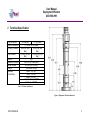
Unit 17 Denmore Industrial Estate, Denmore Road, Bridge of Don, AB23 8JW User Manual Deployment Window 205-1588-HH1 OPS-1588 REV B User Manual Deployment Window 205-1588-HH1 Revision History Issue, Date Rev A Rev B, 3 Oct 11 OPS-1588 REV B Remarks Initial Issue T-Seals now H85 Material and ORings now V90 Material i User Manual Deployment Window 205-1588-HH1 Revision History ............................................................................................... i Safety ............................................................................................................. iii 1 Introduction .............................................................................................. 1 1.1 Product Identification ............................................................................ 1 2 Technical Specification ............................................................................ 3 3 Technical Description .............................................................................. 4 3.1 Basic Set Up ........................................................................................ 4 4 Operation ................................................................................................. 5 4.1 Opening the window............................................................................. 5 4.2 Closing the window .............................................................................. 5 4.3 Removing the lubricator ....................................................................... 5 4.4 Attaching the lubricator ........................................................................ 6 4.5 Job Planning ........................................................................................ 6 5 Maintenance ............................................................................................ 8 5.1 Introduction .......................................................................................... 8 5.2 Schedule .............................................................................................. 8 5.3 Safety................................................................................................... 9 5.4 Tools .................................................................................................... 9 5.5 Redress Procedure .............................................................................. 9 5.6 Maintenance Record Sheet ................................................................ 12 6 Testing .................................................................................................. 13 7 Parts List and Drawings ......................................................................... 14 8 Spares ................................................................................................... 16 Table 1: Technical Specification ..................................................................... 3 Table 2: Maintenance Record ....................................................................... 12 Table 3: Parts List ......................................................................................... 14 Table 4: Redress kit Part No RDK-1588-HH1 ............................................... 16 Figure 1: Deployment Window Safety ............................................................. iii Figure 2: Deployment Window Dimensional ................................................... 3 Figure 3:Operational Set Up ........................................................................... 4 Figure 4: Assembly ....................................................................................... 15 OPS-1588 REV B ii User Manual Deployment Window 205-1588-HH1 Safety WARNING: Trapped air requires considerable time to compress and when it is compressed is highly dangerous. It has enough stored energy to separate parts with considerable force. All pressure equipment has a particular pressure rating and care must be taken to ensure that no item is used in a situation that may cause its working pressure to be exceeded. All personnel involved in pressure testing must be formally trained, competent and utilise the appropriate PPE. Ensure the identification plate is fitted and is displaying the correct information as per the Tag Sheet/Index This equipment and the equipment it is attached to is heavy never position yourself below a suspended load Finger and clothing trap areas Figure 1: Deployment Window Safety OPS-1588 REV B iii User Manual Deployment Window 205-1588-HH1 1 Introduction The Deployment Window is used directly above the Deployment BOP to provide a safe working environment for making or breaking the upper section of the wire-line tools during the deployment operation, while the lower section is held in the BOP. The use of the window allows the operator direct access to the string connections that would otherwise require a special latching and delatching operation. In addition the window allows the use of industry standard wire-line connections on the string and so allows existing equipment to be utilised. The Deployment Window consists of a sleeve that can be pumped open to allow access to the work string and pumped closed to seal off the well environment. Snap rings act on the piston to prevent accidental movement due to pressure build up in the hydraulic lines, such that more than 500 psi (800 psi typical) is required before the piston will move. When the piston releases from the snap ring a click can be clearly heard and provides a clear indication that the sleeve is moving. When fully opened a safety pin can be withdrawn from a storage location and inserted into the lock position. This provides a physical barrier to the downward movement of the sleeve acting as a safety device for those working within the window. There is sufficient space in the window to use spanners and tools to make and break the wire-line string. There is no need to back up on the low string connection as the BOP pipe rams hold that securely. When the sleeve is closed two sets of seals are energised and a test port allows pressure to be applied between the seals thus verifying the seal integrity of the window without the need to fill the whole lubricator string. The upper section of the Deployment window interfaces with the pressure control lubricator stack and is configured with an industry standard union thread to suit the required working pressure. Breaking the window top cap and lifting disconnects the lubricator stack. When made up again, later in the operation, and after the top cap is made up, pressure can be applied between the two seals to verify the sealing integrity – once again without the need to fill the lubricator string. This user manual serves as an introduction to the equipment and contains the relevant specifications, operation, planning and maintenance instructions, parts list and drawings. 1.1 Product Identification Phuel products are identified by a unique serial number that facilitates full product traceability. Each product is supplied with a documentation pack that OPS-2017 Rev B 1 User Manual Deployment Window 205-1588-HH1 contains product certification and material/inspection reports. The serial number is always etched on the surface of the product but can sometimes be difficult to find or read after painting. A customer identification number is also included to allow the customer to track the asset in their system. A stainless steel band secures the nameplate tag that is stamped with the information shown below. This tag should be located in the first instance to ensure that this manual refers to the correct equipment. P H U E L O IL T O O L S L T D D E S C R IP T IO N & S IZ E C U S T O M E R ID N o P H U E L ID N o 06 -X X X -X X M W P & S E R V IC E TEST D A TE OPS-2017 Rev B 2 User Manual Deployment Window 205-1588-HH1 2 Technical Specification Top Connection Bottom Connection Working Pressure Test Pressure Service Hydraulic Pressure Stroke Volume Weight Hydraulic Connections 9.5-4 ACME 11.5-4 ACME 7-1/16 BX 10K FLANGE 6,500 PSI (448 10,000 PSI (690 Bar) Bar) 10,000 PSI (690 15,000 PSI (1035 Bar) Bar) H2S 3,000 PSI (210 Bar) MAX 46.3 cu-in (0.76 litres) 1665 LBS (756 Kg) Open - 1/2" NPT Close - 1/2" NPT Bleed - 1/2" NPT Lubricator Test - 1/2" NPT Seal Test - 1/2" NPT Table 1: Technical Specification Figure 2: Deployment Window Dimensional OPS-1588 REV B 3 User Manual Deployment Window 205-1588-HH1 3 Technical Description 3.1 Basic Set Up The deployment window is essentially a pressure vessel with a sliding sleeve that can be pumped open or closed. When closed, the seals isolate the opening in the outer housing from pressure. When open, the sleeve is fully retracted to allow physical access into the lubricator bore for the purpose of making and breaking tool string connections. To reduce the time for deployment operations the window has a fast test feature at the sleeve so that the seals can be tested with a hand pump prior to filling the lubricator. A similar test feature has been incorporated at the top so that when the lubricator section is assembled the seals can be tested with minimal effort. Finally a bleed port is provided to allow the lubricator to be drained prior to opening the window. The diagram below shows a typical operational arrangement. The pumps used are not part of the system and so their operation is out with the scope of this manual. Refer to the specific equipment manuals for operation details if required. It is important to realise that when opening and closing the window that the low-pressure fluid must be exhausted, preferably back to the reservoir. Figure 3: Operational Set Up OPS-1588 REV B 4 User Manual Deployment Window 205-1588-HH1 4 Operation 4.1 Opening the window Verify that the well pressure has been bled off. Ensure that all the seal test valves are open to bleed. Switch valve on pump pack to open position. Switch on pump slowly. Observe pressure gauge to see pressure rise sharply and then fall to pumping pressure. Continue to pump until window is fully open and pressure starts to rise. Stop Pump and bleed off the pressure. Set valve to isolated position. Withdraw the safety pin from the storage location and insert into the lock position. Secure with the clip. Operation Complete. 4.2 Closing the window Ensure that all the seal test valves are open to bleed. Verify that the lower seals are in good condition and that there is no significant build up of sand or well debris around the seals and snap ring. Clean up if required. Withdraw the safety pin from the lock position and insert into the storage location. Switch valve on pump pack to closed position. Switch on pump slowly. Observe pressure gauge to see pressure rise sharply to 800 psi approx and then fall to pumping pressure. Continue to pump until window is fully closed and pressure starts to rise. Stop Pump and bleed off the pressure. Set valve to isolated position. Close the seal test bleed valves and slowly apply pressure to the test pressure. (Bleed off several times to remove the air to achieve a good test if necessary). After a good test bleed off the pressure and close the needle valve. Operation complete. 4.3 Removing the lubricator Ensure that all the lubricator test valves are open to bleed. OPS-1588 REV B 5 User Manual Deployment Window 205-1588-HH1 Unscrew the Collar (item 4) until the threads are completely disengaged. Use a 3/8 Hex key in the socket head cap screws (item 20) for leverage if required. Lift the lubricator up with the crane, pulling slowly until the Test Sub (Item 3) clears the top of the window. Check the condition of the o-rings and prepare to change if required. Operation Complete. 4.4 Attaching the lubricator Ensure that all the lubricator test valves are open to bleed. Lower the lubricator with Test Sub (Item 3) into the top of the window. Inspect the condition of the o-rings and apply grease before stabbing in. Lift the Top Cap (Item 4) while stabbing in. Make up the Collar (item 4) taking care not to damage the threads. Fully make up using a 3/8 Hex key in the socket head cap screws (item 20) for leverage if required. Close the lubricator test bleed valves and slowly apply pressure to the test pressure (Bleed off several times to remove the air to achieve a good test if necessary). After a good test bleed off the pressure and close the needle valve. 4.5 Job Planning 4.5.1 Pre Job Ensure that the assembly is in good condition and that the certification is within date and that the scheduled maintenance is up to date. It is recommended that the test port o-rings are replaced before every job and T-seals are replaced every 200 cycles. Check the equipment history and if in doubt replace the seals. Only replace the body connection o-rings when the T-Seals are being redressed. Pressure test window to 1.2 x maximum expected well pressure. Function test the window to ensure that the operation is as expected. 4.5.2 During the Job Use the Safety Pin to lock the window in the open position at all times while working through the window. Store the pin in the storage hole when not in use and always secure with R-Pin. When the window has been opened, clean the area around the seals and lower snap ring. Remove any excessive sand or debris that could prevent the snap ring from functioning. Apply grease to the seals if required. Inspect lower seals and replace if there are signs of damage or if the pressure testing has failed. OPS-1588 REV B 6 User Manual Deployment Window 205-1588-HH1 Hydraulic Hose ends should never be allowed to drop in to dirt or grit, or otherwise become contaminated with foreign matter. Any dirt or grit introduced into the may lead to serious damage to the equipment. If hoses become dirty, they should be cleaned thoroughly with solvent and dried. Only clean Hydraulic fluid should be used (Shell Tellus 22 is recommended) to operate the Window. The use of mixed types, dirty, or very old fluid of unknown origin is not recommended. When one of these conditions is known or suspected, the hydraulic system should be flushed with solvent and the hydraulic fluid replaced. 4.5.3 Post Job Move the window approximately to the ¾ open position Clean the area around the bottom of the sleeve and inspect the seal areas. Report any scratched or damage so that it be addressed before the next job Clean the area around the seals and lower snap ring. Remove any excessive sand or debris that could prevent the snap ring from functioning Coat the sleeve, seals and snap ring in grease Close the window fully Clean and then grease the area of the sleeve that is exposed at the window Fit protection caps to any free end connections to. Stow equipment in container and secure for transport OPS-1588 REV B 7 User Manual Deployment Window 205-1588-HH1 5 Maintenance 5.1 Introduction Regular maintenance of the equipment using Phuel redress kits or Phuel approved parts is essential to its continued safe operation. Ensure that the pre and post job operating procedures are followed and that maintenance records are kept. 5.2 Schedule The maintenance schedule may be governed by international or company standards and the following is considered to be the minimum requirements. 5.2.1 Pre & Post Job Refer to Section 4.5.1 and Section 4.5.3 for details. Note that it is not necessary to replace the body connection seals after every job as a metal sealing connection protects these elastomers. It is recommended that the two T-Seals accessible through the open window (Item 13 be replaced after they have been exposed to H2S or CO2 environments) 5.2.2 Yearly Disassemble window (see section below) clean and degrease all components Inspect the condition of all sealing surfaces and surface coatings Re-coat threads and sealing surfaces if necessary. Contact Phuel if in doubt Replace all elastomeric seals (See Section Error! Reference source not found.) Re-assemble per section below Pressure Test to maximum working pressure and 300 psig per API 6A – PSL3 (Witnessed by certifying authority where applicable) Inspect paint work and repair where necessary 5.2.3 Five Yearly Yearly maintenance plus the following Carry out surface NDE on all component threads and damaged surfaces Pressure Test to maximum test pressure and 300 psig per API 6A – PSL3 (Witnessed by certifying authority where applicable) OPS-1588 REV B 8 User Manual Deployment Window 205-1588-HH1 5.3 Safety Many of the components are heavy and should not be lifted without lifting aids Wear appropriate personal protective equipment Do not over exert yourself while using torque wrenches. Use appropriate mechanical advantages when available. Ensure that all tools and equipment are in good condition and are suitable for the intended use. 5.4 Tools The following tools are required. Memac Chain Wrench (No 3 with 14” chain). Pipe wrenches may be used but will mark equipment 3/8 hex Allen key Hydraulic pump to operate window (during dis-assembly) Sledge hammer & aluminium block Hydraulic pump and gauge for pressure testing 5.5 Redress Procedure 5.5.1 Dis-Assembly Ensure that the window is fully closed Remove the chains for the Safety Pin (12) and R-Pin and lay to one side Remove the Collar (4) and then remove the Fast Test sub (3). This is easier when in the vertical orientation as a suitable lift cap may be used to remove the sub. No further dis-assembly of this sub is required unless there are obvious signs of damage or if more access to the threads are required for NDE investigations. To strip down further remove the four screws (20) and unscrew the split ring halves (5) while maintaining a constant gap between the split with a suitable screw driver or plate. Hold the Window assembly in the vice, gripping over the box connection on the bottom sub (6). Break and remove the Top Sub (2) Lift out the upper snap ring (10) Connect the hydraulic pump to the open port and pump to open the window. With the Top Sub removed the Piston Sleeve (1) will pump out of the bore at which point the pumped fluid will flow from the end of the window, use a bucket to collect the spilled fluid. Stop pumping at this point. Take the weight of the Piston Sleeve on the crane and remove it, again OPS-1588 REV B 9 User Manual Deployment Window 205-1588-HH1 collecting spilled fluid in a suitably positioned container. Disconnect the pump. Break and remove the Housing (7) and lay down Remove the Bottom Sub (16) from the vice only if it is necessary to complete the next step. Note that the position of centre of gravity for the part makes it difficult to sling. It is recommended that a suitable shackle be used in the flange holes for safe lifting. Grip the Housing (7) in the vice taking care not to crush test ports Unscrew the Ring Sub (11) and the remove the Lower Snap Ring (9). Remove all Test Ports (8) from the Housing (2 off), Top Sub (2 off) and Bottom Sub (1 off) by removing the two Hex socket screws (19) and pulling against the o-ring friction. It is best to leave the fittings attached to the NPT port until after the Ports have been removed as this provides extra leverage at this stage. Remove all O-rings and seals from the parts and discard. Inspect sealing surfaces for scratches, pit marks, bending, cracking or damage . Ensure that only competent personnel carry out the inspection of components. Replace or repair any components as required. 5.5.2 Re-Assembly Ensure that elastomeric seals are not damaged or excessively stretched during assembly. Use new seals from the appropriate Phuel redress kit and check that the dates are within a useable period. Lightly grease all threads and sealing surfaces Place up the Lower Snap Ring (9) inside the Housing (7) taking care that the orientation matches that shown by the drawing (Shallow angle closest to the window opening). Make up the Ring Sub (11) hand tight. (There is no need to use a vice for this) Locate the Bottom Sub (6) in the vice gripping over the box connection. Take care not to crush the box section Fit the o-rings (16) to the Housing (7) end connections and then make it up the threaded connection with the window opening closest to the Bottom Sub (6). Tighten using the wrench until the test port sockets between the two parts are closely aligned. Fit the T-Seals (13) inside the Housing ensuring that the splits in the back ups are approximately 180° apart and are overlapping correctly. Coat lightly with grease Fit the T-Seal (14) to the Piston Sleeve (1) ensuring that the splits in the back ups are approximately 180° apart and are overlapping correctly. Coat lightly with grease. OPS-1588 REV B 10 User Manual Deployment Window 205-1588-HH1 Lift the Piston Sleeve and insert into the Housing taking care to maintain the centralisation when the leading end of the sleeve passes through the seals. When the sleeve reaches the housing seals place the aluminium block across the protruding end face of the sleeve and drive into the bore using sharp blows with a hammer. Several blows will be required to drive the sleeve to the almost fully closed position (There is no need to engage with the Lower Snap Ring!). Take care while swinging the hammer and be aware of other personnel in the working area. Fit the Upper Snap Ring (10)taking care that the orientation matches that shown by the drawing (Shallow angle facing you). Fit the T-Seal (13) inside the Top Sub (2) ensuring that the splits in the back ups are approximately 180° apart and are overlapping correctly. Coat lightly with grease. Apply grease to the protruding end of the Piton Sleeve (1) and make up the Top Sub(12) to the Housing and tighten using the wrench until the test ports are closely aligned Fit each of the Test Ports (8) to the Housing (2 off), Top Sub (2 off) and Bottom Sub (1 off) by fitting the o-ring (13) and pushing into the seal bore. Secure with the two screws (19). The fitting of the Fast Test Sub (3) and Collar (4) may not be required (consult operational requirements) at this stage and may be replaced with a lift/test cap. If it is to be fitted then remove the assembly from the vice and stand vertically on the flanged face. (Consider fitting the protector plate to the flange to avoid damage.) If the Test Collar (4) and Split Ring (5) have been dis-assembled then reassemble it by screwing the split segments in from the end of the collar with the drilled holes. Make up fully and then back off until the holes line up (Flange face should be flush to sub-flush with the collar). Insert the four screws (20) with lock washers (21) hand tight first and then tighten with 3/8 Allen Key. Note that this assembly may need to be done on the Fast Test Sub (3) if the top connection is larger than the bore through the assembled split ring Fit the two o-rings (17 & 18) to bottom of the Fast Test Sub (3) and then lift the sub using the appropriate lift cap and stab into the top of the Top Sub (2). Knock down if required. Make up the Collar (4), using a 3/8 Allen key in the cap screws for leverage if required. OPS-1588 REV B 11 User Manual Deployment Window 205-1588-HH1 5.6 Maintenance Record Sheet Date Type of Performed Performed Maintenance By Verified By Comments Table 2: Maintenance Record OPS-1588 REV B 12 User Manual Deployment Window 205-1588-HH1 6 Testing All testing is to be carried out in the designated test area and by suitably qualified and competent personnel. WARNING: Trapped air requires considerable time to compress and when it is compressed is highly dangerous. It has enough stored energy to separate parts with considerable force. Fit appropriate test caps and blanking plugs Fill with testing fluid bleeding off any air within the system Apply a pressure of 500 psi and ensure pressure holds for a minimum of 10 minutes Increase pressure to 10,000 psi (Maximum Working Pressure), allow to stabilise, maintain this pressure until it is evident there are no apparent leaks. .(Testing to be carried out to Test pressure when decreed by maintenance schedule) Bleed off pressure, drain test fluid and dry Remove test caps Apply coating of de-watering solution to protect the bore and threads Fit thread protectors On completion of all maintenance ensure the maintenance record sheet (Para 5.6) is completed OPS-1588 REV B 13 User Manual Deployment Window 205-1588-HH1 7 Parts List and Drawings Item Number 1 2 3 4 5 6 7 8 9 10 11 12 13 14 15 16 17 18 19 20 21 Part Number 205-1589-480 205-1590-480 205-1728-480 205-1592-480 205-1593-480 205-1595-480 205-1594-480 900-1631-480 205-1596-480 205-1657-480 205-1606-480 205-1670-174 802-1634-H85 802-1633-H85 801-0119-V90 801-0375-V90 801-0448-V90 801-0449-V90 SHC-0582-B7M SHC-0586-HTS WNL-0580-STL Quantity 1 1 1 1 1 1 1 4 1 1 1 1 4 1 5 2 1 1 10 4 4 Description Piston Sleeve Top Sub FAST TEST SUB COLLAR (SPLIT TYPE) SPLIT RING BOTTOM SUB HOUSING TEST PORT SNAP RING UPPER SNAP RING RING SUB SAFETY PIN T-SEAL ROD 8.25 X 8.75 X 0.366 T-SEAL PISTON 8.5 X 8 X 0.366 O-Ring - B.S Size 119 O-Ring - B.S Size 375 O-Ring - B.S Size 448 O-Ring - B.S Size 449 Soc Hd Cap Size 1/2 Length 0.625in Soc Hd Cap Size 1/2 Length 1.25 in Nord Lock Washer (M12) Table 3: Parts List OPS-1588 REV B 14 User Manual Deployment Window 205-1588-HH1 Figure 4: Assembly OPS-1588 REV B 15 User Manual Deployment Window 205-1588-HH1 8 Spares Use only spares supplied or approved by Phuel Oil Tools Ltd. It is recommended that sufficient quantities of the following spares be maintained to ensure that the equipment is always available when required. Part Number 802-1634-H85 802-1633-H85 801-0119-V90 801-0375-V90 801-0448-V90 801-0449-V90 Quantity Description 4 1 5 2 1 1 Comments T-SEAL ROD 8.25 X 8.75 X 0.366 T-SEAL PISTON 8.5 X 8 X 0.366 O-Ring - B.S Size 119 O-Ring - B.S Size 375 O-Ring - B.S Size 448 O-Ring - B.S Size 449 Table 4: Redress kit Part No RDK-1588-HH1 8.1.1 Individual Items Individual items may be ordered as required using the part number specified Note: O-Rings conform to industry standards and may be substituted with those from other suppliers -– at the sole risk of the user. OPS-1588 REV B 16