1
Turbidostat Hardware and Software Design
MS 4
By:
Peter Harker
Maxwell Holloway
Evan Dreveskracht
Table of Contents
1. Introduction………………………………………….... 3
2. Hardware
2.1 Scanner Assembly Design………………….….. 3
2.2 Circuit Boards………………………………..... 4
2.3 Gripping Mechanism………………………….. 7
3. System Model Discritized…………………………….. 8
4. Software Implementation
4.1 Arduino Software……………………………… 10
4.2 PI Controller Software………………………… 12
5. Conclusions…………………………………………….13
6. Appendix A……………………………………………. 14
7. Appendix B……………………………………………. 17
2
1. INTRODUCTION
For the fourth milestone we are focusing on the main components of our hardware and
software design, and discussing our choices for each. These designs are the must
fundamental aspects of this project, and give an overview of our project as a whole. Our
hardware includes the scanner housing, circuit boards, and liquid handler. This week and
part of next we will be focusing on completion of the scanner housing and circuit board
specifically, which will be determined on shipping times and CNC mill availability. For
the software of our system we will explain the Arduino and PI controller code. Further
incorporating the PI controller code with the liquid handler is also needed, but will be
incorporated after our system and readings are working properly.
2. HARDWARE
The turbidostat design project consists mainly of hardware design and programming the
hardware to do what we want it to do. There are two main categories for which the
hardware is made up of, that is the plastic housing unit, and the printed circuit boards
containing the surface mounted LED’s and photodiodes. To design and make these have
consumed a considerable amount of time, but when finished we will have a fully
functional plate scanner ready to read optical densities in a 24 big well plate.
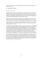
2.1 SCANNER ASSEMBLY DESIGN
Figure 1: Scanner assembly where printed circuit boards (top and bottom) and plate (center) will sit
3
This is currently the design we hope to use for our plate scanner. We have been running
into some issues financially in getting it made with the budget we have. In order to
achieve the best quality paying someone to mill it on a CNC is far too expensive which
caught us by surprise. The other option is to rapid prototype, or use a 3D printer, but our
customer has concerns about the precision of the printer and there is also that same price
issue in getting it made that way. The likely solution that we came up with will be to use
the CNC located in the SOS lab on the third floor of the electrical engineering building.
Figure 2: Drawings for scanner housing
These are the drawings that make up the assembly. It is easy to see that there are a lot of
little details in the design of all three of the major parts. The difficulty that was run into in
designing this was that after all was done on paper, going out and getting an estimate on
actually making it deemed to be rather troublesome due to the functionality of the CNC
dealing with the square corners and 45 degree chamfer on the inside wall. Some revision
had to be done before getting an accurate estimate. As simple as the design already
stands, trying to make it simpler would exclude some of the key features that are needed
in our plate scanner to get it to run efficiently. Right now were considering a more
economical and rapid fabrication just to begin refining the turbidostat and all its various
functions.
4
2.2 CIRCUIT BOARDS
In order to make measurements of the optical density of the individual wells, two
different circuit boards are being created: one board for the 24 photodiodes and one board
for the 24 LEDs.
Photodiode Circuit Board
Figure 3 Dimensional Picture of Photodiode Board
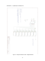
The photodiode circuit board will be screwed into the lid of our enclosure using standoffs and predrilled holes in both the board and the lid. Figures a1 and a2 in Appendix A
show the components that will be used in both of these boards. Figure a2 shows a higher
level representation with 3 shift registers that will take in serial data and will send out
parallel controls to for each “block.” Each of these “blocks” consist of eight photodiodes
that all use the same control lines. The A0, A1, and A2 control signals sent into the
blocks are used to control a 3 to 8 decoder that selects the output enable lines of one of
each of the photodiodes, so that one of these are being read at one time. The S0, S1, S2,
and S3 control lines control the sensitivity and frequency scaling of the photodiodes.
Controls S0 and S1 are used to control the sensitivity using the following table:
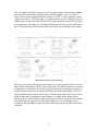
Figure 4 - Effects of S0 and S1 on the Photodiode
Controls S2 and S3 control the frequency according to the following table:
5
Figure 5 - Effects of S2 and S3 on the Photodiode
The following list shows the components that are used for the photodiode circuit board:
- (3) Shift Registers – 74LS595
- (1) Buffer – 74LS541
- (3) 3 to 8 Decoders – 74LS138
- (24) Photodiodes (Light to Frequency Converters) – TSL230
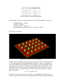
LED Array Circuit Board
Figure 6: Dimensional Picture of the LED Board
The LED array circuit board will be screwed into the bottom “plate” of the enclosure that
we created using stand-offs and predrilled holes in both parts. Figure a3 in appendix A
shows the schematic for the LED board. In this schematic, you can see that there are two
integrated circuits (ICs) that are connected to the grounds of the 24 LEDs. These ICs are
current drivers that are used to provide a constant current that is the same for all of the
lights. This current is referenced using an external resistor on pin 23 and also using the
following equation:
IOUT,target = (1.25 V/Rext) × 15
We want 20.1 mA and are using a 931 Ω resistor to accomplish this. We had to use two
different current driver ICs because the maximum amount of LEDs that can be hooked up
6
to one of these components is 16 and we need to hook up 24. In order to set up our
circuit correctly, we daisy chained two of the ICs so that both drivers can be controlled
through on serial output. The basic way that one of these drivers works, is by taking in
serial data on pin 2, a clock on pin 3 that clocks the data input, a latch signal on pin 4 that
sets the current data set up to the outputs, and an output enable on pin 23. How this is
connected to the Arduino board will be addressed with more specifics in the next section.
The following list shows the components that are used for the photodiode circuit board:
- (2) Current Drivers - TLC5926
- (24) LEDs – HLMP-EJ10-XZ0DD-ND (Digikey Part Number)
- (2) 0.1 µF Capacitors (For Noise Control)
2.3 GRIPPING MECHANISM
Figure 7: Use of gripper to pick up plate and re-locate it
One of the solutions to facilitating this design project was to use make use of the gripper.
This is one of the functions of the liquid handler located in the SOS lab. Using this
enables us to place and remove the lid (as shown in figure 1) without the use of a servo
motor. This is important since our turbidostat will have to perform two main functions
every 15 minutes, which are take readings (lid on) and extract and refill wells (lid off).
Another function which will be performed once a day will be the exchanging of plates
which lies inside the housing unit. The gripper will also be utilized in that way.
In order to accomplish this there will be lots of calibrating involved to ensure that the
gripper picks up and drops off in exactly the right position. There are options in the liquid
handler software which allows you to step to a gripping position and save the position to
memory.
7
3. SYSTEM MODEL DISCRITIZED
In our last couple reports we showed what our controller would do in a continuous
control setting. In reality our system acts more discretely then continuous since our
sample time is once every 15 minutes. This means that although bacterial growth is
continuous, our controller assumes one value of optical density every 15 minutes. It does
not take into account that the bacteria population is still growing. What we want to see is
how close our system model is to a real life setting and if our controller is good enough.
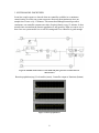
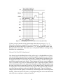
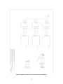
Figure 8: Simulink model with zero order holds and pulse generator to achieve discrete
characteristics
Bacteria population (top), Fresh media (center), Controller output or Nutrients (bottom)
Figure 9: Desired population 0
8
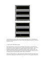
Figure 10: Desired population 0.7
Figure 11: Desired population 1.2
In discretizing our system to take into account the large sample time, we found that our
proportional and integral gains were a little to high. By adjusting these gains we achieved
reasonable results.
4. SOFTWARE IMPLIMENTATION
The implementation of software for our turbidostat will be done on 3 separate devices
and will entail 3 separate programs with 3 separate programming languages. The issue we
struggled with was how to interface all of these together in order to achieve a fully
functional turbidostat without any significant time delay or data acquisition errors. The
obvious solution to that predicament was to allow for each program to write to a text file
so that the program requesting data would be able to read in the file.
The devices and programs we will be using are the Arduino mega which provides its own
programming language, the liquid handler which provides its own program and language,
9
and the PC which will carry out the liquid handler software and our PI controller code
written in java or C.
4.1 ARDUINO SOFTWARE
The Present “Test” Code
The following is a description of the code that we currently have set up on our Arduino
Mega board. This is by no means a finalized version of the code that we have, and will
certainly be changed by the final product. What we have so far is the basic code that is
needed to test the readings of the photodiode which are taken in, the LEDs turning on and
off as needed, and the drawing of the correct amount of current.
Appendix B shows the code that is currently on our Arduino Mega. This code utilizes
many of the registers used on the Atmel ATmega1280 microcontroller to set up various
interrupts, timers, counters, and more. We decided that working more low level with the
microcontroller instead of using the Arduino development code would be more desirable
because it would give us access to the interfaces of the microcontroller, and would give
us more control over our code.
The code that is shown in appendix B utilizes an external counter on pin 47 (TCNT5) that
counts the low to high transitions on the incoming digital signal. This pin is hooked up to
the output of the photodiode and is counted until the interrupt service routine (ISR) is
fired as defined in the upper portion of the code. This ISR is set up to fire when Timer 4
reaches a certain value (which was calculated to be 8000 in order for the interrupt to fire
approximately every second). When this interrupt fires, the counter value (which
corresponds to the frequency of the signal, since it is printed every second) is printed to
the serial console. Additionally, we can accept user input from the console to turn LEDs
on and off through the current driver (which will be explained more in-depth below). We
have connected one current driver IC (with eight LED outputs, we are using a slightly
different Texas Instrument that drives only 8 LEDs instead of 16; however, the concept is
the same) to the microcontroller using an SPI interface. This interface allows serial input
to be taken in by the current driver in the form of 8 bits which then select which LEDs
should be on and off. As shown by figure 5:
10
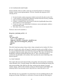
Figure 12 - Timing Diagram for Current Driver Test Chip (TLC5916)
We have set up an interface in the serial monitor where the user can type ‘o’ or ‘f’
followed by a number to turn an LED on or off, respectively. For example, if “o1” is
typed into the console, then LED 1 is turned on. If “f1” is typed into the console, then
that same LED is turned off. This allows us to verify that the LEDs are working as they
should use the current drivers.
Planned Code That Will Be Implemented
Now that we have the building blocks of the code set up (i.e. the photodiodes are being
read and the LEDs are being turned on and off through the current driver), we will have
to use these building blocks to create our final code. Portions that are left that are yet to
be implemented are the 3 to 8 decoder, the second current driver, and the shift registers
used for the control signals to the blocks. These changes will be very easy to implement.
The 3 to 8 decoder is very easy to control and only needs 3 input lines (a binary value) to
select which output will be a low signal while the others are high. The shift registers use
the same concept as the current drivers and we will be running USART interfaces as SPI
to control these. The second current driver only requires that we hook up the serial data
out of the first current driver to the serial data in of the second. Then we will have to
change our SPI function slightly to send the first 8 bits through to the second chip before
latching. When our final circuit comes, we will begin testing the code on our final board
and verify that everything is working as should be.
11
4.2 PI CONTROLLER SOFTWARE
The PI controller software will be written in java and will perform our closed loop
feedback control system implementation. The basic functions this program will be
carrying out are:
1. Execute the plate scanner program on Arduino and read in the data saved to file.
2. Create an array of current optical densities read in from text file sent by Arduino.
3. Send each OD through the PI control loop.
4. Perform a calculation from OD to units in which the liquid handler knows how
much solution to extract and replace.
5. Create two arrays, one with amount of solution to extract and another with how
much nutrients to add.
6. Write these values to two separate files.
The basic code of a PI controller is:
integrator_state[num_wells] := 0
while 1
for each well W
error := read_well(W)-ref
integrator_state[W] := integrator_state[W]+error
u[W] := kp*error+ki*integrator_state[W]
output(u)
wait
The while loop keeps going as long as there is data coming from the Arduino file. Since
there are 24 wells, num_wells will equal 24. Inside the loop the read_well[W]-ref gives
the error calculated and will be used when the respective proportional and integral gains
are applied to find the needed output u[w] of the controller. This value will then be sent
through the calculation and inserted into the array of values. After this program is
executed, the liquid handler will read those files to perform the actual controlling of the
bacterial growth.
5.0 CONCLUSIONS
The work for this project has been divided up irregularly with each member contributing
when difficulties arise. Generally though, Peter Harker has been building the housing unit
and system modeling, Max Holloway has been working on the arduino set up and
software design, with Evan Dreveskracht working on interfacing the liquid handler, and
soldering. Much of our meetings involve help from our various advisors as well.
This milestone was very important as it sets the stage to test our modeling behavior and
design specifications. Difficulties we still need to overcome include the following list:
12
-
The drilling out of the housing unit to desired size.
Soldering and incorporating circuits with housing unit
Arduino to PI controller to Liquid handler communication
3 to 8 decoder, second current driver, and shift registers used for the control
signals to the block code set up for the microcontroller
Testing to determine any further problems
This next week will be very important in completing and implementing our design for
testing, and also determine what flaws we need to overcome.
13
APPENDIX A – HARDWARE SCHEMATICS
Figure a1 - Components Inside Each "Box" of Eight Photodiodes
14
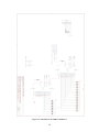
Figure a2 - High Level Schematic of Circuit Board for the Photodiodes
15
Figure a3 - Schematic for the LED Circuit Board
16
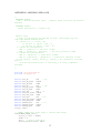
APPENDIX B - ARDUINO CODE (AS IS)
/*
HARDWARE SETUP::
PE6 -- Photodiode pulse input.
enabled)
(digital input with pull-up resistor
SOFTWARE SETUP::
115200 baud serial -- outputs the
General tips:
1. most of the macros are defined in http://www.nongnu.org/avrlibc/user-manual/modules.html
2. _BV(bit) is (1 << bit), eg:
to set bit 0, _BV(0) = 0x0 = 0,
to set bit 4, _BV(4) = 0x10 = 16
3. Idioms for setting bits:
REG |= _BV(bit1); // set bit1 in REG
REG |= _BV(bit1) | _BV(bit2); // set bit1 and bit2 in REG
4. Idioms for clearing bits:
REG &= ~_BV(bit1); // clear bit1 in REG
REG &= ~(_BV(bit1) | _BV(bit2)); // clear bit1 and bit2 in REG
5. Use uint8_t, int8_t, uint16_t, uint32_t, etc instead of int/char.
This is
an 8-bit microcontroller, so use uint8_t or int8_t whenever
possible.
*/
#include <avr/interrupt.h>
#include <inttypes.h>
#define
#define
#define
#define
#define
#define
#define
#define
#define
#define
#define
#define
#define
#define
#define
uint8_t
TLC_LE
TLC_LE_PORT
TLC_LE_DDR
TLC_OE
TLC_OE_PORT
TLC_OE_DDR
TLC_SDI
TLC_SDI_PORT
TLC_SDI_DDR
TLC_CLK
TLC_CLK_PORT
TLC_CLK_DDR
PHOTOD_OUT
PHOTOD_PORT
PHOTOD_DDR
LEDs;
PB0
// 53
PORTB
DDRB
PL0
// 49
PORTL
DDRL
PB2 // 51
PORTB
DDRB
PB1 // 52
PORTB
DDRB
PL2 // 47
PORTL
DDRL
// TIMER1_COMPA_vect fires every 1 second (see setup)
ISR(TIMER4_COMPA_vect) {
uint16_t count = TCNT5;
TCNT5 = 0;
sei(); // enable interrupts
Serial.println(count, DEC);
17
}
void setup() {
Serial.begin(115200);
Serial.println("hi");
// Make sure OE is high initially
TLC_OE_PORT |= _BV(TLC_OE);
// Pin Setup
TLC_SDI_DDR |= _BV(TLC_SDI);
TLC_OE_DDR |= _BV(TLC_OE);
TLC_LE_DDR |= _BV(TLC_LE);
TLC_CLK_DDR |= _BV(TLC_CLK);
// Pin setup:
PHOTOD_DDR &= ~_BV(PHOTOD_OUT);
PHOTOD_PORT |= _BV(PHOTOD_OUT); // enable pull-up resistor on PE6
(T3)
// TIMER1 setup to fire the TIMER1_COMPA_vect interrupt every 1
second
// WGMn[3..0] = 0b1111 - fast PWM mode, OCRnA top
// CSn[2..0] = 0b101 - clock counter at F_CPU / 1024 (prescaler at
1024)
TCCR4A = _BV(WGM41) | _BV(WGM40);
TCCR4B = _BV(WGM43) | _BV(WGM42);
TIMSK4 = _BV(OCIE4A); // enable COMPA interrupt
OCR4A = 8000; //15624; // (1024 / 16e6) * 15625 steps = 1 second
per interrupt
// note that the register should be set to (steps 1)
TCNT4 = 0;
TCCR4B |= _BV(CS42) | _BV(CS40); // start timer, prescaler at 1024
// TIMER3 setup to count pulses on the T3 pin (rising edge)
// WGMn[3..0] = 0b0000 - normal mode
// CSn[2..0] = 0b111 - clock on rising edge of T3
TCNT5 = 0;
TCCR5A = 0;
TCCR5B = _BV(CS52) | _BV(CS51) | _BV(CS50);
// initialize all LEDs to off
SPI_init();
TLC_setByte(1);
// set OE to low
TLC_OE_PORT &= ~_BV(TLC_OE);
sei();
}
void loop() {
if(Serial.available()>0){
char c = Serial.read();
uint8_t on = 0;
switch(c){
case 'o':
18
on = 1;
case 'f':
long m = millis();
while(!Serial.available() && (millis() - m < 50) ){
}
if(!Serial.available()){
Serial.print('e');
Serial.print('\n');
return;
}
char LEDbit = Serial.read()-'0';
if(LEDbit < 0 || LEDbit > 7){
return;
}
if(on){
LEDs |= _BV(LEDbit);
}else{
LEDs &= ~_BV(LEDbit);
}
TLC_setByte(LEDs);
Serial.print('o');
Serial.print(LEDbit,DEC);
Serial.print(' ');
Serial.println(LEDs,BIN);
}
}
}
void SPI_shift8(uint8_t data){
SPDR = data;
while(!(SPSR & _BV(SPIF))){
}
}
void TLC_setByte(uint8_t data){
SPI_shift8(data);
TLC_LE_PORT |= _BV(TLC_LE);
TLC_LE_PORT &= ~_BV(TLC_LE);
}
void SPI_init(){
SPCR = _BV(MSTR) | _BV(SPE);
SPSR = _BV(SPI2X);
}
19