1
RAFA Solutions
Industrial Protocols
Educational Software
InPEduS User Manual
CONTENTS
Introduction.......................................................................................................................................... 2
Required Software................................................................................................................................ 3
Installation of the software .................................................................................................................. 3
Software License and Evaluation ......................................................................................................... 4
License Agreement.............................................................................................................................6
1. Protocol CAN ................................................................................................................................. 10
Exercise №1. Data transmission in CAN protocol................................................................................ 17
Exercise №2. Data request in CAN protocol. ...................................................................................... 19
Exercise №3. Error detection and Error frame transmission in CAN protocol. ...................................... 21
2. Protocol SPI.................................................................................................................................... 23
Exercise №1. Data transmission in SPI protocol.................................................................................. 27
Exercise №2. Data reception in SPI protocol. ..................................................................................... 29
3. Protocol I2C ................................................................................................................................... 31
Exercise №1. Data transmission in I2C protocol. ................................................................................ 35
Exercise №2. Data reception in I2C protocol. ..................................................................................... 37
4. Protocol RS232 .............................................................................................................................. 39
Exercise №1. Data transmission in RS232 protocol............................................................................. 42
Exercise №2. Data reception in RS232 protocol.................................................................................. 44
5. Protocol RS485/422....................................................................................................................... 46
Exercise №1. Data transmission in RS422/485 protocol...................................................................... 49
Exercise №2. Data reception in RS422/485 protocol........................................................................... 51
6. Protocol Modbus ........................................................................................................................... 53
Exercise №1. Data transmission in Modbus protocol.......................................................................... 59
Exercise №2. Error detection in Modbus protocol.............................................................................. 61
7. Protocol GPIB................................................................................................................................. 63
Exercise №1. Data transmission in GPIB protocol. .............................................................................. 69
8. Protocol TCP .................................................................................................................................. 71
Exercise №1. Data transmission in TCP protocol................................................................................. 76
Exercise №2. Data checking in TCP protocol. ..................................................................................... 80
9. Protocol UDP ................................................................................................................................. 82
Exercise №1. Data transmission in UDP protocol................................................................................ 86
Exercise №2. Data checking in UDP protocol...................................................................................... 88
1
© RAFA Solutions, 2014
InPEduS User Manual
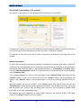
Introduction
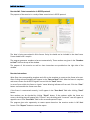
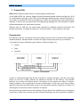
“InPEduS” is educational software, which is intended to help
students learn basics of industrial protocols and interfaces.
Software is combined of interesting and useful exercises and demonstrations, which give a unique
opportunity to deeply understand the structure and operation principles of protocols.
InPEduS software includes 9 popular protocols, which are CAN, GPIB, I2C, Modbus, RS232,
RS485/422, SPI, TCP and UDP.
For each of the protocols from 1 to 3 exercises are designed that serve to test student’s knowledge
and help them to get the full idea of protocols. A demonstration is provided for each protocol, to
visualize working mechanism of protocols. InPEduS also gives opportunity to make reports for
finished exercises. This option can be helpful for trainers as well as for students to have information
about student’s progress.
InPEduS also provides User Manual with full descriptions of all protocols and instructions for
exercises in order to perform them correctly. Software has also an option to open User Manual while
working with protocols. This option makes it even more convenient for students to refresh their
knowledge of protocols while doing exercises.
In conclusion, InPEduS is an adjuvant tool to make studying process of protocols fascinating. All
options introduced above make it an ideal platform to learn industrial protocols course either by
your own or within a class.
2
© RAFA Solutions, 2014
InPEduS User Manual
Required Software
Windows 7
LabVIEW RunTime Engine 2012
MS Word 2010 or higher
Installation of the software
Install the following software:
1. Software “InPEduS” (run setup.exe and follow the instructions).
Please check if you have font “Arial CYR” on your computer. If the font does not exist, you can find it
in the folder with installer.
If you are going to use Russian version of the software before running the software ensure MS
Windows supports Russian keyboard. Open Start -> Control Panel -> Regional and language Options
and make sure that location is set as Russia Location: Россия and in the tab Advanced language for
non-Unicode programs is set - Русский.
After installation is complete restart the computer.
3
© RAFA Solutions, 2014
InPEduS User Manual
Software License and Evaluation
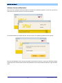
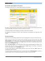
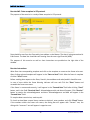
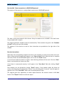
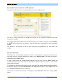
You can use the software without activation for 15 days for evaluation purposes. In this case you will see
notification of days left each time you start the software.
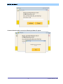
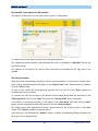
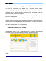
To activate software you should click the “Activate” button. The following window will be opened.
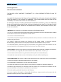
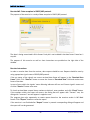
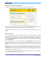
Enter the Serial Number, which you were provided. If entered serial number is correct, the following window
will be opened for final activation. Shown code should be sent to the provided email address to get activation
code.
4
© RAFA Solutions, 2014
InPEduS User Manual
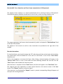
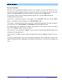
If entered activation code is correct, the following window will appear.
5
© RAFA Solutions, 2014
InPEduS User Manual
License Agreement
END-USER LICENSE AGREEMENT
THIS END-USER LICENSE AGREEMENT ("AGREEMENT") IS A LEGAL AGREEMENT BETWEEN YOU AND THE
LICENSOR.
YOU AGREE TO BE BOUND BY THE TERMS OF THIS AGREEMENT BY INSTALLING, COPYING, OR OTHERWISE
USING THE PRODUCT AS SET FORTH IN THIS AGREEMENT. IF YOU DO NOT AGREE WITH THE TERMS OF THIS
AGREEMENT, YOU SHOULD NOT INSTALL OR USE THE PRODUCT.
BY INSTALLING, COPYING, OR USING THE UPDATES OF THE PRODUCT (''UPDATES''), IF ANY, YOU AGREE TO BE
BOUND BY THE ADDITIONAL LICENSE TERMS THAT MAY ACCOMPANY SUCH UPDATES. IF YOU DO NOT AGREE
TO THE ADDITIONAL LICENSE TERMS THAT ACCOMPANY SUCH UPDATES, YOU SHOULD NOT INSTALL, COPY,
OR USE SUCH UPDATES.
1. Definitions. As used herein, the following terms have the following meanings:
1.1. “You” or “Licensee” means the end user who legally received access to use the Software and the Product
in accordance with the terms and conditions set forth herein.
1.2. “Licensor” means RAFA Solutions.
1.3. “Software” means the computer software provided to You by Licensor in accordance with the terms and
conditions set forth herein.
1.4. “Product” means and includes the Software and all related printed or electronic materials,
documentation, patches and fixes that may be provided or made available to You by Licensor.
1.5. “Permitted Purpose” means the right to use the Product or any portion thereof in accordance with the
terms and conditions of this Agreement solely for the internal use of the Licensee.
2. License Grant. Licensor hereby grants to You and You hereby accept a limited, revocable, non-exclusive,
non-transferable, non-assignable, non-sublicenseable license (hereinafter “License”) to:
2.1. access and use the Product or any portion thereof solely for the Permitted Purpose;
2.2. modify and create derivative works of the Software solely for the Permitted Purpose.
3. License Restrictions. The License is subject to the restrictions below. In particular, You are not allowed to:
3.1. alter any copyright, trademark or patent notice in the Product;
3.2. use Developer’s trademark/s in any way and for any purpose;
3.3. include the Product or any portion thereof in any malicious, deceptive or unlawful programs; or
3.4. distribute, provide access to or otherwise make the Product (as is or modified in accordance with the
terms and conditions set forth herein) available to any third party.
3.5. work around any technical limitations in the Software;
3.6. reverse engineer, decompile or disassemble the Software, except and only to the extent that this
Agreement expressly permits, despite this limitation;
6
© RAFA Solutions, 2014
InPEduS User Manual
3.7. use any components of the Product to run applications not running on the Software;
3.8. make more copies of the Product than specified in this Agreement;
3.9. disclose or distribute the Product or any portion thereof to any third party or publish them for others to
copy;
3.10. rent, lease or lend the Product and/or any developments, improvements, modifications (made by You or
Developer), further updates, upgrades thereof, notwithstanding whether they are made by the Developer,
Installer, Licensor or by You to any third party; or
3.11. use the Product in any other manner not expressly stated in the Permitted Purpose.
4. Geographic Restrictions. You are only permitted to use this Product in the geographic region indicated on
the Product, if any. You should not attempt to install and activate the Software outside of that region.
5. Intellectual Property Rights. The Software, and all copies of the Software, are (a) owned by Developer and
protected by applicable copyright laws and international treaty provisions, and (b) licensed only, and not sold
or leased. You shall not remove or alter any copyright, patent, trademark, or other legal notices or disclaimers
that exist in the Software. All rights not expressly granted to You herein are reserved to Developer.
6. Backup Copy. You may make one backup copy (copies) of the Software. You may use it only to reinstall the
Software.
7. Documentation. Any person that has valid access to your computer or internal network may copy and use
the documentation for your internal, reference purposes.
8. Third Party Programs. The Software may contain third party programs. The license terms with those
programs apply to your use of them.
9. Limitation on and Exclusion of Damages. No Party shall be liable for consequential damages, lost profits,
special, indirect or incidental damages. This limitation applies to anything related to the software, services,
content on third party Internet sites, or third party programs; as well as claims for breach of contract, breach
of warranty, guarantee or condition, strict liability, negligence, or other tort to the extent permitted by
applicable law. It also applies even if repair, replacement or a refund for the Software, if any does not fully
compensate you for any losses; or Licensor knew or should have known about the possibility of the damages.
10. Limited Warranty. If you follow the instructions and the Software is properly licensed, the Software will
perform substantially as described in the Licensor’s materials that you receive in or with the Software. The
limited warranty covers the software for 90 days after acquiring by you. If you receive supplements, updates,
or replacement software during warranty period, they will be covered for the remainder of the warranty.
11. Exclusions from Warranty. This warranty does not cover problems caused by your acts (or failures to act),
the acts of others, or events beyond the reasonable control of the Licensor.
12. Remedy for Breach of Warranty. Licensor will, at its election, either (i) repair or replace the Software at no
charge, within the warranty term, or (ii) accept return of the product(s) for a refund of the amount paid, if any.
7
© RAFA Solutions, 2014
InPEduS User Manual
The developer, Licensor or installer may also repair or replace supplements, updates and replacement
software or provide a refund of the amount you paid for them, if any. These are your only remedies for breach
of the limited warranty.
13. No other Warranties. The limited warranty is the only direct warranty from the developer, Licensor or
installer. The latters give no other express warranties, guarantees or conditions and exclude implied
warranties of merchantability, fitness for a particular purpose and non-infringement.
14. Disclaimer of Warranties. The Limited Warranty referenced herein is the only express warranty made to
you and is provided in lieu of any other express warranties (if any). Except for the Limited Warranty, Licensor
and its suppliers provide the Product and support services (if any) AS IS AND WITH ALL FAULTS, and hereby
disclaim all other warranties and conditions, either express, implied, or statutory, including, but not limited to,
any (if any) implied warranties, duties or conditions of merchantability, of fitness for a particular purpose, of
accuracy or completeness of responses, of results, of workmanlike effort, of lack of viruses, and of lack of
negligence, all with regard to the Product, and the provision of or failure to provide support services. ALSO,
THERE IS NO WARRANTY OR CONDITION OF TITLE, QUIET ENJOYMENT, QUIET POSSESSION, AND
CORRESPONDENCE TO DESCRIPTION OR NON-INFRINGEMENT.
15. EXCLUSION OF INCIDENTAL, CONSEQUENTIAL, AND OTHER DAMAGES. IN NO EVENT SHALL LICENSOR
AND/OR ITS SUPPLIERS, DISTRIBUTORS BE LIABLE FOR ANY SPECIAL, INCIDENTAL, INDIRECT, OR
CONSEQUENTIAL DAMAGES WHATSOEVER (INCLUDING, BUT NOT LIMITED TO, DAMAGES FOR LOSS OF
PROFITS OR CONFIDENTIAL OR OTHER INFORMATION, FOR BUSINESS INTERRUPTION, FOR PERSONAL INJURY,
FOR LOSS OF PRIVACY, FOR FAILURE TO MEET ANY DUTY INCLUDING OF GOOD FAITH OR OF REASONABLE
CARE, FOR NEGLIGENCE, AND FOR ANY OTHER PECUNIARY OR OTHER LOSS WHATSOEVER) ARISING OUT OF
OR IN ANY WAY RELATED TO THE USE OF OR INABILITY TO USE THE PRODUCT, THE PROVISION OF OR FAILURE
TO PROVIDE SUPPORT SERVICES, OR OTHERWISE UNDER OR IN CONNECTION WITH ANY PROVISION OF THIS
AGREEMENT, EVEN IN THE EVENT OF THE FAULT, TORT (INCLUDING NEGLIGENCE), STRICT LIABILITY, BREACH
OF CONTRACT, OR BREACH OF WARRANTY OF LICENSOR OR ANY SUPPLIER, AND EVEN IF LICENSOR OR ANY
SUPPLIER HAS BEEN ADVISED OF THE POSSIBILITY OF SUCH DAMAGES.
16. Limitation of Liability and Remedies. Notwithstanding any damages that you might incur for any reason
whatsoever (including, without limitation, all damages referenced above and all direct or general damages),
the entire liability of Licensor and any of its suppliers, distributors under any provision of this Agreement and
your exclusive remedy for all of the foregoing (except for any remedy of repair or replacement elected by
Licensor with respect to any breach of the Limited Warranty) shall be limited to the greater of the amount
actually paid by you for the Product. The foregoing limitations, exclusions, and disclaimers (including Sections
9 and 10 above and as stated in the Limited Warranty) shall apply to the maximum extent permitted by
applicable law, even if any remedy fails its essential purpose.
17. Consent to use of Data. You agree that Licensor and/or its affiliates may collect and use technical
information you provide as a part of support services, if any, related to the Product. Licensor agrees not to use
this information in a form that personally identifies you.
18. Prerelease Code. The Product or any portion thereof may be identified as prerelease code ("Prerelease
Code"). Such Prerelease Code may be not at the level of performance and compatibility of the final Product.
The Prerelease Code may not operate correctly and may be substantially modified. The grant of license to use
Prerelease Code expires upon availability of the final version (including trial version) of the Product.
8
© RAFA Solutions, 2014
InPEduS User Manual
19. Update License Terms. All updates shall be considered part of the Product and subject to the terms and
conditions of this Agreement. Additional license terms may accompany Updates, as defined above. By
installing, copying, or otherwise using any Update, you agree to be bound by the terms accompanying each
such Update. If you do not agree to the additional license terms accompanying such Updates, you should not
install, copy, or otherwise use such Updates.
20. Entire Agreement. This Agreement (including any addendum or amendment to this Agreement) are the
entire agreement between you and Licensor relating to the Product and the Support Services (if any) and they
supersede all prior or contemporaneous oral or written communications, proposals, and representations with
respect to the Product or any other subject matter covered by this Agreement. To the extent the terms of any
Licensor policies or programs for Support Services conflict with the terms of this Agreement, the terms of this
Agreement shall control.
21. Applicable Law. The law of the country of registration of the Licensor governs the interpretation,
execution and performance of this Agreement.
22. Termination. Without prejudice to any other rights, Licensor may cancel this Agreement if you do not
abide by the terms and conditions of this Agreement, in which case you must destroy all copies of the Product.
9
© RAFA Solutions, 2014
InPEduS User Manual
1. Protocol CAN
CAN (Controller Area Network) protocol was developed by Robert Bosch GmbH company in middle
1980-s and nowadays is broadly popular within IT, “smart house” technologies, vehicle diagnostics,
etc.
Different messages which are being transmitted via network have identifier. Each station decides
whether to receive message or no depending on the identifier. The identifier is defined in “identifier”
field of CAN frame. In this mechanism Receiver address is being identified on receiver itself by
installation of input filters of corresponding ICs.
CAN controllers are connected with differential bus, which has 2 lines for signal transmission: CAN_H
(can-high) and CAN_L (can-low). Logical “0” is detected, if the signal on line CAN_H is higher than on
the line CAN_L and logical “1” if signals on both lines are the same (signals are considered to be equal
if difference between them is less than 0.5V). Use of this differential scheme makes possible the use
of CAN network in very complicated situations. Logical “0” is called dominant bit and logical “1”
recessive. These names reflect priorities of logical “0” and “1” on CAN bus. In case of simultaneous
transmission of logical “0” and “1”, only logical “0” will be registered on bus, and the logical “1” will
be ignored.
CAN protocol is constructed from the following levels.
1. Object level provides message filtering and processing of messages and states.
2. Transport level is the heart of CAN protocol. It provides synchronization, arbitrage, access to
bus, seperation of messages into frames, error detection and error transmittion, and defect
minimization.
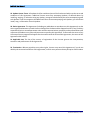
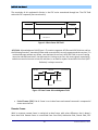
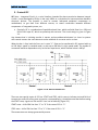
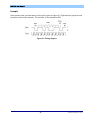
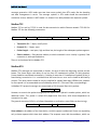
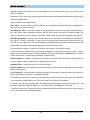
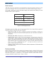
3. Physical level defines the specific ways of signal transmission, electrical levels of signals and
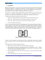
transmission speed. The typical values at 5V supply voltage are illustrated on Figure 1-1, lower
level is dominant and higher is recessive.
High Level (CAN_H)
3,5 V
2,5 V
Low Level
(CAN_L)
1,5 V
Figure 1-1 Signal levels on bus
Maximal distance between nodes is approximately 1 km. Transmission speed can reach up to 1
Mb/sec in case of 60 meter line length. The bus has possibility of galvanic isolation. The galvanic
isolation can be set either between receiver-transmitter buffer and IC providing CAN functions or
between IC and remaining system.
The following frame types are defined for CAN protocol:
10
© RAFA Solutions, 2014
InPEduS User Manual
•
Data Frame transfers data from transmitter to receiver(s);
•
Remote Frame requests data frame from the node with the specified identifier;
•
Error Frame defines the node where bus/network error was detected;
• Overload Frame provides delay between frame transmissions, for data flow control.
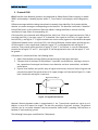
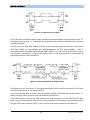
Data Frame
On Figure 1-2 the data frame structure is shown.
Figure 1-2 Data frame structure
Standard frame consists of the following fields:
•
•
•
Start of Frame (SOF). SOF field is located at the start of data frame and remote frame, it
contains one dominant bit.
Arbitration Field. Arbitration field is combined of 11-bit identifier and RTR bit, identifying if
the frame is data frame or remote frame. If the frame is data frame RTR bit is being set to
logical “0” (dominant signal). Identifier is designed for message addressing and is used for
arbitration mechanism. For CAN-2.0A standard 11-bit identifier is used and for CAN-2.0B 29bit identifier is used.
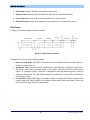
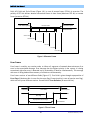
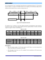
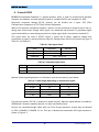
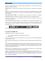
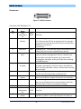
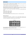
Control Field. Control Field (Figure 1-3) contains 6 bits, 4 of which (DLC0-DLC4) compose Data
Length Code field, which identifies the number of data bytes to be transmitted, 2 other bits
are reserved for later versions of the protocol.
11
© RAFA Solutions, 2014
InPEduS User Manual
Data field
Control field
Arbitration field
r1
r0
DLC3 DLC2 DLC1
Reserved bits
DLC0
CRC field
Data length Code
Figure 1-3 Data Frame Control Field
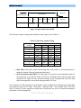
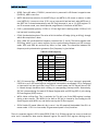
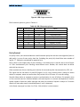
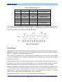
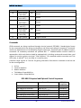
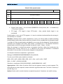
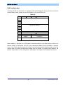
The data byte number coding by data field size code is given in the Table 1-1.
Table 1-1 Data byte number coding
Data byte
number
0
1
2
3
4
5
6
7
8
•
•
DCL3
dom.
dom.
dom.
dom.
dom.
dom.
dom.
dom.
rec.
Data field size code
DCL2
DCL1
dom.
dom.
dom.
dom.
dom.
rec.
dom.
rec.
rec.
dom.
rec.
dom.
rec.
rec.
rec.
rec.
dom.
dom.
DCL0
dom.
rec.
dom.
rec.
dom.
rec.
dom.
rec.
dom.
Data Field. Data field contains transmitting data, and number of transmitting bytes is
defined in Control Field and cannot be more than 8.
Cyclic redundancy check (СRC). CRC field (Figure 1-4) contains cyclic redundancy code, for
error detection in all previous fields of the frame, including start bit. Each receiver node
calculates CRC value for each received message. If the calculated CRC and CRC value
within message differ, the receiver node generates CRC Error.
For calculation of CRC polynomial, the polynomial, which coefficients are being given through data
flow combined from bits of fields: “Start field”, “Arbitrate Field”, “Data Control Field” and “Data
field” (if exists) (15 least sygnificant coefficients of polynimial are set to 0) should be devided to
polynomial of the following form:
x15 + x14 + x10 + x8 + x 7 + x 4 + x 3 + 1
12
© RAFA Solutions, 2014
InPEduS User Manual
The remainder of this polynomial division is the CRC series transmitted through bus. The CRC field
ends with CRC separator (one recessive bit).
Data
CRC field
ACK field
Control Field
CRC Delimiter
CRC Sequence
Figure 1-4 Data frame CRC field
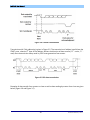
ACK Field. Acknowledgment field (Figure 1-5) contains segments ACK Slot and ACK Delimiter and has
the following functions: transmitter node sends a recessive bit on each segment and the receiver, if it
received message without any failure, sets dominant bit on line in ACK Slot Field. In case of setting
recessive and dominant levels, the dominant bit is being set on line, this event signals transmitting
node that transmission was successful and there is no need for repeat. Second bit of this field (ACK
Delimiter) is always recessive.
ACK field
CRC field
End of frame
ACK delimiter
ACK slot
Figure 1-5 Data Frame Acknowledgment Field
•
End of Frame ( EOF). End of Frame is set in data frame and remote frame and is compound of
seven recessive bits.
Remote Frame
With its structure remote frame is analogical to data frame, with minor difference, that it doesn’t
have data field. Remote frame is constructed from: Start field, Arbitration field, Control field, CRC
13
© RAFA Solutions, 2014
InPEduS User Manual
field, ACK field and End of frame (Figure 1-6). In case of remote frame, RTR bit is recessive. The
polarity of RTR bit defines whether transmitted frame is data frame (dominant RTR bit) or remote
frame (recessive RTR bit).
Remote frame
Inter frame space
Inter frame space
Overload frame
Start of frame
Arbitration field
Control field
CRC field
ACK field
End of frame
Figure 1-6 Remote Frame
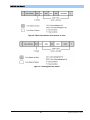
Error Frame
Error frame is used by any receiver node, to inform all segments of network about existence of an
error in the transmitted message. Error message has the highest priority in the system, it is being
transmitted right after error is detected and is received by all devices simultaneously. The message
with error is being deleted from memory of all devices simultaneously.
Error frame consists of two different fields (Figure 1-7). First field is given through superposition of
Error Flags (6 dominant bits in case of active error flag/ 6 recessive bits in case of passive error flag),
which are set by two different stations. Second field is Error Delimiter (8 recessive bits).
Data frame
Error frame
Interframe space
Overload frame
Error flag
Superposition of error flags
Error delimiter
Figure 1-7 Error Frame
14
© RAFA Solutions, 2014
InPEduS User Manual
Overload Frame
Overload frame consists of two fields: overload flag and delimiter field. There are several conditions
in case of which transmit of overload frame is being operated:
•
Receiver overload, which requires increase of delays between received messages.
•
Dominant bit detection in place of first and second bits of delay between frames.
Interframe Space (IFC) is being set between data frames, calling frame and any other frames.
Opposite to this, there is no delay before overload frame and error frame, which speeds up receive
of these fields.
Interframe Space consists of Intermission (3 recessive bits) and Bus Idle (of arbitrary length) and in
case of devices passive to error, which have operated transmit of last message, Suspend
Transmission.
Error Detection in CAN protocol
CAN protocol defines five methods of error detection in network:
• Bit monitoring
• Bit stuffing
• Frame check
• ACKnowledgement Check
• CRC Check
Bit monitoring – each node compares transmitted bit with the bit on the bus during bit transmission
to network. Node generates Bit Error if these values do not equal. This mechanism of error detection
is turning off during arbitration field transmission.
Bit stuffing – After transmit of five serial equivalent bits, transmitter automatically puts in flow a bit
of opposite polarity. Message receivers automatically delete these bits before message processing. If
the 6-th bit of the same polarity is detected, bit overload error is flagged. If the error is detected, the
node sends error message and interrupts the transmission. In this case transmitter repeats message
transfer, which protects all nodes from error generation and provides data consistency within
network.
Frame check – some segments of CAN message have equal values within all message types. This
means that CAN protocol defines what voltage levels should appear on the bus and when. If the
message format is broken, nodes generate Form Error.
ACKnowledgement Check – each node sends to network dominant (0) bit after receiving correct
message. If this action doesn’t take place, transmitting node registers Acknowledgement Error.
CRC Check – each CAN message has within it CRC sum, and each receiver node calculates CRC value
for each received message. If the calculated CRC value does not equal to the value of CRC in the
message, receiver node generates CRC Error.
15
© RAFA Solutions, 2014
InPEduS User Manual
Access Control (bitwise arbitration)
In CAN protocol all nodes get the message from transmitter node and confirm it. Each time, when
bus is transfer free, a node can start transmission. Next transmission can be started only after
current transmission process is finished. If two or more nodes start transferring simultaneously, the
conflict is being resolved in terms of non-destructive bitwise algorithm of arbitration, which uses the
arbitration field.
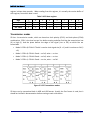
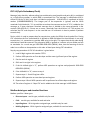
11-bit identifier field is transferred from the most significant to the least significant bit. During
transmission of arbitration field each transmitter controls current level on the bus, which it should
transfer. If the values equal, node then can continue transmission. If a recessive bit was transmitted,
and dominant bit is detected on the bus, transmission should stop immediately and the node loses
transmission access (Figure 1-8). This node can attempt to start new transfer only after current
transfer is finished.
Figure 1-8 Bitwise Arbitration Example
To conclude, the priority is defined not by transmitter or receiver nodes but by the value of identifier
within the message. The smallest identifier has the highest priority. From operating nodes, only the
node with the smallest identifier value can be responsible for decisions made.
The other opportunity of the arbitration mechanism is used in the highest level network of
DeviceNet. In this network the maximum number of nodes is 64, and the least significant digits of the
identifier are used for addressing, and the most significant digits are specified for message type
coding. The message with 0 in the most significant bit will occupy the bus first, independent on
receiver node address. This, in turn, provides transfer of first type messages at first, independent on
transmitter and receiver addresses.
16
© RAFA Solutions, 2014
InPEduS User Manual
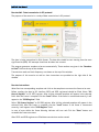
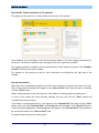
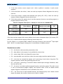
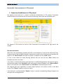
Exercise №1. Data transmission in CAN protocol.
The purpose of the exercise is a study of data transmission in CAN protocol.
The data is being transmitted in 8-bit format. The data bits should be sent starting from the most
significant bit (MSB).
The program generates numbers to be sent automatically. These numbers are given in the “Numbers
to Send” field on the top of the window.
The purpose of this exercise as well as short instructions are provided on the right side of the
window.
Exercise Instructions
Write Data into corresponding template and click on the template to construct the frame to be sent.
After clicking selected template will appear in the “Data to Send” field. After the frame is complete
click the “Send” button.
In case of error within the frame Warning Indicator will turn red. Click the “Clear” button and
assemble the frame once more. You can send all the numbers within one frame or each number
within separate frames.
To calculate the CRC use calculator in the bottom of the window. Write down the polynomial in the
“CRC Polynomial” field. Fill the “Data” field, and click “Calculate CRC” button afterwards.
If the frame is constructed correctly, it will appear in the “Sent Data” field after clicking “Send”
button. Sent numbers can be checked by clicking “Check” button. If the numbers within the frame
are correct, the dialog box will appear with “Correct!” text, the dialog with “Incorrect!” text will
appear in opposite case. Clear “Data to Send” and “Sent Data” fields in this case and repeat all steps.
17
© RAFA Solutions, 2014
InPEduS User Manual
The program gives also opportunity to create reports based on the exercise results in MS Word
format. Click “Report” button to create the report.
If the exercise is not finished after “Report” button is pressed corresponding dialog will appear and
the report will not be generated.
If the exercise is finished correctly, window will appear after pressing “Report” button to fill user's
name.
The report includes protocol name, exercise number and purpose, user's name, date, as well as the
image of constructed frame, depending on the purpose of the exercise. Save the file in any folder you
want.
18
© RAFA Solutions, 2014
InPEduS User Manual
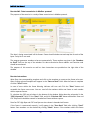
Exercise №2. Data request in CAN protocol.
The purpose of the exercise is the study of data request in CAN protocol.
To request data remote frame should be sent with given identifier.
The program generates identifier code automatically, which is displayed in “Identifier” field at the
top of the window.
The purpose of this exercise as well as short instructions are provided on the right side of the
window.
Exercise Instructions
Write Data into corresponding templates and click on the templates to construct the remote frame.
After clicking, selected template will appear in the “Data to Send” field. After the frame is complete
click the “Send” button.
In case of error within the frame Warning Indicator will turn red. Click the “Clear” button and
assemble the frame once more.
To calculate the CRC use calculator in the bottom of the window. Write down the polynomial in the
“CRC Polynomial” field. Fill the “Data” field, and click “Calculate CRC” button afterwards.
If the frame is constructed correctly, it will appear in the “Sent Data” field after clicking “Send”
button and the received data frame will appear in the field “Received Data”.
The program gives also opportunity to create reports based on the exercise results in MS Word
format. Click “Report” button to create the report.
If the exercise is not finished after “Report” button is pressed corresponding dialog will appear and
the report will not be generated.
19
© RAFA Solutions, 2014
InPEduS User Manual
If the exercise is finished correctly, window will appear after pressing “Report” button to fill user's
name.
The report includes protocol name, exercise number and purpose, user's name, date, as well as the
image of constructed frame, depending on the purpose of the exercise. Save the file in any folder you
want.
20
© RAFA Solutions, 2014
InPEduS User Manual
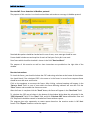
Exercise №3. Error detection and Error frame transmission in CAN protocol.
The purpose of this exercise is to check received data and to send error frame in CAN protocol.
Received data packet should be checked and in case of error, active error flag should be sent.
The program generates the frame to check automatically, which is displayed in “Received Data” field
at the top of the window.
The purpose of this exercise as well as short instructions are provided on the right side of the
window.
Exercise Instructions
To check the frame, you should calculate the CRC code using calculator at the button of the window.
You should check if the calculated CRC is the same as in the frame. In case of error “Error frame”
should be sent.
Click on the templates to construct the frame. After clicking, selected template will appear in the
“Data to Send” field. In case of error within the frame Warning Indicator will turn red. Click the
“Clear” button and assemble the frame once more.
After the frame is complete click the “Send” button, the frame will appear in the “Sent Data” field.
The program gives also opportunity to create reports based on the exercise results in MS Word
format. Click “Report” button to create the report.
If the exercise is not finished after “Report” button is pressed corresponding dialog will appear and
the report will not be generated.
21
© RAFA Solutions, 2014
InPEduS User Manual
If the exercise is finished correctly, window will appear after pressing “Report” button to fill user's
name.
The report includes protocol name, exercise number and purpose, user's name, date, as well as the
image of constructed frame, depending on the purpose of the exercise. Save the file in any folder you
want.
22
© RAFA Solutions, 2014
InPEduS User Manual
2. Protocol SPI
SPI (Serial Peripheral Bus) is an interface for serial data transfer between chips, which was developed
by Motorola. Nowadays it is widely used in productions of many companies. SPI is also called fourwire interface. SPI bus is organized by master - slave principle. Microcontroller usually serves as
master and different chips, memories, specialized controllers, etc. are slaves.
SPI interface is a protocol of data transfer between two shift registers, each of which is both a
receiver and a transmitter simultaneously. The generation of bus synchronization signal is a
precondition for data transfer through SPI bus. This signal can be generated only by master.
4 signals are involved in data transmission with SPI protocol.
MOSI or SI —Master Out Slave In. Serves for data transmission from master to slave.
MISO or SO —Master In Slave Out. Serves for data transfer from slave to master.
SCLK or SCK —Serial Clock. Serves for transmission of clock signal to slaves.
CS or SS —Chip Select, Slave Select.
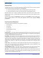
There are 3 connection types on SPI bus. The simplest connection, where only 2 chips are included, is
shown on Figure 2-1. Here, master sends data by MOSI line, synchronized with SCLK signal, which is
as well generated by master. The slave receives transmitted data bits by fronts of received
synchronization signal, simultaneously with this process slave sends its data packet. If there is no
need of response data transfer, the illustrated scheme can be simplified, by excluding the MISO line.
Master SPI
SCLK
MOSI
MISO
SS
Slave SPI
SCLK
MOSI
MISO
SS
Figure 2-1 Simplest connection on SPI bus
If there is need for connection of several chips to SPI bus, either parallel connection or cascaded
(serial) connection is used. In case of cascaded connection, multiple slaves can be connected to one
line.
Standard algorithm for SPI functioning is given below.
1. Master sets low level on the SS line, to which linked slave is connected.
2. Master generates clock signal, switching signal level of SCLK between “0” and “1”. Master
puts the right level of MOSI signal simultaneously with every SCKL level change, so during
each clock pulse it sends one data bit to slave.
3. Slave puts right MOSI level with each SCKL level change, so it sends to master one bit during
each clock pulse.
4. Master sets high signal level on SS line, to finish the transmission.
23
© RAFA Solutions, 2014
InPEduS User Manual
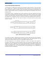
SPI is full duplex bus. Data is transferred in both directions simultaneously (Figure 2-2). The speed of
the bus usually is in range of 1-50 MHz. Because of its simplicity, SPI has become widely used in
different electrical devices such as sensors, memory chips, etc.
Master
MSB
LSB
MISO MISO
Slave
MSB
8-bit shift register
LSB
8-Bit shift register
MOSI MOSI
SCK
SS
SPI Clock generation
SCK
SS
Vcc
Figure 2-2 Full duplex data transfer
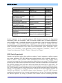
SPI interface uses 2 registers to set data transfer parameters (synchronization signal frequency,
transmission mode, etc.): control register (SPCR) and status register (SPSR). SPI status and control
registers are given in Table 2-1 and Table 2-2.
Table 2-1. SPCR
Digit
Flag
Read/Write
Init. value
7
SPIE
R/W
0
6
SPE
R/W
0
5
DORD
R/W
0
4
MSTR
R/W
0
3
CPOL
R/W
0
2
CPHA
R/W
0
1
SPR1
R/W
0
0
SPR0
R/W
0
3
R
0
2
R
0
1
R
0
0
SPI2X
R/W
0
Table 2-2. SPSR
Digit
Flag
Read/Write
Init. value
7
SPIF
R
0
6
WCOL
R
0
5
R
0
4
R
0
SPI registers
•
SPIE: SPI interrupt enable. If in SPI status register the SPIF flag is set, then setting this bit
(SPIE=1) will bring to SPI interruption processing.
•
SPE: SPI enable. If this flag is set, SPI is enabled. This bit should be set if SPI must be used
regardless of the mode.
24
© RAFA Solutions, 2014
InPEduS User Manual
•
DORD: Data shift order. If DORD=1, transmission is processed in LSB format. In opposite case
(DORD=0), MSB is sent first.
•
MSTR: Master/slave selection. If the MSTR flag is set (MSTR=1), SPI serves as master, in other
case (MSTR=0), it serves as slave. If SS is set as input and it had low level, when MSTR was 1,
the MSTF bit is cleared automatically and SPIF flag (interrupt) is set to 1 in SPSR register. To
set SPI to master mode, user should provide programmatic installation of MSTR bit.
•
CPOL: synchronization polarity. If CPOL=1, SCK has high level in waiting mode. If CPOL=0, SCK
has low level in waiting mode.
•
CPHA: Synchronization phase. The value of this bit defines SCK edge (rising or falling), through
which data acquisition is done.
•
SPR1, SPR0: SPI synchronization frequency selection bits (1 and 0). These bits together with
SPI2X flag, which is set in status register, set the synchronization frequency on SCK in master
mode. SPR1 and SPR0 do not have any effect in slave mode. The connection between SCK
frequency and synchronization generator (fosc) frequency is given below:
Table 2-3. SCK frequency
SPI2X SPR1 SPR0
0
0
0
0
1
1
1
1
0
0
1
1
0
0
1
1
0
1
0
1
0
1
0
1
SCK
frequency
fosc/4
fosc/16
fosc/64
fosc/128
fosc/2
fosc/8
fosc/32
fosc/64
•
SPIF: SPI interrupt flag. This flag is set when serial transmission is over. Interrupt is generated
if SPIE bit is set in SPI control register and general interruptions are allowed. If SS is configured
as input and it has low signal level, than if SPI is in master mode, the SPIF flag will be set. SPIF
is cleared through hardware when shifting to corresponding interrupt vector. Alternatively,
SPIF bit is cleared during first read of SPI Status Register with set SPIF flag (SPIF=1), also during
SPI Data Register (SPDR) access.
•
WCOL: Write collision flag. This is read only bit. This bit is set if the SPDR register is written
during a data transfer. The WCOL bit (as well as SPIF bit) is cleared by first reading the SPI
Status Register with WCOL set, and then accessing the SPI Data register.
•
SPI2X: Double SPI speed. When this bit is set to 1, the SPI speed will be doubled if the SPI is in
master mode. If SPI is in slave mode, SPI guaranteed speed is fosc/4 and less.
There is a separate register in SPI for data (SPDR) (Table 2-4). SPI data register has access to read and
write and is intended for data transfer between register file and SPI shift register. Writing to this
25
© RAFA Solutions, 2014
InPEduS User Manual
register initiates data transfer. When reading from this register, it is actually the receive buffer of
shift register, from which data is read.
Table 2-4 SPI data register
Digit
Read/Write
Init. value
7
MSB
R/W
x
6
5
4
3
2
1
R/W
x
R/W
x
R/W
x
R/W
x
R/W
x
R/W
x
0
LSB
R/W
x
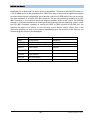
Transmission modes
SPI has 4 transmission modes, which are based on clock polarity (CPOL) and clock phase (CPHA)
combinations. CPOL is the level on tact line before starting and after finishing the transmission: low
(0) or high (1). And the phase defines the edge of the signal (rise or fall) on which bits are
transmitted.
•
Mode 0: CPOL=0, CPHA=0. The bit is read on clock signal rise (0 -> 1) and it is written on fall (1
->0).
•
Mode 1: CPOL=0, CPHA=1. Read — on fall, write — on rise.
•
Mode 2: CPOL=1, CPHA=0. Read — on fall, write — on rise.
•
Mode 3: CPOL=1, CPHA=1. Read — on rise, write — on fall.
Figure 2-3 SPI Transmission modes
SPI data can be transmitted both in MSB and LSB formats. Usually the first format is used, but it
should be clarified in documentation before starting to work with device.
26
© RAFA Solutions, 2014
InPEduS User Manual
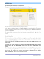
Exercise №1. Data transmission in SPI protocol.
The purpose of the exercise is a study of data transmission in SPI protocol.
The data is being transmitted in 8-bit format. The data bits should be sent starting from the most
significant bit (MSB). SPI interrupts should not be taken into account.
The program generates numbers to be sent automatically. These numbers are given in the “Numbers
to Send” field on the top of the window.
Transmission mode and clock frequency are shown on the top of the window.
The purpose of this exercise as well as short instructions are provided on the right side of the
window.
Exercise Instructions
Write Data into corresponding template and click on the template to construct the frame to be sent.
Before sending the data by SPI interface SPCR and SPSR registered should be filled. Select “SPI
Control Register” to fill SPCR register. After clicking selected template will appear in the selected
field. After the frame is complete click the “Load” button. If the frame is constructed correctly, it will
appear in the “SPCR Register” field.
Select “SPI Status Register” to fill SPSR register. After clicking selected template will appear in the
selected field. After the frame is complete click the “Load” button. If the frame is constructed
correctly, it will appear in the “SPSR Register” field.
In case of error within the frame Warning Indicator will turn red. Click the “Clear” button and
assemble the frame once more.
After SPCR and SPSR registers are filled data transmission can be started.
27
© RAFA Solutions, 2014
InPEduS User Manual
Select “SPI Data Register” and click on the data template. After clicking selected template will appear
in the selected field.
Sent numbers can be checked by clicking “Check” button. If the numbers within the frame are
correct, the dialog box will appear with “Correct!” text, the dialog with “Incorrect!” text will appear in
opposite case. Clear all fields in this case and repeat all steps.
The program gives also opportunity to create reports based on the exercise results in MS Word
format. Click “Report” button to create the report.
If the exercise is not finished after “Report” button is pressed corresponding dialog will appear and
the report will not be generated.
If the exercise is finished correctly, window will appear after pressing “Report” button to fill user's
name.
The report includes protocol name, exercise number and purpose, user's name, date, as well as the
image of constructed frame, depending on the purpose of the exercise. Save the file in any folder you
want.
28
© RAFA Solutions, 2014
InPEduS User Manual
Exercise №2. Data reception in SPI protocol.
The purpose of the exercise is a study of data reception in SPI protocol.
The data is being transmitted in 8-bit format. The data bits should be sent starting from the most
significant bit (MSB). SPI interrupts should not be taken into account.
Transmission mode and clock frequency are shown on the top of the window.
The purpose of this exercise as well as short instructions are provided on the right side of the
window.
Exercise Instructions
Write Data into corresponding template and click on the template to construct the frame to be sent.
Before receiving the data by SPI interface SPCR and SPSR registered should be filled. Select “SPI
Control Register” to fill SPCR register. After clicking selected template will appear in the selected
field. After the frame is complete click the “Load” button. If the frame is constructed correctly, it will
appear in the “SPCR Register” field.
Select “SPI Status Register” to fill SPSR register. After clicking selected template will appear in the
selected field. After the frame is complete click the “Load” button. If the frame is constructed
correctly, it will appear in the “SPSR Register” field.
In case of error within the frame Warning Indicator will turn red. Click the “Clear” button and
assemble the frame once more.
To receive the data, any data should be sent. To send the data select “SPI Data Register” and click on
the data template. After clicking selected template will appear in the selected field.
29
© RAFA Solutions, 2014
InPEduS User Manual
If there are no any errors in the filled registers, data will appear in the “Sent Data” field after clicking
“Send” button.
Click the “Receive” button to receive the data. Data is shown in binary format. To check received
data convert binary numbers to decimal, enter numbers and click “Check” button. If the numbers
within the frame are correct, the dialog box will appear with “Correct!” text, the dialog with
“Incorrect!” text will appear in opposite case.
The program gives also opportunity to create reports based on the exercise results in MS Word
format. Click “Report” button to create the report.
If the exercise is not finished after “Report” button is pressed corresponding dialog will appear and
the report will not be generated.
If the exercise is finished correctly, window will appear after pressing “Report” button to fill user's
name.
The report includes protocol name, exercise number and purpose, user's name, date, as well as the
image of constructed frame, depending on the purpose of the exercise. Save the file in any folder you
want.
30
© RAFA Solutions, 2014
InPEduS User Manual
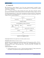
3. Protocol I2C
I2C (Inter - Integrated Circuit) is a serial interface intended for data transmission between integral
circuits. It was developed by Philips in the early 1980s as a simple bus for interconnections between
electronic devices. The protocol is used to connect low-speed peripheral components to
motherboard, to get data from different sensors, to create connections between different
components of integrated systems, etc.
•
Physically I2C is a combination of two bidirectional lines, which are Serial Data Line – SDA and
Serial Clock Input SC, which are pulled up with resistors. The circuit design is given in Figure
3-1.
Any element that is initiating transfer is master, and any addressed element is a slave. In systems
with several masters the same element can be used both as a master and as a slave.
When the bus is free, both the lines are in state “1”. Data can be transferred in I2C protocol with up
to 100 kbit/s speed in standard mode, or with up to 400 kbit/s in high speed mode. The number of
connected interfaces dependents only on the bus capacitance, which maximal value is 400 pF.
Figure 3-1 I2C device connections
There are two special states of I2C bus: START and STOP, which serve to indicate start and finish of
transmission and shift of bus state to inactive, correspondingly. It should be noted that before setting
the START state, signals on SDA and SCL lines can be arbitrary (Figure 3-2).
START state – shifts SDA line from “1” to “0” if the state of SCL is “1”.
STOP state – shifts SDA line from “0” to “1” if the state of SCL is “1”.
These two states are always generated by master.
31
© RAFA Solutions, 2014
InPEduS User Manual
Figure 3-2 START and STOP states
As the bus lines are pulled to power supply, the devices should pull down lines to ground to send “0”,
and release them to send “1”. Connection for cooperative work of devices with this kind of inclusion
is called wired AND.
Transfers are done byte wise. Number of bytes to be sent during single transmission is not limited.
Each byte should be accompanied with acknowledgement bit ACK (ACKnowledge). Data is
transmitted started from Most Significant Bit (MSB) (Figure 3-3). If the receiver is not able to receive
the full byte of information, it is giving ACK signal, which is used by transmitter to synchronize and
signalize the receiver fault (or absence).
Figure 3-3 Data transmission through I2C bus
Transmitter sets the SDA line to “1” during synchronization pulse to confirm the transfer. In this case
the receiver should set “0” on SDA (Figure 3-4).
If the slave receiver does not confirm the slave address (NACK), the SDA data line should remain “1”.
Master can give STOP signal after this and repeat the transmission.
If the slave receiver confirms the slave address, but, after some time, it is not able to receive data
bytes, master should stop the transmission. During reception of the last byte in the sequence master
can give STOP state instead of signal. In this case the slave receiver should free the data line.
32
© RAFA Solutions, 2014
InPEduS User Manual
Figure 3-4 Transfer confirmation
Transmission with 7-bit addressing is given in Figure 3-5. The transmission of address byte follows the
START state, wherein 8th byte of the address defines the direction of data transfer (“0” – write, “1” read). Data transmission always ends by STOP state generation from master.
Figure 3-5 I2C data transmission
Examples of data transfer from master to slave as well as data reading by master from slave are given
below (Figure 3-6 and Figure 3-7).
33
© RAFA Solutions, 2014
InPEduS User Manual
Figure 3-6 Data transmission from master to slave
Figure 3-7 Reading data by master
34
© RAFA Solutions, 2014
InPEduS User Manual
Exercise №1. Data transmission in I2C protocol.
The purpose of the exercise is a study of data transmission in I2C protocol.
Data should be sent from Master to the Slave with given address. The data is being transmitted in 8bit format. The data bits should be sent starting from the most significant bit (MSB).
The program generates numbers to be sent automatically. These numbers are given in the “Numbers
to Send” field on the top of the window.
The purpose of this exercise as well as short instructions are provided on the right side of the
window.
Exercise Instructions
Write Data into corresponding template and click on the template to construct the frame to be sent.
After clicking selected template will appear in the “Data to Send” field. After the frame is complete
click the “Send” button.
Before sending the data to the slave Start bit, slave address and write/read bit should be sent.
In case of error within the frame Warning Indicator will turn red. Click the “Clear” button and
assemble the frame once more.
If the frame is constructed correctly, it will appear in the “Formed Data” field after clicking “Send”
button, and in the field “Received Data” Acknowledgement bit will appear. Click “Receive” button to
receive the Acknowledgement. Acknowledgement will appear in the “Formed Data” field and data to
be sent will be shown in the “Data to Send” field.
To stop the data transmission, send stop bit.
35
© RAFA Solutions, 2014
InPEduS User Manual
Sent numbers can be checked by clicking “Check” button. If the numbers within the frame are
correct, the dialog box will appear with “Correct!” text, the dialog with “Incorrect!” text will appear in
opposite case. Clear “Formed Data” field in this case and repeat all steps.
The program gives also opportunity to create reports based on the exercise results in MS Word
format. Click “Report” button to create the report.
If the exercise is not finished after “Report” button is pressed corresponding dialog will appear and
the report will not be generated.
If the exercise is finished correctly, window will appear after pressing “Report” button to fill user's
name.
The report includes protocol name, exercise number and purpose, user's name, date, as well as the
image of constructed frame, depending on the purpose of the exercise. Save the file in any folder you
want.
36
© RAFA Solutions, 2014
InPEduS User Manual
Exercise №2. Data reception in I2C protocol.
The purpose of the exercise is a study of data reception in I2C protocol.
Data should be sent from the Slave with given address to the Master. The data is being transmitted in
8-bit format. The data bits should be sent starting from the most significant bit (MSB).
The purpose of this exercise as well as short instructions are provided on the right side of the
window.
Exercise Instructions
Write Data into corresponding template and click on the template to construct the frame to be sent.
After clicking selected template will appear in the “Data to Send” field. After the frame is complete
click the “Send” button.
Before sending data request to the Slave, Start bit, slave address and write/read bit should be sent.
In case of error within the frame Warning Indicator will turn red. Click the “Clear” button and
assemble the frame once more.
If the frame is constructed correctly, it will appear in the “Formed Data” field after clicking “Send”
button, and in the field “Received Data” Acknowledgement bit and data will appear. Click “Receive”
button to receive the acknowledgement and data. Acknowledgement and data will appear in the
“Formed Data” field.
To stop the data transmission, send stop bit.
To check received data convert binary numbers to decimal, enter numbers and click “Check” button.
If the numbers within the frame are correct, the dialog box will appear with “Correct!” text, the
dialog with “Incorrect!” text will appear in opposite case.
37
© RAFA Solutions, 2014
InPEduS User Manual
The program gives also opportunity to create reports based on the exercise results in MS Word
format. Click “Report” button to create the report.
If the exercise is not finished after “Report” button is pressed corresponding dialog will appear and
the report will not be generated.
If the exercise is finished correctly, window will appear after pressing “Report” button to fill user's
name.
The report includes protocol name, exercise number and purpose, user's name, date, as well as the
image of constructed frame, depending on the purpose of the exercise. Save the file in any folder you
want.
38
© RAFA Solutions, 2014
InPEduS User Manual
4. Protocol RS232
RS-232 (Recommended Standard) is a popular protocol, which is used for communication between
computer and modems and other peripheral devices. Standard RS-232 was introduced in 1962.
Equipment connected through RS-232 protocol can be divided into 2 types: DCE (Data
Communication Equipment) и DTE (Data Terminal Equipment).
With RS-232 protocol information between 2 devices can be transferred in distances up to 20m, as
during data transmission through cable signals are weakened and distorted. To guarantee higher
signal sustainability to noises during transmission, higher signal levels are used than standard 5V.
Two signal levels are used in RS-232: logical 1 (mark) and 0 (space). Negative voltage level
corresponds to logical 1, and the positive to logical 0. Voltage values used in this protocol are given in
Table 4-1 and Table 4-2.
Table 4-1. Data signal levels
Level
Logical 0
Logical 1
Undefined
Transmitter
Receiver
From +5V to +15V From +3V to +25V
From -5V to -15V
From -3V to -25V
From -3V to +3V
Table 4-2. Command signal levels
Signal
"Off"
"On"
Driver
From -5V to -15V
From 5V to 15V
Terminator
From -3V to -25V
From 3V to 25V
Maximal cable length dependence on information transmission speed is given below:
Table 4-3. Cable length depending on transmission speed
Speed [baud]
19 200
9 600
4 800
2 400
Max length [foot]
50
500
1000
3000
Max length [meters]
15
150
300
900
Transmission speed in RS-232 is measured in bauds (bit/sec). Maximal speed defined in standard is
20000 bauds. However nowadays devices can work considerably faster.
Devices are connected through cables with 9 or 25 pin D type connectors. Usually they are denoted
as DB-9, CANNON 9, CANNON 25, etc. Each pin is denoted and numerated. DB-9 type connector is
shown in Figure 4-1.
39
© RAFA Solutions, 2014
InPEduS User Manual
Figure 4-1 DB-9 type connector
DB-9 connector pinout is given in Table 4-4.
Table 4-4. DB-9 Connector pinout
Contact
1
2
3
4
5
6
7
8
9
Abbreviation
DCD
RXD
TXD
DTR
GND
DSR
RTS
CTS
RI
Direction
In
In
Out
Out
--In
Out
In
In
Name
Data Carrier Detect
Received Data
Transmitted Data
Data Terminal Ready
Ground
Data Set Ready
Request To Send
Clear To Send
Ring Indicator
Parity Control
For parity check, two connected devices should calculate parity bits with the same algorithm (even or
odd parity). In case of even parity, data bits (including the parity bit) should have even number of
logical “1”. Odd parity corresponds to opposite case.
Parity check is the simplest way of error checking. It can detect error in one bit, but in case of errors
in 2 bits simultaneously this checking cannot detect errors. Besides, this control does not define
which bit has the error.
Other mechanisms of error checking are inclusion of start and stop bits into transmission, CRC, etc.
The signal line has two states: On and Off (logical 1 or 0). Line in waiting state is always on. When
device or computer wants to transfer data, they set the line in Off state, as a start bit setting.
Stop bit allows device or computer to process synchronization in case of failures. For example, noise
on line can hide start bit. Duration between start and stop bits is constant and depends on transfer
speed, number of data bits within message and parity bit existence. Stop bit is always on. If receiver
detects off state when stop bit should be present, error is detected.
In the frame stop signal can have 1 or 2 bits. 1 bit selection is more common.
40
© RAFA Solutions, 2014
InPEduS User Manual
Example
Data structure with synchronization clock signal is given on Figure 4-2. Eight data bits, parity bit and
stop bit are used in this example. This structure is also denoted as 8Е1.
Figure 4-2 Timing diagram
41
© RAFA Solutions, 2014
InPEduS User Manual
Exercise №1. Data transmission in RS232 protocol.
The purpose of the exercise is a study of data transmission in RS232 protocol.
The data is being transmitted in 8-bit format. Parity bit should not be included in the data frame.
Frame should have 1 stop bit.
The program generates numbers to be sent automatically. These numbers are given in the “Numbers
to Send” field on the top of the window.
The purpose of this exercise as well as short instructions are provided on the right side of the
window.
Exercise Instructions
Write Data into corresponding template and click on the template to construct the frame to be sent.
After clicking selected template will appear in the “Data to Send” field. After the frame is complete
and correct states for the RS232 signals are set click the “Send” button.
In case of error within the frame or signals' states Warning Indicator will turn red. Click the “Clear”
button and assemble the frame once more.
If the frame is constructed correctly, it will appear in the “Sent Data” field after clicking “Send”
button.
Sent numbers can be checked by clicking “Check” button. If the numbers within the frame are
correct, the dialog box will appear with “Correct!” text, the dialog with “Incorrect!” text will appear in
opposite case. Clear “Sent Data” field in this case and repeat all steps.
The program gives also opportunity to create reports based on the exercise results in MS Word
format. Click “Report” button to create the report.
42
© RAFA Solutions, 2014
InPEduS User Manual
If the exercise is not finished after “Report” button is pressed corresponding dialog will appear and
the report will not be generated.
If the exercise is finished correctly, window will appear after pressing “Report” button to fill user's
name.
The report includes protocol name, exercise number and purpose, user's name, date, as well as the
image of constructed frame, depending on the purpose of the exercise. Save the file in any folder you
want.
43
© RAFA Solutions, 2014
InPEduS User Manual
Exercise №2. Data reception in RS232 protocol.
The purpose of the exercise is a study of data reception in RS232 protocol.
The data is being transmitted in 8-bit format. Parity bit is not included in the data frame. Frame has 1
stop bit.
The purpose of this exercise as well as short instructions are provided on the right side of the
window.
Exercise Instructions
In order to receive data from the receiver, data request should be sent. Request should be sent by
using appropriate signal states of RS232 protocol.
If the set states of the signals are correct received data frame will appear in the “Received Data
Frame” field. Click “Receive” button to move the frame to “Received Data” field and receive next
frame of the data.
In case of error within the signals' states Warning Indicator will turn red. Correct signal's states and
click the “Receive” button once more.
To check received data convert binary numbers to decimal, enter numbers and click “Check” button.
If the numbers within the frame are correct, the dialog box will appear with “Correct!” text, the
dialog with “Incorrect!” text will appear in opposite case.
The program gives also opportunity to create reports based on the exercise results in MS Word
format. Click “Report” button to create the report.
If the exercise is not finished after “Report” button is pressed corresponding dialog will appear and
the report will not be generated.
44
© RAFA Solutions, 2014
InPEduS User Manual
If the exercise is finished correctly, window will appear after pressing “Report” button to fill user's
name.
The report includes protocol name, exercise number and purpose, user's name, date, as well as the
image of constructed frame, depending on the purpose of the exercise. Save the file in any folder you
want.
45
© RAFA Solutions, 2014
InPEduS User Manual
5. Protocol RS485/422
RS-485 and RS-422 interfaces are the most popular standards of physical level connection.
Standard RS-485 was designed by 2 companies: EIA — Electronics Industries Association and TIA —
Telecommunications Industry Association.
RS-422 is American standard, the international equivalent of which is ITU-T Recommendation V.11.
RS-485/422 networks represent transmitters/receivers which are connected through twisted pair.
The basis of RS-485/422 interfaces is the principle of differential (balanced) data transmission. This
kind of transmission guarantees high stability to in phase noise. In phase noise is the noise which
affects both wires of the line identically.
Transmitter must guarantee 1.5V signal level for maximal load and not more than 6V in idle mode.
Voltage levels are measured differentially. The received signal level should be not less than 200mV.
Maximal connection speed in RS-485/422 specification can reach 10 Mbaud. Maximal distance is
1200 m. If the distance should be more than 1200 m or more devices should be connected, special
repeaters are used.
RS-485 standard allows only 32 transmitter/receiver pairs, however the manufacturers have
expanded the opportunities of RS-485, so now it can support from 128 to 255 devices on one line,
and by using repeater the number of devices practically have no limitations. In RS-485 it is possible
and in case of long wires it is necessary to use terminators, which are embedded to device with RS485 protocol (although in case of short wires it is possible that the signal will be weakened by using
terminators). RS-485 standard also allows the use of shielded twisted pair cable (2-wire RS-485). It is
also possible to use 4-wire twisted pair (4-wire RS-485). In this case it is possible to get full duplex
transmission. In this case one of the devices should serve as Master and others as Slaves.
Communication is done only between Master and Slaves, no data is transferred between slaves. In
these cases the RS-422 driver usually serves as master, and RS-485 devices as slaves, for system
cheapening purposes. RS-422 standard initially considers the use of 4-wire shielded twisted pair
cable, but allows connections only from one device to others (up to 5 drivers and up to 10 receivers
for each driver).
RS-422 is full duplex interface. Reception and transmission are processed through two separate wire
pairs. On each pair only one transmitter is allowed.
RS-485 is half-duplex interface. Reception and transmission are done through one pair with time
delay. Multiple transmitters can exist within the network, as they can turn off in receiver mode.
Basic technical parameters of RS-485/422 protocols are given in Table 5-1.
46
© RAFA Solutions, 2014
InPEduS User Manual
Table 5-1 Basic technical parameters
Interface parameters
RS-422
RS-485
Allowed transmitter/receiver number
1 / 10
32 / 32
Maximal cable length
1200 m
1200 m
Maximal speed
10 Mb/sec
10 Mb/sec
Transmitter Voltage range for "1"
+2...+10V
+1.5...+6V
Transmitter Voltage range for "0"
-2...-10V
-1.5...-6V
Transmitter in phase voltage range
-3...+3V
-1...+3V
Allowed receiver Voltage range
-7...+7V
-7...+12V
Receiver sensitivity threshold range
±200 mV
±200 mV
Maximum short-circuit current of driver
150 mA
250 mA
Transmitter allowed load resistance
100 Ohm
54 Ohm
Receiver input resistance
4 kOhm
12kOhm
Transmitter maximum rise time
10% bits
30% bits
RS-422 uses two (or more) strictly separated wire pairs: one for reception, one for transmission, and
one wire for each control/handshake signal.
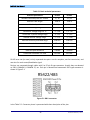
Devices are connected through cables with 9 or 25 pin D type connectors. Usually they are denoted
as DB-9, CANNON 9, CANNON 25, etc. Each pin is denoted and numerated. DB-9 type connector is
shown in Figure 5-1.
Figure 5-1 DB-9 connector
In the Table 5-2. Connector pinout is presented with short description of the pins.
47
© RAFA Solutions, 2014
InPEduS User Manual
Table 5-2 Connector pin outs
Contact
1
2
3
4
5
6
7
8
9
Abbreviation
TXDTXD+
RTSRTS+
GND
RXDRXD+
CTSCTS+
Direction
Out
Out
Out
Out
--In
In
In
In
Name
Transmitted Data
Transmitted Data
Request to Send
Request to Send
Ground
Received Data
Received Data
Clear to Send
Clear to Send
Data structure transmitted with RS485/422 protocol is identical to RS232 protocol. Data structure
with synchronization clock signal is given on Figure 5-2. Eight data bits, parity bit and stop bit are
used in this example. This structure is also denoted as 8Е1.
Figure 5-2 Time diagram
Parity Control
For parity check, two connected devices should calculate parity bits with the same algorithm (even or
odd parity). In case of even parity, data bits (including the parity bit) should have even number of
logical “1”. Odd parity corresponds to opposite case.
Parity check is the simplest way of error checking. It can detect error in one bit, but in case of errors
in 2 bits simultaneously this checking cannot detect errors. Besides, this control does not define
which bit has the error.
Other mechanisms of error checking are inclusion of start and stop bits into transmission, CRC, etc.
The signal line has two states: On and Off (logical 1 or 0). Line in waiting state is always on. When
device or computer wants to transfer data, they set the line in Off state, as a start bit setting.
Stop bit allows device or computer to process synchronization in case of failures. For example, noise
on line can hide start bit. Duration between start and stop bits is constant and depends on transfer
speed, number of data bits within message and parity bit existence. Stop bit is always on. If receiver
detects off state when stop bit should be present, error is detected.
In the frame stop signal can have 1 or 2 bits. 1 bit selection is more common.
48
© RAFA Solutions, 2014
InPEduS User Manual
Exercise №1. Data transmission in RS422/485 protocol.
The purpose of the exercise is a study of data transmission in RS422/485 protocol.
The data is being transmitted in 8-bit format. Parity bit should not be included in the data frame.
Frame should have 1 stop bit.
The program generates numbers to be sent automatically. These numbers are given in the “Numbers
to Send” field on the top of the window.
The purpose of this exercise as well as short instructions are provided on the right side of the
window.
Exercise Instructions
Write Data into corresponding template and click on the template to construct the frame to be sent.
After clicking selected template will appear in the “Data to Send” field. After the frame is complete
and correct states for the RS422/485 signals are set click the “Send” button.
In case of error within the frame or signals' states Warning Indicator will turn red. Click the “Clear”
button and assemble the frame once more.
If the frame is constructed correctly, it will appear in the “Sent Data” field after clicking “Send”
button.
Sent numbers can be checked by clicking “Check” button. If the numbers within the frame are
correct, the dialog box will appear with “Correct!” text, the dialog with “Incorrect!” text will appear in
opposite case. Clear “Sent Data” field in this case and repeat all steps.
The program gives also opportunity to create reports based on the exercise results in MS Word
format. Click “Report” button to create the report.
49
© RAFA Solutions, 2014
InPEduS User Manual
If the exercise is not finished after “Report” button is pressed corresponding dialog will appear and
the report will not be generated.
If the exercise is finished correctly, window will appear after pressing “Report” button to fill user's
name.
The report includes protocol name, exercise number and purpose, user's name, date, as well as the
image of constructed frame, depending on the purpose of the exercise. Save the file in any folder you
want.
50
© RAFA Solutions, 2014
InPEduS User Manual
Exercise №2. Data reception in RS422/485 protocol.
The purpose of the exercise is a study of data reception in RS422/485 protocol.
The data is being transmitted in 8-bit format. Parity bit is not included in the data frame. Frame has 1
stop bit.
The purpose of this exercise as well as short instructions are provided on the right side of the
window.
Exercise Instructions
In order to receive data from the receiver, data request should be sent. Request should be sent by
using appropriate signal states of RS422/485 protocol.
If the set states of the signals are correct received data frame will appear in the “Received Data
Frame” field. Click “Receive” button to move the frame to “Received Data” field and receive next
frame of the data.
In case of error within the signals' states Warning Indicator will turn red. Correct signal's states and
click the “Receive” button once more.
To check received data convert binary numbers to decimal, enter numbers and click “Check” button.
If the numbers within the frame are correct, the dialog box will appear with “Correct!” text, the
dialog with “Incorrect!” text will appear in opposite case.
The program gives also opportunity to create reports based on the exercise results in MS Word
format. Click “Report” button to create the report.
If the exercise is not finished after “Report” button is pressed corresponding dialog will appear and
the report will not be generated.
51
© RAFA Solutions, 2014
InPEduS User Manual
If the exercise is finished correctly, window will appear after pressing “Report” button to fill user's
name.
The report includes protocol name, exercise number and purpose, user's name, date, as well as the
image of constructed frame, depending on the purpose of the exercise. Save the file in any folder you
want.
52
© RAFA Solutions, 2014
InPEduS User Manual
6. Protocol Modbus
Modbus is communication protocol based on client-server architecture. It is widely used in IT to
organize connection between electrical devices. The protocol can be used to transfer data through
serial connection lines RS-485, RS-422, RS-232, as well as TCP/IP network (Modbus TCP). Modbus was
designed by Modicon Company. It was published in 1979 for the first time.
Modbus protocol has 2 modifications Modbus Plus and Modbus TCP. Modbus Plus is multi-master
protocol with cyclic marker transmission, and Modbus TCP is intended to be used in Ethernet and
Internet networks. Modbus protocol itself has two transmission modes: RTU (Remote Terminal Unit)
and ASCII. Standard considers that RTU mode should exist in Modbus protocol obligatorily and the
ASCII mode is optional.
The basic characteristic of the protocol is that there is only one master in the network. Modbus
allows to design industrial network from one master and up to 247 slaves. Only master may initiate
commands for remaining devices, which are slaves. The slave cannot start data transfer itself, or to
request data from other devices. Master can also broadcast a request addressed to all devices in the
network, in this case the response-message is not sent.
Transmission Modes
The transmission mode (Table 6-1) defines the structure of separate information blocks within the
message, which is used for data transmission. There are 2 transmission modes in Modbus system.
Both modes guarantee identical compatibility during connection with slaves. The mode is selected
depending on device used as Master Modbus. For each Modbus system only a single mode should be
used. Mode mixing is not allowed.
Table 6-1. ASCII and RTU mode characteristics
Characteristics
Coding system
Number of bits per symbol
Start bits
Data bits (LSB)
Parity
Stop bits
Checksum
ASCII (7-bit)
ASCII symbols 0-9. A-F are used
RTU (8-bit)
8-bit binary system
1
7
On/Off
1 or 2
LRC (Longitudinal Redundancy
Check). LRC
1
8
On/Off
1 or 2
CRC (Cyclical Redundancy
Check). CRC_16
It is more comfortable to use ASCII symbols in debugging, so this mode is convenient for computers
which are programmed with high level languages. The RTU mode is more convenient for computers
which are programmed with machine level languages. In RTU mode data is transmitted as 8-bit
binary symbol. In ASCII mode each RTU symbol is first divided into two 4-bit segments (most
significant and least significant), is transformed into its hexadecimal equivalent and then is used for
53
© RAFA Solutions, 2014
InPEduS User Manual
message generation. ASCII mode uses two times more symbols than RTU mode. But the decoding
and data management is easier. The message symbols in RTU mode should be transmitted as
continuous stream, whereas in ASCII mode it is allowed 1 sec delay between two adjacent symbols.
Modbus TCP
Modbus TCP as well as TCP/IP is used for data transmission within Ethernet network. TCP ADU for
Modbus TCP has the following construction:
Transaction ID
Protocol ID
Packet Length
Slave’s address
Function code
Data
•
Transaction ID— 2 bytes, usually zeros.
•
Protocol ID — 2 bytes, zeros.
•
Packet length — two bytes, high and then low, the length of the subsequent packet segment.
•
Slave’s Address — Slave devices address, to which command is sent. Usually is ignored, if the
connection is with specified device.
There is no checksum field in Modbus TCP.
Modbus RTU
Modbus RTU messages are transmitted as frames, for each of which the beginning and the end are
known. The frame begins with delay of not less than 3.5 hexadecimal symbols (14 bits) duration.
Frame should be transmitted continuously. If a delay of more than 1.5 hexadecimal symbols (6 bits) is
found during transmission it is considered that the frame has an error and it should be declined by
receiver. This delay values should be strictly complied for speeds lower than 19200 bit/sec, however
for fast speeds it is recommended to use fixed delay values of 1.75ms and 750µs correspondingly.
In Modbus RTU protocol messages are transmitted as PDU (Protocol Data Unit) packets.
Function Code Data
However to transmit the packet through physical layers PDU is placed in another packet, which has
additional fields. This packet is called ADU (Application Data Unit). ADU format dependents on
connection line type.
The general structure of ADU is as follows (dependent on realization, some fields can be missing):
Slave address Function code Data Error detection block
Slave address is the address of the slave device, to which request is addressed. Slaves are responding
only to those requests which have their address. The response starts with slave address, which can
54
© RAFA Solutions, 2014
InPEduS User Manual
vary from 1 to 247. Address 0 is used for broadcast transmission it is received by every device.
Addresses 248-255 are reserved.
Function code is a one-byte field. It informs the slave what actions or what data are required by
master.
Data is the field with information, necessary for slave to take actions requested from master, or data
transmitted from slave to master as a response. The length and format of the field depends on
function number.
Error detection block (CRC) is the checksum for error checking in the frame. For sequential
RS232/RS485 networks the maximal size of ADU is 256 bytes, and for TCP networks 260 bytes.
In Modbus RTU protocol data is transmitted by bytes in LSB format with addition of control bits
(start, stop and parity bits).
In RTU mode default value for parity bit is 1, if the number of “1”-s within byte is odd, and 0, if the
number is even. This parity is called even parity, and the control method is called parity control.
Other type of parity control is odd parity, in this case, the parity bit is “1” if the number of logical “1”s
within byte is even.
Start bit
1(LSB) 2 3 4 5 6 7 8 Parity bit
Stop bit
If Parity control is not used second stop bit is used instead of parity bit.
Error control in Modbus RTU
During data transfer errors of 2 types can take place.
•
•
Errors connected with data corruption during transmission
Logical errors
Errors of first type are detected with symbol frames, parity control and CRC-16-IBM (polynomial
number 0xA001 is used).
In this case the least significant bit is transmitted first, opposite to address bytes and register value in
PDU.
In RTU mode message should start and end with silence intervals, with duration of not less than the
transmission time of 3.5 symbols with current speed in the network. Then device address is sent.
After last transmitted symbol there is a delay of not less than 3.5 symbols duration as well. The new
message can start after this interval.
Message frame is transmitted continuously. If the silence interval of more than 1.5 symbols length
takes place, the frame should be ignored from receiver device.
Intervals (for Serial Modbus RTU): in case of speed 9600 bit/sec and 11 bits within frame (start bit + 8
data bits + parity control bit + stop bit): 3.5 * 11 / 9600 = 0.00401041(6), more than 4ms; 1.5 * 11 /
9600 = 0,00171875, more than 1ms. For speeds more than 19200 bit/sec intervals of 1,75 and 0,75
мс are allowed correspondingly.
55
© RAFA Solutions, 2014
InPEduS User Manual
CRC-16 (Cyclic Redundancy Check)
Message (only data bits, without taking into consideration start/stop bits and parity bit) is considered
as a single binary number, in which MSB is transmitted first. The message is multiplied to X16 (is
shifted to left by 16 bits), and then is divided to polynomial Х16+Х15+Х2+1, expressed as binary
number (11000000000000101). The integer part of the expression is ignored, and the 16-bit
remainder (initialized with “1”s to avoid the case when the message consists of “0”s) is added to the
message as 2 bytes checksum. Received message then is divided to the same polynomial in the
receiver (Х16+Х15+Х2+1). If there are no errors, remainder from the division is 0. The receiver can
calculate the CRC and compare it to the received one. All arithmetic is done by module 2 (without
transmission).
Device, which is used to prepare data for transmission, sends the LSB bit of each symbol first. During
CRC calculation the first transmitted bit is defined as MSB of dividend. As the arithmetic is not using
transmission, it is convenient to consider MSB to be in the right. This means that the bit order during
calculations should be reversed. The polynomial MSB is ignored as it affects only on divider and not
on remainder. As a result we get 1010 0000 0000 0001 (А001Н). Note, that the reversing of the bit
order has no effect on interpretation or bit order of data bytes during CRC calculation.
Step by step procedure of CRC-16 calculation is given below:
1. Load 16-digit register with number FFFFH.
2. Perform XOR operation on first data byte and the most significant byte of the register.
3. Put the result in register
4. Shift one bit to right in the register.
5. If the bit shifted right is “1”, perform XOR operation on register and polynomial 1010 0000
0000 0001 (А001Н).
6. If the shifted bit is “0”, return to step 4.
7. Repeat steps 4 - 6 until 8 register shifts.
8. Perform XOR operation on next data byte and register.
9. Repeat steps 4-8 until XOR operation will be performed on all data bytes and register.
10. The value of register is 2 byte CRC and is added to the initial message in MSB format.
Modbus data-types and standard functions
Modbus specifies 4 data types:
•
Discrete Inputs - one bit type, available only for read.
•
Coils - one bit type, available for read and write
•
Input Registers - 16-bit signed or unsigned type, available only for read.
•
Holding Registers - 16-bit signed or unsigned type, available for read and write.
56
© RAFA Solutions, 2014
InPEduS User Manual
Data types of Modbus protocol are given in Table 6-2 :
Table 6-2. Modbus Data types
Data type
1 bit
1 bit
16-bit word
16-bit word
Discrete Inputs
Coils
Input Registers
Holding Registers
Access type
Only read
Read/write
Only read
Read/write
To read values of these data functions with codes 1—4 (0x01—0x04) are used:
•
1 (0x01) —Read Coil Status.
•
2 (0x02) —Read Discrete Inputs.
•
3 (0x03) —Read Holding Registers.
•
4 (0x04) —Read Input Registers.
Request consists of the address of first element in the table (which value should be read) and the
number of elements to read. Address and number of data are given with 16-bit numbers (MSB).
Requested data is transmitted within the response. Data byte quantity depends on the number of
requested elements. 1 byte is transmitted before data transfer, with the value of data byte number.
Following functions are used to write one value:
•
5 (0x05) —Force Single Coil
•
6 (0x06) —Preset Single Register.
Command consists of element address (2 bytes) and set value (2 bytes). If the command is performed
correctly, the slave returns request copy.
Following functions are used to write several values:
•
15 (0x0F) —Force Multiple Coils
•
16 (0x10) —Preset Multiple Registers.
Command consists of element address, the number of changing elements, number of transmitting
data bytes and set values. In the response slave transmits initial address and the number of changed
elements.
Logical errors
To inform about logical errors Modbus RTU provides opportunity for devices to send responses in
case of error situations. Set most significant command bit can serve as a sign of error existence
within message. An example is given in Table 6-3.
57
© RAFA Solutions, 2014
InPEduS User Manual
1. If the slave receives correct request and is able to perform it normally, it sends normal
response.
2. If the slave denies the values, it does not send any response. Master diagnoses the error by
time-out.
3. If the slave receives a request with detected error (parity, LRC, CRC), it does not send any
response. Master diagnoses the error by time-out.
4. If the slave receives the request, but is not able to process (access to not existing register), a
response with error data is sent.
Table 6-3. Response frame (Slave -> Master) in case of error in Modbus RTU
Transfer
direction
Request
(Master→Slave)
Response
(Slave→Master)
Function
code
Data (or error code)
CRC
0x01
0x77
0xDD
0xC7 0xA9
0x01
0xF7
0xEE
0xE6 0x7C
Slave address
If the slave receives request with correct address, but incorrect subsequent bytes (for instance, CRC
and so on), it should send the response informing master about error.
For this purpose, as a response 0x80 is added to the byte of function code, and the 3rd byte equals
0x02 – which is a standard signal showing error in received data in Modbus protocol.
Standard error codes
•
01 — the function code cannot be processed on slave.
•
02 — data address in the request is not available for current slave.
•
03 — value in data field is not allowed for current slave.
•
04 — unrecoverable error took place, when slave was trying to perform required actions.
•
05 — the slave has received the request and is processing it, but it takes a long time. This
response prevents master from generating time-out error.
•
06 — the slave is processing a command. Master should repeat message afterwards, when
the slave will be free.
•
07 — the slave is not able to perform program function, received in request. This code is used
in case of unsuccessful program request, with function codes 13 and 14. Master should
request diagnostic information or error information from slave.
•
08 — the slave tries to read extended memory, but detected parity error. Master should
repeat the request, but usually in these cases a repair is needed.
58
© RAFA Solutions, 2014
InPEduS User Manual
Exercise №1. Data transmission in Modbus protocol.
The purpose of the exercise is a study of data transmission in Modbus protocol.
The data is being transmitted in 8-bit format. Frame should include start and stop bits for each of the
bytes. Parity bit is not used.
The program generates numbers to be sent automatically. These numbers are given in the “Numbers
to Send” field on the top of the window. For data transmission Slave address and Function code
should be mentioned.
The purpose of this exercise as well as short instructions are provided on the right side of the
window.
Exercise Instructions
Write Data into corresponding template and click on the template to construct the frame to be sent.
After clicking selected template will appear in the “Data to Send” field. After the frame is complete
click the “Send” button.
In case of error within the frame Warning Indicator will turn red. Click the “Clear” button and
assemble the frame once more. You can send all the numbers within one frame or each number
within separate frames.
To calculate the CRC use calculator in the bottom of the window. Write down the polynomial in the
“CRC Polynomial” field. Fill the “Data” field, and click “Calculate CRC” button afterwards. Data and
CRC Polynomial should be entered in hexadecimal format without spaces.
Data for CRC High Byte and CRC Low Byte are also shown in hexadecimal format.
If the frame is constructed correctly, it will appear in the “Sent Data” field after clicking “Send”
button. Sent numbers can be checked by clicking “Check” button. If the numbers within the frame
59
© RAFA Solutions, 2014
InPEduS User Manual
are correct, the dialog box will appear with “Correct!” text, the dialog with “Incorrect!” text will
appear in opposite case. Clear “Data to Send” and “Sent Data” fields in this case and repeat all steps.
The program gives also opportunity to create reports based on the exercise results in MS Word
format. Click “Report” button to create the report.
If the exercise is not finished after “Report” button is pressed corresponding dialog will appear and
the report will not be generated.
If the exercise is finished correctly, window will appear after pressing “Report” button to fill user's
name.
The report includes protocol name, exercise number and purpose, user's name, date, as well as the
image of constructed frame, depending on the purpose of the exercise. Save the file in any folder you
want.
60
© RAFA Solutions, 2014
InPEduS User Manual
Exercise №2. Error detection in Modbus protocol.
The purpose of this exercise is to check received data and send error message in Modbus protocol.
Received data packet should be checked and in case of error, error message should be sent.
Frame should include start and stop bits for each of the bytes. Parity bit is not used.
Data frame which should be checked is shown in the field “Received Data”.
The purpose of this exercise as well as short instructions are provided on the right side of the
window.
Exercise Instructions
To check the frame, you should calculate the CRC code using calculator at the button of the window.
You should check if the calculated CRC is the same as in the frame. In case of error response frame
should be sent with error notification.
Click on the templates to construct the frame. After clicking, selected template will appear in the
“Data to Send” field. In case of error within the frame Warning Indicator will turn red. Click the
“Clear” button and assemble the frame once more.
After the frame is complete click the “Send” button, the frame will appear in the “Sent Data” field.
To calculate the CRC use calculator in the bottom of the window. Write down the polynomial in the
“CRC Polynomial” field. Fill the “Data” field, and click “Calculate CRC” button afterwards. Data and
CRC Polynomial should be entered in hexadecimal format without spaces.
The program gives also opportunity to create reports based on the exercise results in MS Word
format. Click “Report” button to create the report.
61
© RAFA Solutions, 2014
InPEduS User Manual
If the exercise is not finished after “Report” button is pressed corresponding dialog will appear and
the report will not be generated.
If the exercise is finished correctly, window will appear after pressing “Report” button to fill user's
name.
The report includes protocol name, exercise number and purpose, user's name, date, as well as the
image of constructed frame, depending on the purpose of the exercise. Save the file in any folder you
want.
62
© RAFA Solutions, 2014
InPEduS User Manual
7. Protocol GPIB
GPIB (General Purpose Interface Bus) is common purpose interface bus.
In the middle 1960s the company Hewlett Packard introduced Hewlett-Packard Interface Bus, HP-IB
as a multipurpose controller. In the 1970s the standard was updated to more common GPIB, which is
also known as standard IEEE-488. In the beginning of 1990s new specifications of the standard were
released, as well as the new specification for programming language SCPI, which helped to simplify
software development for measurement devices.
Software tools for GPIB bus are mostly being released by companies National Instruments and
Keithley Instruments, the group of enthusiasts “Linux Lab Project” is also working on this topic.
Characteristics
Each device on the bus has unique 5-bit primary address (from 0 to 30). To avoid conflicts addresses
should be different. Standard allows to connect to single 20 meter physical bus up to 15 devices.
It is possible to connect 3 different types of devices to the bus (Figure 7-1):
•
Listener
•
Talker
•
Controller
Figure 7-1 GPIB System
Listener is counting messages from the bus, and talker is sending messages to the bus. Only single
device can serve as a talker, whereas the number of listeners can be arbitrary. The controller
functions as an arbiter and defines which of the devices at the moment are talkers or listeners.
Several controllers can be connected to the bus simultaneously. In this case one of the controllers
(generally located on the GPIB interface card) is the responsible controller (Controller-in-Charge, CIC)
and delegates its functions to other controllers as required.
Bus signal lines are related to one of the following 3 classes: data lines, handshake lines and interface
control lines. 8 data lines are being used for command forwarding, the most significant bit (DIO8) is
63
© RAFA Solutions, 2014
InPEduS User Manual
ignored in most cases. Data lines are numerated from 1 to 8, and not from 0 to 7, as it is done in the
most of standards.
Handshake lines control data and command transfer and provide guaranteed reception of data by all
listeners at proper time.
Signal examples are brought below:
Data Valid is used by talker to notify listeners that information prepared by talker is displayed on
data lines and is ready to receive.
Not Ready for Data is used by listeners to inform talker that they are not ready to receive data. In
this case talker stops information transfer until all the listeners are ready to continue dialog. The
signal is realized in terms of “wired or” principle, which allows any listener to stop the transmission.
Not Data Accepted is used by listeners and informs talker that data is received by all addressers. If
this signal is inactive, the talker is sure that all the clients have read the data from bus and it can
transfer the next data byte. The handshaking procedure guarantees that data transfer speed within
the bus does not exceed the data processing speed of the slowest client.
Talker displays new data on the bus only after all the listeners are ready for receive.
5 lines of interface control inform the devices connected to the bus what actions to take, in which
mode to be and how to react on GPIB commands. The bus controller uses Attention line to inform
clients that the bus is transmitting commands instead of data.
Service Request is available to any device on the bus. Controller shifts the device mode, which has
sent this signal to talker and passes to it data transfer functions.
Interface Clear is used to initialize or reinitialize the bus.
Remote Enable shifts the mode of the device to execution of bus commands (and not control panel)
mode and vice versa.
End of Identify is used by talker to identify the end of the message. Controller displays this signal to
initiate parallel polls of devices connected to the bus.
IEEE-488 is 8-bit parallel bus containing 16 signal lines (8 bidirectional lines are used for data transfer,
3 for connection establishment, and 5 for bus control) and 8 wires for grounding.
All signal lines are using negative logic: the highest positive voltage is considered as logical “0”, and
the lowest negative voltage as logical “1”. Data lines (DIO) are numerated from 1 to 8.
5 interface control lines inform the devices connected to the bus what actions to take, what mode to
be in and how to react on GPIB commands.
64
© RAFA Solutions, 2014
InPEduS User Manual
Connectors
Figure 7-2 GPIB Connector
Connectors IEEE-488 (Figure 7-2)
Connector
№
1-4
5
IEEE
Name
Data
input/output
bit.
End-oridentify.
Destination
DIO1DIO4
EOI
6
Data valid.
DAV
7
Not ready for
data.
NRFD
8
Not data
accepted.
NDAC
9
Interface clear.
IFC
10
Service
request.
Attention.
SRQ
Shield
Data
input/output
bit.
Remote
enable.
SHIELD
DIO5DIO8
11
12
13-16
17
ATN
REN
Data lines
Interface management line - The EOI line has two purposes –
The Talker uses the EOI line to mark the end of a message
string, and the Controller uses the EOI line to tell devices to
identify their response in
a parallel poll.
Handshake line - Tells when the signals on the data lines are
stable (valid) and can be accepted safely by devices.
Handshake line – Indicates when a device is ready or not
ready to receive a message byte. The line is driven by all
devices when receiving commands, by Listeners when
receiving data messages, and by the Talker when enabling
the HS488 protocol.
Handshake line – Indicates when a device has or has not
accepted a message byte. The line is driven by all devices
when receiving commands, and by Listeners when receiving
data messages.
Interface management line - The System Controller drives
the IFC line to initialize the bus and become CIC.
Interface management line - Any device can drive the SRQ
line to asynchronously request service from the Controller.
Interface management line - The Controller drives ATN true
when it uses the data lines to send commands, and drives
ATN false when a Talker can send data messages.
shield
Data lines
Interface management line - The System Controller drives
the REN line, which is used to place devices in remote or
65
© RAFA Solutions, 2014
InPEduS User Manual
18
(wire twisted
with DAV)
(wire twisted
with NRFD)
(wire twisted
with NDAC)
(wire twisted
with IFC)
(wire twisted
with SRQ)
(wire twisted
with ATN)
Logic ground
19
20
21
22
23
24
GND
GND
GND
GND
GND
GND
local program mode.
Ground
Ground
Ground
Ground
Ground
Ground
“Logical Ground”
Commands
GPIB commands are being transferred through classical protocol IEEE-488.1. Standard gives format
for the commands which are being sent by device and format and coding for responses. Commands
usually are abbreviations of corresponding English expressions. A question mark is added to requestcommands. All mandatory commands are prefixed with “*”. Standard defines minimal amount of
opportunities which each device should be equipped with, including: receive and transmit data, send
request for service and react on signal “Clear Interface”. All commands and the most data use 7-bit
ASCII code, in which 8th bit is not used, or is used for parity.
Controller sends signals of 5 classes for getting information from devices connected to the bus and
for bus reconfiguration:
•
•
•
•
•
Uniline
Universal Multiline
Address Multiline
Talk Address Group Multiline
Listen Address Group Multiline
IEEE-488.2 Required and Optional Control Sequences
Description
Control Sequence
Send ATN-true commands
Set address to send data
Send ATN-false data
Send a program message
Set address to receive data
Receive ATN-false data
SEND COMMAND
SEND SETUP
SEND DATA BYTES
SEND
RECEIVE SETUP
RECEIVE RESPONSE MESSAGE
66
IEEE-488.2
Compliance
Mandatory
Mandatory
Mandatory
Mandatory
Mandatory
Mandatory
© RAFA Solutions, 2014
InPEduS User Manual
Receive a response message
Pulse IFC line
Place devices in DCAS
Place devices in local state
Place devices in remote state
Place devices in remote
with lockout state
Place devices in
local lockout state
Read IEEE 488.1 status byte
Send group execution
trigger(GET) message
Give control to another device
Conduct a parallel poll
Configure device’s parallel poll
Responses
Disable device’s parallel poll
capability
RECEIVE
SEND IFC
DEVICE CLEAR
ENABLE LOCAL CONTROLS
ENABLE REMOTE
Mandatory
Mandatory
Mandatory
Mandatory
Mandatory
SET RWLS
Mandatory
SEND LLO
Mandatory
READ STATUS BYTE
Mandatory
TRIGGER
Mandatory
PASS CONTROL
PERFORM PARALLEL POLL
Optional
Optional
PARALLEL POLL CONFIGURE
Optional
PARALLEL POLL UNCONFIGURE Optional
Second component of the command system is SCPI (Standard Commands for Programming
Instruments), which was accepted in 1990. SCPI defines standard rules for keyword abbreviation,
which should be used as commands. Keywords can be used either in long (for example, MEASure) or
in short (MEAS - measure) writing forms. Commands in SCPI format are prefixed with colon.
Command arguments are separated by comas. SCPI standard operates with programming instrument
model. Functional components of this model include measurement system (subsystems “Input”,
“Sensor” and “Calculator”), signal generation system (subsystems “Calculator”, “Source” and
“Output”) and subsystems “Format”, “Display”, “Memory” and “Trigger”.
488.2 Controller protocols
Protocols are high-level routines that combine a number of control sequences to perform common
test system operations. IEEE 488.2 defines two required protocols and six optional protocols, as
shown in Table 2. These protocols reduce development time because they combine several
commands to execute the most common operations required by any test system. The RESET protocol
ensures that the GPIB has been initialized and all devices have been cleared and set to a known state.
The ALLSPOLL protocol serial polls each device and returns the status byte of each device. The
PASSCTL and REQUESTCTL protocols pass control of the bus between a numbers of different devices.
The TESTSYS protocol instructs each device to run its own self-tests and report back to the Controller
whether it has a problem or is ready for operation. Perhaps the two most important protocols are
FINDLSTN and FINDRQS. The FINDLSTN protocol takes advantage of the IEEE 488.2 Controller
capability of monitoring bus lines to locate listening devices on the bus. The Controller implements
the FINDLSTN protocol by issuing a particular listen address and then monitoring the NDAC
67
© RAFA Solutions, 2014
InPEduS User Manual
handshake line to determine if a device exists at that address. The result of the FINDLSTN protocol is
a list of addresses for all the located devices. FINDLSTN is used at the start of an application program
to ensure proper system configuration and to provide a valid list of GPIB devices that can be used as
the input parameter to all other IEEE 488.2 protocols. The bus line monitoring capability of an IEEE
488.2 Controller is also useful to detect and diagnose problems within a test system. The FINDRQS
protocol is an efficient mechanism for locating and polling devices that are requesting service. It uses
the IEEE 488.2 Controller capability of sensing the FALSE to TRUE transition of the SRQ line. You
prioritize the input list of devices so that the more critical devices receive service first. If the
application program can jump to this protocol immediately upon the assertion of the SRQ line, you
increase program efficiency and throughput.
Keyword
RESET
ALLSPOLL
FINDRQS
PASSCTL
Name
Reset System
Find Device Requesting Service
Serial Poll All Devices
Pass Control
Compliance
Mandatory
Optional
Mandatory
Optional
REQUESTCTL Request Control
Optional
FIDLSTN
Find Listeners
Optional
TESTSYS
SETADD
Self-Test System
Set Address
Optional
68
Optional, but requires FINDLSTN
© RAFA Solutions, 2014
InPEduS User Manual
Exercise №1. Data transmission in GPIB protocol.
The purpose of the exercise is the study of data transmission in GPIB protocol.
The data is being transmitted in 8-bit format with given address.
In the top of the window is given the “Listener Address” of the receiver device. The program
automatically generates numbers to be sent, which are being displayed on “Numbers to Send” field
in the top of the window.
The purpose of this exercise as well as short instructions are provided on the right side of the
window.
Exercise Instructions
The listener address should be specified before starting data transfer. Convert address from decimal
format to binary and write down the binary code in “Data to Send” fields. Enable ATN and DAV
signals and click the “Send” button.
In case of error within the frame Warning Indicator will turn red. Click the “Clear” button and fill the
fields correctly.
To send the data disable the signal ATN, convert the data from decimal to binary format and write
down the binary code into “Data to Send” fields. You can send several numbers within single
transfer.
The transferred data will appear in the “Sent Data” field after clicking “Send” button. Sent numbers
can be checked by clicking “Check” button. If the numbers are correct, the dialog box will appear
with “Correct!” text, the dialog with “Incorrect!” text will appear in opposite case. Clear “Data to
Send” and “Sent Data” fields in this case and repeat all steps.
69
© RAFA Solutions, 2014
InPEduS User Manual
The program gives also opportunity to create reports based on the exercise results in MS Word
format. Click “Report” button to create the report.
If the exercise is not finished after “Report” button is pressed corresponding dialog will appear and
the report will not be generated.
If the exercise is finished correctly, window will appear after pressing “Report” button to fill user's
name.
The report includes protocol name, exercise number and purpose, user's name, date, as well as the
image of constructed frame, depending on the purpose of the exercise. Save the file in any folder you
want.
70
© RAFA Solutions, 2014
InPEduS User Manual
8. Protocol TCP
TCP (Transmission Control Protocol) is one of the main Internet protocols, intended for data
transmission management in TCP/IP networks and sub-networks. TCP is functioning as transport
layer protocol of OSI model.
TCP — is transport mechanism, which provides data stream, with preset connection. Protocol
guarantees the reliability of received data, performs second request for data, if data is lost and
eliminates duplicated data, if 2 copies of the same packet are received. Unlike UDP, TCP guarantees
that no data will be lost during transmission, and notifies the sender for transmission results. TCP
segment format is shown on Figure 8-1.
Figure 8-1 TCP segment format
Source port identifies client application, from which packets are sent.
Destination port identifies port, data is sent to.
Specified ports are attached to number of services that use TCP for transmission: 20/21 — FTP, 22 —
SSH, 23 — Telnet, 25 — SMTP, 80 — HTTP, 110 — POP3, 194 — IRC (Internet Relay Chat), 443 —
HTTPS (Secure HTTP), 1863 — MSN Messenger, 2000 — Cisco SCCP (VoIP), 3389 — RDP, 8080 —HTTP
Alternate port.
Sequence number has 2 options:
1. If SYN (synchronize) flag is set, this is ISN (Initial Sequence Number). First byte, which will be
transmitted in next packet will have sequence number equal to ISN + 1.
71
© RAFA Solutions, 2014
InPEduS User Manual
2. If SYN is not set, first data byte, which is transmitted in current packet has this sequence
number.
Acknowledgement number – this is next sequence number, which receiver is expecting. This is SN
(sequence number) + 1 of the last successfully received data byte. This field is used only if the ACK
flag is set to 1.
Offset This field specifies TCP header size in 4-byte words. Minimal size is 5 words and the maximal
15, which is 20 and 60 bytes correspondingly.
Reserved for future use (6 bits), should be set to 0. 5th and 6th bits of this field are already defined.
•
CWR (Congestion Window Reduced) flag is set by sender to indicate that a packet with ECE
(RFC 3168) flag set is received.
•
ECE (ECN-Echo) — identifies that specified node have ECN (explicit congestion notification)
option and to notify the sender about congestions in the network (RFC 3168).
Flags (Control bits). This field contains 6 1-bit flags.
•
URG Urgent pointer field is significant.
•
ACK Acknowledgement field is significant
•
PSH Push function. Asks to push the buffered data to receiver application.
•
RST Reset the connection.
•
SYN Synchronize sequence numbers.
•
FIN Final. FIN bit is used for connection termination.
Window Size. The value of this field defines number of data bites that the sender wants to receive.
Pseudo header. TCP-header does not provide information of source and destination addresses. This
means that even if the destination port is correct, it cannot guarantee that the message has found its
destination. As the purpose of TCP is reliable delivery of messages, this point has essential
importance. This problem could be solved in variety of ways. The simplest was to add address
information to TCP header, however, this would first bring to duplicated information, and second,
breaks the encapsulation principle of OSI model. This was the reason that developers decided to use
additional pseudo-header (Table 8-1 and Table 8-2):
Table 8-1. IPv4 TCP pseudo header
Bits
0-7
8-15
0-31
Source address
32-63
Destination address
64-95 0 0 0 0 0 0 0 0
Protocol
72
16-31
TCP length
© RAFA Solutions, 2014
InPEduS User Manual
Table 8-2 IPv6 pseudo header
Bits
0-23
0-96
Source address
128224
Destination address
256
TCP length
288
0
0
24-31
0 0 0 0 0 0 0 0 0 0 0 0 0 0 0 0 0 0 0 0 0 0
Next
header
•
Protocol/ Next header — has the value 6 (000000110 in binary format, 0x6 — in hexadecimal)
—TCP-protocol identifier.
•
TCP length —TCP length in bytes (TCP-header + data, pseudo header length is not
considered).
Pseudo header is not a part of TCP segment. It is used to calculate checksum before the message is
sent and after it is received.
Checksum. Checksum field is 16-bit complement of sum of all 16-bit words in header (including
pseudo header) and the data. Before checksum calculation 0 bits are added until the datagram length
is multiple of 16 bits (pseudo header and added 0s are not sent with the datagram). During checksum
calculation the Checksum field within UDP header is considered as 0. For checksum calculation
pseudo header and UDP-message are divided into words (1 word = 2 bytes = 16 bits).
When the message is received the receiver re-computes checksum, taking into consideration the
checksum field. If binary value of 16 “1”s is obtained in the result, the checksum is considered
descended. If the sum does not descend the datagram is being deleted.
An example of checksum computation is given below.
Message: 0x4500003044224000800600008c7c19acae241e2b.
First the sum of 16 bit words should be calculated:
4500 + 0030 + 4422 + 4000 + 8006 + 0000 + 8c7c + 19ac + ae24 + 1e2b = 2BBCF
BBD1 = 2 + BBCF = 1011101111010001
Checksum = complement (1011101111010001) = 0100010000101110 = 442E
Urgent pointer. 16-bit value of positive offset from the sequence number in current segment. This
field indicates the octet sequence number with which significant data ends. The field is used only if
the URG flag is set.
Options. Can be used in several situations to expand the protocol. Sometimes are used for testing.
73
© RAFA Solutions, 2014
InPEduS User Manual
Protocol operation
Unlike UDP, which can start data transmission immediately, TCP sets connections, which should be
created before data transfer. TCP connections can be divided into 3 states: connection
establishment, data transmission and connection termination.
•
Connection establishment TCP séance start, defined as handshaking, consists of 3 steps:
1. Client that tries to establish connection, sends a segment with sequence number and SYN flag
to server. Server receives segment, saves sequence number and tries to create socket for new
client service. In case of success server sends a segment with sequence number and ACK and
SYN flags to client, and goes to SYN-RECEIVED state. In case of failure server sends to client a
segment with RST flag.
2. If client receives a segment with SYN flag, it saves the sequence number and sends a segment
with ACK flag. If it receives also the ACK flag, client goes to ESTABLISED state. If the client
receives RST flag, it stops trying to connect. If the client does not receive response within 10
seconds, it repeats connection process once more.
3. If server receives a segment with ACK flag in SYN-RECEIVED state, it goes to ESTABLISHED
state. In opposite case it closes the socket after time out and goes to CLOSED state.
This process is called three way handshake, as despite possibility to establish connection within 4
segments (SYN to server, ACK to client, SYN to client, ACK to server), practically 3 segments are
used to save time.
•
Data transmission. During data transfer receiver uses the sequence number from received
segments to recover their initial order. Receiver notifies the transmitter the sequence number to
which it successfully received data, including this number to Acknowledgment number field. All
received data in confirmed sequence range are ignored. If the received segment contains larger
sequence number, then expected, data from the segment are buffered, but the sequence
number is not changed. If in future a segment with expected sequence number is received, data
order will be automatically recovered taking into account sequence numbers in segments.
To make sure that transmitter does not send data faster than the receiver can process it, TCP has
options to control stream. The field “Window size” is used for this purpose. In segments, sent
from receiver, current size of receiver buffer is indicated. Transmitter saves the window size and
sends data no more than indicated by receiver. If the receiver has sent the window size of 0, data
transmission in this direction stops, until receiver informs of larger window size.
There are cases, when the transmitter application can require to “push” some data sequence to
receiver without buffering. PSH flag is used for these purposes. If the PSH is set in received
segment, TCP realization sends all currently buffered data to receiver application. “Push” is
used, as an instant, in interactive applications.
•
Connection termination has 3 steps:
1. FIN and ACK flags are sent to server on connection termination.
74
© RAFA Solutions, 2014
InPEduS User Manual
2. ACK, FIN, response flags are sent from server to client, informing that connection is closed.
3. After reception of these flags client closes connection and sends to server ACK to confirm that
connection is closed.
75
© RAFA Solutions, 2014
InPEduS User Manual
Exercise №1. Data transmission in TCP protocol.
1. Connection Establishment in TCP protocol
The purpose of the exercise is a study of connection establishment in TCP protocol. Transmitter
should establish the connection with the receiver mentioning Source port and Destination port.
The purpose of this exercise as well as short instructions are provided on the right side of the
window.
Exercise Instructions
Write Data into corresponding template and click on the template to construct the frame to be sent.
All data except of flags should be entered in hexadecimal format. After clicking selected template will
appear in the “Data to Send” field. After the frame is complete click the “Send” button.
In case of error within the frame Warning Indicator will turn red. Click the “Clear” button and
assemble the frame once more.
If the frame is constructed correctly and connection is established appropriate message will appear.
Sent data will appear in the “Sent Data” field, and response frame will appear in the “Received Data”
field. In case of errors clear “Data to Send” and “Sent Data” fields and repeat all steps.
The program gives also opportunity to create reports based on the exercise results in MS Word
format. Click “Report” button to create the report.
If the exercise is not finished after “Report” button is pressed corresponding dialog will appear and
the report will not be generated.
76
© RAFA Solutions, 2014
InPEduS User Manual
If the exercise is finished correctly, window will appear after pressing “Report” button to fill user's
name.
The report includes protocol name, exercise number and purpose, user's name, date, as well as the
image of constructed frame, depending on the purpose of the exercise. Save the file in any folder you
want.
Click “Part 2” button to go to the second part of the exercise.
2. Data Transmission in TCP protocol
The purpose of the exercise is a study of data transmission in TCP protocol. Transmitter should send
data to the receiver mentioning Source port and Destination port.
The program generates numbers to be sent automatically. These decimal numbers are given in the
“Numbers to Send” field on the top of the window.
The purpose of this exercise as well as short instructions are provided on the right side of the
window.
Exercise Instructions
Write Data into corresponding template and click on the template to construct the frame to be sent.
All data except of flags should be entered in hexadecimal format. After clicking selected template will
appear in the “Data to Send” field. After the frame is complete click the “Send” button.
In case of error within the frame Warning Indicator will turn red. Click the “Clear” button and
assemble the frame once more.
77
© RAFA Solutions, 2014
InPEduS User Manual
If the frame is constructed correctly, it will appear in the “Sent Data” field after clicking “Send”
button, and response frame will appear in the “Received Data” field.
Sent numbers can be checked by clicking “Check” button. If the numbers within the frame are
correct, the dialog box will appear with “Correct!” text, the dialog with “Incorrect!” text will appear in
opposite case. Clear “Data to Send” and “Sent Data” fields in this case and repeat all steps.
The program gives also opportunity to create reports based on the exercise results in MS Word
format. Click “Report” button to create the report.
If the exercise is not finished after “Report” button is pressed corresponding dialog will appear and
the report will not be generated.
If the exercise is finished correctly, window will appear after pressing “Report” button to fill user's
name.
The report includes protocol name, exercise number and purpose, user's name, date, as well as the
image of constructed frame, depending on the purpose of the exercise. Save the file in any folder you
want.
Click “Part 3” button to go to the third part of the exercise.
3. Connection Termination in TCP protocol
The purpose of the exercise is a study of connection termination in TCP protocol. Transmitter should
terminate the connection with the receiver mentioning Source port and Destination port.
The purpose of this exercise as well as short instructions are provided on the right side of the
window.
78
© RAFA Solutions, 2014
InPEduS User Manual
Exercise Instructions
Write Data into corresponding template and click on the template to construct the frame to be sent.
All data except of flags should be entered in hexadecimal format. After clicking selected template will
appear in the “Data to Send” field. After the frame is complete click the “Send” button.
In case of error within the frame Warning Indicator will turn red. Click the “Clear” button and
assemble the frame once more.
If the frame is constructed correctly, it will appear in the “Sent Data” field after clicking “Send”
button, and response frame will appear in the “Received Data” field.
If the frame is constructed correctly and connection is established appropriate message will appear.
In case of errors clear “Data to Send” and “Sent Data” fields and repeat all steps.
The program gives also opportunity to create reports based on the exercise results in MS Word
format. Click “Report” button to create the report.
If the exercise is not finished after “Report” button is pressed corresponding dialog will appear and
the report will not be generated.
If the exercise is finished correctly, window will appear after pressing “Report” button to fill user's
name.
The report includes protocol name, exercise number and purpose, user's name, date, as well as the
image of constructed frame, depending on the purpose of the exercise. Save the file in any folder you
want.
79
© RAFA Solutions, 2014
InPEduS User Manual
Exercise №2. Data checking in TCP protocol.
The purpose of the exercise is data checking and error detection in TCP protocol.
Received data is given in the top of the window. Received datagram should be checked and declined
in case of an error. If the packet does not contain any errors it should be accepted.
The purpose of this exercise as well as short instructions are provided on the right side of the
window.
Exercise Instructions
To check the received data checksum should be calculated for the packet, after which it should be
compared to the received checksum. For checksum calculation use the calculator in the right side of
the window. Data should be written in the hexadecimal format in “IP Checksum” and “Data” fields.
Click the “Calculate Checksum” button. The calculated code in hexadecimal format will be displayed
in the “Checksum field”.
If the received datagram is correct, frame will appear in the “Received Data” field after pressing
“Receive” button. In case of error within the frame click “Decline” button, and next datagram will
appear. If the “Receive” button is pressed when there is an error, the warning indicator will turn to
red.
Received numbers can also be checked. Click “Check” button after writing down the data into
“Received Data” field in decimal format separated by commas. If the numbers are correct, the dialog
box will appear with “Correct!” text, the dialog with “Incorrect!” text will appear in opposite case.
Clear fields in this case and repeat all steps.
The program gives also opportunity to create reports based on the exercise results in MS Word
format. Click “Report” button to create the report.
80
© RAFA Solutions, 2014
InPEduS User Manual
If the exercise is not finished after “Report” button is pressed corresponding dialog will appear and
the report will not be generated.
If the exercise is finished correctly, window will appear after pressing “Report” button to fill user's
name.
The report includes protocol name, exercise number and purpose, user's name, date, as well as the
image of constructed frame, depending on the purpose of the exercise. Save the file in any folder you
want.
81
© RAFA Solutions, 2014
InPEduS User Manual
9. Protocol UDP
UDP (User Datagram Protocol) protocol was created by David P. Ride in 1980 and was officially
defined in RFC 768. Protocol is designed to transferring of datagrams between computer processes,
which are connected through single network with frame commutation and it is one of the key
elements of Internet Protocol Suite (also known as TCP/IP). With UDP computer applications can
send datagrams (messages) to other hosts through IP-network without need of initial message to
install special transfer channels.
UDP uses a simple model for transmission and provides unsafe service. As a result datagrams can
linger, be lost, duplicated or be received not in order. UDP implies that error checking and correction
either is not necessary or should be implemented in applications. Time-sensitive applications
frequently use UDP, as it is more preferable to lose frames than to wait for lingering frames, which
can be impossible in real time systems.
UDP is a stateless protocol which is also useful for servers, which are responsible for small requests
from big amount of clients, for instance streaming multimedia applications (IPTV, VoIP and most
online games).
Service Ports
UDP-applications use datagram sockets to apply connections between hosts. Application binds the
socket to its end point of data transmission, which is combination of IP address and service port. Port
is software structure defined by port ID with 16-bit integer value (from 0 to 65535). 0 port is
reserved, although it is a valid value for source port in the case if the sender does not wait for
response messages.
IANA (Internet Assigned Numbers Authority) has separated 3 groups of port IDs.
•
•
•
Ports with numbers from 0 to 1023 are used for usual, well-known services.
Port numbers from 1024 to 49151 are used for registered IANA services.
Ports from 49152 to 65535 – are dynamic ports and can be used for any purposes, as officially
they are not designed for any specified service.
A number of ports is registered for standard purposes. Example is given in Table 9-1.
Table 9-1.
Port ID
Designation
Purpose
1397
Audio-activmail
Active voice mail
1398
Video-activmail
Active video-mail
5002
RFE
Radio-Ethernet
6000-6063
X11
X Window System
7008
AFS3-update
Server-server actualization
82
© RAFA Solutions, 2014
InPEduS User Manual
Packet structure
UDP does not give any guarantee for message delivery for high level protocol and does not save
states of sent messages. This is the reason that UDP is also called Unreliable Datagram Protocol.
UDP provides multichannel transfer and header integrity and essential data checking. The UDP
datagram format is given in Figure 9-1.
15 16
0
31
UDP Source port
UDP Destination port
UDP message length
Checksum
Data
…….
Figure 9-1 UDP datagram format
UDP header consists of 4 fields, each of 2 byte length (16 bits). Two of these fields are optional if
using IPv4, whereas in IPv6 only source port is optional.
•
Source Port, 16 bits. This field, if needed (for instance the transmitter is waiting for a
response), has the port ID from which the data packet was sent. If the field is not used it is
filled with 0s.
•
Destination Port, 16 bits. Computer port, to which data was sent.
•
Length, 16 bits. Length (in bytes) of the current datagram, including header and data. The
minimal length is 8 bytes (the length of the header). Maximal length of the packet is 65535 (8
bytes for the header and 65527 bytes for data). For IPv4 actual limit of the data length is
65507 (besides 8 bytes for the header 20 bytes are used for IP header). Maximal value of the
field in case of IPv6 is 4,294,967,295 bytes (232 - 1), 8 bytes from which are used for the
header, and the remaining for the data.
•
Checksum, 16 bits. Checksum of the UDP packet is bitwise complement of 16-bit words 16-bit
sum (similar to TCP).
Checksum calculation
Before checksum calculation 0 bits are added until the datagram length is multiple of 16 bits (pseudo
header and added 0s are not sent with the datagram). During checksum calculation the Checksum
field within UDP header is considered as 0. For checksum calculation pseudo header and UDPmessage are divided into words (1 word = 2 bytes = 16 bits).
83
© RAFA Solutions, 2014
InPEduS User Manual
After this all words are summed using one’s complement arithmetic. The sum is then one’s
complemented and the value is written in the checksum field.
0 value of checksum is reserved, and it means that datagram does not have checksum. If the
calculated checksum equals to 0, the field is filled with binary units.
When the message is received the receiver re-computes checksum, taking into consideration the
checksum field. If binary value of 16 “1”s is obtained in the result, the checksum is considered
descended. If the sum does not descend the datagram is being deleted.
An example of checksum computation is given below. The 16-bit words are: 0x398a, 0xf802, 0x14b2,
0xc281.
0x398a + 0xf802 = 0x1318c → 0x318d
0x318d + 0x14b2 = 0x0463f → 0x463f
0x463f + 0xc281 = 0x108c0 → 0x08c1
0x08c1 = 0000 1000 1100 0001 → 1111 0111 0011 1110 = 0xf73e — 0xffff − 0x08c1 = 0xf73e.
IPv4 Pseudo header
If UDP works on IPv4, checksum is calculated in terms of pseudo header, which gives some
information from IPv4 header. Pseudo header is not a real IPv4 header, which is used for IP-packet
transmission. Pseudo header for checksum calculation is given in Table 9-2.
Table 9-2
Bits
0
32
64
96
128
160+
0–7
8 – 15 16 – 23 24 – 31
Source Address
Destination Address
0-s
Protocol
UDP length
Source Port
Destination Port
Length
Checksum
Data
Source and destination addresses are taken from IPv4 header. For UDP the Protocol field value is 17.
UDP length field gives the length of UDP header and data.
Checksum calculation is optional for IPv4. If it is not used the value is set to 0.
84
© RAFA Solutions, 2014
InPEduS User Manual
IPv6 Pseudo header
If working on IPv6 the checksum is a mandatory field in UDP datagram. During checksum calculation
pseudo header, which imitates the real IPv6 header is also used (Table 9-3):
Table 9-3.
Bits
0
32
64
96
128
160
192
224
256
288
320
352
384+
0–7
8 – 15
16 – 23
Source Address
24 – 31
Destination Address
0s
Source Port
Length
UDP length
Next header
Destination Port
Checksum
Data
Source address is the same as in IPv6 header. Destination address is the final receiver, if there is no
Routing header in IPv6-packet, this will be the destination address from IPv6 header, in opposite
case, on the initial node this will be the value of the last element of the Routing header, and on the
receiver node this will be the destination header from IPv6 header. The value of Next Header is the
protocol value, which is 17 for UDP protocol. UDP length is the length of UDP header and the data.
85
© RAFA Solutions, 2014
InPEduS User Manual
Exercise №1. Data transmission in UDP protocol.
The purpose of the exercise is a study of data transmission in UDP protocol.
The data is being transmitted in hexadecimal format. All the templates should be filled with
hexadecimal numbers.
The program generates numbers to be sent automatically. These numbers are given in the “Numbers
to Send” field on the top of the window. 1 byte of information corresponds to each transmitting
number.
The purpose of this exercise as well as short instructions are provided on the right side of the
window.
Exercise Instructions
Write Data into corresponding templates and click on the templates to construct the frame to be
sent. After clicking, selected template will appear in the “Data to Send” field. After the frame is
complete click the “Send” button.
In case of error within the frame Warning Indicator will turn red. Click the “Clear” button and
assemble the frame once more. You can send all the numbers within one frame or each number
within separate frames.
To calculate the checksum use calculator in the right side of the window. Write down the the data in
hexadecimal format in the fields “IP Checksum” and “Data” without spaces. Fill the “Data” field, and
click “Calculate Checksum” button afterwards.
If the frame is constructed correctly, it will appear in the “Sent Data” field after clicking “Send”
button.
86
© RAFA Solutions, 2014
InPEduS User Manual
Sent numbers can be checked by clicking “Check” button. If the numbers within the frame are
correct, the dialog box will appear with “Correct!” text, the dialog with “Incorrect!” text will appear in
opposite case. Clear “Sent Data” field in this case and repeat all steps.
The program gives also opportunity to create reports based on the exercise results in MS Word
format. Click “Report” button to create the report.
If the exercise is not finished after “Report” button is pressed corresponding dialog will appear and
the report will not be generated.
If the exercise is finished correctly, window will appear after pressing “Report” button to fill user's
name.
The report includes protocol name, exercise number and purpose, user's name, date, as well as the
image of constructed frame, depending on the purpose of the exercise. Save the file in any folder you
want.
87
© RAFA Solutions, 2014
InPEduS User Manual
Exercise №2. Data checking in UDP protocol.
The purpose of the exercise is data checking and error detection in UDP protocol.
Received data is given in the top of the window. Received datagram should be checked and declined
in case of an error. If the packet does not contain any errors it should be accepted.
The purpose of this exercise as well as short instructions are provided on the right side of the
window.
Exercise Instructions
To check the received data checksum should be calculated for the packet, after which it should be
compared to the received checksum. For checksum calculation use the calculator in the right side of
the window. Data should be written in the hexadecimal format in “IP Checksum” and “Data” fields.
Click the “Calculate Checksum” button. The calculated code in hexadecimal format will be displayed
in the “Checksum field”.
If the received datagram is correct, frame will appear in the “Received Data” field after pressing
“Receive” button. In case of error within the frame click “Decline” button, and next datagram will
appear. If the “Receive” button is pressed when there is an error, the warning indicator will turn to
red.
Received numbers can also be checked. Click “Check” button after writing down the data into
“Received Data” field in decimal format separated by commas. If the numbers are correct, the dialog
box will appear with “Correct!” text, the dialog with “Incorrect!” text will appear in opposite case.
Clear fields in this case and repeat all steps.
The program gives also opportunity to create reports based on the exercise results in MS Word
format. Click “Report” button to create the report.
88
© RAFA Solutions, 2014
InPEduS User Manual
If the exercise is not finished after “Report” button is pressed corresponding dialog will appear and
the report will not be generated.
If the exercise is finished correctly, window will appear after pressing “Report” button to fill user's
name.
The report includes protocol name, exercise number and purpose, user's name, date, as well as the
image of constructed frame, depending on the purpose of the exercise. Save the file in any folder you
want.
89
© RAFA Solutions, 2014