1
USB9501 Series
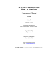
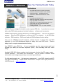
USB9501-14 DAQ Kits
See Your Testing Results Today
Applications
Use USB DAQ module to measurement data
Collection measurement data to make analysis
Waveform display, analysis and record
Waveform or data reports are easy to create
Features
Compatible with Windows O/S
USB bus configuration is easy to hand carry and use
Plug & play DAQ record software
Multifunction I/O for data measurement and record
Quick install with plug & play USB interface
DAQ development board
8 Analog channels, 12;14 or 16bit resolution
USB9501 Series is design for student or junior engineer DAQ kits。 It provides low cost and
high quality DAQ testing equipment includes hardware, software and accessories。
USB9501 help beginner learning DAQ theory and DAQ application。 User can use example
program, library and DAQ hardware to running on the PC or notebook, do the DAQ data
collection、DAQ recording、DAQ control and verify DAQ software function testing。
User can use USB9501 powerful hardware、software function to design their own DAQ
application or use DAQ development board to design their own DAQ circuit。 Reduce
design time for complex measurement and testing。
Use USB9501 series SAQ kits, let you immediately see the measurement result and
increase your ability for the data acquisition (DAQ) 、 DAQ recording and DAQ circuit
design。
Handheld USB DAQ device provide virtual instruments function like DC power supply,
function generator , multi-meter and oscilloscope 。 Let you handle 4 different virtual
instruments control design way and easy convenient operation style。
For high speed sample rate, high accuracy measurement, more DAQ channels and A/D
D/A signal compatibility, Please check measurement computer other high performance
USB DAQ device。 www.mccdaq.com
1
Bentech Computer Corp.
FAX: (886)02-26958911
7F-3, NO.23, LANE 169, KANG-NING ST., HIS-CHIH, TAIPEI HSIEN, TAIWAN, R.O.C.
TEL.:(886)02-26958906
Web Site www.bentech-taiwan.com
USB9501 Series
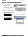
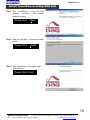
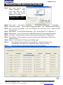
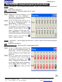
Install USB9501-12 DAQ module device driver
Step1: R u n S e t u p . e xe o n t h e C D - R O M
directory \SoftWIRE,follow the install
procedures on the window。
Step2: Put USB connect cable one site to your
USB DAQ module , another site
connect to your PC。 Now your PC will
auto-detect your USB device。
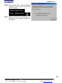
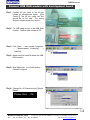
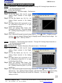
Step3: Click〔Start〕→ then choose〔Programs〕
→〔Me a su re m e n t Co m p u t in g 〕→
〔InstaCal〕,Now the InstCal will
appear following window, That is mean
your PC is detect your USB DAQ
module。
Please Click 〔Ok〕
Step4: After you press click〔OK〕button,It will
list all the hardware that PC detect。
Please Click 〔Ok〕
2
Bentech Computer Corp.
FAX: (886)02-26958911
7F-3, NO.23, LANE 169, KANG-NING ST., HIS-CHIH, TAIPEI HSIEN, TAIWAN, R.O.C.
TEL.:(886)02-26958906
Web Site www.bentech-taiwan.com
USB9501 Series
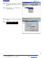
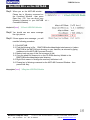
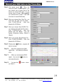
Step5: After you click〔OK〕button,InstCal will
put USB DAQ Module device driver to
the PC。
Step6: Now Right-click your DAQ module,
Choose Configure。
Step7: Change No. of Channels to be 8 Single
Ended
Step8:
Please Click 〔Ok〕
3
Bentech Computer Corp.
7F-3, NO.23, LANE 169, KANG-NING ST., HIS-CHIH, TAIPEI HSIEN, TAIWAN, R.O.C.
FAX: (886)02-26958911 TEL.:(886)02-26958906
Web Site www.bentech-taiwan.com
USB9501 Series
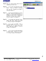
Step9: Now you need choose what kind of
software you want to use。
Step10:
If you need use Microsoft Visual
Basic、 C/C++ or Delphi to develop
your own API。Please go to page 5
then go to page 14。
Step11:
If you need immediately to see the
waveform,Please use NI LabView,to
design your own Graphic Programming
interface。Please go to page 7,
then go to page 14 and page 20。
Step12:
If you need use Microsoft Visual
Studio .NET 2003。Please go to page
8,then go to page 14 and page 23。
Step13:
If you need use EXCEL,TXT or
BITMAP FILE to record your DAQ
data。Please go to page 10,then go
to page 14 and page 18。
Step14:
If you need use MATLAB R2006a
or latest version 。Please go to page
15,then go to page 14 and page 15。
4
Bentech Computer Corp.
7F-3, NO.23, LANE 169, KANG-NING ST., HIS-CHIH, TAIPEI HSIEN, TAIWAN, R.O.C.
FAX: (886)02-26958911 TEL.:(886)02-26958906
Web Site www.bentech-taiwan.com
USB9501 Series
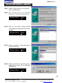
Install UNIVERSAL LIBRARY
Step1: Please install Microsoft Visual Basic,
C/C++ or Delphi first。
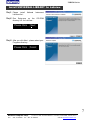
Step2: R u n S e t u p . e xe o n t h e C D - R O M
directory \Unilib\Product\disk1。
Please Click 〔Next〕
Step3: After you click Next , Please choose
your program development environment
support。
Please Click 〔Next〕
Step4: After you click Next,please select your
Programs directory。
Please Click 〔Next〕
Step5: After you click Next,there will appear a
window let you choose if you need read
README file。
Please Click 〔Yes〕
5
Bentech Computer Corp.
7F-3, NO.23, LANE 169, KANG-NING ST., HIS-CHIH, TAIPEI HSIEN, TAIWAN, R.O.C.
FAX: (886)02-26958911 TEL.:(886)02-26958906
Web Site www.bentech-taiwan.com
USB9501 Series
Step6: After you click Next,There will appear
a window let you choose if you need
restart computer。
Please Select Yes
Then,Please Click 〔OK〕
Step7: Right-click Start then click Explorer, you
can find out your example program In
the C:\MCC。
6
Bentech Computer Corp.
7F-3, NO.23, LANE 169, KANG-NING ST., HIS-CHIH, TAIPEI HSIEN, TAIWAN, R.O.C.
FAX: (886)02-26958911 TEL.:(886)02-26958906
Web Site www.bentech-taiwan.com
USB9501 Series
Install UNIVERSAL LIBRARY for Labview
Step1: Please
install
LabView first。
National
Step2: Run
Setup.exe on the
directory \UL for LabView。
Instrument
CD-ROM
Please Click 〔Next〕
Step3: After you click Next,please select your
Programs directory。
Please Click 〔Finish〕
7
Bentech Computer Corp.
7F-3, NO.23, LANE 169, KANG-NING ST., HIS-CHIH, TAIPEI HSIEN, TAIWAN, R.O.C.
FAX: (886)02-26958911 TEL.:(886)02-26958906
Web Site www.bentech-taiwan.com
USB9501 Series
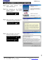
Install SoftWIRE for Microsoft .NET 2003
Step1: Please
install
Microsoft
Studio .NET 2003 first。
Visual
Step2: Run
setup.msi on the CD-ROM
directory \SoftWIRE 。 After appear
welcome window。
Please Click 〔Next〕
Step3: After you click Next,Please close your
virus protection program temporary。
Please Click 〔Next〕
Step4: After you click Next,The License
agreement window will appear。
Please Choose I accept
Please Click〔Next〕
8
Bentech Computer Corp.
7F-3, NO.23, LANE 169, KANG-NING ST., HIS-CHIH, TAIPEI HSIEN, TAIWAN, R.O.C.
FAX: (886)02-26958911 TEL.:(886)02-26958906
Web Site www.bentech-taiwan.com
USB9501 Series
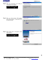
Step5: After you click Next,the ready to
install window will appear。
Please Click Install
Step6: After you click Install,Will appear
install status window,Please don’t click
the cancel button。
Step7: After Install finish,will appear install
finish window。
Please Click Finish
9
Bentech Computer Corp.
7F-3, NO.23, LANE 169, KANG-NING ST., HIS-CHIH, TAIPEI HSIEN, TAIWAN, R.O.C.
FAX: (886)02-26958911 TEL.:(886)02-26958906
Web Site www.bentech-taiwan.com
USB9501 Series
Install TracerDaq recording DAQ data
Step1: Run
TracerDaq.msi on the CD-ROM
directory \TracerDaq 。 After appear
welcome window。
Please Click 〔Next〕
Step2: After you click Next,Please click Install
button。
Please Click 〔Install〕
Step3: After install finish,will appear install
finish window。
Please Click Finish
10
Bentech Computer Corp.
7F-3, NO.23, LANE 169, KANG-NING ST., HIS-CHIH, TAIPEI HSIEN, TAIWAN, R.O.C.
FAX: (886)02-26958911 TEL.:(886)02-26958906
Web Site www.bentech-taiwan.com
USB9501 Series
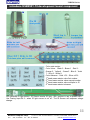
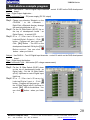
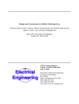
introduce USB9501-12 development board component
Color code resistor
Color Value: Black 0,Brown 1,Red 2,
Orange 3,Yellow 4,Green 5,Blue 6,Violet
7,Grey 8,White 9
Color tolerance:Gold ±
5%,Silver ±10%
st
1 band mean resistor value first number
2nd band mean resistor value second number
3rd band mean resistor value multiplier to 10
4th band mean resistor tolerance
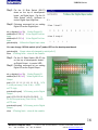
LED generate IR light source,IR Sensor receive IR light,200Ωresistor is use to protect LED,
Use Analog Input Bit 0,when IR light source is cut off,The IR Sensor will response voltage
change。
11
Bentech Computer Corp.
7F-3, NO.23, LANE 169, KANG-NING ST., HIS-CHIH, TAIPEI HSIEN, TAIWAN, R.O.C.
FAX: (886)02-26958911 TEL.:(886)02-26958906
Web Site www.bentech-taiwan.com
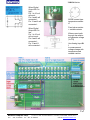
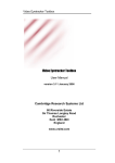
USB9501 Series
When Digital
Output Bit 0 is
high,
Pin 1 to 16 coil
will work,
Pin 4 and 8 will
connected,
Pin 13 and 9 will
connected。
When Digital
Output Bit 0 is
low,
Pin 1 to 16 coil
will not work,
Pin 4 and 6 will
connected,
Pin 13 and 11
will connected。
AD590 current type
temperature sensor
IC
Fixed value resistor
+ variable resistor
When current path
through the resistor
will generate voltage
(V=I*R)
Use Analog Input Bit
1
to measurement
voltage change with
temperature and
variable resistor
12
Bentech Computer Corp.
7F-3, NO.23, LANE 169, KANG-NING ST., HIS-CHIH, TAIPEI HSIEN, TAIWAN, R.O.C.
FAX: (886)02-26958911 TEL.:(886)02-26958906
Web Site www.bentech-taiwan.com
USB9501 Series
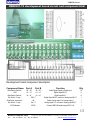
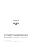
USB9501-12 development board circuit and component BOM
Development board component description
Component Name
Slide Switch (Vertical)
LED
Slide Switch (Vertical)
Dip Switch(8 way)
Slide Switch (horizontal)
Dip Switch(8 way)
40 PIN Header
Port A
Port B
S0~S7
S0~S7
L0~L7
L0~L7
s0~s7
s0~s7
SW 1-7
AS
Sw 1-7
IDC40
Function
Select Digital Output or Digital Input
Digital Output Bit 0-7
Digital Input Bit 0-7
Digital Output Bit 0-7 connect to Analog input Bit 0-7
Select Analog output 0 or Analog output 1
Analog output 0 0/1 connect to Analog input Bit 0-7
Connect USB DAQ module signal PIN 1~40
Q’ty
16
8
8
1
1
1
1
13
Bentech Computer Corp.
7F-3, NO.23, LANE 169, KANG-NING ST., HIS-CHIH, TAIPEI HSIEN, TAIWAN, R.O.C.
FAX: (886)02-26958911 TEL.:(886)02-26958906
Web Site www.bentech-taiwan.com
USB9501 Series
Connect USB DAQ module with development board
Step1: Connect 40 pin cable to the 40 pin
header on development board ,【Be
Careful 】 The 40 pin cable red line
should be on left side , The wrong
direction maybe cause short circuit。
Step2: Put USB cable one sit to the USB DAQ
module,Another side connect to PC。
Step3: Click〔Start〕→ then choose〔Programs〕
→ 〔 Measurement Computing 〕 →
〔InstaCal〕
Step4: Make sure that InstaCal detect the USB
DAQ module。
Step5: Now Right-click your DAQ module,
Choose Configure
Step6: Change No. of Channels to be 8 Single
Ended。
Please Click 〔Ok〕
14
Bentech Computer Corp.
7F-3, NO.23, LANE 169, KANG-NING ST., HIS-CHIH, TAIPEI HSIEN, TAIWAN, R.O.C.
FAX: (886)02-26958911 TEL.:(886)02-26958906
Web Site www.bentech-taiwan.com
USB9501 Series
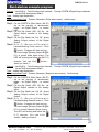
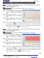
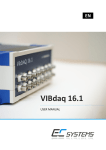
Run DAQ Kits on the MATLAB
Step1: When you on the MATLAB window,
Please key in following command on
the Command Window , then press
Enter Key。(PS. You can direct copy
following command to your MATLAB
Command Window)
daqhwinfo('mcc') %Check USB DAQ Module
Step2: You should can see same message
like right picture。
Step3: If there appear error message,you will
need do following procedure
3-1. Quit MATLAB.
3-2. Find the following ini file: $MATLAB\toolbox\daq\daq\private\mwmcc.ini (where
$MATLAB is the MATLAB root directory on your machine, as returned by typing
matlabroot at the MATLAB Command Prompt.)
3-3. Make a back-up copy of this file to mwmcc.ini.old.
3-4. Copy the attach file mwmcc.ini on the CD-ROM directory \Matlab to the
$MATLAB\toolbox\daq\daq\private\ directory
3-5. Right-Click mwmcc.ini change the read-only attributes is off。
3-6. Please key in following command on the MATLAB Command Window,then
press Enter Key。
daqregister('mcc') %Register USB DAQ Module
15
Bentech Computer Corp.
7F-3, NO.23, LANE 169, KANG-NING ST., HIS-CHIH, TAIPEI HSIEN, TAIWAN, R.O.C.
FAX: (886)02-26958911 TEL.:(886)02-26958906
Web Site www.bentech-taiwan.com
USB9501 Series
Step1: Put the 16 Slide Switch (S0-S7)
down on the top of development
board,as Digital Input,Put the 16
Slide Switch (s0-s7) Up/Down to
control Digital Input High/Low。
Step2: Following command let you setting
Digital I/O as the Digital Input。
dio = digitalio('mcc',0); %Initial Digital I/O
addline(dio,0:7,0,'in') %Use Digital Port0 as
Input
addline(dio,0:7,1,'in') %Use Digital Port1 as
Input
getvalue(dio) %Show the Digital Input value
You can change 16 Slide switch (s0-s7) under LED on the development board。
getvalue(dio) %Input value will changed by switch(s0-s7)
clear %Testing finish,clear all the variable
Step1: Put the 16 Slide Switch (S0-S7) Up
on the top of development board,
as Digital Output,to control LED。
Step2: Following command let you setting
Digital I/O as the Digital Output。
dio = digitalio('mcc',0);
%Initial Digital I/O
addline(dio,0:15,'out') %Use Digital I/O as
Output
pval = [1 1 1 1 1 1 1 1 1 1 1 1 1 1 1 1]; %Fill
1 to the pval array (Total 16 bit),1/LED
on/TTL high
putvalue(dio,pval) %Put array pval to Digital
Output
pval = [0 0 0 0 0 0 0 0 0 0 0 0 0 0 0 0]; %
Fill 0 to the pval array (Total 16 bit),0/LED
off/TTL low
putvalue(dio,pval) %Put array pval to Digital
Output
clear %Testing finish,clear all the variable
16
Bentech Computer Corp.
7F-3, NO.23, LANE 169, KANG-NING ST., HIS-CHIH, TAIPEI HSIEN, TAIWAN, R.O.C.
FAX: (886)02-26958911 TEL.:(886)02-26958906
Web Site www.bentech-taiwan.com
USB9501 Series
Step1: Put the Dip Switch (SW 1-8) Off,
Avoid Analog Output connect to the
Digital Output。
Step2: Put the Dip Switch (sw 1-8) On,Let
Analog Output connect to the Analog
Input。
Step3: Put Slide Switch (AS) (horizontal) to
the left (A0),Switch Analog Output
as Analog Output bit 0。
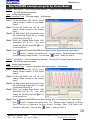
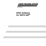
Step4: Following command let you control
Analog Output and Analog Input。
ao = analogoutput('mcc',0);
%Initial Analog Output
addchannel(ao,0) %Add Analog Output Channel 0
putdata(ao,4) %Set Analog Output Channel 0 Volt.=4V (Maximum Voltage is 4V)
start(ao);
%Start Analog Output Channel 0
ai = analoginput('mcc',0);
addchannel(ai,0);
start(ai);
%Initial Analog Input
%Add Analog Input Channel 0
%Start Analog Input Channel 0
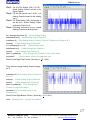
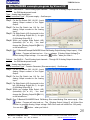
data1 = getdata(ai);
plot(data1)
%Put Analog Input Channel 0 value to the data1
%Put the data1 value to the waveform plot
Result is like Right-Top Picture. (Accuracy < + 0.1 Volt.)
Then we can change Analog Output Voltage
be 2V。
putdata(ao,2) %Set Analog Output Channel 0
Volt.=2
start(ao);
%Start Analog Output Channel 0
start(ai);
%Start Analog Input Channel 0
data1 = getdata(ai);
%Put Analog Input
Channel 0 value to the data1
plot(data1) %Put the data1 value to the
waveform plot
Result is like Right-Bottom Picture. (Accuracy < + 0.1 Volt.)
clear %Testing finish,clear all the variable
17
Bentech Computer Corp.
7F-3, NO.23, LANE 169, KANG-NING ST., HIS-CHIH, TAIPEI HSIEN, TAIWAN, R.O.C.
FAX: (886)02-26958911 TEL.:(886)02-26958906
Web Site www.bentech-taiwan.com
USB9501 Series
Record your DAQ data on the TracerDaq
Step1: First
need confirm your
display resolution , need
more than 1024 by 768
pixels , after finish setting
please click OK bottom!
Please Click 〔Ok〕
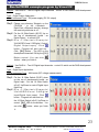
Step2: Click〔Start〕→ then choose〔Programs〕→〔Measurement Computing〕→〔TracerDaq〕
Step3: Configuration Name :You can define Configuration Name,Like:USB DAQ Module setting1
Step4: Plot:You can only choose 1 Plot Click Enabled,You can chose 8 Plot,Record 8 DAQ
channel signal
Step5: Signal Name:You can define Signal Name,Like:Analog Input Ch. 0 or Digital Ch. 0
Step6: Device Name:You must choose your USB DAQ module (Can not accept blank space)
Step7: Input Type:Please choose you want to measurement Analog Input or Digital Input
Step8: Input Channel:Please choose you want to measurement Analog Input or Digital Input
channel number
Step9: Range:Use to define your Analog input voltage range
Step10:
After Setting Please remember click Save Button,Next time when you use
TracerDaq you can select your configuration name, recall your setting。
Step11:
After you save your configuration name you can click OK Button。
18
Bentech Computer Corp.
7F-3, NO.23, LANE 169, KANG-NING ST., HIS-CHIH, TAIPEI HSIEN, TAIWAN, R.O.C.
FAX: (886)02-26958911 TEL.:(886)02-26958906
Web Site www.bentech-taiwan.com
USB9501 Series
Record your DAQ data on the TracerDaq
Step5: First please press
, When the
“save file option” window appear,you
can choose one of three kind of file
format for record DAQ data。Or you
choose three of them。(Be careful)(If
you choose three of them,It will take
more time to record DAQ data)
Step6: When you choose Save Text File,you
need give file path and file name ,
(Like C:\20071215.txt) , After that
please click OK Button。
Step7: When you choose Save EXCEL File,
you need give file path and file name,
(Like C:\20071215.xls) , After that
please click OK Button 。 (you can
bypass Worksheet setting,default is
Sheet1)
Step8: When you choose Save Bitmap File,
(Like C:\20071215.BMP) , After that
please click OK Button。
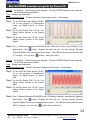
Step9: Please press
Button,program will
start to running。
Step10:
Each Plot measurement DAQ
signal data, will display by different
color。
Step11:
When you measurement DAQ
signal,You can click
save waveform plot。
Step12:
You can click
you finish it。
button to
button,when
19
Bentech Computer Corp.
7F-3, NO.23, LANE 169, KANG-NING ST., HIS-CHIH, TAIPEI HSIEN, TAIWAN, R.O.C.
FAX: (886)02-26958911 TEL.:(886)02-26958906
Web Site www.bentech-taiwan.com
USB9501 Series
Run Labview example program
Subject:Use DAQ kit,Test 16 Digital Output channels,control 16 LED on the DAQ development
board。
Type:Digital Output Application。
Virtual Instrument Type:DC power supply (DC 5V output)
Step1: Please copy directory \Bentech on the
CD-ROM , to the c:\Bentech ,
Right-Click c:\Bentech directory change
the read-only attributes is off。
Step2: Put the 16 Slide Switch (S0-S7) Up on
the top of development board , as
Digital Output,to control LED。
Step3: R u n C : \ B e n t e c h \ E x a m p l e \
Labview\Digital Output.vi,Click
button,Program will start and run。
Click 【Bit】Button ,The LED on the
development board will ON by the【Bit】
Button control。You can click
button,when you finish it。
Subject:Use DAQ kit,Test 16 Digital Input channels,control 16 switch on the DAQ development
board。
Type:Digital Input Application。
Virtual Instrument Type:Multi-meter (DC voltage measurement)
Step1: Put the 16 Slide Switch (S0-S7) down
on the top of development board,as
Digital Input,Put the 16 Slide Switch
(s0-s7) Up/Down to control Digital Input
High/Low。
Step2: R u n C : \ B e n t e c h \ E x a m p l e \
Labview\Digital Input.vi,Click
button,Program will start and run。Put
the 16 Slide Switch (s0-s7) Up/Down to
control 【Bit】 LED on the window。You
can click
it。
button,when you finish
20
Bentech Computer Corp.
7F-3, NO.23, LANE 169, KANG-NING ST., HIS-CHIH, TAIPEI HSIEN, TAIWAN, R.O.C.
FAX: (886)02-26958911 TEL.:(886)02-26958906
Web Site www.bentech-taiwan.com
USB9501 Series
Run Labview example program
Subject:Use DAQ kit,Test 8 Analog Input channels,Through PORTB 8 Digital Output channels
on the DAQ development board。
Type:Analog Input Application。
Virtual Instrument Type:Function Generator (Pulse wave output),Oscilloscope。
Step1: Put the PORTB 8 Slide Switch (S0-S7)
Up on the top-right of development
board , as Digital Output , to control
LED。
Step2: Put the Dip Switch (SW 1-8) On,Let
Digital Output connect to the Analog
Input。
Step3: Put the Dip Switch (sw 1-8) Off,Avoid
Analog Output connect to the Digital
Output。
Step4: R u n C : \ B e n t e c h \ E x a m p l e \
Labview\Analog Pulse wave.vi,Click
button,Program will start and run。
You can change【Analog Output Bit】(Bit
0-7) to control pulse wave output。The
LED will blinking and follow the (Bit 0-7)
change。You can click
when you finish it。
button,
Subject:Use DAQ kit,Test 8 Analog Input channels,Through PORTB 8 Digital Output channels
on the DAQ development board。
Type:Analog Input Application。
Virtual Instrument Type:Function Generator (Sawtooth wave output),Oscilloscope。
Step1: Put the PORTB 8 Slide Switch (S0-S7)
Up on the top-right of development
board , as Digital Output , to control
LED。
Step2: Put the Dip Switch (SW 1-8) On,Let
Digital Output connect to the Analog
Input。
Step3: Put the Dip Switch (sw 1-8) Off,Avoid
Analog Output connect to the Digital
Output。
Step4: R u n C : \ B e n t e c h \ E x a m p l e \
Labview\Analog Sawtooth wave.vi,Click
button,Program will start and run。
You can change【Analog Output Bit】(Bit
0-7) to control Sawtooth Wave output。
The LED will blinking and follow the (Bit
0-7) change。You can click
button,when you finish it。
21
Bentech Computer Corp.
7F-3, NO.23, LANE 169, KANG-NING ST., HIS-CHIH, TAIPEI HSIEN, TAIWAN, R.O.C.
FAX: (886)02-26958911 TEL.:(886)02-26958906
Web Site www.bentech-taiwan.com
USB9501 Series
Run Labview example program
Subject:Use DAQ kit,Test 8 Analog Input channels,Through AS 2 Analog Output channels on
the DAQ development board。
Type:Analog Input Application。
Virtual Instrument Type:DC power supply,Oscilloscope。
Step1: Put the Dip Switch (SW 1-8) Off,Avoid
Step2:
Step3:
Step4:
Step5:
Analog Output connect to the Digital
Output。
Put the Dip Switch (sw 1-8) On , Let
Analog Output connect to the Analog
Input。
Put Slide Switch (AS) (horizontal) to the
left (A0)(Analog Output Bit 0),or right
(A1)(Analog Output Bit 1)。
When you change Slide Switch (AS)
(horizontal) (A0 or A1),You must change
the 【Analog Output Bit】(Bit 0-1) on the
window too。
Run C:\Bentech\Example\Labview\Analog Output.vi,Click
button,Program will start
and run。You can change【Analog Output Voltage】to control Analog Output voltage。You
can click
button,when you finish it。
Subject:Use DAQ kit,Test 8 Analog Input channels,Through AS 2 Analog Output channels on
the DAQ development board。
Type:Analog Input Application。
Virtual Instrument Type:Function Generator (Sine wave output),Oscilloscope。
Step1: Put the Dip Switch (SW 1-8) Off,Avoid
Step2:
Step3:
Step4:
Step5:
Analog Output connect to the Digital
Output。
Put the Dip Switch (sw 1-8) On , Let
Analog Output connect to the Analog
Input。
Put Slide Switch (AS) (horizontal) to the
left (A0)(Analog Output Bit 0) ,or right
(A1)(Analog Output Bit 1)。
When you change Slide Switch (AS)
(horizontal) (A0 or A1),You must change
the 【Analog Output Bit】(Bit 0-1) on the
window too。
Run C:\Bentech\Example\Labview\Analog Sine wave.vi,Click
button,Program will
start and run。The 【Analog Output Voltage】 will follow Sine function to generate Analog
Output voltage. Each Sine wave will divide into 128 parts)。You can click
button,
when you finish it。
22
Bentech Computer Corp.
7F-3, NO.23, LANE 169, KANG-NING ST., HIS-CHIH, TAIPEI HSIEN, TAIWAN, R.O.C.
FAX: (886)02-26958911 TEL.:(886)02-26958906
Web Site www.bentech-taiwan.com
USB9501 Series
Run SoftWIRE example program by Visual C#
Subject:Use DAQ kit,Test 16 Digital Output channels,control 16 LED on the DAQ development
board。
Type:Digital Output Application。
Virtual Instrument Type:DC power supply (DC 5V output)
Step1: Please copy directory \Bentech on the
CD-ROM , to the c:\Bentech ,
Right-Click c:\Bentech directory change
the read-only attributes is off。
Step2: Put the 16 Slide Switch (S0-S7) Up on
the top of development board , as
Digital Output,to control LED。
Step3: R u n C : \ B e n t e c h \ E x a m p l e \
\SoftWIRE\Visual C#\Digital Output\
Digital Output.csproj,Click
button,Program will start and run。
Click 【Bit】Button ,The LED on the
development board will ON by the【Bit】
Button control。You can click
button,when you finish it。
Subject:Use DAQ kit,Test 16 Digital Input channels,control 16 switch on the DAQ development
board。
Type:Digital Input Application。
Virtual Instrument Type:Multi-meter (DC voltage measurement)
Step1: Put the 16 Slide Switch (S0-S7) down
on the top of development board,as
Digital Input,Put the 16 Slide Switch
(s0-s7) Up/Down to control Digital Input
High/Low。
Step2: R u n C : \ B e n t e c h \ E x a m p l e \
\SoftW IRE\Visual C#\Digital
Input\Digital Input.csproj,Click
button,Program will start and run。Put
the 16 Slide Switch (s0-s7) Up/Down to
control 【Bit】 LED on the window。You
can click
it。
button,when you finish
23
Bentech Computer Corp.
7F-3, NO.23, LANE 169, KANG-NING ST., HIS-CHIH, TAIPEI HSIEN, TAIWAN, R.O.C.
FAX: (886)02-26958911 TEL.:(886)02-26958906
Web Site www.bentech-taiwan.com
USB9501 Series
Run SoftWIRE example program by Visual C#
Subject:Use DAQ kit,Test 8 Analog Input channels,Through PORTB 8 Digital Output channels
on the DAQ development board。
Type:Analog Input Application。
Virtual Instrument Type:Function Generator (Pulse wave output),Oscilloscope。
Step1: Put the PORTB 8 Slide Switch (S0-S7)
Up on the top-right of development
board , as Digital Output , to control
LED。
Step2: Put the Dip Switch (SW 1-8) On,Let
Digital Output connect to the Analog
Input。
Step3: Put the Dip Switch (sw 1-8) Off,Avoid
Analog Output connect to the Digital
Output。
Step4: Run C:\Bentech\Example\SoftWIRE\Visual C#\Analog Pulse wave\Analog Pulse
wave.csproj,Click
button,Program will start and run。You can change 【Analog
Output Bit】(Bit 0-7) to control pulse wave output。The LED will blinking and follow the (Bit
0-7) change。You can click
button,when you finish it。
Subject:Use DAQ kit,Test 8 Analog Input channels,Through PORTB 8 Digital Output channels
on the DAQ development board。
Type:Analog Input Application。
Virtual Instrument Type:Function Generator (Sawtooth wave output),Oscilloscope。
Step1: Put the PORTB 8 Slide Switch (S0-S7)
Up on the top-right of development
board , as Digital Output , to control
LED。
Step2: Put the Dip Switch (SW 1-8) On,Let
Digital Output connect to the Analog
Input。
Step3: Put the Dip Switch (sw 1-8) Off,Avoid
Analog Output connect to the Digital
Output。
Step4: Run C:\Bentech\Example\SoftWIRE\Visual C#\Analog Sawtooth wave\Analog Sawtooth
wave.csproj,Click
button,Program will start and run。You can change 【Analog
Output Bit】(Bit 0-7) to control Sawtooth Wave output。The LED will blinking and follow the
(Bit 0-7) change。You can click
button when you finish it。
24
Bentech Computer Corp.
7F-3, NO.23, LANE 169, KANG-NING ST., HIS-CHIH, TAIPEI HSIEN, TAIWAN, R.O.C.
FAX: (886)02-26958911 TEL.:(886)02-26958906
Web Site www.bentech-taiwan.com
USB9501 Series
Run SoftWIRE example program by Visual C#
Subject:Use DAQ kit,Test 8 Analog Input channels,Through AS 2 Analog Output channels on
the DAQ development board。
Type:Analog Input Application。
Virtual Instrument Type:DC power supply,Oscilloscope。
Step1: Put the Dip Switch (SW 1-8) Off,Avoid
Analog Output connect to the Digital
Output。
Step2: Put the Dip Switch (sw 1-8) On,Let
Analog Output connect to the Analog
Input。
Step3: Put Slide Switch (AS) (horizontal) to the
left (A0)(Analog Output Bit 0),or right
(A1)(Analog Output Bit 1)。
Step4: When you change Slide Switch (AS)
(horizontal) (A0 or A1) , You must
change the【Analog Output Bit】(Bit 0-1)
on the window too。
Step5: Run C:\Bentech\Example\SoftWIRE\Visual C#\Analog Output\Analog Output.csproj,Click
button,Program will start and run。You can change 【Analog Output Voltage】to
control Analog Output voltage。You can click
button,when you finish it。
Subject:Use DAQ kit,Test 8 Analog Input channels,Through AS 2 Analog Output channels on
the DAQ development board。
Type:Analog Input Application。
Virtual Instrument Type:Function Generator (Sine wave output),Oscilloscope。
Step1: Put the Dip Switch (SW 1-8) Off,Avoid
Analog Output connect to the Digital
Output。
Step2: Put the Dip Switch (sw 1-8) On,Let
Analog Output connect to the Analog
Input。
Step3: Put Slide Switch (AS) (horizontal) to the
left (A0)(Analog Output Bit 0),or right
(A1)(Analog Output Bit 1)。
Step4: When you change Slide Switch (AS)
(horizontal) (A0 or A1) , You must
change the【Analog Output Bit】(Bit 0-1)
on the window too。
Step5: Run C:\Bentech\\SoftWIRE\Visual C#\Analog Sine wave\Analog Sine wave.csproj,Click
button,Program will start and run。The 【Analog Output Voltage】 will follow Sine
function to generate Analog Output voltage. Each Sine wave will divide into 128 parts)。
You can click
button,when you finish it。
25
Bentech Computer Corp.
7F-3, NO.23, LANE 169, KANG-NING ST., HIS-CHIH, TAIPEI HSIEN, TAIWAN, R.O.C.
FAX: (886)02-26958911 TEL.:(886)02-26958906
Web Site www.bentech-taiwan.com
USB9501 Series
Run SoftWIRE example program by Visual Basic
Subject:Use DAQ kit,Test 16 Digital Output channels,control 16 LED on the DAQ development
board。
Type:Digital Output Application。
Virtual Instrument Type:DC power supply (DC 5V output)
Step1: Please copy directory \Bentech on the
CD-ROM , to the c:\Bentech ,
Right-Click c:\Bentech directory change
the read-only attributes is off。
Step2: Put the 16 Slide Switch (S0-S7) Up on
the top of development board , as
Digital Output,to control LED。
Step3: R u n C : \ B e n t e c h \ E x a m p l e \
\SoftWIRE\Visual Basic\Digital Output\
Digital Output.vbproj ,Click
button,Program will start and run。
Click 【Bit】Button ,The LED on the
development board will ON by the【Bit】
Button control。You can click
button,when you finish it。
Subject:Use DAQ kit,Test 16 Digital Input channels,control 16 switch on the DAQ development
board。
Type:Digital Input Application。
Virtual Instrument Type:Multi-meter (DC voltage measurement)
Step1: Put the 16 Slide Switch (S0-S7) down
on the top of development board,as
Digital Input,Put the 16 Slide Switch
(s0-s7) Up/Down to control Digital Input
High/Low。
Step2: R u n C : \ B e n t e c h \ E x a m p l e \
\SoftW IRE\Visual Basic\Digital
Input\Digital Input.vbproj,Click
button,Program will start and run。Put
the 16 Slide Switch (s0-s7) Up/Down to
control 【Bit】 LED on the window。You
can click
it。
button,when you finish
26
Bentech Computer Corp.
7F-3, NO.23, LANE 169, KANG-NING ST., HIS-CHIH, TAIPEI HSIEN, TAIWAN, R.O.C.
FAX: (886)02-26958911 TEL.:(886)02-26958906
Web Site www.bentech-taiwan.com
USB9501 Series
Run SoftWIRE example program by Visual Basic
Subject:Use DAQ kit,Test 8 Analog Input channels,Through PORTB 8 Digital Output channels
on the DAQ development board。
Type:Analog Input Application。
Virtual Instrument Type:Function Generator (Pulse wave output),Oscilloscope。
Step1: Put the PORTB 8 Slide Switch (S0-S7)
Up on the top-right of development
board , as Digital Output , to control
LED。
Step2: Put the Dip Switch (SW 1-8) On,Let
Digital Output connect to the Analog
Input。
Step3: Put the Dip Switch (sw 1-8) Off,Avoid
Analog Output connect to the Digital
Output。
Step4: Run C:\Bentech\Example\SoftWIRE\Visual Basic\Analog Pulse wave\Analog Pulse
wave.vbproj,Click
button,Program will start and run。You can change 【Analog
Output Bit】(Bit 0-7) to control pulse wave output。The LED will blinking and follow the (Bit
0-7) change。You can click
button,when you finish it。
Subject:Use DAQ kit,Test 8 Analog Input channels,Through PORTB 8 Digital Output channels
on the DAQ development board。
Type:Analog Input Application。
Virtual Instrument Type:Function Generator (Sawtooth wave output),Oscilloscope。
Step1: Put the PORTB 8 Slide Switch (S0-S7)
Up on the top-right of development
board , as Digital Output , to control
LED。
Step2: Put the Dip Switch (SW 1-8) On,Let
Digital Output connect to the Analog
Input。
Step3: Put the Dip Switch (sw 1-8) Off,Avoid
Analog Output connect to the Digital
Output。
Step4: Run C:\Bentech\Example\SoftWIRE\Visual Basic\Analog Sawtooth wave\Analog Sawtooth
wave.vbproj,Click
button,Program will start and run。You can change 【Analog
Output Bit】(Bit 0-7) to control Sawtooth Wave output。The LED will blinking and follow the
(Bit 0-7) change。You can click
button when you finish it。
27
Bentech Computer Corp.
7F-3, NO.23, LANE 169, KANG-NING ST., HIS-CHIH, TAIPEI HSIEN, TAIWAN, R.O.C.
FAX: (886)02-26958911 TEL.:(886)02-26958906
Web Site www.bentech-taiwan.com
USB9501 Series
Run SoftWIRE example program by Visual Basic
Subject:Use DAQ kit,Test 8 Analog Input channels,Through AS 2 Analog Output channels on
the DAQ development board。
Type:Analog Input Application。
Virtual Instrument Type:DC power supply,Oscilloscope。
Step1: Put the Dip Switch (SW 1-8) Off,Avoid
Analog Output connect to the Digital
Output。
Step2: Put the Dip Switch (sw 1-8) On,Let
Analog Output connect to the Analog
Input。
Step3: Put Slide Switch (AS) (horizontal) to the
left (A0)(Analog Output Bit 0),or right
(A1)(Analog Output Bit 1)。
Step4: When you change Slide Switch (AS)
(horizontal) (A0 or A1) , You must
change the【Analog Output Bit】(Bit 0-1)
on the window too。
Step5: Run C:\Bentech\Example\SoftWIRE\Visual Basic\Analog Output\Analog Output.vbproj,
Click
button,Program will start and run。You can change 【Analog Output Voltage】
to control Analog Output voltage。You can click
button,when you finish it。
Subject:Use DAQ kit,Test 8 Analog Input channels,Through AS 2 Analog Output channels on
the DAQ development board。
Type:Analog Input Application。
Virtual Instrument Type:Function Generator (Sine wave output),Oscilloscope。
Step1: Put the Dip Switch (SW 1-8) Off,Avoid
Analog Output connect to the Digital
Output。
Step2: Put the Dip Switch (sw 1-8) On,Let
Analog Output connect to the Analog
Input。
Step3: Put Slide Switch (AS) (horizontal) to the
left (A0)(Analog Output Bit 0),or right
(A1)(Analog Output Bit 1)。
Step4: When you change Slide Switch (AS)
(horizontal) (A0 or A1) , You must
change the【Analog Output Bit】(Bit 0-1)
on the window too。
Step5: Run C:\Bentech\\SoftWIRE\Visual Basic\Analog Sine wave\Analog Sine wave.vbproj,
Click
button,Program will start and run。The 【Analog Output Voltage】 will follow
S i n e f u n c t i o n t o g e n e r a t e A n a l o g O u t p u t vo l t a g e . E a c h S i n e wa ve wi l l
divide into 128 parts)。You can click
button,when you finish it。
28
Bentech Computer Corp.
7F-3, NO.23, LANE 169, KANG-NING ST., HIS-CHIH, TAIPEI HSIEN, TAIWAN, R.O.C.
FAX: (886)02-26958911 TEL.:(886)02-26958906
Web Site www.bentech-taiwan.com
USB9501 Series
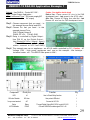
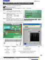
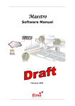
USB9501-12 DAQ Kit Application Example 1
Caution : You might be electric shock
Before Use,Please connect AC wire to the DAQ
development board,Last connect to the AC110 outlet。
After Use,Remove AC110plug from outlet first,Last
Remove AC wire from the DAQ development board。
Subject:Use DAQ kit,Control AC110V。
Type:Digital Output Application。
Virtual Instrument Type:DC power supply(DC
5V output)
Step1: Choose component that you need, In
this example choose Relay and LED。
Step2: Choose Pin that you need , In this
example choose Pin is:
PIN 21:Digital Output 0
PIN30: PC +5V, PIN 40: GND
Step3: Relay is controlled by Digital Output,
Use PIN 21 as the Digital Output,
Use (Control AC110.vi / .csproj / .vbproj)
﹙PS.: LED is use to display Relay
status,connect to VCC and GND)
Step4: This example can use on appliances,as AC110 switch controlled by PC(Caution:AC
Voltage 110V, High power appliances can’t use on this example,Like hairdryer,
hot-water heater ..etc,This RELAY Max power is 24W)
Component
Circuit pos.
Function
Q’ty
LED
L0
Use to Check Relay function
1
200 ohm Resistor
200 ohm
Use protect LED short
1
3 way screw terminal
AC
Connect to AC110V
1
Relay
Relay
Through Digital Output Bit 0 DC5V control AC110V
1
40 PIN Header
IDC40
Connect USB DAQ module signal PIN 1~40
1
29
Bentech Computer Corp.
7F-3, NO.23, LANE 169, KANG-NING ST., HIS-CHIH, TAIPEI HSIEN, TAIWAN, R.O.C.
FAX: (886)02-26958911 TEL.:(886)02-26958906
Web Site www.bentech-taiwan.com
USB9501 Series
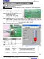
USB9501-12 DAQ Kit Application Example 2
Subject:Use DAQ kit,IR sensor object pass。
Type:Analog Input Application。
Virtual Instrument Type:DC power supply(DC 5V output),Oscilloscope。
Step1: Choose component that you need, In
t h is example choose IR sensor。
Step2: Choose Pin that you need,In this
example choose Pin is:
PIN 1: CH0 IN , PIN 3: AGND,
PIN30: PC +5V, PIN 31: GND,
PIN 40: GND
Step3: IR sensor is connect to Analog Input,Use (IR sensor object pass.vi / .csproj / .vbproj),
(PS: When object pass(IR cut off),IR sensor object pass counter will increase,time delay
default is 200ms,use to avoid one object pass But multi counted)
Step4: This example can use on factory automation
Component
Circuit pos.
Function
Q’ty
LED
L0
Use To generate IR light
1
200 ohm resistor
200 ohm
Use protect LED short
1
IR sensor
IR Sensor
Through Analog Input Bit 0 detect object pass through
1
40 PIN Header
IDC40
Connect USB DAQ module signal PIN 1~40
1
30
Bentech Computer Corp.
7F-3, NO.23, LANE 169, KANG-NING ST., HIS-CHIH, TAIPEI HSIEN, TAIWAN, R.O.C.
FAX: (886)02-26958911 TEL.:(886)02-26958906
Web Site www.bentech-taiwan.com
USB9501 Series
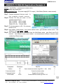
USB9501-12 DAQ Kit Application Example 3
Subject:Use DAQ kit,detect room temperature。
Type:Analog Input Application。
Virtual Instrument Type:DC power supply(DC 5V output),Multi-Meter (DC current measurement)。
Step1: Choose component that you need, In
this example choose temperature
sensor。(DC current output)
Step2: Choose Pin that you need,In this
example choose Pin is:
PIN 2: CH1 IN ,PIN 3: AGND
PIN30: PC +5V, PIN 40: GND
Step3: temperature sensor is DC current output ,It will need add 910Ω resistor and 250Ω
variable resistor ,transform current value to be the voltage value (V=I*R),Then DAQ
module will take the voltage vale as the temperature value。The 250Ω variable resistor as
the temperature adjust,It use (Room temperature.vi / .csproj / .vbproj)
Step4: This example can use on room temperature。
Component
Circuit pos.
Function
Q’ty
Temp. sensor
Temp. sensor
Through Analog Input Bit 1 detect room temperature
1
40 PIN Header
IDC40
Connect USB DAQ module signal PIN 1~40
1
910 ohm resistor
910 ohm
Use transform temp. sensor current to be voltage
1
VR 250 ohm
VR 250 ohm
Use to adjust temperature (Fix current x variable resistor)
1
31
Bentech Computer Corp.
7F-3, NO.23, LANE 169, KANG-NING ST., HIS-CHIH, TAIPEI HSIEN, TAIWAN, R.O.C.
FAX: (886)02-26958911 TEL.:(886)02-26958906
Web Site www.bentech-taiwan.com
USB9501 Series
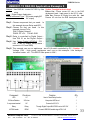
USB9501-12 DAQ Kit Application Example 4
Subject:Use DAQ kit,measurement resistor value。
Type:Analog Input Application。
Virtual Instrument Type:DC power supply(DC 5V output),Multi-Meter (Resistor measurement)。
Step1: Choose component that you need, In
Step2:
Step3:
Step4:
Step5:
this example choose resistor。
Choose Pin that you need,In this
example choose Pin is:
PIN 1: CH0 IN ,PIN 2: AGND
PIN 3: CH1 IN ,PIN 4: AGND
PIN30: PC +5V, PIN 40: GND
Put known resistor to R0,Put unknown
resistor to R1。
Use resistor voltage divide,from known resistor value,get unknown resistor value,Use
(Resistor value.vi / .csproj / .vbproj)
This example can use to understand how the Multi-Meter works,and Ohm's law R=V/I
formula, use different known value resistor,can measurement different unknown value
resister by different range。
Component
Circuit pos.
Function
Q’ty
Resistor
R0
Use to choose known resistor range 200Ω,2KΩ,20KΩ
3
2 way screw terminal
R0
Connect to unknown resistor
1
2 way screw terminal
R1
Connect to known resistor
1
40 PIN Header
IDC40
Connect USB DAQ module signal PIN 1~40
1
32
Bentech Computer Corp.
7F-3, NO.23, LANE 169, KANG-NING ST., HIS-CHIH, TAIPEI HSIEN, TAIWAN, R.O.C.
FAX: (886)02-26958911 TEL.:(886)02-26958906
Web Site www.bentech-taiwan.com
USB9501 Series
USB9501-12 DAQ Kit Application Example 5
Subject:Use DAQ kit,control AC110V by Use
voice
Type:Digital Output Application。
Virtual Instrument Type:DC power supply(DC
5V output)
Caution : You might be electric shock
Before Use,Please connect AC wire to the DAQ
development board,Last connect to the AC110 outlet。
After Use,Remove AC110plug from outlet first,Last
Remove AC wire from the DAQ development board。
Step1: Choose component that you need, In
Step2:
Step3:
Step4:
Step5:
this example choose Relay and LED。
Choose Pin that you need , In this
example choose Pin is:
PIN 21:Digital Output 0
PIN30: PC +5V, PIN 40: GND
Relay is controlled by Digital Output,
Use PIN 21 as the Digital Output,
Use (Voice Control AC110.vi) ﹙ PS. :
LED is use to display Relay status,
connect to VCC and GND)
This example can use on appliances,as AC110 switch controlled by PC(Caution:AC
Voltage 110V, High power appliances can’t use on this example,Like hairdryer,
hot-water heater ..etc,This RELAY Max power is 24W)
Component
Circuit pos.
Function
Q’ty
LED
L0
Use to Check Relay function
1
200 ohm Resistor
200 ohm
Use protect LED short
1
3 way screw terminal
AC
Connect to AC110V
1
Relay
Relay
Through Digital Output Bit 0 DC5V control AC110V
1
40 PIN Header
IDC40
Connect USB DAQ module signal PIN 1~40
1
Bentech Computer Corp.
7F-3, NO.23, LANE 169, KANG-NING ST., HIS-CHIH, TAIPEI HSIEN, TAIWAN, R.O.C.
FAX: (886)02-26958911 TEL.:(886)02-26958906
Web Site www.bentech-taiwan.com
33
USB9501 Series
Trademarks
Microsoft® Visual Basic® 、 Visual C/C++® and .NET® are either registered
trademarks or trademarks of Microsoft Corporation in the United States and/or other
countries.
MATLAB® is registered trademarks or trademarks of MathWorks Corporation in the
United States and/or other countries.
LABVIEW® is registered trademarks or trademarks of National Instrument Corporation
in the United States and/or other countries.
TracerDaq® 、 InstaCal® 、 UNIVERSAL LIBRARY® 、 UNIVERSAL LIBRARY for
Labview®、Softwire®、USB DAQ module® H/W & S/W are registered trademarks or
trademarks of Measurement Computing Corporation in the United States and/or other
countries.
USB9501-14 DAQ module
USB 2.0 interface
Eight single-ended 13-bit analog
input A/D, 48kS/s
Or four differential 14-bit analog
input A/D, 48kS/s
Two 12-bit analog outputs D/A
16 digital input or 16 digital output
USB9501-14 DAQ Kits
DAQ development board and BOM
DAQ development board circuit
DAQ development board components
Bare development board
VB,VC, Boland C example & source code
Microsoft .NET 2003 example & source
code
LABVIEW example & source code
TracerDaq function, display and record DAQ
data
InstalCal function, display DAQ data
Matlab support, write your mathematical
model today
Support Microsoft .NET 2005 (Option)
Support Excel Wizard (Option)
Support DasyLab (Option))
One year warranty
(Excluded components on DAQ
development board)
User Manual
Reserve the right to change the design and. specification without notice。
34
Bentech Computer Corp.
7F-3, NO.23, LANE 169, KANG-NING ST., HIS-CHIH, TAIPEI HSIEN, TAIWAN, R.O.C.
FAX: (886)02-26958911 TEL.:(886)02-26958906
Web Site www.bentech-taiwan.com