1
Design and Construction of a Reflow Soldering Oven
Solomon Gebre, Keith E. Johnson, William Joshua Russell, and Clement Sung-Jay Sun
{gebres, xenon1, wjar, sunc}@u.washington.edu
Dept of EE, University of Washington
Seattle WA, 98195-2500
UWEE Technical Report
Number UWEETR-2006-0010
June 16, 2006
Department of Electrical Engineering
University of Washington
Box 352500
Seattle, Washington 98195-2500
PHN: (206) 543-2150
FAX: (206) 543-3842
URL: http://www.ee.washington.edu
EE 449, UNIVER SITY OF WASHINGTON
DESIGN AND CONSTRUCTION OF A
REFLOW SOLDERING OVEN
PR EPAR ED BY T HE S UP ER HIG H INT E LL IG EN C E T EAM :
SOLOMON C. GEBRE
KEITH ERIC JOHNSON
WILLIAM JOSH RUSSELL
CLEMENT SUNG-JAY SUN
J U N E 2 , 2 00 6
DEDICATED TO:
ALL THOSE GREAT SOULS THAT HAVE TOUCHED OUR LIVES…
…AND IN DOING SO MADE THEM BETTER.
EXECUTIVE SUMMARY
Within this summary, the goals, methods, and results of the design and construction of a reflow
soldering oven will be discussed.
The goal of this project was simply to produce a reflow soldering oven for the Professor Blake
Hannaford’s Biorobotics Lab at the University of Washington. It had to track a temperature profile
to produce superiorly soldered joints on surface mounted components. The development team
decided to convert a conventional toaster oven to this purpose. While initially only for one particular
lab, the customer decided to transfer the oven to the entire electrical engineering department for
general use. It now is located in Bill Lynes laboratory.
The physical construction of the toaster oven was key in the design process. After all, all the transfer
functions and modeling would be based on the oven’s physical properties. Modifications included
removing the dials and much of the internal circuitry. Only three holes were made into the oven
case. Two of these holes accommodated the temperature sensor while the last allowed for
connections to be made with the solid-state power relay. Later, a protective box was bolted into the
side of the toaster to house the relay, circuit boards, and provide for an attachment point of an I/O
card.
Once the oven was ready, testing was conducted to determine the various parameters in its
mathematical model. These measurements included the rise time of the oven, the time delay in the
heating elements, and the oven’s heating/cooling rate. At the same time, modeling was done with
estimated parameters in preparation for arrival of the actual. Simulations were done on the step and
ramp responses of the oven with these estimated parameters. When the actual parameters were
determined, they were input into the pre-existing models and simulated as well. Overall, the
simulations showed that the oven was capable of accomplishing its performance criteria.
Actual tests on step inputs showed the oven’s response to either be underdamped with large ring or
overdamped with a large settling time. Ramp inputs did not perform well either. Both inputs also
never fully utilized the limits of the oven so the control was split between open and closed loop.
During the rising of the temperature open loop would be used to turn the oven “all on” such that
the minimal rise time could be reached. In between rises, during areas of relative plateaus, a closed
loop controller was used to careful control the temperature. At the end of the process, the open
loop control was shutdown the heating elements.
Cooling proved to be a concern with the oven. While a convection fan distributed heat equally
throughout the oven, it did not expedite cooling when the heating elements were turned off.
Therefore, it was decided that a small level of user input would be needed. Through a graphical user
interface (GUI), the user would be told to open the oven door to help cool the interior of the oven
and any parts therein.
Programming was done to create the controllers in MATLAB. In addition, the GUI was also done
in MATLAB. A small amount of circuit design was also done to integrate all the hardware together.
Ultimately, the results of the oven were very good. The oven was used to solder the boards of
another development team in charge of a shaker table. Though slightly overcooked, their boards
worked perfectly. Upon further refinement of the temperature profile, another board belonging to
Professor Eric Klavin’s Self Organizing Systems Lab was also done—this time with no sign of board
discoloration. In all cases, the solder joints were comparable to those done in a professional setting
and no difference between the two was observed.
i
TABLE OF CONTENTS
Page
Executive Summary ............................................................................................................................................. i
Table of Contents ................................................................................................................................................ ii
List of Tables ........................................................................................................................................................ iv
List of Figures....................................................................................................................................................... v
Chapter 1: Problem Characterization................................................................................................................
Introduction...................................................................................................................................................
Customer ........................................................................................................................................................
Performance Criteria ....................................................................................................................................
Plant and Controller Identification and Description ...............................................................................
Cost and Schedule Constraints ...................................................................................................................
System Inputs and Interfaces ......................................................................................................................
Project Plan ....................................................................................................................................................
Technical Obstacles ......................................................................................................................................
Team Management .......................................................................................................................................
1
1
1
1
2
2
3
3
5
5
Chapter 2: System Modeling .............................................................................................................................. 6
Introduction................................................................................................................................................... 6
System Model................................................................................................................................................. 6
Plant/Actuator Model .................................................................................................................................. 6
Controller Model........................................................................................................................................... 8
Sensor Model ................................................................................................................................................. 9
Technical Obstacles ......................................................................................................................................10
Management Report .....................................................................................................................................10
Chapter 3: Control Design .................................................................................................................................11
Introduction...................................................................................................................................................11
Control Gain Calculation.............................................................................................................................11
Time Domain Simulation.............................................................................................................................12
Performance Prediction ...............................................................................................................................13
Stability Margins ............................................................................................................................................13
Sensitivity to Parameter Changes................................................................................................................14
Hardware and Software Architecture.........................................................................................................14
Risk and Hazard Analysis ............................................................................................................................16
Revised Project Plan .....................................................................................................................................17
Technical Obstacles ......................................................................................................................................17
Management Report .....................................................................................................................................17
Chapter 4: Detailed Design ................................................................................................................................18
Introduction...................................................................................................................................................18
Electrical Hardware and Wiring Design ....................................................................................................18
Software Programming.................................................................................................................................19
Mechanical Design........................................................................................................................................20
Safety Review and Protection System Design ..........................................................................................21
Technical Obstacles ......................................................................................................................................21
Management Report .....................................................................................................................................21
ii
TABLE OF CONTENTS CONTINUED
Page
Chapter 5: Project Implementation...................................................................................................................22
Introduction...................................................................................................................................................22
System Construction.....................................................................................................................................22
Initial Testing .................................................................................................................................................23
Performance and Stability Testing..............................................................................................................24
Customer Reception .....................................................................................................................................28
Technical Obstacles ......................................................................................................................................28
Management Report .....................................................................................................................................28
Appendix...............................................................................................................................................................29
Matlab Code...................................................................................................................................................29
User Manual...................................................................................................................................................42
Acknowledgments................................................................................................................................................46
EE 449 Design of Automatic Control Systems........................................................................................46
Department of Electrical Engineering.......................................................................................................46
Authors..................................................................................................................................................................47
Solomon Gebre .............................................................................................................................................47
Keith Johnson................................................................................................................................................47
William Josh Russell .....................................................................................................................................47
Clement Sun...................................................................................................................................................47
iii
LIST OF TABLES
Table 1-1:
Table 1-2:
Table 1-3:
Table 1-4:
Table 2-1:
Table 2-2:
Table 2-3:
Table 3-1:
Page
Bill of Materials for Reflow Solder Oven ................................................................................. 2
Reflow Solder Oven Work Breakdown .................................................................................... 3
Rated Skills of Reflow Solder Oven Personnel ....................................................................... 4
Skill Requirements for Development Tasks............................................................................. 5
Relationship Between Duty Factor, Power, and Temperature.............................................. 8
Determination of τb and τd ........................................................................................................... 8
Temperature at Thermocouple Based on Conditioner Output ............................................10
Revised Reflow Solder Oven Work Breakdown .....................................................................17
iv
LIST OF FIGURES
Figure 1-1:
Figure 2-1:
Figure 2-2:
Figure 2-3:
Figure 2-4:
Figure 2-5:
Figure 3-1:
Figure 3-2:
Figure 3-3:
Figure 3-4:
Figure 3-5:
Figure 3-6:
Figure 3-7:
Figure 3-8:
Figure 4-1:
Figure 4-2:
Figure 4-3:
Figure 5-1:
Figure 5-2:
Figure 5-3:
Figure 5-4:
Figure 5-5:
Figure 5-6:
Figure 5-7:
Figure 5-8:
Figure 5-9:
Figure 5-10:
Figure 5-11:
Page
Temperature Profile for Convection Reflow....................................................................... 2
Reflow Solder Oven High Level System Model ................................................................. 6
K Value Determination .......................................................................................................... 7
PID Controller Schematic from EE 448 Temperature Control....................................... 8
Step Response of Toaster Oven Using SISOTOOL ......................................................... 9
Temperature Sensor Model.................................................................................................... 9
Realistic Simulink Block Diagram .........................................................................................11
Ramp Response of Realistic Simulink Simulation ..............................................................12
The Bode Diagram Used to Determine System Gain and Phase Margin .......................13
Step Response of the System Using SISOTOOL ..............................................................13
Hardware Schematic of Reflow Soldering Oven ................................................................15
Software Pseudocode for Oven Temperature Control......................................................15
Software Architecture for Oven Temperature Control .....................................................16
Revised Project Plan Flow Chart and Critical Path in Green ...........................................17
Hardware Wiring Diagram .....................................................................................................18
Simplified MATLAB Code for Control of Reflow Oven .................................................19
MATLAB GUI for Reflow Oven .........................................................................................20
Photograph of Reflow Oven, Temperature Sensor, and I/O Card.................................22
Response of Reflow Solder Oven to a 150 °C Step ...........................................................23
Temperature Profile of Combined Open/Closed Loop Control.....................................24
Temperature Profile without Fan and Tray in Lowest Position.......................................24
Temperature Profile with Rack on Highest Position without Tray .................................25
Temperature Profile with Board and Tray in Lowest Position and with Fan ................25
Temperature Profile with Board and Tray in Lowest Position and Fan .........................26
Temperature Profile with Optimal Settings and Major Door-Open Disturbance.........26
Boards which have Successfully Endured the Process of Reflow Soldering ..................26
Finished PCB Board................................................................................................................27
Finalized GUI Showing Performance of Oven ..................................................................28
v
CHAPTER 1: PROBLEM CHARACTERIZATION
INTRODUCTION
Reflow solder is used to attach surface mounted components to a circuit board. The desired effect is
adherence of these components to the board by melting the solder particles in the applied paste,
allowing their surfaces to wet and join together, and finally solidifying as soon as the heat is removed.
Resulting from this process is a strong metallurgical bond between the components and the board.
The process is also faster and less expensive than soldering individually components by hand with
an iron. It is therefore economically practical to obtain such reflow soldering ovens if their
capabilities are used with relatively high frequency.
CUSTOMER
The organizational customer for the reflow oven was the Biorobotics Lab of the Electrical
Engineering Department at the University of Washington. The points of contact were Professor
Blake Hannaford, Phil Roan, and Jesse Dosher. The purpose of this project was to develop a reflow
soldering oven for printed circuit boards suitable for use in small batch prototyping in Professor
Hannaford’s Biorobotics Lab at the University of Washington. The device may be used by other
laboratories as well. It allows for an adjustable temperature profile via a graphical user interface on a
connected computer.
PERFORMANCE CRITERIA
The project team developed a reflow soldering oven using a domestically available toaster oven and
temperature controller, which was also designed and constructed. Further, the required temperature
cycle calls for accurate control and temperature changes in the range of 20 to 50 °C per minute. The
oven must also be large enough to accommodate small PC boards and reach temperatures high
enough to melt a range of solders. Finally, the oven must be able to cool with sufficient speed in
order to avoid damage to the electronics on the board being soldered. A graphical user interface will
also be developed to aid the user in the use of the oven.
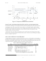
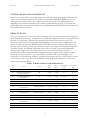
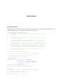
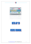
A generic temperature profile of the oven with respect to time is shown in Figure 1-1. The profile
was also customizable. That is, preheat, flux activation, reflow, and cool times were to be adjustable.
EE 449
REFLOW SOLDER OVEN
CHAPTER 1
Figure 1-1: Temperature Profile for Convection Reflow 1
PLANT AND CONTROLLER IDENTIFICATION AND DESCRIPTION
For the reflow soldering oven, the heating elements will be the primary plant as this project involves
controlling the heat of the system. If the oven is unable to cool relatively quickly, then the added
fans will be the secondary plants. In place of fans, simply opening the door may suffice for cooling.
For both of these systems, controllers may necessary and the systems will be placed in unity
feedback creating a closed loop system.
A temperature sensor also makes an appearance in the overall system and is integral in the control
process. Lastly, an analog-to-digital converter will be used to convert the sensor readings into digital
data for a computer to process.
COST AND SCHEDULE CONSTRAINTS
Available budget was limited to roughly 200 USD. The oven was to be delivered by the beginning of
June 2006. No real schedule constraints were foreseen. Time, in the magnitude of one to two weeks,
was all that was required for parts to arrive. The oven itself was procured in relatively little time once
a quick trade study was completed. The bill of materials is shown in Table 1-1.
Item
Toaster Oven
Power Relay
Thermocouple
Conditioner
Protoboard
Op-Amp
I/O Card
1
Table 1-1: Bill of Materials for Reflow Solder Oven
Description
Cost (USD)
Black and Decker Convection Toaster Oven, Black
40
Solid State Power Relay with Large Heat Sink, Used
30
T-Type Digikey Thermocouple
39
K-Type AD595 Digikey Conditioner
20
Used
15
Chip Contains Four Op-Amps, Borrowed
0
USB 1208FS I/O Card, Borrowed
120
Total Cost Excluding Barrowed Items (USD)
144
Altera Corporation. “Reflow Soldering Guidelines for Surface-Mount Devices.” June 2002. Version 4.
2
EE 449
REFLOW SOLDER OVEN
CHAPTER 1
SYSTEM INPUTS AND INTERFACES
Inputs to the system will be the desired temperature and error signal upon taking a difference with
respect to the temperature sensors. The output is a pulse-width modulated (PWM) wave to the
heating elements and possibly a step output to the fans. The width of the PWM signal varies
depending on the desired temperature. The software system interface consists of a start button,
profile-adjust dial, and temperature display. It was implemented in MATLAB but will be made into
an executable for convenience.
PROJECT PLAN
The goal of the project is to develop a reflow soldering oven for printed circuit boards suitable for
use in small batch prototyping. It will allow for an adjustable temperature profile via a graphical user
interface on a connected computer. The organizational customer for the reflow oven is the
Biorobotics Lab of the Electrical Engineering Department at the University of Washington. The
points of contact are Professor Blake Hannaford, Phil Roan, and Jesse Dosher. This project will
develop a reflow soldering oven using a domestic toaster oven and professional grade temperature
controller. Further, the required temperature cycle calls for accurate control and temperature
changes in the range of 20 to 50 °C per minute. The oven must also be large enough to
accommodate small PC boards and reach temperatures high enough to melt a range of solders.
Finally, the oven must be able to cool with sufficient speed in order to avoid damage to the
electronics on the board being soldered. A graphical user interface will also be developed to aid the
user in the use of the oven. The work breakdown for the design and construction of the reflow
solder oven is shown in Table 1-2.
Table 1-2: Reflow Solder Oven Work Breakdown
Task
No.
1.0
All
Start
Date
3-Apr
End
Date
7-Apr
Dependant
Tasks
All
Prerequisite
Tasks
N/A
All
8-Apr
11-Apr
2.1
N/A
All
11-Apr
14-Apr
3.0, 4.2, 6.1
2.0
Josh, Keith
Josh, Keith
N/A
11-Apr
13-Apr
14-Apr
13-Apr
14-Apr
21-Apr
3.1
3.2
4.0, 5.0
2.0, 2.1
3.0
3.1
Solomon, Clement
29-Apr
2-May
4.1
3.2
Solomon, Clement
3-May
5-May
4.2
4.0
Controller Design
Solomon, Clement
6-May
12-May
6.0
2.1, 4.1
Hardware Assembly
Computer Interface
Control Software
Development
GUI Development
System Testing
System Revision
Josh, Keith
Keith
22-Apr
26-Apr
25-Apr
28-Apr
5.1
7.0
3.2
5.0
Josh
13-May
19-May
7.0
4.2
Josh
All
All
13-May
20-May
24-May
19-May
23-May
30-May
7.0
7.1
8.0
2.1
5.1, 6.0, 6.1
7.0
Task
Lead
4.1
Project Plan
Research of Professional
Solder Techniques
Controller Specification
Derivation
Hardware Research
Hardware Request
Hardware Reception
Plant Transfer Function
Determination
System Modeling
4.2
5.0
5.1
2.0
2.1
3.0
3.1
3.2
4.0
6.0
6.1
7.0
7.1
3
EE 449
8.0
REFLOW SOLDER OVEN
Report Compilation
Clement
25-May
CHAPTER 1
1-Jun
N/A
All
The task descriptions are discussed below.
1.0) Project Plan: Determine objective, tasks, and path of completion for the project.
2.0) Research of Professional Solder Techniques: Determine necessary hardware components and
techniques for reflow soldering.
2.1) Controller Specification Derivation: Determine rise time, overshoot, system order, etc.
3.0) Hardware Research: Find hardware capable of achieving specifications.
3.1) Hardware Request: Place order for delivery of all necessary hardware.
3.2) Hardware Reception: Final procurement of all necessary hardware.
4.0) Plant Transfer Function Determination: Run tests to determine the transfer function of the
toaster oven.
4.1) System Modeling: Use MATLAB to build a realistic model of the system.
4.2) Controller Design: Use MATLAB and associated tools to build a controller for the toaster
oven.
5.0) Hardware Assembly: Make necessary modifications to toaster and implement a sensor.
5.1) Computer Interface: Connect toaster oven to computer via an interface so that software can
run from the computer to control temperature.
6.0) Control Software Development: Build the controller in MATLAB.
6.1) GUI Development: Build a GUI to interface with the toaster oven so that a user does not need
to deal directly with code. Eventually there should be an executable.
7.0) System Testing: Test the hardware and software for functionality.
7.1) System Revision: Troubleshoot and debug problems in the system.
8.0) Report Compilation: Compiling the report from previous milestone reports detailing the
specifics and development of the final product.
For task dependencies, see Table 1-2.
The development group consists of four senior undergraduates in Electrical Engineering. Their skills
are rated below in Table 1-2. They are rated on a scale from 0 to 3. Zero having absolutely no ability
in that area whatsoever and three, having achieved complete and utter mastery.
Table 1-3: Rated Skills of Reflow Solder Oven Personnel
S. Gebre
K. Johnson
W. Russell
C. Sun
Electromechanical
Hardware Skills
2
2
3
1
Computer Skill
Electronics Skill
MATLAB Skill
2
2
3
2
2
2
2
2
3
1
2
2
Theoretical
Ability
3
1
1
2
In addition to the personnel skills, the estimated skill requirements for the tasks listed in Table 1-2
are shown in Table 1-4.
Available budget is limited to roughly 200 USD. However, private funds will be accessed if need be.
The development team will rely partly on sampled products in the construction of the reflow solder
4
EE 449
REFLOW SOLDER OVEN
CHAPTER 1
oven. Such components will take several weeks to arrive. However, the oven itself can be procured
in little time at a cost exceeding no more than 50 USD. A trade study will be conducted by
contractors to determine the best brand and model.
The development team will utilize laboratories in Sieg Hall and the Electrical Engineering Building
on the University of Washington campus. These facilities are believed to be ample in available space
and no conflicts with other groups are expected.
Task
No.
1.0
2.0
2.1
3.0
3.1
3.2
4.0
4.1
4.2
5.0
5.1
6.0
6.1
7.0
7.1
8.0
Table 1-4: Skill Requirements for Development Tasks
Electromechanical
Hardware Skills
0
0
2
2
0
0
3
0
0
3
1
0
0
1
3
1
Computer Skill
Electronics Skill
MATLAB Skill
Theoretical Skill
0
0
0
0
0
0
0
0
0
0
2
3
3
1
3
1
0
0
1
1
0
0
3
0
0
3
2
0
0
1
3
1
0
0
0
0
0
0
0
2
2
0
2
3
3
1
3
1
2
1
2
2
0
0
3
3
2
1
1
2
1
1
3
1
All group members will be responsible for entering tasks in the online project management plan.
With regard to task status, group members will update their own status. Mr. Johnson will be
responsible for updating the wiki twice per week on Tuesdays and Fridays by 5:00 pm. Mr. Sun will
provide web space for the reports.
TECHNICAL OBSTACLES
No technical obstacles were faced in the first two weeks of the project.
TEAM MANAGEMENT
The development team members were on speaking terms. Work was equally distributed and
communication between individuals was civil and most polite.
5
CHAPTER 2: SYSTEM MODELING
INTRODUCTION
The most critical component of any control design is to obtain approximated linear models of the
various parts of the equipment. This chapter deals with the modeling of the system. For the reflow
solder oven, the system is composed of the oven heating element, which also serves as the actuator,
the controller, the sensor, and the computer interface input/output card.
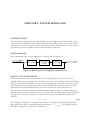
SYSTEM MODEL
The system model is not overly complicated. It is shown below in Figure 2-1.
Figure 2-1: Reflow Solder Oven High Level System Model
PLANT/ACTUATOR MODEL
The toaster oven that will be given the new task of soldering circuit boards has not yet been
acquired. However, it is expected to be a forced air convection oven to distribute the heat uniformly
through out the PCB. The transfer function of the heating element is expected to be similar to that
of the Temperature Control Laboratory (TCL) board from EE 448: Actuators and Sensors. That
model assumes the plant transfer function to be linear and have the form of Equation 2-1.
Since the toaster oven deals with the dispersion and introduction of heat to a system, a simple yet
effective model would follow Newton’s Law of Cooling, a first order differential equation. Modified
for purposes of this project, Equation 2-1 represents the system with additional constants and
variables.
τ b x& + x = Ku
(2-1)
The variable, u, in Equation 2-1 represents the duty factor of the pulse-width modulated (PWM)
input signal. The variable, x, represents temperature where x = Toven temperature. By taking the Laplace
Transform of Equation 2-1 the result is Equation 2-2.
EE 449
REFLOW SOLDER OVEN
CHAPTER 2
(2-2)
τ b sX ( s ) + X ( s ) = K U ( s )
The frequency domain transfer function derived from Equation 2-2 is shown in Equation 2-3.
G( s ) =
(2-3)
Y (s )
e − sτ d X ( s )
K − sτ d
e
=K
=
U(s )
τ b sX ( s ) + X ( s ) τ b s + 1
Hence, the toaster oven is modeled by the transfer function in Equation 2-3. To complete the
system model, the values for K, τb, and τd must be determined. In the future, the oven can be
controlled by using Equation 2-3 as the model for the system. In our case we will assume K will be
dependent on the power output of the oven and the temperature at full blast. If we assume the rated
power output of the oven being around 1500 W and at full blast the oven temperature can reach 300
°C hence, K ≈ 5. Originally we assumed the value of τb to be 20 seconds and τd to be 5 seconds.
In determining the actual value of K, the steady state temperature of the oven must be compared to
the duty factor of the PWM signal that is input into the system. To determine τd, the delay between
the time when the PWM is input and when the sensors begin to detect a change in temperature is
measured. Finally, in determining τb, the intersection of the steady state temperature and the line
created by drawing a straight line up along the maximum slope of the temperature output y(t) must
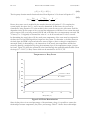
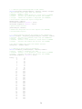
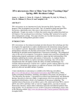
be found. Figure 2-2 shows the resultant K value found through the method described earlier. From
the slope, K = 2.29 °C/% Duty Factor which can be translated to 0.1702 °C/W.
Temperature vs. Duty Factor
360
340
Temperature (C)
320
300
y = 2.2971x + 109.38
280
R2 = 0.9911
260
240
220
200
50
60
70
80
90
100
Duty Factor (%)
Figure 2-2: K Value Determination
Since the duty factor is an actual percentage of the maximum voltage, it is possible to extract the
relationships between temperature, duty factor, and wattage. Table 2-1 shows these relationships.
7
EE 449
REFLOW SOLDER OVEN
CHAPTER 2
Table 2-1: Relationship Between Duty Factor, Power, and Temperature
Temperature (°C) Duty Factor (%) Power (W)
219
50
675
250
60
810
272
70
945
297
80
1080
318
90
1215
334
100
1350
Similarly, the two time constants were found. The data used to find them and the values themselves
are shown in Table 2-2.
Table 2-2: Determination of τb and τd
Duty Factor (%) ti (s)
tf (s)
τb (Δt) (s)
τd (s)
50
31
694
663
31
60
35
631
596
35
70
35
580
545
35
80
40
572
532
40
90
40
566
526
40
100
39
496
457
39
Average
Standard Deviation
553.17
69.86
36.67
3.61
CONTROLLER MODEL
The development group believed that a PID controller similar to the temperature control lab in EE
448: Actuators and Sensors would suffice. As with all controllers which utilize an integrator, an antiwindup system is necessary to reduce accumulated integration error. All that need be done is
redesign of the gains. The general schematic for the PID controller is as shown in Figure 2-3.
KP
PID Controller
0.25
+
–
KD
s
+
+
+
Constant
GTCL Board(s)
Output
Plant
KI
+
–
1/s
KW
+
–
Anti-Windup
Sub-System
Figure 2-3: PID Controller Schematic from EE 448 Temperature Control
8
EE 449
REFLOW SOLDER OVEN
CHAPTER 2
Unfortunately, upon testing the controller with the actual hardware, it was determined through
much trial and error that a PID controller was overkill. That is, the differential term was not
necessary. This is discussed in more detail in the next chapter. However, the MATLAB used to
perform the control calculations retains the parameter in case the customer wishes to make changes
to the controller. For the current system however, Kd is set to zero thus effectively removing it from
the transfer function and all control calculations.
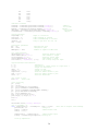
SISOTOOL was used to determine the gains of the PID controller for the approximated parameters
of the plant model. The result of the step response is as shown in Figure 2-4. The SISOTOOL result
has a nice rise time of 0.567 s and settling time of 4.01 s with a slight overshoot of 1.46%. It should
be noted that extremely high gains were used and that future experiments had gains reduced while
maintaining the ratios between them and have the luxury of better model parameters.
Step Response
155
System: Closed Loop: r to y
I/O: r to y
Peak amplitude: 152 System: Closed Loop: r to y
I/O: r to y
Overshoot (%): 1.46
Settling Time (sec): 4.01
At time (sec): 1.54
150
Amplitude
ystem: Closed Loop: r to y
I/O: r to y
145(sec): 0.567
Rise Time
140
135
130
0
0.5
1
1.5
2
2.5
3
3.5
4
4.5
Time (sec)
Figure 2-4: Step Response of Toaster Oven Using SISOTOOL
SENSOR MODEL
Based on the specifications, the voltage of the device changes in relation with temperature and is
extremely linear over a large range of temperatures. Unfortunately, the voltage output is extremely
small. An AD595 conditioner integrated circuit allows the thermocouple to be used. From the
datasheets provided by the manufacturers of the thermocouple and conditioner, it is possible to
correct the “incompatibility” of the T and K type devices through a series of output voltage
conversions. A table was constructed which will allow a person or program to look up the correct
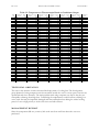
temperature when provided an output from the conditioner, it can be seen in its truncated form in
Table 2-3. The model for the temperature sensor is shown in Figure 2-5.s
Figure 2-5: Temperature Sensor Model
9
EE 449
REFLOW SOLDER OVEN
CHAPTER 2
Table 2-3: Temperature at Thermocouple Based on Conditioner Output
Temp.
(°C)
20
21
22
23
24
25
26
27
28
29
30
31
32
33
34
35
36
37
38
39
40
41
42
43
44
45
46
47
48
49
50
51
52
53
54
55
56
57
58
59
60
Conditioner Temp. Conditioner Temp. Conditioner Temp. Conditioner Temp. Conditioner Temp. Conditioner Temp. Conditioner
(°C)
(°C)
(°C)
(°C)
(°C)
(°C)
Output
Output
Output
Output
Output
Output
Output
198
61 624
102 1084
143 1574
184 2091
225 2637
266 3197
208
62 635
103 1095
144 1587
185 2104
226 2650
267 3212
218
63 646
104 1107
145 1599
186 2117
227 2664
268 3226
228
64 656
105 1118
146 1611
187 2130
228 2677
269 3240
238
65 667
106 1130
147 1624
188 2143
229 2691
270 3254
248
66 678
107 1142
148 1636
189 2156
230 2704
271 3268
258
67 689
108 1154
149 1649
190 2169
231 2718
272 3282
268
68 700
109 1165
150 1661
191 2182
232 2732
273 3296
278
69 711
110 1177
151 1673
192 2195
233 2745
274 3310
288
70 722
111 1189
152 1686
193 2208
234 2759
275 3324
298
71 733
112 1201
153 1698
194 2221
235 2772
276 3338
309
72 744
113 1213
154 1711
195 2234
236 2786
277 3352
319
73 753
114 1224
155 1723
196 2247
237 2800
278 3367
329
74 766
115 1236
156 1736
197 2260
238 2814
279 3381
339
75 777
116 1248
157 1749
198 2274
239 2828
280 3398
350
76 788
117 1260
158 1761
199 2287
240 2837
281 3412
360
77 799
118 1272
159 1774
200 2299
241 2851
282 3426
370
78 810
119 1284
160 1785
201 2312
242 2864
283 3440
380
79 821
120 1296
161 1798
202 2326
243 2878
284 3455
391
80 833
121 1308
162 1810
203 2339
244 2892
285 3469
401
81 844
122 1320
163 1822
204 2352
245 2905
286 3483
411
82 855
123 1332
164 1835
205 2365
246 2919
287 3497
422
83 866
124 1344
165 1848
206 2378
247 2933
288 3512
433
84 878
125 1355
166 1860
207 2392
248 2947
289 3526
443
85 889
126 1368
167 1873
208 2405
249 2960
290 3540
454
86 900
127 1379
168 1886
209 2418
250 2974
291 3555
464
87 912
128 1392
169 1898
210 2431
251 2988
292 3569
475
88 923
129 1404
170 1911
211 2444
252 3002
293 3583
485
89 934
130 1416
171 1923
212 2458
253 3016
294 3598
496
90 946
131 1428
172 1936
213 2471
254 3029
295 3612
506
91 957
132 1440
173 1949
214 2484
255 3043
296 3626
517
92 969
133 1452
174 1962
215 2498
256 3057
297 3640
528
93 980
134 1464
175 1974
216 2511
257 3071
298 3655
538
94 991
135 1476
176 1987
217 2525
258 3085
299 3670
549
95 1003
136 1488
177 2000
218 2538
259 3099
300 3679
559
96 1014
137 1501
178 2013
219 2551
260 3114
266 3197
570
97 1026
138 1513
179 2026
220 2569
261 3128
267 3212
581
98 1037
139 1525
180 2040
221 2583
262 3142
268 3226
591
99 1049
140 1537
181 2052
222 2596
263 3156
269 3240
602
100 1061
141 1550
182 2065
223 2609
264 3170
270 3254
613
101 1072
142 1562
183 2078
224 2623
265 3184
271 3268
TECHNICAL OBSTACLES
The issue at this juncture in time concerned the deployment of cooling fans. The development
group planned on using computer-case fans mounted outside the oven. Louvers open if the fans are
operational and close otherwise. The main problem with using computer-case fans is that they are
susceptible to damage from high heat. Considering the temperatures at which reflow soldering is to
occur, such fans may be irreparably damaged and thus rendered useless during the critical cooling
process. It was a high priority to resolve this issue and with all haste.
MANAGEMENT REPORT
Since the components did not yet arrive, little work was done until later when the oven was
purchased.
10
CHAPTER 3: CONTROL DESIGN
INTRODUCTION
Control design involves choosing a compensator or controller suitable for the system and which will
help it achieve its performance specifications. For the reflow soldering oven, a PID active controller
was decided most appropriate for the task at hand. The proportional (P), integral (I), and derivative
(D) gains of the controller are difficult to find mathematically. Only simulation has proven to
consistently produce good gains. Actual testing with physical hardware in temperature control can
prove to be extremely time consuming, so simulation is a good way to reduce the time necessary by
reducing the number of gain candidates into a relatively narrow range. With the acquisition of a welltuned controller, the product would be well on its way to completion.
CONTROL GAIN CALCULATION
Unfortunately, no known method has yet been devised for calculating the variables of Kd, Kp, and Ki
such that the system meets performance specifications of any kind, let alone no overshoot. Hence,
they must be chosen intuitively—in other words at random—in a way that results in the most
favorable response. This can be done through guessing the values and simulating the system in a
program such as Simulink. The gains for the PID controller have been determined to be in the ratio
of Kp=1:Kd=0.5:Ki=0.025. These numbers were obtained through simulation using Simulink in
MATLAB. A realistic block diagram is shown below in Figure 3-1.
Figure 3-1: Realistic Simulink Block Diagram
While the rest of this chapter concerns findings with estimated model parameters, something must
be said about the gain calculations used for the actual system. After many hours of testing with the
EE 449
REFLOW SOLDER OVEN
CHAPTER 3
hardware, it was determined that the differential term was unnecessary for successful control of the
oven’s temperature. In addition, the average K value for the oven determined in the last chapter was
not used in favor of 4.3794 which is the K value at high temperatures. While the system should track
a ramp, a step response was considered with a rise time of 180 seconds and overshoot of one
percent. From these performance specifications, the natural frequency ωn has a value of 0.826 and
the damping coefficient ζ of 0.031. The transfer function of the new PI controller in series with the
oven transfer function is shown in Equation 3-1 and the system in unity feedback is described by
Equation 3-2.
G( s ) =
K K ps + Kd
τ bs + 1
s
⎛ ωn2 ⎞
⎜ ⎟(s + a )
G( s )
a
T (s ) =
= 2⎝ ⎠
1 + G( s ) s + 2ζωs + ωn2
(3-1)
(3-2)
Eventually, the values of Kp and Ki were found to be 0.06234 and 0.0391, respectively. However,
these were still not accurate and after even more trial and error, the final values used in the actual
control were 0.01 for Kp and 0.0001 for Ki.
TIME DOMAIN SIMULATION
With the estimated parameters, the system is able to track a ramp input but with substantial delay
error. Please see Figure 3-2. The yellow line represents the input ramp function of one degree
Celsius every second. The blue line is the system. The two lines are very nearly parallel but offset
from each other by the time delay of five seconds. This is due to the delay of five seconds.
Figure 3-2: Ramp Response of Realistic Simulink Simulation
12
EE 449
REFLOW SOLDER OVEN
CHAPTER 3
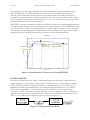
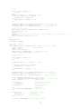
PERFORMANCE PREDICTION
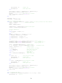
Based on the step response of our system, the performance prediction for our system should be
pretty good; i.e., in terms of percent overshoot, rise and settling time. According to Figure 3-3, for
this system we do not have overshoot, and have fast rise and settling time.
System: Closed Loop: r to y
I/O: r to y
Peak amplitude > 1
Overshoot (%): 0.055
At time (sec) > 15
Step Response
1.02
1
0.98
Amplitude
System: Closed Loop: r to y
I/O: r to y
Settling Time (sec): 8.64
System: Closed Loop: r to y
I/O: r to y
Rise Time (sec): 5.19
0.96
0.94
0.92
0.9
0
5
10
15
Time (sec)
Figure 3-3: Step Response of the System Using SISOTOOL
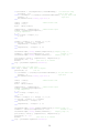
STABILITY MARGINS
To find the stability margin of our system we need to find the gain and phase margin using the Bode
diagram. According to Dorf and Bishop’s Modern Control Systems, “the gain margin is a measure of
how much the system gain would have to be increased for the GH(jω) locus to pass through the
(−1,0 ) point, thus resulting in an unstable system. The phase margin is a measure of the additional
phase lag required before the system becomes unstable.” So, as we can see from Figure 3-4 the
system is stable for any gain and the phase margin is -96.5 deg at 3.97 radians/second.
Bode Diagram
Gm = Inf , Pm = -96.5 deg (at 3.97 rad/sec)
10
Magnitude (dB)
5
0
-5
-10
-15
Phase (deg)
-20
90
45
0
-2
10
-1
0
10
10
1
10
Frequency (rad/sec)
Figure 3-4: The Bode Diagram Used to Determine System Gain and Phase Margin
13
EE 449
REFLOW SOLDER OVEN
CHAPTER 3
SENSATIVITY TO PARAMETER CHANGES
The sensitivity of the system to changes in the parameters K, τb, and τd can be mathematically shown.
Sensitivity is defined in Equation 3-3 and the system transfer function in Equation 3-4.
∂T a
, where a is one parameter and T represents the system
SaT =
(3-3)
∂a T
T (s ) =
K(Kd s 2 + K ps + K i )
s (τ b s + 1)e τ d s + K ( K d s 2 + K p s + K i )
(3-4)
Since the calculations for the sensitivity are very complex, a Texas Instruments TI-89 Titanium
calculator was used. Equation 3-5 shows the sensitivity for K, Equation 3-6 shows sensitivity for τb,
and Equation 3-7 shows sensitivity for τd.
s (τ b s + 1)e τ d s
S =
s (τ b s + 1)e τ d s + K ( K d s 2 + K p s + Ki )
T
K
SτTb =
τ b s 2e τ d s
SτTd =
− τ b s 2e τ d s
+ se τ d s + K ( K d s 2 + K p s + K i )
− τ d e τ d s Ks 2 (τ b s + 1)
s (τ b s + 1)e τ d s + K ( K d s 2 + K p s + K i )
(3-5)
(3-6)
(3-7)
It appears that the system is most sensitive with an increased change in τb and, to a lesser extent,
changes in either direction of K. This makes the most sense because the rise time of the oven is most
critical to its performance whereas delay time and the heating element constant are not.
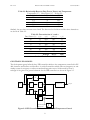
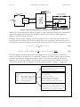
HARDWARE AND SOFTWARE ARCHITECTURE
All major hardware components are shown in Figure 3-5. Ultimately, the PC will control the oven
heating profile as the controller is to be digital and implemented in MATLAB. The USB I/O card
serves as the intermediate between the PC and the oven and temperature sensor. The temperature
sensor requires a +5 V power supply to be provided by the I/O card. It outputs an analog signal in
the range of 0.0 to 5.0 V. The I/O card will feed the input from the temperature sensor to the PC
which will take the appropriate action in controlling the temperature of the oven. The MATLAB
program will send a signal to the I/O which determines the duty factor of the PWM signal. When
the duty cycle is high, +5 V will be placed across the relay allowing the AC current from the wall
outlet to flow through the heating element. When the duty cycle is low, no voltage will be placed
across the relay input and it will switch off the heating element by breaking the circuit.
14
EE 449
REFLOW SOLDER OVEN
CHAPTER 3
Figure 3-5: Hardware Schematic of Reflow Soldering Oven
Software is to be implemented in MATLAB which is to all be encapsulated within the automatically
generated Graphical User Interface file. Included within the code will be the PID controller in
addition to the anti-windup subsystem.
Invariably, the next step would be to convert the controller into a form which can be used to test
the actual physical hardware. This is done by taking the inverse transform of the transfer function in
the frequency domain and bringing it into the time domain. Equations 3-8 and 3-9 show this process.
1
U ( s ) = K p E( s ) + K p E( s ) + K i s E( s )
s
u( t ) = K p e( t ) + ∫ (e( t )Ki )dt + K d
t
0
Δe( t )
d
e( t ) = K p e( t ) + z ( t ) + K d
dt
Δt
(3-8)
(3-9)
The anti-windup would be included within the integral term. Even now, however, the function
cannot be used due to the fact that it is continuous. Computers are digital creatures and the previous
equations must therefore be digested in order for them to be able to be simulated. This process
happens to be called “discretization” and the product is discrete rather than continuous in nature.
The software pseudo code and architecture is shown below in Figures 3-6 and 3-7, respectively.
INPUT METHOD
• Allow users to input values into “static” boxes
• GUI provides for value recall
MATLAB GUI M-FILE
Methods:
Input()
;User input for temp. profile
Start()
;Begin reflow solder process
Stop()
;Abort reflow solder process
Temp()
;Display temperature
START METHOD
• Initiate channels
• Load user input values
• Create temperature profile arrays
• While the program is not stopped…
• Run the temperature profile and controller
STOP METHOD
• “Stop” value is true or false, initiated as false
• Pressing the button changes the value to true
• Start method constantly checks stop value
Figure 3-6: Software Pseudocode for Oven Temperature Control
15
EE 449
REFLOW SOLDER OVEN
CHAPTER 3
Figure 3-7: Software Architecture for Oven Temperature Control
Notice that no “pause” feature is present as such an option would complicate the reflow solder
process. Reflow soldering should be continuously and any discontinuity in the process might
produce an undesired product.
Within the start method, code will exist to initialize channels and prepare the temperature profile as
defined by the user. Once everything is set-up, an “infinite” loop will begin in which code will be
run, control calculations will be done, and the desired PWM output will be sent to the I/O card. The
loop will continue until told to stop when the user presses the stop button on the GUI.
A temperature display will also be implemented in the GUI for the convenience of the user. The
user will be given five hard coded inputs for which three are allocated toward temperature and two
toward time.
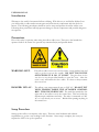
RISK AND HAZARD ANALYSIS
Two hazards involve dealing with high output voltage from wall outlets and the temperature of the
heating elements. All due diligence will be made toward properly connecting the power source with
various elements in the oven such as the power relay. Testers and users will be adequately shielded
from live high-voltage wires through proper insulation solutions. Along with this goes protection
against electrical fire and possibly electrocution. All group members possess cell phones and are
capable of using them to request medical assistance and/or other emergency pertinent authorities.
In addition to power management, users must be aware of heat damage and burns resulting from
exceedingly close contact with the heating element and/or interior of the oven itself. These injuries
can be avoided by removing the power supply and allowing the oven and heating elements to cool
to a maximum temperature of 140° F. The temperature sensor can be used to determine the
temperature or a quick wave of the hand through the air enclosed within the oven.
16
EE 449
REFLOW SOLDER OVEN
CHAPTER 3
REVISED PROJECT PLAN
The project plan has been revised concerning tasks remaining to be done beginning May 5, 2006 and
appears below in Table 3-1.
Table 3-1: Revised Reflow Solder Oven Work Breakdown
Task
No.
Task
Lead
Start
Date
End
Date
Dependant
Tasks
Prerequisite
Tasks
4.0
Plant Transfer Function
Determination
Clement
5-May
7-May
6.0, 4.1
5.0
4.1
Controller Design
Solomon
6-May
12-May
6.0
N/A
5.0
5.1
Hardware Assembly
Computer Interface
Control Software
Development
GUI Development
System Testing
System Revision
Report Compilation
Josh
Keith
4-May
6-May
12-May
12-May
5.1
6.0, 7.0
N/A
5.0
Josh
6-May
20-May
6.1
5.0, 5.1
Josh
Keith
Clement
Clement
16-May
20-May
24-May
25-May
20-May
23-May
30-May
1-Jun
7.0
7.1
8.0
N/A
6.0
6.1
7.0
All
6.0
6.1
7.0
7.1
8.0
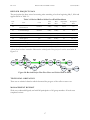
A flow chart has been created to illustrate the critical path of the project. It can be seen below in
Figure 3-8.
Figure 3-8: Revised Project Plan Flow Chart and Critical Path in Green
TECHNICAL OBSTACLES
There are no technical obstacles which obstructed the progress of the reflow toaster oven.
MANAGEMENT REPORT
Work was conducted diligently and with full participation of all group members. All tasks were
completed on time.
17
CHAPTER 4: DETAILED DESIGN
INTRODUCTION
Detailed design of the hardware and software is discussed in this chapter. The software used to
control the temperature of the oven using a digital PI controller also appears within the chapter.
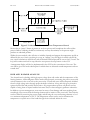
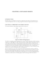
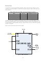
ELECTRICAL HARDWARE AND WIRING DESIGN
The electrical hardware wiring diagram appears below in Figure 4-1.
Figure 4-1: Hardware Wiring Diagram
The reflow oven utilizes several components in its control. The most important of which, and most
expensive, is a USB 1208FS I/O card. This device provides a digital output in the range of 0 and 5 V
to the solid state relay. When no voltage is placed over the relay, the switch is turned off and no
current from the wall is allowed to pass through the heating elements of the oven. Likewise, when 5
V is placed across the relay, the switch is turned on, allowing current to flow. A manual switch
allows the user to turn on and off the convection fan. For the purposes of reflow soldering, the fan
should never be turned off during the reflow soldering process.
The next component to note is the T-Type thermocouple interfaced with a K-Type conditioner.
Because of the incompatibility between these two parts, software will need to be written to correct
for this. The thermocouple and condition work together as a unit to provide analog temperature
data to the I/O card. The I/O card provides a power supply of 5 V to the unit. The thermocoupleconditioner set sends its data to the analog input of the I/O, through a buffer. The buffer is
EE 449
REFLOW SOLDER OVEN
CHAPTER 4
necessary to block outgoing current from the I/O as such current would interfere with the
functionality of the conditioner.
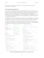
SOFTWARE PROGRAMMING
Control software programming was performed in MATLAB and can be seen in Figure 4-2. The
code consists of three major parts. The first part is the initialization of input and output channels in
addition to the various variables needed for calculations. The second and third parts occur with a
loop which terminates on command of the user. The second part involves ramping up the
temperature as fast as possible. Here there is no control of temperature. The temperature is raised to
a set “preheat” value. Since this is hardcode, it must be changed in the code itself and no option to
do so will be given in the GUI.
The third part is the actual controller. When the temperature is not rising rapidly, the controller will
be allowed to take control of the temperature. Using a discretized set of equations for the integrator
and differentiator the gains are used to calculate the necessary output in the form of a PWM.
It must also be mentioned that the software corrects for the error between the conditioner and the
thermocouple. A lookup table was created which translates a given voltage to a specific temperature.
This array must be loaded before any temperature measurements take place.
targetTemp = 0;
%temperature step size
PWMsamples = 1000;
%number of sapmles in PWM frame
startSoak = 0;
Kp = .01;
%Proportional gain
Ki = .0001;
%integration gain
Kd = 0;
dio=digitalio('mcc',0);
%initiate digital output
dline=addline(dio,0,'Out');
%add channel to output
ai=analoginput('mcc',0);
%initiate analog input
aichan=addchannel(ai, [0]); %add three channels to input
set(aichan(1), 'InputRange', [0 5]);
%near sensor
z = 0;
%integrator
w = 0;
%anti-wind up, amount output is
larger then 1
u = 0;
%output non saturation
d = 0;
%differential term
delta = 0;
%change in time
ctrlOut = 0;
%output of controller
temperature = [0 0];
%used for double buffer to plot
time = [0 0];
%used for double buffer to plot
Vin = getsample(ai);
%three column vector
error = [0 0];
%used for derivative
%set the first error, so d doesn't screw up
voltage = round(1000*getsample(ai));
i = 1;
while (voltage > lookup(i, 2)),
i = i+1;
end
rounded = (lookup(i, 2) + lookup(i + 1, 2))/2;
if (voltage - lookup(i, 2)) < rounded;
error(1) = targetTemp-lookup(i, 1);
else
error(1) = targetTemp-lookup(i + 1, 1);
end
%new figure to plot
h=figure;
hold on;
%start time
tic();
while (round(1000*getsample(ai))) < 1062
%less then
100 degrees
putvalue(dio, 1);
time(2) = time(1);
%double buffer time
time(1) = toc();
delta = time(1)-time(2);
temperature(2) = temperature(1);
%double buffer
input
voltage = round(1000*getsample(ai));
i = 1;
while (voltage > lookup(i, 2)),
i= i+1;
end
rounded = (lookup(i, 2) + lookup(i + 1, 2))/2;
if (voltage - lookup(i, 2)) < rounded
temperature(1) = lookup(i, 1);
else
temperature(1) = lookup(i + 1, 1);
end
plot([time(2), time(1)], [temperature(2), temperature(1)]);
drawnow;
%plot data as it arrives
end
putvalue(dio, 0);
targetTemp = 150;
while (round(1000*getsample(ai))) < 1660
%less then 150
degrees
time(2) = time(1);
%double buffer time
time(1) = toc();
delta = time(1)-time(2);
temperature(2) = temperature(1);
%double buffer
input
voltage = round(1000*getsample(ai));
i = 1;
while (voltage > lookup(i, 2)),
i= i+1;
end
rounded = (lookup(i, 2) + lookup(i + 1, 2))/2;
if (voltage - lookup(i, 2)) < rounded
temperature(1) = lookup(i, 1);
else
temperature(1) = lookup(i + 1, 1);
end
error(2) = error(1);
error(1) = targetTemp-temperature(1);
z = z + (Ki*error(1) - (ctrlOut-(u/PWMsamples)))*delta;
%integrate error
d = (error(1)-error(2))/delta;
ctrlOut = (Kp*error(1) + z + Kd*d);
%set output
if ctrlOut > 1
%if duty factor too
large
u = PWMsamples
%make duty factor 100%
elseif ctrlOut < 0
u = 0
else
u = round(ctrlOut*PWMsamples)
end
for count = 1:u
%for first part of PWM
putvalue(dio, 1);
%output high
Vin = getsample(ai);
%burn input data
end
for count = 1:(PWMsamples-u)%for second part of PWM
putvalue(dio, 0);
%output low
Vin = getsample(ai);
%burn input data
end
plot([time(2), time(1)], [temperature(2), temperature(1)]);
drawnow;
%plot data as it arrives
end
Figure 4-2: Simplifed MATLAB Code for Control of Reflow Oven
19
EE 449
REFLOW SOLDER OVEN
CHAPTER 4
The finalized MATLAB code can be found in the Appendix. It contains GUI code in addition to the
controller code. In the full version, there are actually fives sets of while loops. The first loop sets
heating elements to 100% on while the temperature remains more than 50 °C from the soak
temperature. Then, while the temperature is less than the soak temperature, the oven tracks a ramp.
Once time is less than 30 seconds from the soak time, the ramp changes slope. Finally, the oven
turns to full on until when the temperature comes to within 15 °C of the maximum temperature, in
which case it turns full off
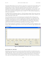
The MATLAB GUI is illustrated in Figure 4-3. The GUI functions simply. The user must enter the
soak, solder, and maximum temperatures and soak and dwell times if they so desire. Otherwise, the
defaults shown below will be used.
Once all the desired values have been entered, the user can begin the reflow solder process by
pressing the start button in the “oven” panel. Similarly, the user presses the “stop” button when
s/he wants to stop the process in order to readjust gains, the soak time, target temperature, or for
emergencies. The temperature of the oven will be displayed in the “temperature” panel and the
actual profile will appear in the large plot on the upper left of the GUI. A projected temperature
profile will be shown in red and the actual temperature profile will appear in blue.
Once the target temperature is reached, the oven will turn off and the user will be prompted to open
the door. The command will appear where the word “ready” does, below the target temperature and
soak time inputs.
Figure 4-3: MATLAB GUI for Reflow Oven
MECHANICAL DESIGN
Mechanically, the project consists of a toaster oven with a box attached to the side that houses the
control components. The box is offset from the side of the toaster oven to reduce the chances heat
will affect the circuit. The box is also vented and a fan may be attached later if cooling becomes an
issue. The I/O card is attached by Velcro to the top of the box for easy removal. A set screw is
used to prevent the thermocouple from being pulled out of the oven. Also, great care was taken to
20
EE 449
REFLOW SOLDER OVEN
CHAPTER 4
protect the wires running out of the oven and control box from being frayed. Edges are sharp so
the protective sleeves provide protection.
SAFETY REVIEW AND PROTECTION SYSTEM DESIGN
The major safety concern was the 120V A/C voltage required to power the oven. The relay is
housed inside the box to prevent people from inadvertently touching the power posts. It is not
advised to place fingers or other body parts into the box as doing so may result in severe shock or
electrocution. The oven case gets hot so it is advised not to touch the hot oven when it is in
operation.
TECHNICAL OBSTACLES
There are no technical obstacles which obstructed the progress of the reflow toaster oven during the
two weeks leading up to the fourth milestone.
MANAGEMENT REPORT
Work was conducted diligently and with full participation of all group members. All tasks were
completed on time.
21
CHAPTER 5: PROJECT IMPLEMENTATION
INTRODUCTION
This chapter will cover how our hardware was constructed and also the results of testing. From the
detailed discussion of the reflow oven, it is possible to accurately reproduce additional units. The test
results also show the limitations of the oven and optimal operating conditions in which to perform
reflow soldering.
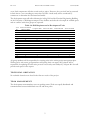
SYSTEM CONSTRUCTION
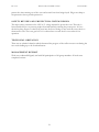
The finished reflow oven, converted from a toaster oven, appears below in Figure 5-1.
Figure 5-1: Photograph of Reflow Oven, Temperature Sensor, and I/O Card
The Black and Decker toaster oven was disassembled and the various dials and bells removed. Two
things were left intact: the convection fan switch and the safe mechanism that shuts off power to the
heating elements when the door is opened completely. The wiring for the heating elements is a
simple circuit consisting of four resistors: two resistors in series parallel with another set of two
resistors in series. Alternating current passes into one end of the resistors and exits to ground from
EE 449
REFLOW SOLDER OVEN
CHAPTER 5
the other. These two leads were taken and attached to the high voltage side of the solid-state power
relay. The power relay was also screwed down to a large heat sink for the obvious purpose of heat
dissipation. Figure 5-1 shows several wires exiting the right side of the oven into a black box bolted
to the outer case. The power relay is situated, and secured by bolts, within the box. Note that the
terminals are not protected and therefore there is a risk of shock and electrocution should any part
of the body come in contact.
The next step in preparing the oven was to prepare a series of holes to accommodate the
thermocouple temperature sensor. From Figure 5-1, it is seen that the holes were drilled in the left
side through both the outer case and inner wall of the oven and just about the highest rack slot.
Dimensionally, the hole has a diameter of 3/16 inches. The thermocouple’s wire was run behind the
oven and securely attached by three eye clips.
Within the black box, a protoboard is situated which accepts wires from the I/O card and
thermocouple. For wiring schematics, please see the previous chapter. The box itself was originally
part of a HAMM radio set and converted in a protected covering for the power relay. Four holes
were drilled into the wings allowing for the box to be screwed to the side of the oven. In order to
allow for additional cooling, spacers were added to create a one inch gap for air flow. Moreover, a
series of holes were drilled in the other end of the box to create the potential for air flow over the
heat sink. The I/O card is also set on top of the box and secured by Velcro. Tubing was used to
protect wires from contact with the oven case on the route from the protoboard to the I/O card.
The risk of heat damage to the wires, however, is very low as the oven case does not reach very high
temperatures—except on top where all the heat rises.
For aesthetic purposes, the front of the oven was stray painted black to cover up the white dial
markings for temperature and whatnot. The empty dial receptacles serve as ventilation for the
interior of the case where all the wires enter and leave. LED displays for temperature and other
indicators were considered in filling these openings but it was feared that the temperature might
damage or destroy the circuitry.
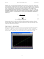
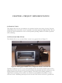
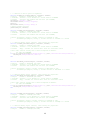
INITIAL TESTING
Initial testing was done with range of results. At first, the oven was instructed to track stem inputs
and this resulted in a very poor temperature profile often resulting in oscillations and long settling
times. Figure 5-2 is an example of one such test.
Step Response of Reflow Solder Oven
Temperature (C)
200
150
100
50
0
0
100
200
300
400
500
Time (s)
600
700
800
Figure 5-2: Response of Reflow Solder Oven to a 150 °C Step
23
900
EE 449
REFLOW SOLDER OVEN
CHAPTER 5
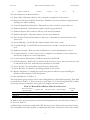
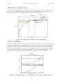
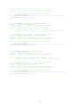
Since the purpose of the oven is to follow a temperature profile resembling a series of ramps, it was
through better to conduct tests using ramp inputs. Simulation showed a favorable response to a
ramp and the actual response to ramps was not bad. The problem with a ramp input was that the
temperature did not rise fast enough to minimize the time necessary for the reflow solder process.
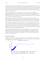
However, a ramp input was still better than a step and so it was decided to use a combination of
open and closed loop control. The open loop system was used to cause a rapid climb in temperature
and closed loop to carefully control the temperature between the use of open loop. Figure 5-3 shows
the results of this combined open/closed loop controller.
Temperature (C)
Temperature Profile of Reflow Solder Oven
225
200
175
150
125
100
75
50
25
0
0
60 120 180 240 300 360 420 480 540 600 660 720 780 840 900 9601000
Time (seconds)
Figure 5-3: Temperature Profile of Combined Open/Closed Loop Control
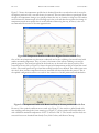
Portions of the graph in Figure 5-3 which are smooth and narrow indicate the use of closed loop
control, approximately between 150 and 400 seconds. The remainder of the plot consists of thick
blue line indicating open loop control, either “all on” or “all off.”
PERFORMANCE AND STABILITY TESTING
With the initial testing complete and a finalized controller, the limits of the system can be tested.
Several tests were done on the oven to determine the optimal setup of oven, internally. This
involved different configurations with the rack and oven tray and convection fan.
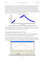
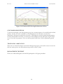
Figure 5-4 illustrates the results of turning off the convention fan. While it may seem that the
absence of the fan does not affect the profile, what is not shown is the inconsistency and unequal
distribution of heat within the oven. It is not suggested to disable the convection fan—even for the
sake of peace and quiet—while the oven is in operation and a board is being soldered.
Figure 5-4: Temperature Profile without Fan and Tray in Lowest Position
24
EE 449
REFLOW SOLDER OVEN
CHAPTER 5
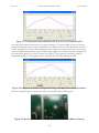
Figure 5-5 shows the temperature profile that is obtained from the oven when the rack is moved to
the highest position in the oven and the tray is removed. The convention fan was operational. From
the plot, the temperature changes very quickly without the tray as a barrier to rising heat. This makes
sense because the thermocouple is located high up in the oven and therefore registers the change in
temperature much more rapidly than it would otherwise. Removing the tray, however, is also not
recommended for reasons to become apparent later.
Figure 5-5: Temperature Profile with Rack on Highest Position without Tray
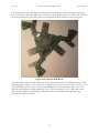
One of the most important tests that were conducted was for the soldering of an actual board with
surface mounted components. This, of course, is the intent of the reflow soldering oven and its
primary purpose. The board was placed in the metal tray on the rack in the lowest position. The
convection fan was left on. Figure 5-6 shows the projected temperature profile in red and the actual
in blue. The overall profile was good and the resulting board was not burned. The solder joints were
also nicely done and the components that were mounted still functioned after the process. This is
the optimal configuration and the one used for the extraction of model parameters and simulation.
Figure 5-6: Temperature Profile with Board and Tray in Lowest position and with Fan
However, if the optimal conditions are not used as in Figure 5-5, the result is a grilled board with
non-working parts though the joints remain good. Figure 5-7 shows another successful solder job
with a different maximum temperature of 205 °C instead of 220 °C. The boards used for these two
successful tests were obtained from Sandy Chan, Eric Carlson, and Sharon Cheung.
25
EE 449
REFLOW SOLDER OVEN
CHAPTER 5
Figure 5-7: Temperature Profile with Board and Tray in Lowest Position and Fan
Last among the various tests was that of system robustness. To test the ability to recover from an
unexpected external event, a massive disturbance was added to the oven. The disturbance consisted
in fully opening the oven door and introducing a large volume of outside air into the oven cavity by
means of rapid exhalation from a pair of human lungs. Figure 5-8 records this event at roughly 190
seconds into the process at a time of closed loop control. The system recovered fully from the
disturbance though it is still suggested not to perform this test while soldering a board.
Figure 5-8: Temperature Profile with Optimal Settings and Major Door-Open Disturbance
The two boards in Figure 5-9 show the results of successful reflow soldering runs.
Figure 5-9: Boards which have Successfully Endured the Process of Reflow Soldering
26
EE 449
REFLOW SOLDER OVEN
CHAPTER 5
For the customer demo, Nils Napp working for Professor Klavins in the Self Organizing Systems
Lab volunteered to allow the build team to solder one of his boards. Figure 5-10 shows the soldered
board and components. The solder joints are comparable to those done in a professional shop.
Figure 5-10: Finished PCB Board
To further improve the amount of data that can be gathered from the GUI, additional plots for the
PWM signal were added as seen in Figure 5-11. Open loop control consists of either “all on” or “all
off.” The PWM signal for such a case is green and appears between 100 and 0 on the y-axis. The
PWM is a percentage with 100% indicating “all on” and 0% meaning “all off.” When the system
enters closed loop mode, the PWM plot turns black. The default maximum temperature was
changed from 220 °C to 205 °C.
27
EE 449
REFLOW SOLDER OVEN
CHAPTER 5
Figure 5-11: Finalized GUI Showing Performance of Oven
CUSTOMER RECEPTION
To the best knowledge of the development group, the customer appears to be satisfied with the final
product. Actually, the word “satisfied” is an understatement, the customer is ecstatic. Not
surprisingly, other persons within the University of Washington’s electrical engineering department
are more excited about the reflow oven than even the intended customer and express a great desire
to use it for their own purposes. The oven will be placed in Bill Lynes’ lab for department general
use.
TECHNICAL OBSTACLES
There were no technical obstacles encountered during the progress of the reflow toaster oven in the
final two weeks prior to the fifth milestone report due on June 2, 2006.
MANAGEMENT REPORT
Work was conducted diligently and with full participation of all group members.
28
APPENDIX
MATLAB CODE
The following is the full MATLAB code for the GUI and control of the reflow soldering oven. The
MATLAB figure for the GUI appears in Chapter 4 in Figure 4-3.
function varargout = EasySolder(varargin)
% EASYSOLDER M-file for EasySolder.fig
%
EASYSOLDER, by itself, creates a new EASYSOLDER or raises the existing
%
singleton*.
%
%
H = EASYSOLDER returns the handle to a new EASYSOLDER or the handle to
%
the existing singleton*.
%
%
EASYSOLDER('CALLBACK',hObject,eventData,handles,...) calls the local
%
function named CALLBACK in EASYSOLDER.M with the given input arguments.
%
%
EASYSOLDER('Property','Value',...) creates a new EASYSOLDER or raises the
%
existing singleton*. Starting from the left, property value pairs are
%
applied to the GUI before EasySolder_OpeningFunction gets called. An
%
unrecognized property name or invalid value makes property application
%
stop. All inputs are passed to EasySolder_OpeningFcn via varargin.
%
%
*See GUI Options on GUIDE's Tools menu. Choose "GUI allows only one
%
instance to run (singleton)".
%
% See also: GUIDE, GUIDATA, GUIHANDLES
% Edit the above text to modify the response to help EasySolder
% Last Modified by GUIDE v2.5 21-May-2006 17:37:03
% Begin initialization code - DO NOT EDIT
gui_Singleton = 1;
gui_State = struct('gui_Name',
mfilename, ...
'gui_Singleton', gui_Singleton, ...
'gui_OpeningFcn', @EasySolder_OpeningFcn, ...
'gui_OutputFcn', @EasySolder_OutputFcn, ...
'gui_LayoutFcn', [] , ...
'gui_Callback',
[]);
if nargin && ischar(varargin{1})
gui_State.gui_Callback = str2func(varargin{1});
end
if nargout
[varargout{1:nargout}] = gui_mainfcn(gui_State, varargin{:});
else
gui_mainfcn(gui_State, varargin{:});
end
% End initialization code - DO NOT EDIT
% --- Executes just before EasySolder is made visible.
function EasySolder_OpeningFcn(hObject, eventdata, handles, varargin)
% This function has no output args, see OutputFcn.
% hObject
handle to figure
% eventdata reserved - to be defined in a future version of MATLAB
% handles
structure with handles and user data (see GUIDATA)
% varargin
command line arguments to EasySolder (see VARARGIN)
% Choose default command line output for EasySolder
handles.output = hObject;
set(handles.startButton,'Userdata', false);
set(handles.stopButton,'Userdata', false);
% Update handles structure
guidata(hObject, handles);
% UIWAIT makes EasySolder wait for user response (see UIRESUME)
% uiwait(handles.figure1);
% --- Outputs from this function are returned to the command line.
function varargout = EasySolder_OutputFcn(hObject, eventdata, handles)
% varargout cell array for returning output args (see VARARGOUT);
% hObject
handle to figure
% eventdata reserved - to be defined in a future version of MATLAB
% handles
structure with handles and user data (see GUIDATA)
% Get default command line output from handles structure
varargout{1} = handles.output;
% --- Executes on button press in startButton.
function startButton_Callback(hObject, eventdata, handles)
% hObject
handle to startButton (see GCBO)
% eventdata reserved - to be defined in a future version of MATLAB
% handles
structure with handles and user data (see GUIDATA)
set(handles.stopButton, 'UserData', false);
lookup =
[0
1
2
3
4
5
6
7
8
9
10
11
12
13
14
15
16
17
18
19
20
21
22
23
24
25
26
27
28
29
30
31
32
33
3
12
22
32
41
51
61
70
80
90
100
109
119
129
139
148
158
168
178
188
198
208
218
228
238
248
258
268
278
288
298
309
319
329
30
34
35
36
37
38
39
40
41
42
43
44
45
46
47
48
49
50
51
52
53
54
55
56
57
58
59
60
61
62
63
64
65
66
67
68
69
70
71
72
73
74
75
76
77
78
79
80
81
82
83
84
85
86
87
88
89
90
91
92
93
94
95
96
97
98
99
100
101
102
103
104
105
339
350
360
370
380
391
401
411
422
433
443
454
464
475
485
496
506
517
528
538
549
559
570
581
591
602
613
624
635
646
656
667
678
689
700
711
722
733
744
753
766
777
788
799
810
821
833
844
855
866
878
889
900
912
923
934
946
957
969
980
991
1003
1014
1026
1037
1049
1061
1072
1084
1095
1107
1118
31
106
107
108
109
110
111
112
113
114
115
116
117
118
119
120
121
122
123
124
125
126
127
128
129
130
131
132
133
134
135
136
137
138
139
140
141
142
143
144
145
146
147
148
149
150
151
152
153
154
155
156
157
158
159
160
161
162
163
164
165
166
167
168
169
170
171
172
173
174
175
176
177
1130
1142
1154
1165
1177
1189
1201
1213
1224
1236
1248
1260
1272
1284
1296
1308
1320
1332
1344
1355
1368
1379
1392
1404
1416
1428
1440
1452
1464
1476
1488
1501
1513
1525
1537
1550
1562
1574
1587
1599
1611
1624
1636
1649
1661
1673
1686
1698
1711
1723
1736
1749
1761
1774
1785
1798
1810
1822
1835
1848
1860
1873
1886
1898
1911
1923
1936
1949
1962
1974
1987
2000
32
178
179
180
181
182
183
184
185
186
187
188
189
190
191
192
193
194
195
196
197
198
199
200
201
202
203
204
205
206
207
208
209
210
211
212
213
214
215
216
217
218
219
220
221
222
223
224
225
226
227
228
229
230
231
232
233
234
235
236
237
238
239
240
241
242
243
244
245
246
247
248
249
2013
2026
2040
2052
2065
2078
2091
2104
2117
2130
2143
2156
2169
2182
2195
2208
2221
2234
2247
2260
2274
2287
2299
2312
2326
2339
2352
2365
2378
2392
2405
2418
2431
2444
2458
2471
2484
2498
2511
2525
2538
2551
2569
2583
2596
2609
2623
2637
2650
2664
2677
2691
2704
2718
2732
2745
2759
2772
2786
2800
2814
2828
2837
2851
2864
2878
2892
2905
2919
2933
2947
2960
33
250
251
252
253
254
255
256
257
258
259
260
261
262
263
264
265
266
267
268
269
270
271
272
273
274
275
276
277
278
279
280
281
282
283
284
285
286
287
288
289
290
291
292
293
294
295
296
297
298
299
300
301
302
303
304
305
306
307
308
309
310
311
312
313
314
315
316
317
318
319
320
321
2974
2988
3002
3016
3029
3043
3057
3071
3085
3099
3114
3128
3142
3156
3170
3184
3197
3212
3226
3240
3254
3268
3282
3296
3310
3324
3338
3352
3367
3381
3398
3412
3426
3440
3455
3469
3483
3497
3512
3526
3540
3555
3569
3583
3598
3612
3626
3640
3655
3670
3679
3694
3708
3722
3737
3751
3765
3780
3794
3809
3823
3838
3852
3867
3881
3896
3910
3925
3939
3953
3972
3986
34
322
323
324
325
326
327
328
329
330
331
332
333
334
335
336
337
338
339
340
341
342
343
344
345
346
347
348
349
350
351
352
353
354
355
356
357
358
359
360
361
362
363
364
365
366
367
368
369
370
371
372
373
374
375
376
377
378
379
380
381
382
383
384
385
386
387
388
389
390
391
392
393
4001
4016
4030
4045
4060
4074
4089
4104
4119
4133
4148
4163
4177
4192
4207
4222
4237
4251
4264
4279
4294
4309
4323
4338
4353
4368
4383
4398
4413
4428
4442
4457
4472
4487
4502
4517
4532
4547
4560
4575
4590
4605
4620
4635
4650
4665
4680
4695
4710
4725
4740
4756
4771
4786
4801
4816
4831
4846
4857
4872
4887
4902
4917
4932
4947
4963
4978
4993
5008
5023
5038
5054
35
394
395
396
397
398
399
400
5069
5084
5099
5115
5130
5145
5160];
%editable variables
soakTemp = str2double(get(handles.soakTemp,'String'));
soakTime = str2double(get(handles.soakTime,'String'));
maxTemp = str2double(get(handles.maxTemp,'String'));
dwellTime = str2double(get(handles.dwellTime,'String'));
solderMeltTemp = str2double(get(handles.solderTemp,'String'));
%system variables
targetTemp = 0;
startSoak = 0;
startDwell = 0;
openDoor = 0;
stop = false;
%controller parameters
Kp = .01;
Ki = .0001;
PWMsamples = 1000;
%degree C
%in seconds
%degree C
%in seconds
%degree C
%input to controller
%time soakTemp is reached
%time solderMeltTemp is reached
%flag to open door for cool off
%Proportional gain
%integration gain
%number of sapmles in PWM frame
%I/O card initiation
dio=digitalio('mcc',0);
dline=addline(dio,0,'Out');
ai=analoginput('mcc',0);
aichan=addchannel(ai, [0]);
set(aichan(1), 'InputRange', [0 5]);
%initiate digital output
%add channel to output
%initiate analog input
%add channel to input
%set voltage range for input
%system variable initialization
z = 0;
%integrator
w = 0;
%anti-wind up, amount output is larger then 1
u = 0;
%output non saturation
delta = 0;
%change in time
ctrlOut = 0;
%output of controller
temperature = [0 0];
%used for double buffer to plot
time = [0 0];
%used for double buffer to plot
error = 0;
%used for derivative
%new figure to plot
hold off;
%start time
%plot trajectory
p0 = [0;30];
p1 = [30;30];
p2 = [2*(soakTemp-30)+30;soakTemp];
p3 = [p2(1)+soakTime;solderMeltTemp];
p4 = [p3(1)+2*(maxTemp-solderMeltTemp);maxTemp];
p5 = [p3(1)+dwellTime-30;maxTemp];
p6 = [p5(1)+maxTemp*2;30];
traj = [p0 p1 p2 p3 p4 p5 p6];
plot(traj(1,:), traj(2,:), 'r');
hold on;
tic();
set(handles.status,'String','Running');
%run to soakTemp - 50
while (temperature(1)) < soakTemp-50 & (stop == false)
%more then 50 degrees from soakTemp
putvalue(dio, 1);
%always on
time(2) = time(1);
%double buffer time
time(1) = toc();
temperature(2) = temperature(1);
%double buffer input
voltage = round(1000*getsample(ai));%voltage in
%look up temperature
36
i = 1;
while (voltage > lookup(i, 2)),
i= i+1;
end
rounded = (lookup(i, 2) + lookup(i + 1, 2))/2;
if (voltage - lookup(i, 2)) < rounded
temperature(1) = lookup(i, 1);
else
temperature(1) = lookup(i + 1, 1);
end
set(handles.tempC,'String',num2str(temperature(1)));%Display temp. (C)
farenheit = round((9/5)*temperature(1) + 32);
%Convert C to F
set(handles.tempF,'String',num2str(farenheit));
%Display temp. (F)
%plot data as it arrives
plot([time(2), time(1)], [temperature(2), temperature(1)]);
plot(time(1), 100, 'g');
plot(0, 0, 'k');
legend('Projected Profile', 'Actual Profile', 'Open Loop PWM (%)', 'Closed Loop PWM (%)');
drawnow;
stop = get(handles.stopButton,'Userdata');
end
putvalue(dio, 0);
targetTemp = soakTemp;
%controll to soakTemp
uold = 100;
while (temperature(1) < soakTemp) & (stop == false)
%less then soakTemp
time(2) = time(1);
%double buffer time
time(1) = toc();
delta = time(1)-time(2);
temperature(2) = temperature(1);
%double buffer input
voltage = round(1000*getsample(ai));%voltage in
%look up temperature
i = 1;
while (voltage > lookup(i, 2)),
i= i+1;
end
rounded = (lookup(i, 2) + lookup(i + 1, 2))/2;
if (voltage - lookup(i, 2)) < rounded
temperature(1) = lookup(i, 1);
else
temperature(1) = lookup(i + 1, 1);
end
set(handles.tempC,'String',num2str(temperature(1)));%Display temp. (C)
farenheit = round((9/5)*temperature(1) + 32);
%Convert C to F
set(handles.tempF,'String',num2str(farenheit));
%Display temp. (F)
error = targetTemp-temperature(1); %compute error
z = z + (Ki*error - (ctrlOut-(u/PWMsamples)))*delta;
ctrlOut = (Kp*error + z );
%compute output
if ctrlOut > 1
u = PWMsamples
elseif ctrlOut < 0
u = 0;
else
u = round(ctrlOut*PWMsamples);
end
for count = 1:u
putvalue(dio, 1);
getsample(ai);
end
%integrate error
%if duty factor too large
%make duty factor 100%
%if duty too small
%make duty 0%
%otherwise
%duty stays same
%for first part of PWM
%output high
%burn input data
for count = 1:(PWMsamples-u)%for second part of PWM
37
putvalue(dio, 0);
getsample(ai);
%output low
%burn input data
end
plot([time(2), time(1)], [temperature(2), temperature(1)]);
plot([time(2), time(1)], [uold, u/10], 'k');
drawnow;
%plot data as it arrives
stop = get(handles.stopButton,'Userdata');
uold = u/10;
end
startSoak = toc;
targetTemp = solderMeltTemp;
%ramp up to
while toc <
time(2)
time(1)
delta =
solder melt temp
(startSoak+soakTime-60) & (stop == false) %for thirty seconds less then soakTime
= time(1);
%double buffer time
= toc();
time(1)-time(2);
temperature(2) = temperature(1);%double buffer input
voltage = round(1000*getsample(ai));
%look up temperature
i = 1;
while (voltage > lookup(i, 2)),
i= i+1;
end
rounded = (lookup(i, 2) + lookup(i + 1, 2))/2;
if (voltage - lookup(i, 2)) < rounded
temperature(1) = lookup(i, 1);
else
temperature(1) = lookup(i + 1, 1);
end
set(handles.tempC,'String',num2str(temperature(1)));%Display temp. (C)
farenheit = round((9/5)*temperature(1) + 32);
%Convert C to F
set(handles.tempF,'String',num2str(farenheit));
%Display temp. (F)
error = targetTemp-temperature(1); %compute error
z = z + (Ki*error - (ctrlOut-(u/PWMsamples)))*delta;
ctrlOut = (Kp*error + z );
%compute output
if ctrlOut > 1
u = PWMsamples
elseif ctrlOut < 0
u = 0;
else
u = round(ctrlOut*PWMsamples);
end
for count = 1:u
putvalue(dio, 1);
getsample(ai);
end
%integrate error
%if duty factor too large
%make duty factor 100%
%if duty too small
%make duty 0%
%otherwise
%duty stays same
%for first part of PWM
%output high
%burn input data
for count = 1:(PWMsamples-u)%for second part of PWM
putvalue(dio, 0);
%output low
getsample(ai);
%burn input data
end
plot([time(2), time(1)], [temperature(2), temperature(1)]);
plot([time(2), time(1)], [uold, u/10], 'k');
drawnow;
%plot data as it arrives
stop = get(handles.stopButton,'Userdata');
uold = u/10;
end
%upto 15 degrees from max
while ((temperature(1)<maxTemp-10)&(openDoor == 0)) & (stop == false)
putvalue(dio, 1);
%all on
38
if((startDwell == 0)&(temperature(1)>=solderMeltTemp))
%if above melt temp
startDwell = toc;
%time at melt temp
elseif ((startDwell ~= 0)&(time(1)>(startDwell+dwellTime))) %if past dwell time
openDoor = 1;
%open door
set(handles.status,'String','Open Door');
end
time(2) = time(1);
time(1) = toc();
delta = time(1)-time(2);
%double buffer time
temperature(2) = temperature(1);
%double buffer input
voltage = round(1000*getsample(ai));
%look up temperature
i = 1;
while (voltage > lookup(i, 2)),
i= i+1;
end
rounded = (lookup(i, 2) + lookup(i + 1, 2))/2;
if (voltage - lookup(i, 2)) < rounded
temperature(1) = lookup(i, 1);
else
temperature(1) = lookup(i + 1, 1);
end
set(handles.tempC,'String',num2str(temperature(1)));%Display temp. (C)
farenheit = round((9/5)*temperature(1) + 32);
%Convert C to F
set(handles.tempF,'String',num2str(farenheit));
%Display temp. (F)
plot([time(2), time(1)], [temperature(2), temperature(1)]);
plot(time(1), 100, 'g');
drawnow;
%plot data as it arrives
stop = get(handles.stopButton,'Userdata');
end
%reflow done, open cool down cycle
while (stop == false) %more then 50 degrees
putvalue(dio, 0);
%all off
if ((startDwell ~= 0)&(time(1)>(startDwell+dwellTime))) %if past dwell time
openDoor = 1;
%open door
set(handles.status,'String','Open Door');
end
time(2) = time(1);
time(1) = toc();
delta = time(1)-time(2);
%double buffer time
temperature(2) = temperature(1);
%double buffer input
voltage = round(1000*getsample(ai));
%lookup temperature
i = 1;
while (voltage > lookup(i, 2)),
i= i+1;
end
rounded = (lookup(i, 2) + lookup(i + 1, 2))/2;
if (voltage - lookup(i, 2)) < rounded
temperature(1) = lookup(i, 1);
else
temperature(1) = lookup(i + 1, 1);
end
set(handles.tempC,'String',num2str(temperature(1)));%Display temp. (C)
farenheit = round((9/5)*temperature(1) + 32);
%Convert C to F
set(handles.tempF,'String',num2str(farenheit));
%Display temp. (F)
plot([time(2), time(1)], [temperature(2), temperature(1)]);
plot(time(1), 0, 'g');
drawnow;
%plot data as it arrives
stop = get(handles.stopButton,'Userdata');
end
39
% --- Executes on button press in stopButton.
function stopButton_Callback(hObject, eventdata, handles)
% hObject
handle to stopButton (see GCBO)
% eventdata reserved - to be defined in a future version of MATLAB
% handles
structure with handles and user data (see GUIDATA)
set(hObject,'Userdata', true);
set(handles.status,'String','Stopped');
pause(5);
set(handles.status,'String','Ready!');
% Update handles structure
guidata(hObject, handles);
function soakTime_Callback(hObject, eventdata, handles)
% hObject
handle to soakTime (see GCBO)
% eventdata reserved - to be defined in a future version of MATLAB
% handles
structure with handles and user data (see GUIDATA)
% Hints: get(hObject,'String') returns contents of soakTime as text
%
str2double(get(hObject,'String')) returns contents of soakTime as a double
% --- Executes during object creation, after setting all properties.
function soakTime_CreateFcn(hObject, eventdata, handles)
% hObject
handle to soakTime (see GCBO)
% eventdata reserved - to be defined in a future version of MATLAB
% handles
empty - handles not created until after all CreateFcns called
% Hint: edit controls usually have a white background on Windows.
%
See ISPC and COMPUTER.
if ispc && isequal(get(hObject,'BackgroundColor'), get(0,'defaultUicontrolBackgroundColor'))
set(hObject,'BackgroundColor','white');
end
function dwellTime_Callback(hObject, eventdata, handles)
% hObject
handle to dwellTime (see GCBO)
% eventdata reserved - to be defined in a future version of MATLAB
% handles
structure with handles and user data (see GUIDATA)
% Hints: get(hObject,'String') returns contents of dwellTime as text
%
str2double(get(hObject,'String')) returns contents of dwellTime as a double
% --- Executes during object creation, after setting all properties.
function dwellTime_CreateFcn(hObject, eventdata, handles)
% hObject
handle to dwellTime (see GCBO)
% eventdata reserved - to be defined in a future version of MATLAB
% handles
empty - handles not created until after all CreateFcns called
% Hint: edit controls usually have a white background on Windows.
%
See ISPC and COMPUTER.
if ispc && isequal(get(hObject,'BackgroundColor'), get(0,'defaultUicontrolBackgroundColor'))
set(hObject,'BackgroundColor','white');
end
function soakTemp_Callback(hObject, eventdata, handles)
% hObject
handle to soakTemp (see GCBO)
% eventdata reserved - to be defined in a future version of MATLAB
% handles
structure with handles and user data (see GUIDATA)
% Hints: get(hObject,'String') returns contents of soakTemp as text
%
str2double(get(hObject,'String')) returns contents of soakTemp as a double
% --- Executes during object creation, after setting all properties.
function soakTemp_CreateFcn(hObject, eventdata, handles)
% hObject
handle to soakTemp (see GCBO)
40
% eventdata
% handles
reserved - to be defined in a future version of MATLAB
empty - handles not created until after all CreateFcns called
% Hint: edit controls usually have a white background on Windows.
%
See ISPC and COMPUTER.
if ispc && isequal(get(hObject,'BackgroundColor'), get(0,'defaultUicontrolBackgroundColor'))
set(hObject,'BackgroundColor','white');
end
function solderTemp_Callback(hObject, eventdata, handles)
% hObject
handle to solderTemp (see GCBO)
% eventdata reserved - to be defined in a future version of MATLAB
% handles
structure with handles and user data (see GUIDATA)
% Hints: get(hObject,'String') returns contents of solderTemp as text
%
str2double(get(hObject,'String')) returns contents of solderTemp as a double
% --- Executes during object creation, after setting all properties.
function solderTemp_CreateFcn(hObject, eventdata, handles)
% hObject
handle to solderTemp (see GCBO)
% eventdata reserved - to be defined in a future version of MATLAB
% handles
empty - handles not created until after all CreateFcns called
% Hint: edit controls usually have a white background on Windows.
%
See ISPC and COMPUTER.
if ispc && isequal(get(hObject,'BackgroundColor'), get(0,'defaultUicontrolBackgroundColor'))
set(hObject,'BackgroundColor','white');
end
function maxTemp_Callback(hObject, eventdata, handles)
% hObject
handle to maxTemp (see GCBO)
% eventdata reserved - to be defined in a future version of MATLAB
% handles
structure with handles and user data (see GUIDATA)
% Hints: get(hObject,'String') returns contents of maxTemp as text
%
str2double(get(hObject,'String')) returns contents of maxTemp as a double
% --- Executes during object creation, after setting all properties.
function maxTemp_CreateFcn(hObject, eventdata, handles)
% hObject
handle to maxTemp (see GCBO)
% eventdata reserved - to be defined in a future version of MATLAB
% handles
empty - handles not created until after all CreateFcns called
% Hint: edit controls usually have a white background on Windows.
%
See ISPC and COMPUTER.
if ispc && isequal(get(hObject,'BackgroundColor'), get(0,'defaultUicontrolBackgroundColor'))
set(hObject,'BackgroundColor','white');
end
41
USER MANUAL
Introduction
Welcome to the world of automated reflow soldering. With this easy to use Reflow Solder Oven
you will be able to solder surface mount parts and other circuit components with the click of a
button. The following procedures should be used to setup and operate the reflow solder oven.
Following these procedures will help prevent damage to circuit components and possible dangers to
the operator.
Precautions
First of all, safety is a priority when using the reflow solder oven. There are a few hazards the
operator needs to be aware of to prevent any unwanted injury and possible death.
WARNING: HOT –
The reflow solder oven is an oven. By nature, ovens produce heat and
tend to get hot even on the outside. DO NOT TOUCH THE
OVEN WHEN IT IS ON. IT IS HOT. The glass door is also
very hot so use the provided handle to open the oven. After the
oven is on it will remain hot for a while. It is best to always assume
the oven is hot.
DANGER: 120V AC – The reflow oven components all run on 120V AC. DO NOT PUT
YOUR FINGERS INSIDE THE ATTACHED CONTROL
BOX. THIS COULD KILL YOU. The small box attached to the
right side of the reflow oven is the control box. This box holds the
thermocouple conditioner and relay. The relay is connected to 120V
AC so it can shock you or worse. Refrain from putting anything in
the control box.
Setup Procedure
Setting up the reflow oven requires a few steps. There are some hardware and software
requirements to get the oven working for the first time. Once setup is complete, the oven just
requires the GUI to be up for operation.
42
Hardware Setup
To operate the oven it must be hooked up properly. First, connect the wires coming out of the
control box to the USB 1208FS I/O card if it is not already connected. Table 1 shows what each
wire connection.
Table 1: Wires from Control Box and Corresponding I/O card Port
Wire
Wire Color
USB 1208FS I/O Card Port
Thermocouple Conditioner Out
Relay +
Relay Ground
+5V
Yellow
White/Black Stripe
White
Black
Gray
A0
D0
DGnd
DGnd
+5V
In addition to the above connections, ports DGnd, AGnd, and A1 on the USB 1208FS I/O card
need to be connected together. The I/O card is then connected to the PC using a USB cable. See
the card manual if you have problems setting up. Plug the reflow oven into a wall outlet to provide
the 120V AC required.
Figure 1 shows all connections that need to be made.
Figure 1: USB Connections
43
Software Setup
To use the reflow oven you need to have InstaCal and Matlab software installed on your PC.
Once these are installed you must also make sure you have the most up to date mwmcc.ini file
installed in you C:\Program_Files\Matlab\Toolbox\DAQ\DAQ\Private\ directory. We have
included the mwmcc.ini we used for this project.
Copy the files for the oven GUI to the PC. The files are called:
EasySolder.fig
EasySolder.m
InstaCal
If your Plug and Play board has been properly detected by the system, InstaCal will display a
Board Detection dialog box listing the board you are installing and any boards that have been detected in the
system. Once installed, the properties (configuration) of the board may be changed by double clicking on the
board name. Test to make sure the I/O card is working properly by flashing the LED.
Matlab
You can start the oven GUI by double clicking on the EasySolder.m file.
EasySolder GUI
Figure 2: The Easy Solder GUI
The GUI will allow you to set profile characteristics such as Soak Time, Dwell Time, Soak Temp,
Solder Temp and Max Temp. It will start with default values that have been tested and work. There
are no limits to the values so some values will create a messed up looking profile. If you change the
44
profile settings, first hit start, then stop, to view the profile you created. If it looks like the profile
that you desire then proceed; otherwise enter new values and try again. You can always restart the
program to get the defaults back.
Once you have a profile you are ready to put your PCB and pasted components on the tray and
insert the tray into the oven.
Turn on the oven convection fan using the switch on the front of the oven. This will help to create
an even temperature in the oven and help with cooling during the ramp down cycle. The fan is loud
so you have an audible clue that the oven is working.
The GUI will display “Ready!” in the lower text box. Clicking the “Start” button will start the
reflow process. Clicking “Stop” at anytime will stop the process. While the process is running:
“Running…” will appear in the lower text box. Once the profile reaches the end of the solder cycle
you will be prompted to “Open Door” (lower text box). At this time open the oven door to help
with cooling.
The plot will display the desired profile in red, the actual temperature in blue, and the control signal
in green/black (open-loop/closed-loop). The current temperature readings in degrees C and F are
found in the lower right corner.
Modification to the Matlab file can be made to change how the oven operate and how the GUI
works. It is recommended to make a backup file before changing anything. Also the files are
currently set to read-only to prevent accidental modification.
Turn off the fan when done.
Caring for Your Reflow Solder Oven
The Reflow Solder Oven needs love to function properly. Taking proper care of your oven will help
work reliably for many years.
To clean the oven use soap and water on a towel. This will get those nasty finger prints off the glass.
When picking up the oven, DO NOT pick it up by the thermocouple or the control box. The
thermocouple it somewhat fragile and may bend or break. The control box is head on by some
small-headed bolts that may rip out of the side of the oven if too much weight is being supported.
To pick up the oven, put your hands on the oven. Be careful that the oven is not hot. Bend at the
knees and all is good.
Hopefully you will have many good years of reflow fun with your new oven.
45
ACKNOWLEDGEMENTS
EE 449 DESIGN OF AUTOMATIC CONTROL SYSTEMS
Dr. Blake Hannaford, Professor of Electrical Engineering
Mr. Phil Roan, Electrical Engineering Teaching Assistant
Mr. Eric Carlson, Senior of Electrical Engineering
Ms. Sandy Chan, Senior of Electrical Engineering
Ms. Sharon Cheung, Senior of Electrical Engineering
DEPARTMENT OF ELECTRICAL ENGINEERING
Dr. Eric Klavins, Professor of Electrical Engineering
Dr. Tim Chinowsky, Professor of Electrical Engineering
Dr. Babak Parviz, Professor of Electrical Engineering
Mr. Nils Napp, Graduate Student of Electrical Engineering
Mr. Chris Morris, Graduate Fellow of Electrical Engineering
AUTHORS
SOLOMON GEBRE
Solomon Gebre is a Senior in Electrical Engineering in the University of Washington
College of Engineering. He is specializing in power and control systems. When
Solomon is not studying, taking tests, or working on lab he serves as husband and
father. He likes Subway sandwiches.
KEITH JOHNSON
Keith Johnson is a Senior in Electrical Engineering in the University of Washington
College of Engineering. In addition to attending school full-time, he works as a full-time
intern at Boeing testing the 787. Upon graduating, Keith will work for Boeing as an
Engineer. His specialty is in controls. During the length of the design and construction
of the reflow oven he managed to survive off no more than four hours of sleep a day.
WILLIAM JOSH RUSSELL
Josh Russell is a Senior in Electrical Engineering in the University of Washington
College of Engineering. He will be attending the University of California at Santa
Barbara in pursuit of a Doctorate in Electrical Engineering. Josh enjoys sailing, flying,
motorcycles, wind surfing, and a plethora of other pastimes in his limited free time and
acts as Commodore for the Washington Yacht Club. His specialty is in controls
engineering and he possesses a minor in mathematics. Josh has big guns.
CLEMENT SUN
Clement Sung-Jay Sun is the son of Lionel Lo-Jung Sun, PE, and grandson of HsiangPei Sun. He is descended from Tien Shu, Duke of Lo-An but is a native of Washington
State. A senior in Electrical Engineering at the University of Washington, Clement will
continue his attendance at the University in pursuit of a Masters degree. His
specialization is in controls and digital signal processing and he has a strong interest in
chemistry and biology.