1
MELSEC iQ-F FX5 Simple Motion Module
User's Manual (Advanced Synchronous Control)
-FX5-40SSC-S
SAFETY PRECAUTIONS
(Read these precautions before use.)
Before using this product, please read this manual and the relevant manuals introduced in this manual carefully and pay full
attention to safety in order to handle the product correctly.
This manual classifies the safety precautions into two categories: [
WARNING] and [
CAUTION].
WARNING
Indicates that incorrect handling may cause hazardous conditions, resulting in
death or severe injury.
CAUTION
Indicates that incorrect handling may cause hazardous conditions, resulting in
minor or moderate injury or property damage.
Depending on the circumstances, procedures indicated by [
CAUTION] may also cause severe injury.
It is important to follow all precautions for personal safety.
Store this manual in a safe place so that it can be read whenever necessary. Always forward it to the end user.
[DESIGN PRECAUTIONS]
WARNING
● Make sure to set up the following safety circuits outside the PLC to ensure safe system operation
even during external power supply problems or PLC failure. Otherwise, malfunctions may cause
serious accidents.
- Most importantly, set up the following: an emergency stop circuit, a protection circuit, an interlock
circuit for opposite movements (such as forward vs. reverse rotation), and an interlock circuit to
prevent damage to the equipment at the upper and lower positioning limits.
- Note that when the CPU module detects an error, such as a watchdog timer error, during selfdiagnosis, all outputs are turned off. Also, when an error that cannot be detected by the CPU
module occurs in an input/output control block, output control may be disabled. External circuits
and mechanisms should be designed to ensure safe machine operation in such a case.
- Note that the output current of the 24 V DC service power supply varies depending on the model
and the absence/presence of extension modules. If an overload occurs, the voltage automatically
drops, inputs in the PLC are disabled, and all outputs are turned off. External circuits and
mechanisms should be designed to ensure safe machine operation in such a case.
- Note that when an error occurs in a relay, triac or transistor of an output circuit, the output might
stay on or off. For output signals that may lead to serious accidents, external circuits and
mechanisms should be designed to ensure safe machine operation.
● Construct an interlock circuit in the program to ensure safe operation for the whole system when
executing control (for data change) of the PLC in operation.
Read the manual thoroughly and ensure complete safety before executing other controls (for program
change, parameter change, forced output and operation status change) of the PLC in operation.
Otherwise, the machine may be damaged and accidents may occur due to erroneous operations.
● In an output circuit, when a load current exceeding the current rating or an overcurrent caused by a
load short-circuit flows for a long time, it may cause smoke and fire. To prevent this, configure an
external safety circuit, such as a fuse.
● For the operating status of each station after a communication failure of the network, refer to relevant
manuals for the network. Incorrect output or malfunction may result in an accident.
1
[DESIGN PRECAUTIONS]
CAUTION
● When an inductive load such as a lamp, heater, or solenoid valve is controlled, a large current
(approximately ten times greater than normal) may flow when the output is turned from off to on. Take
proper measures so that the flowing current does not exceed the value corresponding to the
maximum load specification of the resistance load.
● After the CPU module is powered on or is reset, the time taken to enter the RUN status varies
depending on the system configuration, parameter settings, and/or program size.
Design circuits so that the entire system will always operate safely, regardless of this variation in time.
● Simultaneously turn on and off the power supplies of the CPU module and extension modules.
● If a long-time power failure or an abnormal voltage drop occurs, the PLC stops, and output is turned
off. When the power supply is restored, it will automatically restart (when the RUN/STOP/RESET
switch is on RUN).
[INSTALLATION PRECAUTIONS]
WARNING
● Make sure to cut off all phases of the power supply externally before attempting installation or wiring
work. Failure to do so may cause electric shock or damage to the product.
● Use the product within the generic environment specifications described in the generic specifications
of the following manual.
MELSEC iQ-F FX5 User's Manual (Hardware)
Never use the product in areas with excessive dust, oily smoke, conductive dusts, corrosive gas (salt
air, Cl2, H2S, SO2 or NO2), flammable gas, vibration or impacts, or expose it to high temperature,
condensation, or rain and wind.
If the product is used in such conditions, electric shock, fire, malfunctions, deterioration or damage
may occur.
2
[INSTALLATION PRECAUTIONS]
CAUTION
● Do not touch the conductive parts of the product directly. Doing so may cause device failures or
malfunctions.
● When drilling screw holes or wiring, make sure that cutting and wiring debris do not enter the
ventilation slits of the PLC. Failure to do so may cause fire, equipment failures or malfunctions.
● For product supplied together with a dust proof sheet, the sheet should be affixed to the ventilation
slits before the installation and wiring work in order to block foreign objects such as cutting and wiring
debris.
However, when the installation work is completed, make sure to remove the sheet to provide
adequate ventilation. Failure to do so may cause fire, equipment failures or malfunctions.
● Install the product on a flat surface. If the mounting surface is rough, undue force will be applied to the
PC board, thereby causing nonconformities.
● Install the product securely using a DIN rail or mounting screws.
● Connect the expansion board and expansion adapter securely to their designated connectors. Loose
connections may cause malfunctions.
● Make sure to affix the expansion board with tapping screws. Tightening torque should follow the
specifications in the manual. If the screws are tightened outside of the specified torque range, poor
connections may cause malfunctions.
● Work carefully when using a screwdriver during product installation. Failure to do so may cause
damage to the product or accidents.
● Connect the extension cables, peripheral device cables, input/output cables and battery connecting
cable securely to their designated connectors. Loose connections may cause malfunctions.
● When using an SD memory card, insert it into the SD memory card slot. Check that it is inserted
completely. Poor contact may cause malfunction.
● Turn off the power to the PLC before attaching or detaching the following devices. Failure to do so
may cause device failures or malfunctions.
- Peripheral devices, expansion board and expansion adapter
- Extension modules and bus conversion module
- Battery
3
[WIRING PRECAUTIONS]
WARNING
● Make sure to cut off all phases of the power supply externally before attempting installation or wiring
work. Failure to do so may cause electric shock or damage to the product.
● Make sure to attach the terminal cover, provided as an accessory, before turning on the power or
initiating operation after installation or wiring work. Failure to do so may cause electric shock.
● The temperature rating of the cable should be 80 or more.
● Make sure to wire the screw terminal block in accordance with the following precautions. Failure to do
so may cause electric shock, equipment failures, a short-circuit, wire breakage, malfunctions, or
damage to the product.
- Wire terminals should follow the dimensions described in the manual.
- Tightening torque should follow the specifications in the manual.
- Tighten the screws using a Phillips-head screwdriver No. 2 (shaft diameter 6 mm (0.24") or less).
Make sure that the screwdriver does not touch the partition part of the terminal block.
● Make sure to wire the terminal block (European type) in accordance with the following precautions.
Failure to do so may cause electric shock, equipment failures, a short-circuit, wire breakage,
malfunctions, or damage to the product.
- Wire terminals should follow the dimensions described in the manual.
- Tightening torque should follow the specifications in the manual.
- Twist the ends of stranded wires and make sure that there are no loose wires.
- Do not solder-plate the electric wire ends.
- Do not connect more than the specified number of wires or electric wires of unspecified size.
- Affix the electric wires so that neither the terminal block nor the connected parts are directly
stressed.
[WIRING PRECAUTIONS]
CAUTION
● Do not supply power to the [24 +] and [24 V] terminals (24 V DC service power supply) on the CPU
module or extension modules. Doing so may cause damage to the product.
● Perform class D grounding (grounding resistance: 100 or less) of the grounding terminal on the
CPU module and extension modules with a wire 2 mm2 or thicker.
However, do not use common grounding with heavy electrical systems. Refer to the following for the
details.
MELSEC iQ-F FX5 User's Manual (Hardware)
● Connect the power supply wiring to the dedicated terminals described in the manual. If an AC power
supply is connected to a DC input/output terminal or DC power supply terminal, the PLC will burn out.
● Do not wire vacant terminals externally. Doing so may cause damage to the product.
● Install module so that excessive force will not be applied to terminal blocks, power connectors, I/O
connectors, communication connectors, or communication cables. Failure to do so may result in wire
damage/breakage or PLC failure.
4
CAUTION
● Make sure to observe the following precautions in order to prevent any damage to the machinery or
accidents due to malfunction of the PLC caused by abnormal data written to the PLC due to the
effects of noise.
- Do not bundle the power line, control line and communication cables together with or lay them
close to the main circuit, high-voltage line, load line or power line. As a guideline, lay the power
line, control line and connection cables at least 100 mm (3.94") away from the main circuit, highvoltage line, load line or power line.
- Ground the shield of the shield wire or shielded cable at one point on the PLC. However, do not
use common grounding with heavy electrical systems.
- Ground the shield of the analog input/output cable at one point on the signal receiving side. Do
not use common grounding with heavy electrical systems.
[STARTUP AND MAINTENANCE PRECAUTIONS]
WARNING
● Do not touch any terminal while the PLC's power is on. Doing so may cause electric shock or
malfunctions.
● Before cleaning or retightening terminals, cut off all phases of the power supply externally. Failure to
do so may cause electric shock.
● Before modifying the program in mid-operation, forcing output, running or stopping the PLC, read
through the manual carefully, and ensure complete safety. An operation error may damage the
machinery or cause accidents.
● Do not change the program in the PLC from two or more peripheral equipment devices at the same
time. (i.e. from an engineering tool and a GOT) Doing so may cause destruction or malfunction of the
PLC program.
● Use the battery for memory backup in conformance to the following manual.
MELSEC iQ-F FX5 User's Manual (Hardware)
- Use the battery for the specified purpose only.
- Connect the battery correctly.
- Do not charge, disassemble, heat, put in fire, short-circuit, connect reversely, weld, swallow or
burn the battery, or apply excessive force (vibration, impact, drop, etc.) to the battery.
- Do not store or use the battery at high temperatures or expose to direct sunlight.
- Do not expose to water, bring near fire or touch liquid leakage or other contents directly.
Incorrect handling of the battery may cause excessive heat, bursting, ignition, liquid leakage or
deformation, and lead to injury, fire or failures and malfunction of facilities and other equipment.
5
[STARTUP AND MAINTENANCE PRECAUTIONS]
CAUTION
● Do not disassemble or modify the PLC. Doing so may cause fire, equipment failures, or malfunctions.
*For repair, contact your local Mitsubishi Electric representative.
● After the first use of the SD memory card, do not insert/remove the memory card more than 500 times.
Insertion/removal 500 times or more may cause malfunction.
● Turn off the power to the PLC before connecting or disconnecting any extension cable. Failure to do
so may cause device failures or malfunctions.
● Turn off the power to the PLC before attaching or detaching the following devices. Failure to do so
may cause device failures or malfunctions.
- Peripheral devices, expansion board and expansion adapter
- Extension modules and bus conversion module
- Battery
[OPERATION PRECAUTIONS]
CAUTION
● Construct an interlock circuit in the program to ensure safe operation for the whole system when
executing control (for data change) of the PLC in operation. Read the manual thoroughly and ensure
complete safety before executing other controls (for program change, parameter change, forced
output and operation status change) of the PLC in operation. Otherwise, the machine may be
damaged and accidents may occur by erroneous operations.
[DISPOSAL PRECAUTIONS]
CAUTION
● Please contact a certified electronic waste disposal company for the environmentally safe recycling
and disposal of your device.
● When disposing of batteries, separate them from other waste according to local regulations. For
details on the Battery Directive in EU countries, refer to the following.
MELSEC iQ-F FX5 User's Manual (Hardware)
6
[TRANSPORTATION PRECAUTIONS]
CAUTION
● When transporting the PLC with the optional battery, turn on the PLC before shipment, confirm that
the battery mode is set in PLC parameters and the BAT LED is OFF, and check the battery life. If the
PLC is transported with the BAT LED on or the battery exhausted, the battery-backed data may be
lost during transportation.
● The PLC is a precision instrument. During transportation, avoid impacts larger than those specified in
the general specifications by using dedicated packaging boxes and shock-absorbing palettes. Failure
to do so may cause failures in the PLC. After transportation, verify operation of the PLC and check for
damage of the mounting part, etc. For details on the general specifications, refer to the following.
MELSEC iQ-F FX5 User's Manual (Hardware)
● When transporting lithium batteries, follow required transportation regulations. For details on the
regulated products, refer to the following.
MELSEC iQ-F FX5 User's Manual (Hardware)
● Fumigants that contain halogen materials such as fluorine, chlorine, bromine, and iodine used for
disinfecting and protecting wooden packaging from insects will cause malfunction in Mitsubishi
products. Please take necessary precautions to ensure that residual fumigants do not enter the
product, or treat packaging with methods other than fumigation (heat method). Additionally, disinfect
and protect wood from insects before packing.
7
CONDITIONS OF USE FOR THE PRODUCT
(1) Mitsubishi programmable controller ("the PRODUCT") shall be used in conditions;
i) where any problem, fault or failure occurring in the PRODUCT, if any, shall not lead to any major or serious accident;
and
ii) where the backup and fail-safe function are systematically or automatically provided outside of the PRODUCT for the
case of any problem, fault or failure occurring in the PRODUCT.
(2) The PRODUCT has been designed and manufactured for the purpose of being used in general industries.
MITSUBISHI SHALL HAVE NO RESPONSIBILITY OR LIABILITY (INCLUDING, BUT NOT LIMITED TO ANY AND ALL
RESPONSIBILITY OR LIABILITY BASED ON CONTRACT, WARRANTY, TORT, PRODUCT LIABILITY) FOR ANY
INJURY OR DEATH TO PERSONS OR LOSS OR DAMAGE TO PROPERTY CAUSED BY the PRODUCT THAT ARE
OPERATED OR USED IN APPLICATION NOT INTENDED OR EXCLUDED BY INSTRUCTIONS, PRECAUTIONS, OR
WARNING CONTAINED IN MITSUBISHI'S USER, INSTRUCTION AND/OR SAFETY MANUALS, TECHNICAL
BULLETINS AND GUIDELINES FOR the PRODUCT.
("Prohibited Application")
Prohibited Applications include, but not limited to, the use of the PRODUCT in;
• Nuclear Power Plants and any other power plants operated by Power companies, and/or any other cases in which the
public could be affected if any problem or fault occurs in the PRODUCT.
• Railway companies or Public service purposes, and/or any other cases in which establishment of a special quality
assurance system is required by the Purchaser or End User.
• Aircraft or Aerospace, Medical applications, Train equipment, transport equipment such as Elevator and Escalator,
Incineration and Fuel devices, Vehicles, Manned transportation, Equipment for Recreation and Amusement, and
Safety devices, handling of Nuclear or Hazardous Materials or Chemicals, Mining and Drilling, and/or other
applications where there is a significant risk of injury to the public or property.
Notwithstanding the above, restrictions Mitsubishi may in its sole discretion, authorize use of the PRODUCT in one or
more of the Prohibited Applications, provided that the usage of the PRODUCT is limited only for the specific
applications agreed to by Mitsubishi and provided further that no special quality assurance or fail-safe, redundant or
other safety features which exceed the general specifications of the PRODUCTs are required. For details, please
contact the Mitsubishi representative in your region.
8
INTRODUCTION
Thank you for purchasing the Mitsubishi MELSEC iQ-F series programmable controllers.
This manual describes the functions and programming of the relevant products listed below. Before using this product, please
read this manual and the relevant manuals carefully and develop familiarity with the functions and performance of the
MELSEC iQ-F series programmable controller to handle the product correctly.
When applying the program examples provided in this manual to an actual system, ensure the applicability and confirm that it
will not cause system control problems.
Please make sure that the end users read this manual.
Relevant products
FX5-40SSC-S
In this manual, buffer memories are classified using the following symbols. Each area name can represent the
buffer memories corresponding to each axis.
• [Pr.**]: Symbols indicating positioning parameter or home position return parameter items
• [Da.**]: Symbols indicating positioning data or block start data items
• [Md.**]: Symbols indicating monitor data items
• [Cd.**]: Symbols indicating control data items
Outline Precautions
• This product has been manufactured as a general-purpose part for general industries, and has not been designed or
manufactured to be incorporated in a device or system used in purposes related to human life.
• Before using the product for special purposes such as nuclear power, electric power, aerospace, medicine or passenger
movement vehicles, consult Mitsubishi Electric.
• This product has been manufactured under strict quality control. However when installing the product where major
accidents or losses could occur if the product fails, install appropriate backup or failsafe functions in the system.
Disclaimer
• If in doubt at any stage during the installation of the product, always consult a professional electrical engineer who is
qualified and trained in the local and national standards. If in doubt about the operation or use, please consult the nearest
Mitsubishi Electric representative.
• Since the examples indicated by this manual, technical bulletin, catalog, etc. are used as a reference, please use it after
confirming the function and safety of the equipment and system. Mitsubishi Electric will accept no responsibility for actual
use of the product based on these illustrative examples.
• This manual content, specification etc. may be changed, without a notice, for improvement.
• The information in this manual has been carefully checked and is believed to be accurate; however, if you notice a doubtful
point, an error, etc., please contact the nearest Mitsubishi Electric representative. When doing so, please provide the
manual number given at the end of this manual.
9
CONTENTS
SAFETY PRECAUTIONS . . . . . . . . . . . . . . . . . . . . . . . . . . . . . . . . . . . . . . . . . . . . . . . . . . . . . . . . . . . . . . . . . . . .1
CONDITIONS OF USE FOR THE PRODUCT . . . . . . . . . . . . . . . . . . . . . . . . . . . . . . . . . . . . . . . . . . . . . . . . . . . .8
INTRODUCTION . . . . . . . . . . . . . . . . . . . . . . . . . . . . . . . . . . . . . . . . . . . . . . . . . . . . . . . . . . . . . . . . . . . . . . . . . . .9
RELATED MANUALS . . . . . . . . . . . . . . . . . . . . . . . . . . . . . . . . . . . . . . . . . . . . . . . . . . . . . . . . . . . . . . . . . . . . . .12
TERMS . . . . . . . . . . . . . . . . . . . . . . . . . . . . . . . . . . . . . . . . . . . . . . . . . . . . . . . . . . . . . . . . . . . . . . . . . . . . . . . . .13
CHAPTER 1
OUTLINE OF SYNCHRONOUS CONTROL
14
1.1
Outline of Synchronous Control . . . . . . . . . . . . . . . . . . . . . . . . . . . . . . . . . . . . . . . . . . . . . . . . . . . . . . . . . . . 14
1.2
Performance Specifications . . . . . . . . . . . . . . . . . . . . . . . . . . . . . . . . . . . . . . . . . . . . . . . . . . . . . . . . . . . . . . . 18
1.3
Operation Method of Synchronous Control . . . . . . . . . . . . . . . . . . . . . . . . . . . . . . . . . . . . . . . . . . . . . . . . . . 20
Synchronous control execution procedure . . . . . . . . . . . . . . . . . . . . . . . . . . . . . . . . . . . . . . . . . . . . . . . . . . . . . 20
Starting/ending for synchronous control . . . . . . . . . . . . . . . . . . . . . . . . . . . . . . . . . . . . . . . . . . . . . . . . . . . . . . . 21
Stop operation of output axis . . . . . . . . . . . . . . . . . . . . . . . . . . . . . . . . . . . . . . . . . . . . . . . . . . . . . . . . . . . . . . . . 23
CHAPTER 2
2.1
INPUT AXIS MODULE
24
Servo Input Axis . . . . . . . . . . . . . . . . . . . . . . . . . . . . . . . . . . . . . . . . . . . . . . . . . . . . . . . . . . . . . . . . . . . . . . . . 24
Overview of servo input axis . . . . . . . . . . . . . . . . . . . . . . . . . . . . . . . . . . . . . . . . . . . . . . . . . . . . . . . . . . . . . . . . 24
Servo input axis parameters . . . . . . . . . . . . . . . . . . . . . . . . . . . . . . . . . . . . . . . . . . . . . . . . . . . . . . . . . . . . . . . . 26
Servo input axis monitor data . . . . . . . . . . . . . . . . . . . . . . . . . . . . . . . . . . . . . . . . . . . . . . . . . . . . . . . . . . . . . . . 29
2.2
Command Generation Axis . . . . . . . . . . . . . . . . . . . . . . . . . . . . . . . . . . . . . . . . . . . . . . . . . . . . . . . . . . . . . . . 31
Overview of command generation axis . . . . . . . . . . . . . . . . . . . . . . . . . . . . . . . . . . . . . . . . . . . . . . . . . . . . . . . . 31
Command generation axis parameters . . . . . . . . . . . . . . . . . . . . . . . . . . . . . . . . . . . . . . . . . . . . . . . . . . . . . . . . 35
Command generation axis control data. . . . . . . . . . . . . . . . . . . . . . . . . . . . . . . . . . . . . . . . . . . . . . . . . . . . . . . . 38
Command generation axis monitor data . . . . . . . . . . . . . . . . . . . . . . . . . . . . . . . . . . . . . . . . . . . . . . . . . . . . . . . 41
Command generation axis positioning data . . . . . . . . . . . . . . . . . . . . . . . . . . . . . . . . . . . . . . . . . . . . . . . . . . . . 44
Write/read method for command generation axis parameter and positioning data . . . . . . . . . . . . . . . . . . . . . . . 46
2.3
Synchronous Encoder Axis . . . . . . . . . . . . . . . . . . . . . . . . . . . . . . . . . . . . . . . . . . . . . . . . . . . . . . . . . . . . . . . 49
Overview of synchronous encoder axis. . . . . . . . . . . . . . . . . . . . . . . . . . . . . . . . . . . . . . . . . . . . . . . . . . . . . . . . 49
Setting method for synchronous encoder . . . . . . . . . . . . . . . . . . . . . . . . . . . . . . . . . . . . . . . . . . . . . . . . . . . . . . 52
Synchronous encoder axis parameters . . . . . . . . . . . . . . . . . . . . . . . . . . . . . . . . . . . . . . . . . . . . . . . . . . . . . . . . 56
Synchronous encoder axis control data . . . . . . . . . . . . . . . . . . . . . . . . . . . . . . . . . . . . . . . . . . . . . . . . . . . . . . . 61
Synchronous encoder axis monitor data . . . . . . . . . . . . . . . . . . . . . . . . . . . . . . . . . . . . . . . . . . . . . . . . . . . . . . . 64
CHAPTER 3
CAM FUNCTION
66
3.1
Control Details for Cam Function . . . . . . . . . . . . . . . . . . . . . . . . . . . . . . . . . . . . . . . . . . . . . . . . . . . . . . . . . . 66
3.2
Create Cam Data . . . . . . . . . . . . . . . . . . . . . . . . . . . . . . . . . . . . . . . . . . . . . . . . . . . . . . . . . . . . . . . . . . . . . . . . 72
Memory configuration of cam data . . . . . . . . . . . . . . . . . . . . . . . . . . . . . . . . . . . . . . . . . . . . . . . . . . . . . . . . . . . 72
Cam data operation function . . . . . . . . . . . . . . . . . . . . . . . . . . . . . . . . . . . . . . . . . . . . . . . . . . . . . . . . . . . . . . . . 74
Cam auto-generation function . . . . . . . . . . . . . . . . . . . . . . . . . . . . . . . . . . . . . . . . . . . . . . . . . . . . . . . . . . . . . . . 77
CHAPTER 4
4.1
SYNCHRONOUS CONTROL
79
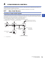
Main Shaft Module . . . . . . . . . . . . . . . . . . . . . . . . . . . . . . . . . . . . . . . . . . . . . . . . . . . . . . . . . . . . . . . . . . . . . . . 79
Overview of main shaft module . . . . . . . . . . . . . . . . . . . . . . . . . . . . . . . . . . . . . . . . . . . . . . . . . . . . . . . . . . . . . . 79
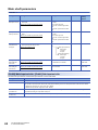
Main shaft parameters . . . . . . . . . . . . . . . . . . . . . . . . . . . . . . . . . . . . . . . . . . . . . . . . . . . . . . . . . . . . . . . . . . . . . 80
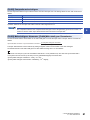
Main shaft clutch parameters . . . . . . . . . . . . . . . . . . . . . . . . . . . . . . . . . . . . . . . . . . . . . . . . . . . . . . . . . . . . . . . 82
Main shaft clutch control data . . . . . . . . . . . . . . . . . . . . . . . . . . . . . . . . . . . . . . . . . . . . . . . . . . . . . . . . . . . . . . . 86
4.2
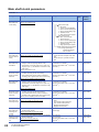
Auxiliary Shaft Module . . . . . . . . . . . . . . . . . . . . . . . . . . . . . . . . . . . . . . . . . . . . . . . . . . . . . . . . . . . . . . . . . . . 87
Overview of auxiliary shaft module . . . . . . . . . . . . . . . . . . . . . . . . . . . . . . . . . . . . . . . . . . . . . . . . . . . . . . . . . . . 87
10
Auxiliary shaft parameters . . . . . . . . . . . . . . . . . . . . . . . . . . . . . . . . . . . . . . . . . . . . . . . . . . . . . . . . . . . . . . . . . . 87
Auxiliary shaft clutch parameters. . . . . . . . . . . . . . . . . . . . . . . . . . . . . . . . . . . . . . . . . . . . . . . . . . . . . . . . . . . . . 89
Auxiliary shaft clutch control data . . . . . . . . . . . . . . . . . . . . . . . . . . . . . . . . . . . . . . . . . . . . . . . . . . . . . . . . . . . . 94
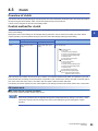
4.3
Clutch . . . . . . . . . . . . . . . . . . . . . . . . . . . . . . . . . . . . . . . . . . . . . . . . . . . . . . . . . . . . . . . . . . . . . . . . . . . . . . . . . 95
Overview of clutch . . . . . . . . . . . . . . . . . . . . . . . . . . . . . . . . . . . . . . . . . . . . . . . . . . . . . . . . . . . . . . . . . . . . . . . . 95
Control method for clutch . . . . . . . . . . . . . . . . . . . . . . . . . . . . . . . . . . . . . . . . . . . . . . . . . . . . . . . . . . . . . . . . . . 95
Smoothing method for clutch. . . . . . . . . . . . . . . . . . . . . . . . . . . . . . . . . . . . . . . . . . . . . . . . . . . . . . . . . . . . . . . 100
Use example of clutch . . . . . . . . . . . . . . . . . . . . . . . . . . . . . . . . . . . . . . . . . . . . . . . . . . . . . . . . . . . . . . . . . . . . 103
Speed Change Gear Module. . . . . . . . . . . . . . . . . . . . . . . . . . . . . . . . . . . . . . . . . . . . . . . . . . . . . . . . . . . . . . 104
Overview of speed change gear module . . . . . . . . . . . . . . . . . . . . . . . . . . . . . . . . . . . . . . . . . . . . . . . . . . . . . . 104
Speed change gear parameters . . . . . . . . . . . . . . . . . . . . . . . . . . . . . . . . . . . . . . . . . . . . . . . . . . . . . . . . . . . . 105
4.5
Output Axis Module. . . . . . . . . . . . . . . . . . . . . . . . . . . . . . . . . . . . . . . . . . . . . . . . . . . . . . . . . . . . . . . . . . . . . 106
Overview of output axis module . . . . . . . . . . . . . . . . . . . . . . . . . . . . . . . . . . . . . . . . . . . . . . . . . . . . . . . . . . . . 106
Output axis parameters . . . . . . . . . . . . . . . . . . . . . . . . . . . . . . . . . . . . . . . . . . . . . . . . . . . . . . . . . . . . . . . . . . . 108
4.6
Synchronous Control Change Function . . . . . . . . . . . . . . . . . . . . . . . . . . . . . . . . . . . . . . . . . . . . . . . . . . . . 111
Overview of synchronous control change function . . . . . . . . . . . . . . . . . . . . . . . . . . . . . . . . . . . . . . . . . . . . . . 111
CONTENTS
4.4
Synchronous control change control data . . . . . . . . . . . . . . . . . . . . . . . . . . . . . . . . . . . . . . . . . . . . . . . . . . . . . 111
4.7
Synchronous Control Monitor Data . . . . . . . . . . . . . . . . . . . . . . . . . . . . . . . . . . . . . . . . . . . . . . . . . . . . . . . . 115
4.8
Phase Compensation Function . . . . . . . . . . . . . . . . . . . . . . . . . . . . . . . . . . . . . . . . . . . . . . . . . . . . . . . . . . . 119
4.9
Output Axis Sub Functions . . . . . . . . . . . . . . . . . . . . . . . . . . . . . . . . . . . . . . . . . . . . . . . . . . . . . . . . . . . . . . 120
CHAPTER 5
SYNCHRONOUS CONTROL INITIAL POSITION
121
5.1
Synchronous Control Initial Position . . . . . . . . . . . . . . . . . . . . . . . . . . . . . . . . . . . . . . . . . . . . . . . . . . . . . . 121
5.2
Synchronous Control Initial Position Parameters . . . . . . . . . . . . . . . . . . . . . . . . . . . . . . . . . . . . . . . . . . . . 125
5.3
Cam Axis Position Restoration Method . . . . . . . . . . . . . . . . . . . . . . . . . . . . . . . . . . . . . . . . . . . . . . . . . . . . 128
Cam axis current value per cycle restoration . . . . . . . . . . . . . . . . . . . . . . . . . . . . . . . . . . . . . . . . . . . . . . . . . . 128
Cam reference position restoration . . . . . . . . . . . . . . . . . . . . . . . . . . . . . . . . . . . . . . . . . . . . . . . . . . . . . . . . . . 131
Cam axis feed current value restoration . . . . . . . . . . . . . . . . . . . . . . . . . . . . . . . . . . . . . . . . . . . . . . . . . . . . . . 132
5.4
Synchronous Control Analysis Mode . . . . . . . . . . . . . . . . . . . . . . . . . . . . . . . . . . . . . . . . . . . . . . . . . . . . . . 133
5.5
Cam Position Calculation Function . . . . . . . . . . . . . . . . . . . . . . . . . . . . . . . . . . . . . . . . . . . . . . . . . . . . . . . . 135
Cam position calculation control data . . . . . . . . . . . . . . . . . . . . . . . . . . . . . . . . . . . . . . . . . . . . . . . . . . . . . . . . 135
Cam position calculation monitor data. . . . . . . . . . . . . . . . . . . . . . . . . . . . . . . . . . . . . . . . . . . . . . . . . . . . . . . . 137
5.6
Method to Restart Synchronous Control . . . . . . . . . . . . . . . . . . . . . . . . . . . . . . . . . . . . . . . . . . . . . . . . . . . 142
APPENDICES
143
Appendix 1 List of Buffer Memory Addresses (for Synchronous Control) . . . . . . . . . . . . . . . . . . . . . . . . . . . . . 143
Appendix 2 Sample Program of Synchronous Control . . . . . . . . . . . . . . . . . . . . . . . . . . . . . . . . . . . . . . . . . . . . . 148
INDEX
152
REVISIONS . . . . . . . . . . . . . . . . . . . . . . . . . . . . . . . . . . . . . . . . . . . . . . . . . . . . . . . . . . . . . . . . . . . . . . . . . . . . .154
WARRANTY . . . . . . . . . . . . . . . . . . . . . . . . . . . . . . . . . . . . . . . . . . . . . . . . . . . . . . . . . . . . . . . . . . . . . . . . . . . .155
TRADEMARKS . . . . . . . . . . . . . . . . . . . . . . . . . . . . . . . . . . . . . . . . . . . . . . . . . . . . . . . . . . . . . . . . . . . . . . . . . .156
11
RELATED MANUALS
Manual name <manual number>
Description
MELSEC iQ-F FX5 Simple Motion Module User's Manual
(Advanced Synchronous Control)
<IB-0300255> (This manual)
Functions and programming for the synchronous control of the Simple Motion module
MELSEC iQ-F FX5 Simple Motion Module User's Manual
(Application)
<IB-0300253>
Functions, input/output signals, buffer memories, parameter settings, programming, and
troubleshooting of the Simple Motion module
MELSEC iQ-F FX5 Simple Motion Module User's Manual
(Startup)
<IB-0300251>
Specifications, procedures before operation, system configuration, wiring, and operation
examples of the Simple Motion module
This manual does not include detailed information on the followings:
• General specifications
• Available CPU modules and the number of mountable modules
• Installation
For details, refer to the following.
MELSEC iQ-F FX5U User's Manual (Hardware)
MELSEC iQ-F FX5UC User's Manual (Hardware)
e-Manual refers to the Mitsubishi FA electronic book manuals that can be browsed using a dedicated tool.
e-Manual has the following features:
• Required information can be cross-searched in multiple manuals.
• Other manuals can be accessed from the links in the manual.
• The hardware specifications of each part can be found from the product figures.
• Pages that users often browse can be bookmarked.
12
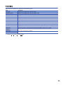
TERMS
Unless otherwise specified, this manual uses the following terms.
Term
Description
CPU module
Abbreviation for the MELSEC iQ-F series CPU module.
Simple Motion module
Abbreviation for the MELSEC iQ-F series Simple Motion module.
40SSC-S
Another term for the MELSEC iQ-F series Simple Motion module.
Servo amplifier
Abbreviation for SSCNET/H and SSCNET compatible servo amplifier.
MR-J4(W)-B
MR-J4-_B/MR-J4W_-_B Servo amplifier series
MR-J3(W)-B
MR-J3-_B/MR-J3W-_B Servo amplifier series
MR-JE-B
MR-JE-_B Servo amplifier series
Engineering tool
Generic term for GX Works3 and MR Configurator2.
GX Works3
Product name of the software package for the MELSEC programmable controllers(Version 1.005F or later).
MR Configurator2
Product name of the setup software for the servo amplifier (Version 1.34L or later).
Intelligent function module
A MELSEC iQ-F series module that has functions other than input or output, such as Simple Motion module
Manual pulse generator
Abbreviation for manual pulse generator (prepared by user).
SSCNET/H*1
High speed synchronous communication network between Simple Motion module and servo amplifier.
SSCNET*1
SSCNET(/H)
Generic term for SSCNET/H, SSCNET.
Servo network
*1
SSCNET: Servo System Controller NETwork
13
1
OUTLINE OF SYNCHRONOUS CONTROL
The outline, specifications and the operation method of synchronous control using the Simple Motion module are explained in
this chapter.
This chapter helps to understand what can be done using the positioning system and which procedure to use for a specific
purpose.
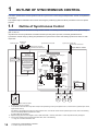
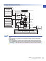
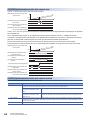
1.1
Outline of Synchronous Control
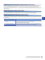
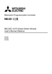
"Synchronous control" can be achieved using software instead of controlling mechanically with gear, shaft, speed change
gear or cam, etc.
"Synchronous control" synchronizes movement with the input axis (servo input axis, command generation axis or
synchronous encoder axis), by setting "the parameters for synchronous control" and starting synchronous control on each
output axis.
Positioning start
Synchronous
encoder
Synchronous control start
Synchronous control start
Synchronous control start
Manual pulse generator/
Synchronous encoder input
Synchronous
encoder axis
parameter
Synchronous encoder axis
Simple Motion module
Synchronous parameter
Main shaft
(main input axis)
Composite Main shaft gear
main shaft gear
Positioning data
Positioning control
Command generation
axis parameter
Main shaft
clutch
Command generation axis
*3
Servo input axis
parameter
Servo input axis
*1
Main shaft
(sub input axis)
Auxiliary Auxiliary
shaft
shaft
gear
clutch
Speed
change
gear *2
Speed
change
gear *2
Composite
auxiliary shaft
gear
Speed
change
gear *2
Auxiliary
shaft axis
Cam data
Cam
Output axis
Servo
amplifier
Servo
motor
Servo
amplifier
Servo
amplifier
Servo
amplifier
Servo
motor
Servo
motor
Servo
motor
It is possible to control without amplifier
by setting the virtual servo amplifier.
*1
*2
*3
14
It is possible to drive the servo input axis except for the positioning control (home position return, manual control, speed-torque control,
synchronous control).
For details on the positioning control, the home position return, the manual control and the speed-torque control, refer to the following
manual of the Simple Motion module that is used.
User's Manual (Application)
Speed change gear can be arranged on one of "Main shaft side", "Auxiliary shaft side" or "After composite auxiliary shaft gear".
For the drive method of the command generation axis, refer to the following.
Page 31 Command Generation Axis
1 OUTLINE OF SYNCHRONOUS CONTROL
1.1 Outline of Synchronous Control
List of synchronous control module
1
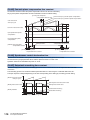
The module is used in synchronous control as follows.
Input axis module
Synchronous encoder
axis parameter
Synchronous encoder axis
Command generation
axis parameter
Synchronous parameter
Main shaft module
Main shaft Composite main Main shaft
(main input axis) shaft gear
gear
Command generation axis
Servo input axis
parameter
Servo input axis
Input axis module
Synchronous encoder
axis parameter
Synchronous encoder axis
Main shaft
(sub input axis)
Auxiliary Auxiliary
shaft
shaft
gear
clutch
Main shaft
clutch
Speed
change
gear
Speed
change
gear
Speed change
gear module
Composite
Auxiliary
auxiliary
shaft gear shaft module
Command generation
axis parameter
Command generation axis
Speed
change
gear
Servo input axis
parameter
Speed change
gear module
Servo input axis
Auxiliary
shaft axis
Auxiliary
shaft module
Speed change
Output axis
gear module
Synchronous encoder
axis parameter
Synchronous encoder axis
Cam
Cam data
Output axis
module
Command generation
axis parameter
Servo input axis
parameter
Command generation axis
Servo input axis
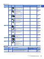
Input axis module
• Input axis module can be set to one of servo input axis, command generation axis or synchronous encoder
axis.
• Speed change gear can be arranged on one of main shaft side, auxiliary shaft side or after composite
auxiliary shaft gear.
• Set the movement amount of input axis module as large as possible to prevent the speed fluctuation of
output axis module in the synchronous control. If the movement amount of input axis module is small, the
speed fluctuation of output axis module may occur depending on the setting for synchronous parameter.
1 OUTLINE OF SYNCHRONOUS CONTROL
1.1 Outline of Synchronous Control
15
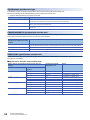
■Input axis
16
Classification
Name
Parts
Function description
Number per module
Number per axis
Input axis
module
Servo input
axis
• Used to drive the input axis with
the position of the servomotor
controlled by the Simple Motion
module.
4
Page 24
Servo Input
Axis
Command
generation
axis
• Used to drive the input axis by
generating only the positioning
command based on the
positioning data of the
command generation axis.
4
Page 31
Command
Generation
Axis
Synchronous
encoder axis
• Used to drive the input axis with
input pulse from the
synchronous encoder.
4
Page 49
Synchronous
Encoder Axis
1 OUTLINE OF SYNCHRONOUS CONTROL
1.1 Outline of Synchronous Control
Maximum number of usable
Reference
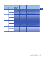
■Output axis
Classification
Name
Parts
Function description
Maximum number of usable
Number per module
Number per axis
Reference
Main shaft
main input
axis
• The input axis on the main
side of the main shaft module.
• The reference position on the
main shaft.
4
1
Page 79
Main Shaft
Module
Main shaft
sub input
axis
• The input axis on the sub side
of the main shaft module.
• It is used to input the
compensation amount for the
position of the main shaft main
input axis.
4
1
Page 79
Main Shaft
Module
Composite
main shaft
gear
• The composite movement
amount of the main shaft main
input axis and the main shaft
sub input axis are transmitted
to the main shaft gear.
4
1
Page 79
Main Shaft
Module
Main shaft
gear
• The converting movement
amount after composite main
shaft gear is transmitted by
the setting gear ratio.
4
1
Page 79
Main Shaft
Module
Main shaft
clutch
• The movement amount of the
main shaft is transmitted by
the clutch ON/OFF.
4
1
Page 79
Main Shaft
Module
Page 95
Clutch
Auxiliary
shaft axis
• The input axis of the auxiliary
shaft module.
4
1
Page 87
Auxiliary Shaft
Module
Auxiliary
shaft gear
• The converting movement
amount of the auxiliary shaft is
transmitted by the setting gear
ratio.
4
1
Page 87
Auxiliary Shaft
Module
Auxiliary
shaft clutch
• The movement amount of the
auxiliary shaft is transmitted
by the clutch ON/OFF.
4
1
Page 87
Auxiliary Shaft
Module
Page 95
Clutch
Composite
auxiliary
shaft gear
• The composite movement
amount of the main shaft and
the auxiliary shaft are
transmitted.
4
1
Page 87
Auxiliary Shaft
Module
Speed change
gear module
Speed
change
gear
• It is used to change the speed
by setting speed change ratio
during the operation.
4
1
Page 104
Speed
Change Gear
Module
Output axis
module
Output axis
• The cam conversion is
processed based on the input
movement amount and the
setting cam data.
• The feed current value is
output as the command to the
servo amplifier.
4
1
Page 106
Output Axis
Module
Main shaft
module
Auxiliary shaft
module
1
■Cam data
Classification
Name
Cam data
Cam data
Function description
Maximum number of usable
Reference
Number per module
• It controls the operation pattern of the output axis (two-way
operation and feed operation), which is corresponding to the
input movement amount of the output axis module.
Up to 256
Page 66
CAM
FUNCTION
1 OUTLINE OF SYNCHRONOUS CONTROL
1.1 Outline of Synchronous Control
17
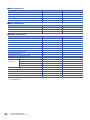
1.2
Performance Specifications
Performance specifications
Item
Input axis
Number of settable axes
Servo input axis
4 axes/module
Command generation
axis
4 axes/module
Synchronous encoder
axis
4 axes/module
Composite main shaft gear
1/output axis
Main shaft main input axis
1 axis/output axis
Main shaft sub input axis
1 axis/output axis
Main shaft gear
1/output axis
Main shaft clutch
1/output axis
Auxiliary shaft
1 axis/output axis
Auxiliary shaft gear
1/output axis
Auxiliary shaft clutch
1/output axis
Composite auxiliary shaft gear
1/output axis
Speed change gear
1/output axis
Output axis (Cam axis)
4 axes/module
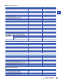
Cam specifications
Item
Specification
Memory capacity
Cam storage area
Cam open area
Number of cam registration*1
Up to 32 characters per cam data
Stroke ratio data format
Coordinate data format
*1
18
1024k bytes
Cam storage area: Up to 64
Cam open area: Up to 256
(Dependent on memory capacity, cam resolution and coordinate number)
Comment
Cam data
64k bytes
Cam resolution
256/512/1024/2048/4096/8192/16384
Stroke ratio
-214.7483648 to 214.7483647 [%]
Coordinate number
2 to 8192
Coordinate data
Input value: 0 to 2147483647
Output value: -2147483648 to 2147483647
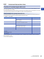
The maximum number of cam registration by the cam resolution is shown below. (In case it created by the same cam resolution.)
1 OUTLINE OF SYNCHRONOUS CONTROL
1.2 Performance Specifications
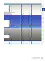
■Stroke ratio data format
Cam resolution
Maximum number of cam registration
Cam storage area
Cam open area
256
64
256
512
32
256
1024
16
256
2048
8
128
4096
4
64
8192
2
32
16384
1
16
1
■Coordinate data format
Coordinate number
Maximum number of cam registration
Cam storage area
Cam open area
128
64
256
256
32
256
512
16
256
1024
8
128
2048
4
64
4096
2
32
8192
1
16
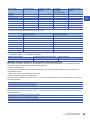
Cam operation specifications
Item
Specification
Operation method of cam data
(1) Engineering tool
Write/read/verify to cam storage area
(2) Via buffer memory (Cam data operation function)
Write/read to cam storage area and cam open area
Cam auto-generation function
Automatically generate the cam for rotary cutter.
Cam position calculation function
Calculate the cam position by the program.
Used to calculate the cam position for the synchronous control initial position before starting synchronous
control.
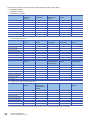
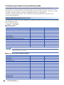
Synchronous encoder axis specifications
Item
Specification
Number of control axes
4
Synchronous encoder axis type
Incremental synchronous encoder/
Synchronous encoder via servo amplifier/
Synchronous encoder via CPU
Control unit
mm, inch, degree, pulse
(Possible to select the decimal places of position unit and speed unit)
Unit conversion
Numerator
-2147483648 to 2147483647
[Synchronous encoder axis position unit]
Denominator
1 to 2147483647
[pulse]
Length per cycle setting range
1 to 2147483647
[Synchronous encoder axis position unit]
Current value range
Current value
-2147483648 to 2147483647
[Synchronous encoder axis position unit]
Current value per cycle
0 to (Length per cycle - 1)
[Synchronous encoder axis position unit]
Control instruction
Current value change, Counter disable, Counter enable
Current value setting
address
Address setting range: -2147483648 to 2147483647
[Synchronous encoder axis position unit]
Control method
1 OUTLINE OF SYNCHRONOUS CONTROL
1.2 Performance Specifications
19
1.3
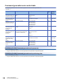
Operation Method of Synchronous Control
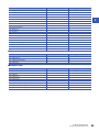
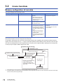
Synchronous control execution procedure
The synchronous control is executed using the following procedure.
Preparation
STEP 1
*1
Set "input axis parameters" for synchronous control.
([Pr.300] to [Pr.304], [Pr.320] to [Pr.329])
*2
Set the cam data.
*3
Set "synchronous parameters" for synchronous
control. ([Pr.400] to [Pr.468])
STEP 2
*4
Start
synchronous
control
Set the following parameters.
• Common parameters ([Pr.24], [Pr.82], [Pr.89],
[Pr.97], [Pr.150], [Pr.151])
• Positioning parameters ([Pr.1] to [Pr.4],
[Pr.7] to [Pr.22], [Pr.25] to [Pr.42], [Pr.81],
[Pr.83], [Pr.84], [Pr.90], [Pr.95],
[Pr.116] to [Pr.119])
• Expansion parameters ([Pr.91] to [Pr.94])
One of the following two methods can be used.
<Method 1>
Directly set (write) the parameters
in the Simple Motion module using
the engineering tool.
<Method 2>
Set (write) the parameters from
the CPU module to the Simple
Motion module using the program.
Create a program that executes to start / change
control / stop synchronous control.
(Set "[Cd.380]Synchronous control start", start and
stop the input axis operation and change the
reduction ratio)
STEP 3
Write the program, which is created
in STEP1 and STEP2, to the CPU module.
STEP 4
Turn ON the synchronous control start bit for
the axis that starts synchronous control.
Turn ON the target axis bit in
"[Cd.380] Synchronous control start"
and start synchronous control
by the program in STEP 2.
Verify that it's during synchronous control.
Verify that it's during synchronous control in
"[Md.26] Axis operation status".
Operate the input axis.
Operate the input axis by the program in STEP 2.
Monitor the
synchronous
control change
STEP 5
Monitor the synchronous control operation status.
Execute the control change for the speed change
ratio, cam No., etc.
Monitor using the engineering tool.
Changing the control by the program in STEP 2.
Complete
synchronous
control
STEP 6
Stop the input axis.
Stop the input axis by the program in STEP 2.
Verify the input axis is stopped and turn OFF the
synchronous control start bit for the axis that stops
synchronous control.
Turn OFF the target axis bit in
"[Cd.380] Synchronous control start"
to stop synchronous control
by the program in STEP 2.
End of control
*1
*2
*3
*4
20
Page 24 INPUT AXIS MODULE
Page 66 CAM FUNCTION
Page 79 SYNCHRONOUS CONTROL, Page 125 Synchronous Control Initial Position Parameters
Page 143 APPENDICES
1 OUTLINE OF SYNCHRONOUS CONTROL
1.3 Operation Method of Synchronous Control
Precautions
1
• Mechanical elements such as limit switches are considered as already installed.
• Parameter settings for positioning control apply for all axes with the Simple Motion module.
• Be sure to execute the home position return when the home position return request flag is ON.
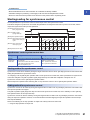
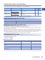
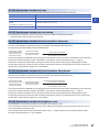
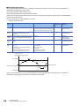
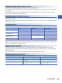
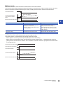
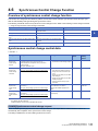
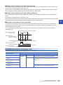
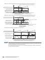
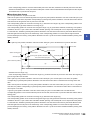
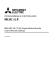
Starting/ending for synchronous control
Set the parameters for synchronous control for each output axis to start synchronous control.
The status changes to synchronous control after the parameters are analyzed at the start of synchronous control, and the
output axes synchronize with input axis operations.
[Cd.380] Synchronous control
start (Target axis bit)
[Md.141] BUSY signal
(Target axis bit)
[Md.26] Axis operation status
Standby (0)
Analyzing (5)
Synchronous control (15)
[Md.321] Synchronous encoder
axis current value per
cycle
Standby (0)
t
[Md.407] Cam axis current
value per cycle
t
[Md.20] Feed current value
t
Synchronous control system control data
Setting item
Setting details
Setting value
Default value
Buffer memory
address
[Cd.380]
Synchronous
control start
• Synchronous control begins if the target axis bit
is turned ON.
• Synchronous control ends if the bit is turned
OFF during synchronous control.
Fetch cycle: Operation cycle
■Set the target axis in 16 bits.
(bit0: axis 1 to bit3: axis 4)
OFF : Synchronous control end
ON : Synchronous control start
0
36320
Starting method for synchronous control
Synchronous control can be started by turning the target axis bit from OFF to ON in "[Cd.380] Synchronous control start" after
setting the parameters for synchronous control.
"5: Analyzing" is set in "[Md.26] Axis operation status" at the synchronous control start, and the parameters for synchronous
control are analyzed. The "[Md.141] BUSY signal (Target axis bit)" turns ON after completion of analysis, and "15:
Synchronous control" is set in "[Md.26] Axis operation status".
Start the input axis operation after confirming that "15: Synchronous control" is set in "[Md.26] Axis operation status".
Ending method for synchronous control
Synchronous control can be ended by turning the target axis bit from ON to OFF in "[Cd.380] Synchronous control start" after
the input axis operation is stopped.
The "[Md.141] BUSY signal (Target axis bit)" turns OFF at the synchronous control end, and "0: Standby" is set in "[Md.26]
Axis operation status" at the output axis stop.
Synchronous control can also be ended by turning the target axis bit from ON to OFF in "[Cd.380] Synchronous control start"
during the input axis operation. However, it is recommended to end after stopping the input axis operation since the output
axis stops immediately.
Refer to the following for the stop operation of output axis at the synchronous control end.
Page 23 Stop operation of output axis
1 OUTLINE OF SYNCHRONOUS CONTROL
1.3 Operation Method of Synchronous Control
21
Starting history
The starting history is updated when starting synchronous control. "9020: Synchronous control operation" is stored in "[Md.4]
Start No.".
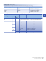
Status when starting synchronous control
The following bits in "[Md.31] Status" are turned OFF when starting synchronous control in the same way as for the positioning
control start.
Bit
Details
b0
In speed control flag
b1
Speed-position switching latch flag
b2
Command in-position flag
b4
Home position return complete flag
b5
Position-speed switching latch flag
b10
Speed change 0 flag
• If bit for multiple axes are turned ON simultaneously in "[Cd.380] Synchronous control start", control is not
started simultaneously since the analysis is processed for each axis in numerical order. When the multiple
axes must be started simultaneously, start the input axis operation after confirming that all axes are
configured for the synchronous control.
• If the input axis operates during the analysis at the synchronous control start, the movement amount of the
input axis is reflected immediately after the synchronous control start. The output axis might suddenly
accelerate depending on the movement amount of the input axis. Start the input axis operation after
confirming that are configured for synchronous control.
• The analysis process for synchronous control start might take time depending on the parameter setting for
synchronous control. (Up to about 14 ms: When "0: Cam axis current value per cycle restoration" is set in
"[Pr.462] Cam axis position restoration object" and the cam (cam resolution: 16384) is searched) Set "1:
Cam reference position restoration" or "2: Cam axis feed current value restoration" in "[Pr.462] Cam axis
position restoration object" to start synchronous control at high speed.
• When the synchronous control parameter is set to the value outside the setting range, the synchronous
control does not start, and the input axis error No. is stored in the monitor data.
22
1 OUTLINE OF SYNCHRONOUS CONTROL
1.3 Operation Method of Synchronous Control
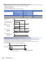
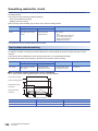
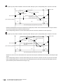
Stop operation of output axis
1
If the following causes occur in stopping the output axis during synchronous control, synchronous control is completed after
stops processing for the output axis ("[Md.141] BUSY signal" is OFF, "[Md.26] Axis operation status" is standby).
Synchronous alignment must be executed for the output axis to restart the synchronous control. (Page 106 Output Axis
Module)
Stop cause
Stop process
The target axis bit of "[Cd.380] Synchronous control start" is turned from ON to OFF.
Immediate stop
Software stroke limit error occurrence
Emergency stop
Forced stop
Stop group1 to 3*1 (Stop with hardware stroke limit or stop command)
*1
Deceleration stop
Refer to "User's Manual (Application)" of the Simple Motion module that is used.
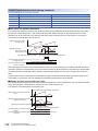
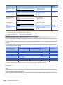
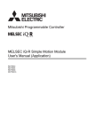
Immediate stop
The operation stops without decelerate. The Simple Motion module immediately stops the command, but the operation will
coast for the droop pulses accumulated in the deviation counter of the servo amplifier.
[Md.407] Cam axis current value
per cycle
t
[Md.20] Feed current value
(Cam operation)
t
t
[Md.22] Feedrate
Immediate stop
[Cd.380] Synchronous control start
(Target axis bit)
[Md.141] BUSY signal
(Target axis bit)
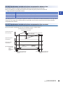
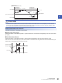
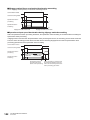
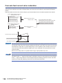
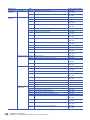
Deceleration stop
The output axis stops with deceleration according to the setting in "[Pr.37] Stop group 1 sudden stop selection" to "[Pr.39] Stop
group 3 sudden stop selection". The deceleration time is set in "[Pr.446] Synchronous control deceleration time" for
deceleration stop, and in "[Pr.36] Sudden stop deceleration time" for sudden stop. The slope of deceleration is as follows.
Slope of deceleration = "[Pr.8] Sped limit value" /
Deceleration time
(Sudden stop deceleration time)
The cam axis current value per cycle is not updated, and only the feed current value is updated, since the deceleration stop
begins. Therefore, the path of the feed current value is drawn regardless the cam operation with deceleration stop.
The input axis must be stopped when the output axis is stop synchronizing with the input axis.
[Md.407] Cam axis current value
per cycle
[Md.20] Feed current value
(Cam operation)
[Md.22] Feedrate
[Cd.380] Synchronous control start
(Target axis bit)
t
t
t
Deceleration stop
Axis stop signal
[Md.141] BUSY signal
(Target axis bit)
1 OUTLINE OF SYNCHRONOUS CONTROL
1.3 Operation Method of Synchronous Control
23
2
INPUT AXIS MODULE
The settings for the parameter and monitor data for the input axis module that used with synchronous control are explained in
this chapter.
Refer to the following manual of the Simple Motion module that is used for details on the connection and control for the servo
amplifier and the synchronous encoder that used for input axis module.
User's Manual (Application)
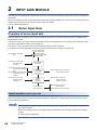
2.1
Servo Input Axis
Overview of servo input axis
The servo input axis is used to drive the input axis based on the position of the servomotor that is being controlled by the
Simple Motion module.
The status of a servo input axis can also be monitored even before the synchronous control start since the setting of a servo
input axis is valid after the system's power supply ON.
The status of a servo input axis can be monitored after the system’s power supply ON.
The following shows the relationship between the position of the servomotor and the servo input axis.
[Pr.300] Servo input axis
type
[Pr.301] Servo input axis
smoothing time
constant
[Pr.302] Servo input axis phase
compensation advance
time
[Pr.303] Servo input axis phase
compensation time
constant
[Pr.304] Servo input axis
rotation direction
restriction
Servo motor position
Feed current value
Real current value
Servo command value
Feedback value
Input smoothing
processing
Phase
compensation
processing
Rotation
direction
restriction
Current value of
servo input axis
[Md.302] Servo input axis phase
compensation amount
[Md.303] Servo input axis
rotation direction
restriction amount
[Md.300] Servo input axis
current value
[Md.301] Servo input axis speed
Control method for servo input axis
All controls (including synchronous control) can be executed for a servo input axis.
Refer to the following manual of the Simple Motion module that is used for the controls other than the synchronous control.
User's Manual (Application)
If the virtual servo amplifier function is set in the servo input axis, synchronous control can be executed by the
input value as virtual.
Refer to the following manual of the Simple Motion module that is used for details on virtual servo amplifier
function.
User's Manual (Application)
24
2 INPUT AXIS MODULE
2.1 Servo Input Axis
If "1: Feed current value" or "2: Real current value" is set in "[Pr.300] Servo input axis type", set "1: Update
feed current value" in "[Pr.21] Feed current value during speed control" to start the speed position change
control. If "0: Do not update feed current value" or "2: Clear feed current value to zero" is set in [Pr.21], the
error "Speed-position switching control start in servo input axis not possible" (error code: 1BA7H) will occur
2
and the control will not start.
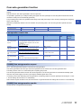
Units for the servo input axis
The position units and speed units for the servo input axis are shown below for the setting "[Pr.300] Servo input axis type" and
"[Pr.1] Unit setting".
■Servo input axis position units
Setting value of "[Pr.300]
Servo input axis type"
Setting value of "[Pr.1] Unit
setting"
Servo input axis position
unit
Range
1: Feed current value
2: Real current value
0: mm
10-4 mm
(10-1 m)
-214748.3648 to 214748.3647 [mm]
(-214748364.8 to 214748364.7 [m])
1: inch
10-5 inch
-21474.83648 to 21474.83647 [inch]
3: Servo command value
4: Feedback value
-5
2: degree
10
3: pulse
pulse
-2147483648 to 2147483647 [pulse]
pulse
-2147483648 to 2147483647 [pulse]
degree
-21474.83648 to 21474.83647 [degree]
■Servo input axis speed units
Setting value of "[Pr.300]
Servo input axis type"
Setting value of "[Pr.1] Unit
setting"
Servo input axis speed unit
Range
1: Feed current value
2: Real current value
0: mm
10-2 mm/min
-21474836.48 to 21474836.47 [mm/min]
3: Servo command value
4: Feedback value
*1
10-3
1: inch
2: degree
10-3 degree/min*1
-2147483.648 to 2147483.647 [degree/min]*1
3: pulse
pulse/s
-2147483648 to 2147483647 [pulse/s]
pulse/s
-2147483648 to 2147483647 [pulse/s]
inch/min
-2147483.648 to 2147483.647 [inch/min]
When "[Pr.83] Speed control 10 x multiplier setting for degree axis" is valid, this will be the speed unit " 10-2 degree/min"
(Range: - 21474836.48 to 21474836.47 [degree/min]).
• When "1: Feed current value" or "3: Servo command value" is set in "[Pr.300] Servo input axis type", and the
servo input axis becomes servo OFF by the servo alarm or forced stop, the amount of value change may be
large. This can be prevented by setting "2: Real current value" or "4: Feedback value" in "[Pr.300] Servo
input axis type".
• When a home position return for the axis where "1: Feed current value" or "2: Real current value" is set in
"[Pr.300] Servo input axis type" is performed, if the servo input axis operation during home position return is
used as the input value, the input is stopped in the midway of home position return. When the servo input
axis operation during home position return is used as the input value, set "3: Servo command value" or "4:
Feedback value" in "[Pr.300] Servo input axis type".
2 INPUT AXIS MODULE
2.1 Servo Input Axis
25
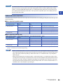
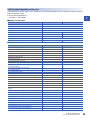
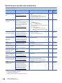
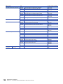
Servo input axis parameters
n: Axis No. - 1
Setting item
Setting details
Setting value
Default value
Buffer memory
address
[Pr.300]
Servo input axis type
• Set the current value type to be
generated of the input value for the
servo input axis.
Fetch cycle: At power supply ON
■Set in decimal.
0: Invalid
1: Feed current value
2: Real current value
3: Servo command value
4: Feedback value
0
32800+10n
[Pr.301]
Servo input axis smoothing time
constant
• Set to smooth the input value.
Fetch cycle: At power supply ON
■Set in decimal.
0 to 5000 [ms]
0
32801+10n
[Pr.302]
Servo input axis phase compensation
advance time
• Set the time to advance or delay
the phase.
Fetch cycle: Operation cycle
■Set in decimal.
-2147483648 to 2147483647 [s]
0
32802+10n
32803+10n
[Pr.303]
Servo input axis phase compensation
time constant
• Set the time constant to affect the
phase compensation.
Fetch cycle: At power supply ON
■Set in decimal.
0 to 65535 [ms]*1
10
32804+10n
[Pr.304]
Servo input axis rotation direction
restriction
• Set this parameter to restrict the
input movement amount to one
direction.
Fetch cycle: At power supply ON
■Set in decimal.
0: Without rotation direction
restriction
1: Enable only for current value
increase direction
2: Enable only for current value
decrease direction
0
32805+10n
*1
Set the value as follows in a program.
0 to 32767: Set as a decimal.
32768 to 65535: Convert into a hexadecimal and set.
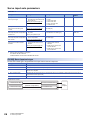
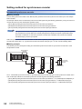
[Pr.300] Servo input axis type
Set the current value type to be generated of the input value for the servo input axis.
Setting value
Details
0: Invalid
Servo input axis is invalid.
1: Feed current value
Generate the input value based on "[Md.20] Feed current value".
2: Real current value
Generate the input value based on the real current value, which is converted into units of the encoder feedback pulses
from the servo amplifier.
3: Servo command value
Generate the input value based on the command pulse for the servo amplifier (a value that the feed current value is
converted into encoder pulse units).
4: Feedback value
Generate the input value based on the encoder feedback pulse from the servo amplifier.
Simple Motion module
1: Feed current value
2: Real current value
26
2 INPUT AXIS MODULE
2.1 Servo Input Axis
Unit → Pulse conversion
(Backlash compensation)
Pulse → Unit conversion
3: Servo command value
Servo
amplifier
4: Feedback value
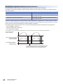
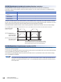
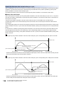
[Pr.301] Servo input axis smoothing time constant
Set the averaging time to execute a smoothing process for the input movement amount from the servo input axis.
The smoothing process can moderate speed fluctuation, when the "Real current value" or "Feedback value" is used as input
values. The input response is delayed depending on the time corresponding to the setting by smoothing process setting.
2
Input value speed
before smoothing
t
Averaging by
smoothing time constant
Input value speed
after smoothing
t
[Pr.301] Servo input axis smoothing
time constant
[Pr.301] Servo input axis smoothing
time constant
[Pr.302] Servo input axis phase compensation advance time
Set the time to advance or delay the phase (input response) of the servo input axis.
Refer to the following for the delay time inherent to the system using the servo input axis.
Page 119 Phase Compensation Function
Setting value
Details
1 to 2147483647 [s]
Advance the phase (input response) according to the setting time.
0 [s]
Do not execute phase compensation.
-2147483648 to -1 [s]
Delay the phase (input response) according to the setting time.
If the setting time is too long, the system experiences overshoot or undershoot at acceleration/deceleration of the input speed.
In this case, set longer time to affect the phase compensation amount in "[Pr.303] Servo input axis phase compensation time
constant".
[Pr.303] Servo input axis phase compensation time constant
Set the time constant to affect the phase compensation amount for the first order delay.
63 [%] of the phase compensation amount are reflected in the time constant setting.
[Pr.302] Servo input axis phase
compensation advance time
Servo input axis
current value
Current value before phase compensation
Current value after
phase compensation
t
Speed before phase
compensation
t
Speed after phase
compensation
[Md.302] Servo input
axis phase
compensation
amount
[Md.302] Servo input axis
Speed before
×
phase compensation
phase
amount
compensation
63%
[Pr.303] Servo input axis phase
compensation time constant
t
63%
t
[Pr.303] Servo input axis phase
compensation time constant
2 INPUT AXIS MODULE
2.1 Servo Input Axis
27
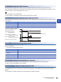
[Pr.304] Servo input axis rotation direction restriction
Set this parameter to restrict the input movement amount for the servo input axis to one direction.
This helps to avoid reverse operation caused by machine vibration, etc. when "Real current value" or "Feedback value" is
used as input values.
Setting value
Details
0: Without rotation direction restriction
Rotation direction restriction is not executed.
1: Enable only for current value increase direction
Enable only the input movement amount in the increasing direction of the
servo input axis current value.
2: Enable only for current value decrease direction
Enable only the input movement amount in the decreasing direction of the
servo input axis current value.
The input movement amount in the reverse direction of the enabled direction accumulates as a rotation direction restricted
amount, and will be reflected when the input movement amount moves in the enabled direction again. Therefore, the current
value of servo input does not deviate when the reverse operation is repeated.
The rotation direction restricted amount is set to 0 when the following operations are executed for the servo input axis.
• A servo amplifier is connected
• The home position return is executed
• The current value is changed
For "1: Enable only for current value increase direction" is set in "[Pr.304] Servo input axis rotation direction restriction".
Speed before rotation
direction restriction
t
[Md.301] Servo input axis speed
(Speed after rotation
direction restriction)
t
[Md.303] Servo input axis
rotation direction
restriction amount
t
The input movement amount is accumulated as a rotation
direction restricted amount, and will be reflected when
the input movement amount in the enabled direction.
28
2 INPUT AXIS MODULE
2.1 Servo Input Axis
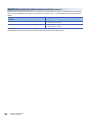
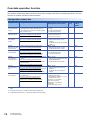
Servo input axis monitor data
n: Axis No. - 1
Monitor item
Storage details
Monitor value
Buffer memory
address
[Md.300]
Servo input axis current value
• The current value for the servo input axis
is stored.
Refresh cycle: Operation cycle
■Monitoring is carried out in decimal.
-2147483648 to 2147483647
[Servo input axis position units*1]
33120+10n
33121+10n
[Md.301]
Servo input axis speed
• The speed for the servo input axis is
stored.
Refresh cycle: Operation cycle
■Monitoring is carried out in decimal.
-2147483648 to 2147483647
[Servo input axis speed units*2]
33122+10n
33123+10n
[Md.302]
Servo input axis phase compensation
amount
• The current phase compensation amount
is stored.
Refresh cycle: Operation cycle
■Monitoring is carried out in decimal.
-2147483648 to 2147483647
[Servo input axis position units*1]
33124+10n
33125+10n
[Md.303]
Servo input axis rotation direction restriction
amount
• While the rotation direction is restricted,
the accumulation for the input movement
amount in the opposite direction of the
enabled direction is stored.
Refresh cycle: Operation cycle
■Monitoring is carried out in decimal.
-2147483648 to 2147483647
[Servo input axis position units*1]
33126+10n
33127+10n
*1
*2
2
Servo input axis position units (Page 25 Servo input axis position units)
Servo input axis speed units (Page 25 Servo input axis speed units)
[Md.300] Servo input axis current value
The current value for the servo input axis is stored in servo input axis position units (Page 25 Servo input axis position
units) as follows.
The current value for the servo input axis is the value after processing the smoothing, the phase compensation and the
rotation direction restriction.
Setting value of "[Pr.300] Servo input axis type"
Storage details
1: Feed current value
2: Real current value
• The accumulative current value started with "[Md.20] Feed current value"/"[Md.101]
Real current value" for the connection to the servo amplifier is stored. It is also stored in
the range from -21474.83648 to 21474.83647 [degree] for degree units.
• When the "[Md.20] Feed current value"/"[Md.101] Real current value" is changed by the
home position return or the current value change, the value is changed to the new
current value.
3: Servo command value
4: Feedback value
• When of the absolute position detection system setting is invalid, the accumulative
current value that starts from 0 for the connected servo amplifier is stored.
• When of the absolute position detection system setting is valid, the accumulative
current value that starts from the absolute position command/encoder feedback pulse
for the connected servo amplifier is stored.
• The servo input axis current value will not change, even if the home position return or
the current value is changed.
[Md.301] Servo input axis speed
The speed for the servo input axis is stored in servo input axis speed units (Page 25 Servo input axis speed units).
The speed for the servo input axis is the value after processing smoothing, phase compensation, and rotation direction
restriction.
[Md.302] Servo input axis phase compensation amount
The phase compensation amount for a servo input axis is stored in servo input axis position units (Page 25 Servo input
axis position units).
The phase compensation amount for a servo input axis is the value after processing smoothing and phase compensation.
2 INPUT AXIS MODULE
2.1 Servo Input Axis
29
[Md.303] Servo input axis rotation direction restriction amount
While the rotation direction is restricted for a servo input axis, the accumulation for input movement amount in the opposite
direction of the enabled direction is stored in servo input axis position units (Page 25 Servo input axis position units) as
follows.
Setting value of "[Pr.304] Servo input axis rotation direction
restriction"
Storage details
1: Enable only for current value increase direction
A negative accumulation is stored during rotation direction restriction.
0 is stored if there is no restriction.
2: Enable only for current value decrease direction
A positive accumulation is stored during rotation direction restriction.
0 is stored if there is no restriction.
Rotation direction restriction is processed after phase compensation processing. Therefore, if undershoot occurs from phase
compensation during deceleration stop, the rotation direction restriction amount might remain.
30
2 INPUT AXIS MODULE
2.1 Servo Input Axis
2.2
Command Generation Axis
Overview of command generation axis
The command generation axis is an axis that executes command generation only. It can be controlled individually from the
2
axis connected with a servo amplifier.
The command generation axis is used to drive the input axis based on the positioning data or the JOG operation. The axis set
in "[Pr.100] Servo series" is defined as "servo amplifier axis" against "command generation axis".
Control method for the command generation axis
The command generation axis operates following to the positioning data and control data of the command generation axis.
The controls that can be used for the command generation axis are shown below.
: Available, : Not available
Control mode
Control
Availability
Linear control
ABS linear 1, INC linear 1
ABS linear 2, INC linear 2
ABS linear 3, INC linear 3
ABS linear 4, INC linear 4
ABS circular sub, ABS circular right, ABS circular left
INC circular sub, INC circular right, INC circular left
Fixed-feed
Fixed-feed 1, Fixed-feed 2, Fixed-feed 3, Fixed-feed 4
Speed control
Forward run speed 1, Reverse run speed 1
Forward run speed 2, Reverse run speed 2
Forward run speed 3, Reverse run speed 3
Forward run speed 4, Reverse run speed 4
Speed-position control
Forward run speed/position, Reverse run speed/position
Position-speed control
Forward run position/speed, Reverse run position/speed
Circular interpolation control
Current value change
Simultaneous start
JOG operation
Manual pulse generator operation
Home position return
The control details are common with "major positioning controls". For details, refer to the following manual of the Simple
Motion module that is used.
User's Manual (Application)
2 INPUT AXIS MODULE
2.2 Command Generation Axis
31
The sub functions that can be used for the command generation axis are shown below.
: Combination possible
: Combination restricted
: Combination not possible
Control mode
Home position
return retry
function
Home position
shift function
Backlash
compensation
function
Electronic gear
function
Near pass function
ABS linear 1
*1
INC linear 1
*1
Forward run speed 1
*1
Reverse run speed 1
*1
Forward run speed/position
*1
Reverse run speed/position
*1
Current value change
*1
JOG operation
*1
Control mode
Speed limit
function
Torque limit
function
Software stroke
limit function
Hardware stroke
limit function
Forced stop
function
ABS linear 1
INC linear 1
Forward run speed 1
Reverse run speed 1
Forward run speed/position
Reverse run speed/position
Current value change
JOG operation
Control mode
Speed change
function
Override function
Acceleration/
deceleration time
change function
Torque change
function
Target position
change function
ABS linear 1
*2
INC linear 1
*2
Forward run speed 1
Reverse run speed 1
Forward run speed/position
Reverse run speed/position
Current value change
JOG operation
*2
Invalid during the continuous path control mode.
Control mode
Pre-reading start
function
Stop command
processing for
deceleration stop
function
Step function
Skip function
M code output
function
ABS linear 1
INC linear 1
Forward run speed 1
Reverse run speed 1
Forward run speed/position
Reverse run speed/position
Current value change
*3
JOG operation
*3
32
The near pass function is validated only when the machine of the standard specification carries out the position control with the
continuous path control mode.
Execute the current value change using the positioning data. It is not output using the positioning start No.9003.
2 INPUT AXIS MODULE
2.2 Command Generation Axis
Control mode
Teaching function
Command in-position
function
Acceleration/
deceleration
processing function
Deceleration start flag
function
ABS linear 1
INC linear 1
Forward run speed 1
Reverse run speed 1
Forward run speed/position
*4
Reverse run speed/position
*4
Current value change
JOG operation
*4
2
Valid only when the deceleration start during positioning control.
Control mode
Speed control 10 times multiplier setting for
degree axis function
Operation setting for incompletion of home
position return function
ABS linear 1
INC linear 1
Forward run speed 1
Reverse run speed 1
Forward run speed/position
Reverse run speed/position
Current value change
JOG operation
The following shows the support status of sub functions excluding above.
: Combination possible, : Combination not possible
Absolute position system
Continuous operation interrupt function
Follow up function
■Change command generation axis parameters and positioning data
The command generation axis does not store parameters or positioning data in the buffer memory. Therefore, rewrite the
parameters and the positioning data using the following methods.
• When using GX Works3
Set the command generation axis parameters and positioning data using GX Works3. After that, execute "writing to the
Simple Motion module".
• When using command generation axis control data
[Change command generation axis parameters]
Use the following control data. For details, refer to Page 46 Write/read method for command generation axis parameter
and positioning data.
[Cd.300] Command generation axis parameter No. designation
[Cd.301] Command generation axis parameter setting value
[Cd.302] Command generation axis parameter control request
[Change command generation axis positioning data]
Use the following control data. For details, refer to Page 46 Write/read method for command generation axis parameter
and positioning data.
[Cd.303] Command generation axis positioning data No. designation
[Cd.304] Command generation axis positioning data designation
[Cd.305] Command generation axis positioning data setting value
[Cd.306] Command generation axis positioning data control request
2 INPUT AXIS MODULE
2.2 Command Generation Axis
33
■Setting for command generation axis
Set "1: Valid" in "[Pr.340] Command generation axis valid setting" using the methods above. The command generation axis
setting is fetched at the power ON. Therefore, to disconnect the command generation axis, turn ON the Simple Motion module
power supply again after setting "Other than 1: Invalid" in "[Pr.340] Command generation axis valid setting".
■Start request
Specify the positioning data number in "[Cd.3] Positioning start No." and set "1: ON" in "[Cd.184] Positioning start signal". The
start complete signal ([Md.31] Status: b14) and "[Md.141] BUSY signal" turn ON, and the positioning operation starts.
■Troubleshooting
Output the axis error and warning which are same as the servo amplifier axis to "[Md.23] Axis error No." and "[Md.24] Axis
warning No." of the command generation axis.
Units for the command generation axis
The position units and speed units for the command generation axis are shown below based on the setting "[Pr.1] Unit
setting".
■Command generation axis position units
Setting value of "[Pr.1] Unit setting"
Command generation axis position unit
Range
0: mm
10-1 m
-214748364.8 to 214748364.7 [m]
10-5
1: inch
2: degree
10-5 degree
0.00000 to 359.99999 [degree]
3: pulse
pulse
-2147483648 to 2147483647 [pulse]
inch
-21474.83648 to 21474.83647 [inch]
■Command generation axis speed units
Setting value of "[Pr.1] Unit setting"
Command generation axis speed unit
Range
0: mm
10-2 mm/min
-21474836.48 to 21474836.47 [mm/min]
1: inch
10-3 inch/min
-2147483.648 to 2147483.647 [inch/min]
2: degree
10-3 degree/min*1
-2147483.648 to 2147483.647 [degree/min]*1
3: pulse
pulse/s
-2147483648 to 2147483647 [pulse/s]
*1
When "[Pr.83] Speed control 10 x multiplier setting for degree axis" is valid, this will be the speed unit " 10-2 degree/min"
(Range: - 21474836.48 to 21474836.47 [degree/min]).
Operation at forced stop
When the command generation axis starts while "0: Valid" is set to "[Pr.82] Forced stop valid/invalid selection", the error "Start
not possible" (error code: 1928H) occurs and the command generation axis does not start. When the forced stop input signal
turns OFF during operation, the axis stops suddenly according to the setting of "[Pr.36] Sudden stop deceleration time" and
"1: Stopped" is set in "[Md.26] Axis operation status".
The forced stop setting can be changed by "[Pr.82] Forced stop valid/invalid selection". "[Pr.82] Forced stop valid/invalid
selection" and "forced stop input signal" are common with the servo amplifier axis.
34
2 INPUT AXIS MODULE
2.2 Command Generation Axis
Command generation axis parameters
All command generation axis parameters are prepared for each command generation axis. However, change the parameters
using GX Works3 or control data because the parameters are not in the buffer memory.
Setting item
Setting details
Setting value
Default
value
Buffer
memory
address
[Pr.340]
Command generation axis
valid setting
• Set valid/invalid of the command
generation axis to be used.
Fetch cycle: At power supply ON
■Set in decimal.
Other than 1: Invalid
1: Valid
0
[Pr.346]
Command generation axis
length per cycle
• Set the length per cycle of the
command generation axis.
Fetch cycle: At power supply ON
■Set in decimal.
0: Invalid
1 to 2147483647
[Command generation axis position units*1]
0
*1
2
Command generation axis position units (Page 34 Command generation axis position units)
[Pr.340] Command generation axis valid setting
Set valid/invalid of the command generation axis.
Setting value
Details
Other than 1: Invalid
Command generation axis is invalid.
1: Valid
Command generation axis is valid.
[Pr.346] Command generation axis length per cycle
Set the length per cycle for the command generation axis current value per cycle.
The current value of command generation axis is stored in "[Md.347] Command generation axis current value per cycle" at
ring counter based on the setting value.
The unit settings are in command generation axis position units (Page 34 Command generation axis position units).Set a
value within the range from 1 to 2147483647. If a value out of the range is input, the axis error "Outside command generation
axis length per cycle setting error" (error code: 1BADH) occurs and the axis operates as that the length per cycle is 0.
If "0" is set, "[Md.347] Command generation axis current value per cycle" is not updated.
List of parameters that can be used
Each parameter specification is common with the servo amplifier axis. For specification details, refer to the following manual
of the Simple Motion module that is used.
User's Manual (Application)
: Available, : Not available
■Common parameters
Name
Servo amplifier axis
Command generation axis
[Pr.24] Manual pulse generator/Incremental synchronous encoder input
selection
[Pr.82] Forced stop valid/invalid selection
: Servo amplifier axis and command generation axis in common
[Pr.89] Manual pulse generator/Incremental synchronous encoder input
type selection
[Pr.97] SSCNET setting
[Pr.150] Input terminal logic selection
[Pr.151] Manual pulse generator/ Incremental synchronous encoder
input logic selection
2 INPUT AXIS MODULE
2.2 Command Generation Axis
35
■Basic parameters1
Name
Servo amplifier axis
Command generation axis
[Pr.1] Unit setting
: Fetch cycle is at power supply ON.
[Pr.2] Number of pulses per rotation (AP)
[Pr.3] Movement amount per rotation (AL)
[Pr.4] Unit magnification (AM)
[Pr.7] Bias speed at start
Name
Servo amplifier axis
Command generation axis
[Pr.8] Speed limit value
[Pr.9] Acceleration time 0
[Pr.10] Deceleration time 0
Name
Servo amplifier axis
Command generation axis
[Pr.11] Backlash compensation amount
[Pr.12] Software stroke limit upper limit value
: Initial value 0 *1
[Pr.13] Software stroke limit lower limit value
: Initial value 0 *1
[Pr.14] Software stroke limit selection
[Pr.15] Software stroke limit valid/invalid setting
: Initial value 1 *1
[Pr.16] Command in-position width
[Pr.17] Torque limit setting value
[Pr.18] M code ON signal output timing
[Pr.19] Speed switching mode
[Pr.20] Interpolation speed designation method
[Pr.21] Current feed value during speed control
*2
[Pr.22] Input signal
logic selection
b0: Lower limit
b1: Upper limit
b3: Stop signal
b6: Near-point dog signal
[Pr.81] Speed-position function selection
[Pr.116] FLS signal selection
[Pr.117] RLS signal selection
[Pr.118] DOG signal selection
[Pr.119] STOP signal selection
■Basic parameters2
■Detailed parameters1
*1
*2
36
Different from the servo amplifier axis, the initial value of software stroke limit is invalid.
It operates fixed to 1.
2 INPUT AXIS MODULE
2.2 Command Generation Axis
■Detailed parameters2
Name
Servo amplifier axis
Command generation axis
[Pr.25] Acceleration time 1
[Pr.26] Acceleration time 2
[Pr.27] Acceleration time 3
[Pr.28] Deceleration time 1
[Pr.29] Deceleration time 2
[Pr.30] Deceleration time 3
[Pr.31] JOG speed limit value
[Pr.32] JOG operation acceleration time selection
[Pr.33] JOG operation deceleration time selection
[Pr.34] Acceleration/deceleration process selection
[Pr.35] S-curve ratio
[Pr.36] Sudden stop deceleration time
[Pr.37] Stop group 1 sudden stop selection
[Pr.38] Stop group 2 sudden stop selection
[Pr.39] Stop group 3 sudden stop selection
[Pr.40] Positioning complete signal output time
[Pr.41] Allowable circular interpolation error width
[Pr.42] External command function selection
[Pr.83] Speed control 10 times multiplier setting for degree axis
[Pr.84] Restart allowable range when servo OFF to ON
b4 to b7: Torque initial value selection
b8 to b11: Speed initial value selection
b12 to b15: Condition selection at mode
switching
Name
Servo amplifier axis
Command generation axis
[Pr.43] Home position return method
[Pr.44] Home position return direction
[Pr.45] Home position address
[Pr.46] Home position return speed
[Pr.47] Creep speed
[Pr.48] Home position return retry
Name
Servo amplifier axis
Command generation axis
[Pr.50] Setting for the movement amount after near-point dog ON
[Pr.51] Home position return acceleration time selection
[Pr.52] Home position return deceleration time selection
[Pr.53] Home position shift amount
[Pr.54] Home position return torque limit value
[Pr.55] Operation setting for incompletion of home position return
[Pr.56] Speed designation during home position shift
[Pr.57] Dwell time during home position return retry
Name
Servo amplifier axis
Command generation axis
[Pr.91] Optional data monitor: Data type setting 1
[Pr.92] Optional data monitor: Data type setting 2
[Pr.93] Optional data monitor: Data type setting 3
[Pr.94] Optional data monitor: Data type setting 4
[Pr.90] Operation
setting for speedtorque control mode
[Pr.95] External command signal selection
2
■Home position return basic parameters
■Home position return detailed parameters
■Expansion parameters
2 INPUT AXIS MODULE
2.2 Command Generation Axis
37
Command generation axis control data
All command generation axis control data is prepared for each command generation axis.
n: Axis No. - 1
Setting item
Setting details
Setting value
Default
value
Buffer
memory
address
[Cd.300]
Command generation axis
parameter No. designation
Specify the parameter number to be
written.
■Set in decimal.
Parameter number
1 to 400
0
61970+128n
[Cd.301]
Command generation axis
parameter setting value
Specify the setting value to be written.
■Set in decimal.
-2147483648 to 2147483647
0
61972+128n
61973+128n
[Cd.302]
Command generation axis
parameter control request
Set the writing command.
■Set in hexadecimal.
0000H: Not request
0001H: Write request
0002H: Read request
FFFFH: Write error
0000H
61971+128n
[Cd.303]
Command generation axis
positioning data No.
designation
Specify the positioning data number to
be written.
■Set in decimal.
Data number
1 to 100
0
61974+128n
[Cd.304]
Command generation axis
positioning data
designation
Specify [Da._] of the positioning data
number to be written (positioning data,
block start data, condition data).
■Set in decimal.
Data number specification
[Da.1]: 1
[Da.2]: 2
[Da.26]: 26
0
61975+128n
[Cd.305]
Command generation axis
positioning data setting
value
Specify the setting value to be written.
■Set in decimal.
-2147483648 to 2147483647
0
61976+128n
61977+128n
[Cd.306]
Command generation axis
positioning data control
request
Set the writing command.
■Set in hexadecimal.
0000H: Not request
0001H: Write request
0002H: Read request
FFFFH: Write Error
0000H
61978+128n
[Cd.300] to [Cd.302] Command generation axis parameter
Refer to the following for details.
Page 46 Write/read method for command generation axis parameter and positioning data
[Cd.303] to [Cd.306] Command generation axis positioning data
Refer to the following for details.
Page 46 Write/read method for command generation axis parameter and positioning data
38
2 INPUT AXIS MODULE
2.2 Command Generation Axis
List of control data that can be used
The specification is common with the servo amplifier axis. For specification details, refer to the following manual of the Simple
Motion module that is used.
User's Manual (Application)
2
: Available, : Not available
■System control data
Name
Servo amplifier axis
[Cd.1] Flash ROM write request
: Servo amplifier axis and command generation axis in common
Command generation axis
[Cd.2] Parameter initialization request
: Servo amplifier axis and command generation axis in common
[Cd.41] Deceleration start flag valid
: Servo amplifier axis and command generation axis in common
[Cd.42] Stop command processing for deceleration stop selection
: Servo amplifier axis and command generation axis in common
[Cd.44] External input signal operation device (Axis 1 to 4)
[Cd.102] SSCNET control command
[Cd.137] Amplifier-less operation mode switching request
[Cd.190] PLC READY signal
: Servo amplifier axis and command generation axis in common
[Cd.191] All axis servo ON signal
Name
Servo amplifier axis
Command generation axis
[Cd.3] Positioning start No.
*1
[Cd.4] Positioning starting point No.
[Cd.5] Axis error reset
[Cd.6] Restart command
[Cd.7] M code OFF request
[Cd.8] External command valid
[Cd.9] New current value
[Cd.10] New acceleration time value
[Cd.11] New deceleration time value
[Cd.12] Acceleration/deceleration time change value during speed
change, enable/disable
[Cd.13] Positioning operation speed override
[Cd.14] New speed value
[Cd.15] Speed change request
[Cd.16] Inching movement amount
[Cd.17] JOG speed
[Cd.18] Interrupt request during continuous operation
[Cd.19] Home position return request flag OFF request
[Cd.20] Manual pulse generator 1 pulse input magnification
[Cd.21] Manual pulse generator enable flag
[Cd.22] New torque value/forward new torque value
[Cd.23] Speed-position switching control movement amount change
register
[Cd.24] Speed-position switching enable flag
[Cd.25] Position-speed switching control speed change register
[Cd.26] Position-speed switching enable flag
[Cd.27] Target position change value (New address)
[Cd.28] Target position change value (New speed)
[Cd.29] Target position change request flag
[Cd.30] Simultaneous starting own axis start data No.
[Cd.31] Simultaneous starting axis start data No.1
[Cd.32] Simultaneous starting axis start data No.2
[Cd.33] Simultaneous starting axis start data No.3
■Axis control data
*1
The setting range is 1 to 100: Positioning data No. and 9003: Current value changing.
2 INPUT AXIS MODULE
2.2 Command Generation Axis
39
Name
Servo amplifier axis
Command generation axis
[Cd.34] Step mode
[Cd.35] Step valid flag
[Cd.36] Step start information
[Cd.37] Skip command
[Cd.38] Teaching data selection
[Cd.39] Teaching positioning data No.
[Cd.40] ABS direction in degrees
[Cd.43] Simultaneous starting axis
[Cd.45] Speed-position switching device selection
*2
[Cd.46] Speed-position switching command
[Cd.100] Servo OFF command
[Cd.101] Torque output setting value
[Cd.108] Gain changing command flag
[Cd.112] Torque change function switching request
[Cd.113] Reverse new torque value
[Cd.130] Servo parameter write request
[Cd.131] Parameter
No. (Setting for
servo parameters to
be changed)
[Cd.132] Change data
[Cd.136] PI-PID switching request
[Cd.138] Control mode switching request
[Cd.139] Control mode setting
[Cd.140] Command speed at speed control mode
[Cd.141] Acceleration time at speed control mode
[Cd.142] Deceleration time at speed control mode
[Cd.143] Command torque at torque control mode
[Cd.144] Torque time constant at torque control mode (Forward
direction)
[Cd.145] Torque time constant at torque control mode (Negative
direction)
[Cd.146] Speed limit value at torque control mode
[Cd.147] Speed limit value at continuous operation to torque control
mode
[Cd.148] Acceleration time at continuous operation to torque control
mode
[Cd.149] Deceleration time at continuous operation to torque control
mode
[Cd.150] Target torque at continuous operation to torque control mode
[Cd.151] Torque time constant at continuous operation to torque control
mode (Forward direction)
[Cd.152] Torque time constant at continuous operation to torque control
mode (Negative direction)
[Cd.153] Control mode auto-shift selection
[Cd.154] Control mode auto-shift parameter
[Cd.180] Axis stop
[Cd.181] Forward run JOG start
[Cd.182] Reverse run JOG start
[Cd.183] Execution prohibition flag
[Cd.184] Positioning start signal
*2
40
Parameter No. setting
Parameter group
Writing mode
It is fixed to the initial value 2.
2 INPUT AXIS MODULE
2.2 Command Generation Axis
Command generation axis monitor data
n: Axis No. - 1
Monitor item
Storage details
Monitor value
Buffer
memory
address
[Md.345]
Command generation axis
accumulative current value
The accumulative current value for the
command generation axis is stored.
Refresh cycle: Operation cycle
■Monitoring is carried out in decimal.
-2147483648 to 2147483647
[Command generation axis position units*1]
61000+120n
61001+120n
[Md.347]
Command generation axis
current value per cycle
The current value per cycle for the
command generation axis is stored.
Refresh cycle: Operation cycle
■Monitoring is carried out in decimal.
0 to (Command generation axis length per cycle - 1)
[Command generation axis position units*1]
61002+120n
61003+120n
*1
2
Command generation axis position units (Page 34 Command generation axis position units)
[Md.345] Command generation axis accumulative current value
The accumulative current value for the command generation axis is stored in the "[Pr.1] Unit setting". The axis whose unit
setting is other than "degree" is set to "feed current value = accumulative current value".
[Md.347] Command generation axis current value per cycle
The current value per cycle for the command generation axis is stored in the range from 0 to ("[Pr.346] Command generation
axis length per cycle" - 1).
List of monitor data that can be used
The specification is common with the servo amplifier axis. For specification details, refer to the following manual of the Simple
Motion module that is used.
User's Manual (Application)
: Available, : Not available
■System monitor data
Name
Servo amplifier axis
Command generation axis
[Md.4] Start No.
[Md.54] Start (Year:
month)
[Md.5] Start (Day:
hour)
[Md.6] Start (Minute:
second)
[Md.60] Start (ms)
[Md.7] Error
judgment
[Md.8] Start history
pointer
[Md.3] Start
information
Start history
[Md.19] Number of write accesses to flash ROM
: Servo amplifier axis and command generation axis in common
[Md.50] Forced stop input
: Servo amplifier axis and command generation axis in common
[Md.51] Amplifier-less operation mode status
[Md.52] Communication between amplifiers axes searching flag
[Md.53] SSCNET control status
[Md.59] Module information
[Md.130] F/W version
: Servo amplifier axis and command generation axis in common
[Md.131] Digital oscilloscope running flag
: Servo amplifier axis and command generation axis in common
[Md.133] Operation cycle over flag
: Servo amplifier axis and command generation axis in common
[Md.134] Operation time
: Servo amplifier axis and command generation axis in common
[Md.135] Maximum operation time
: Servo amplifier axis and command generation axis in common
2 INPUT AXIS MODULE
2.2 Command Generation Axis
41
Name
Servo amplifier axis
Command generation axis
[Md.140] Module
status
b0: READY
: Servo amplifier axis and command generation axis in common
b1: Synchronization flag
: Servo amplifier axis and command generation axis in common
[Md.141] BUSY
signal
b0: Axis 1 BUSY
*1
b1: Axis 2 BUSY
*1
b2: Axis 3 BUSY
*1
b3: Axis 4 BUSY
*1
*1
The buffer memory is different from the servo amplifier axis. Also, the buffer memory address is stored in each axis.
■Axis monitor data
Name
Servo amplifier axis
Command generation axis
[Md.20] Current feed value
[Md.21] Machine feed value
[Md.22] Feedrate
[Md.23] Axis error No.
[Md.24] Axis warning No.
[Md.25] Valid M code
[Md.26] Axis operation status
[Md.27] Current speed
[Md.28] Axis feedrate
[Md.29] Speed-position switching control positioning movement amount
[Md.30] External
input signal
b0: Lower limit signal
b1: Upper limit signal
b3: Stop signal
b4: External command signal/switching signal
b6: Near-point dog signal
b0: In speed control flag
b1: Speed-position switching latch flag
b2: Command in-position flag
b3: Home position return request flag
b4: Home position return complete flag
b5: Position-speed switching latch flag
b9: Axis warning detection
b10: Speed change 0 flag
b12: M code ON
b13: Error detection
b14: Start complete
b15: Positioning complete
[Md.32] Target value
[Md.33] Target speed
[Md.34] Movement amount after near-point dog ON
[Md.35] Torque limit stored value/forward torque limit stored value
[Md.36] Special start data instruction code setting value
[Md.37] Special start data instruction parameter setting value
[Md.38] Start positioning data No. setting value
[Md.39] In speed limit flag
[Md.40] In speed change processing flag
[Md.41] Special start repetition counter
[Md.42] Control system repetition counter
[Md.43] Start data pointer being executed
[Md.44] Positioning data No. being executed
[Md.45] Block No. being executed
[Md.46] Last executed positioning data No.
[Md.31] Status
42
2 INPUT AXIS MODULE
2.2 Command Generation Axis
Name
Servo amplifier axis
Command generation axis
Positioning identifier
Positioning address
Arc address
Command speed
Dwell time
M code
Axis to be interpolated
[Md.48] Deceleration start flag
[Md.100] Home position return re-travel value
[Md.101] Real current value
[Md.102] Deviation counter value
[Md.103] Motor rotation speed
[Md.104] Motor current value
[Md.106] Servo amplifier software No.
[Md.107] Parameter error No.
[Md.108] Servo
status1
[Md.47] Positioning
data being executed
b0: READY ON
b1: Servo ON
b2, b3: Control mode
b7: Servo alarm
b12: In-position
b13: Torque limit
b14: Absolute position lost
b15: Servo warning
[Md.109] Regenerative load ratio/Optional data monitor output 1
[Md.110] Effective load torque/Optional data monitor output 2
[Md.111] Peak torque ratio/Optional data monitor output 3
[Md.112] Optional data monitor output 4
[Md.113] Semi/Fully closed loop status
[Md.114] Servo alarm
[Md.116] Encoder option information
[Md.119] Servo
status2
b0: Zero point pass
b3: Zero speed
b4: Speed limit
b8: PID control
[Md.120] Reverse torque limit stored value
[Md.122] Speed during command
[Md.123] Torque during command
[Md.124] Control mode switching status
[Md.125] Servo
status3
b14: Continuous operation to torque control
mode
2 INPUT AXIS MODULE
2.2 Command Generation Axis
2
43
Command generation axis positioning data
All positioning data is not in the buffer memory. Therefore, change the data using GX Works3 or control data.
The specification of command generation axis positioning data is common with "major positioning controls". However, the
positioning data is 100 points for each axis. The control methods that can be used are "ABS linear 1, INC linear 1, Forward
run: speed 1, Reverse run: speed 1, Forward run: speed/position, Reverse run: speed/position".
For details of "major positioning controls", refer to the following manual of the Simple Motion module that is used.
User's Manual (Application)
List of positioning data that can be used
The specification is common with the servo amplifier axis. For specification details, refer to the following manual of the Simple
Motion module that is used.
User's Manual (Application)
: Available, : Not available
■Positioning data
Name
Servo amplifier axis
Command generation axis
[Da.1] Operation pattern
[Da.2] Control method
[Da.3] Acceleration time No.
[Da.4] Deceleration time No.
[Da.6] Positioning address/movement amount
[Da.7] Arc address
[Da.8] Command speed
[Da.9] Dwell time/JUMP destination positioning data No.
[Da.10] M code/Number of LOOP to LEND repetitions
[Da.10] Condition data No.
[Da.20] Axis to be interpolated No.1
[Da.21] Axis to be interpolated No.2
[Da.22] Axis to be interpolated No.3
When the speed control is selected in "[Da.1] Operation pattern", set invalid to "[Pr.15] Software stroke limit
valid/invalid setting" as necessary.
■Setting range of "[Da.2] Control method"
44
Name
Servo amplifier axis
Command generation axis
01h: ABS linear 1
02h: INC linear 1
03h: Fixed-feed 1
04h: Forward run speed 1
05h: Reverse run speed 1
06h: Forward run speed/position
07h: Reverse run speed/position
08h: Forward run position/speed
09h: Reverse run position/speed
0Ah: ABS linear 2
0Bh: INC linear 2
0Ch: Fixed-feed 2
0Dh: ABS circular sub
0Eh: INC circular sub
0Fh: ABS circular right
10h: ABS circular left
2 INPUT AXIS MODULE
2.2 Command Generation Axis
Name
Servo amplifier axis
Command generation axis
11h: INC circular right
12h: INC circular left
13h: Forward run speed 2
14h: Reverse run speed 2
15h: ABS linear 3
16h: INC linear 3
17h: Fixed-feed 3
18h: Forward run speed 3
19h: Reverse run speed 3
1Ah: ABS linear 4
1Bh: INC linear 4
1Ch: Fixed-feed 4
1Dh: Forward run speed 4
1Eh: Reverse run speed 4
80h: NOP
81h: Current value changing
82h: JUMP instruction
83h: LOOP
84h: LEND
Name
Servo amplifier axis
Command generation axis
[Da.11] Shape
[Da.12] Start data No.
[Da.13] Special start instruction
[Da.14] Parameter
Name
Servo amplifier axis
Command generation axis
[Da.15] Condition target
[Da.16] Condition operator
[Da.17] Address
[Da.18] Parameter 1
[Da.19] Parameter 2
[Da.23] Number of simultaneously starting axes
[Da.24] Simultaneously starting axis No.1
[Da.25] Simultaneously starting axis No.2
[Da.26] Simultaneously starting axis No.3
2
■Block start data
■Condition data
2 INPUT AXIS MODULE
2.2 Command Generation Axis
45
Write/read method for command generation axis parameter and
positioning data
The command generation axis parameter and positioning data are not stored in the buffer memory, so that each setting value
changes by the control data. The fetch timing of each parameter and positioning data is in accordance with each specification.
Therefore, some parameter is not used for control until PLC READY ON or the power supply ON.
• Execute the writing of the parameter and positioning data by the write method procedure shown below. If
the writing order is wrong, an unpredictable value might be set.
• The command generation axis control data and positioning data written by this method are erased at the
power supply OFF. When it is necessary to save the data, write to the flash ROM of the Simple Motion
module by "[Cd.1] Flash ROM write request".
Write method for command generation axis parameter
1.
Specify the command generation axis parameter number to "[Cd.300] Command generation axis parameter No.
designation".
2.
When "340" is set, "[Pr.340] Command generation axis valid setting" is specified. When "1" is set, "[Pr.1] Unit setting" is
specified.
3.
Specify the setting value to the command generation axis parameter with 2 words in "[Cd.301] Command generation axis
parameter setting value".
4.
5.
Set "1: Write request" to "[Cd.302] Command generation axis parameter control request".
"[Cd.301] Command generation axis parameter setting value" is written to the command generation axis parameter
number specified in "[Cd.300] Command generation axis parameter No. designation". When the writing is succeeded, "0:
Not request" is set in "[Cd.302] Command generation axis parameter control request".
6.
When the parameter number which is not defined to the command generation axis is specified, "FFFFH: Write error" is
set in "[Cd.302] Command generation axis parameter control request". "[Cd.302] Command generation axis parameter
control request" is detected always. It is not required to return to "0: Not request" from "FFFFH: Write error" manually.
7.
The command generation axis control data and positioning data written by this method are erased at the power supply
OFF. When it is necessary to save the data, write to the flash ROM of the Simple Motion module by "[Cd.1] Flash ROM
write request".
The timing that the command generation axis parameter to be written becomes valid is common with the servo amplifier axis.
For specification details, refer to the following manual of the Simple Motion module that is used.
User's Manual (Application)
[Pr.1] Unit setting
[Cd.300] Command generation axis
parameter No. designation
0
0
2: degree
1: [Pr.1] Unit setting
[Cd.301] Command generation axis
parameter setting value
0
[Cd.302] Command generation axis
parameter control request
0: Not request
2: degree
1: Write request
Start of parameter writing
46
2 INPUT AXIS MODULE
2.2 Command Generation Axis
0: Not request
Completion of parameter writing
When the writing is failed, "FFFFH: Write error" occurs.
Read method for command generation axis parameter
1.
Specify the command generation axis parameter number to "[Cd.300] Command generation axis parameter No.
designation".
2.
3.
Set "2: Read request" to "[Cd.302] Command generation axis parameter control request".
2
The setting value to the command generation axis parameter is read with 2 words in "[Cd.301] Command generation axis
parameter setting value". "0: Not request" is set in "[Cd.302] Command generation axis parameter control request".
4.
When the parameter number which is not defined to the command generation axis is specified, "FFFFH: Write error" is
set in "[Cd.302] Command generation axis parameter control request". "[Cd.302] Command generation axis parameter
control request" is detected always. It is not required to return to "0: Not request" from "FFFFH: Write error" manually.
[Pr.1] Unit setting
[Cd.300] Command generation axis
parameter No. designation
2: degree
0
1: [Pr.1] Unit setting
[Cd.301] Command generation axis
parameter setting value
[Cd.302] Command generation axis
parameter control request
0
0: Not request
2: degree
2: Read request
Start of parameter reading
0: Not request
Completion of reading
When the reading is failed, "FFFFH: Write error" occurs.
Write method for command generation axis positioning data
1.
Specify the command generation axis positioning data number to "[Cd.303] Command generation axis positioning data
No. designation". When "1" is set, "1" of the positioning data is specified.
2.
Specify the command generation axis positioning data [Da._] to "[Cd.304] Command generation axis positioning data
designation". When "1" is set, "[Da.1] Operation pattern" is specified.
3.
Specify the setting value to the command generation axis positioning data number and the command generation axis
positioning data with 2 words to the low-order without space in "[Cd.305] Command generation axis positioning data
setting value". To write ABS linear 1 in "[Da.2] Control method", specify "0000 0001H". When "0000 0100H" is specified,
"0" is written.
4.
Set "1: Write request" to "[Cd.306] Command generation axis positioning data control request". "[Cd.305] Command
generation axis positioning data setting value" is written to the positioning data of the command generation axis
positioning data number specified in "[Cd.303] Command generation axis positioning data No. designation" and
"[Cd.304] Command generation axis positioning data designation". When the writing is succeeded, "0: Not request" is set
in "[Cd.306] Command generation axis positioning data control request".
5.
When the positioning data number and the positioning data which are not defined to the command generation axis are
specified, "FFFFH: Write error" is set in "[Cd.306] Command generation axis positioning data control request". "[Cd.306]
Command generation axis positioning data control request" is detected always. It is not required to return to "0: Not
request" from "FFFFH: Write error" manually.
6.
The command generation axis control data and positioning data written by this method are erased at the power supply
OFF. When it is necessary to save the data, write to the flash ROM of the Simple Motion module by "[Cd.1] Flash ROM
write request".
The timing that the command generation axis positioning data to be written becomes valid is common with the servo amplifier
axis. For specification details, refer to the following manual of the Simple Motion module that is used.
User's Manual (Application)
2 INPUT AXIS MODULE
2.2 Command Generation Axis
47
Positioning data number 1
[Da.1] Operation pattern
[Cd.303] Command generation axis
positioning data No. designation
0
0
1: 1 of positioning data number
[Cd.304] Command generation axis
positioning data designation
0
[Cd.305] Command generation axis
positioning data setting value
0
[Cd.306] Command generation axis
positioning data control request
1: ABS linear 1
1: [Da.1] Operation pattern
1: ABS linear 1
1: Write request
0: Not request
Start of positioning data writing
0: Not request
Completion of writing
When the writing is failed, "FFFFH: Write error" occurs.
Read method for command generation axis positioning data
1.
Specify the command generation axis positioning data number to "[Cd.303] Command generation axis positioning data
No. designation". When "1" is set, "1" of the positioning data is specified.
2.
Specify the command generation axis positioning data [Da._] to "[Cd.304] Command generation axis positioning data
designation". When "1" is set, "[Da.1] Operation pattern" is specified.
3.
4.
Set "2: Read request" to "[Cd.306] Command generation axis positioning data control request".
"[Cd.305] Command generation axis positioning data setting value" is read with 2 words to the positioning data of the
command generation axis positioning data number specified in "[Cd.303] Command generation axis positioning data No.
designation" and "[Cd.304] Command generation axis positioning data designation". When the reading is succeeded, "0:
Not request" is set in "[Cd.306] Command generation axis positioning data control request".
5.
When the parameter number which is not defined to the command generation axis is specified, "FFFFH: Write error" is
set in "[Cd.306] Command generation axis positioning data control request". "[Cd.306] Command generation axis
positioning data control request" is detected always. It is not required to return to "0: Not request" from "FFFFH: Write
error" manually.
Positioning data number 1
[Da.1] Operation pattern
[Cd.303] Command generation axis
positioning data No. designation
[Cd.304] Command generation axis
positioning data designation
1: ABS linear 1
0
1: 1 of positioning data number
0
1: [Da.1] Operation pattern
[Cd.305] Command generation axis
positioning data setting value
[Cd.306] Command generation axis
positioning data control request
1: ABS linear 1
0
0: Not request
1: Read request
Start of positioning data reading
48
2 INPUT AXIS MODULE
2.2 Command Generation Axis
0: Not request
Completion of reading
When the reading is failed, "FFFFH: Write error" occurs.
2.3
Synchronous Encoder Axis
Overview of synchronous encoder axis
The synchronous encoder is used to drive the input axis based on input pulse from a synchronous encoder that is connected
2
externally.
The status of a synchronous encoder axis can also be monitored after the system's power supply turns ON.
[Pr.24] Manual pulse
generator/Incremental
synchronous encoder
input selection
[Pr.89] Manual pulse
generator/Incremental
synchronous encoder
input type selection
[Pr.151] Manual pulse
generator/Incremental
synchronous encoder
input logic selection
Input pulse of
synchronous
encoder
[Pr.320] Synchronous encoder
axis type
[Pr.329] Resolution of
synchronous encoder
via CPU
Counter disable/
Counter enable
[Pr.321] Synchronous encoder
axis unit setting
[Pr.322] Synchronous encoder
axis unit conversion:
Numerator
[Pr.323] Synchronous encoder
axis unit conversion:
Denominator
Unit conversion
[Pr.325] Synchronous encoder
axis smoothing time
constant
Input smoothing
processing
[Pr.326] Synchronous encoder
axis phase
compensation
advance time
[Pr.327] Synchronous encoder
axis phase
compensation time
constant
[Pr.328] Synchronous encoder
axis rotation direction
restriction
Phase
compensation
processing
[Md.323] Synchronous encoder axis
phase compensation
amount
Rotation
direction
restriction
[Md.324] Synchronous encoder axis
rotation direction restriction
amount
Current value change
[Pr.324] Synchronous encoder
axis length per cycle
[Md.320] Synchronous encoder axis
current value
Current value
of synchronous
encoder axis
[Md.321] Synchronous encoder axis
current value per cycle
[Md.322] Synchronous encoder axis
speed
2 INPUT AXIS MODULE
2.3 Synchronous Encoder Axis
49
Synchronous encoder axis type
The following 3 types of synchronous encoders can be used for the synchronous encoder axis.
Refer to the following for the setting method for each synchronous encoder axis.
Page 52 Setting method for synchronous encoder
Synchronous encoder axis type
Details
Incremental synchronous encoder
The incremental synchronous encoder that is connected to the manual pulse generator/incremental synchronous
encoder input of the Simple Motion module is used as the synchronous encoder axis.
Synchronous encoder via servo amplifier
Used to use a serial absolute synchronous encoder (Q171ENC-W8) connected to CN2L of the servo amplifier
MR-J4-_B-RJ as a synchronous encoder axis.
Synchronous encoder via CPU
Used to operate a gray code encoder that is connected to the input module of CPU module as a synchronous
encoder axis.
Control method for synchronous encoder axis
The following controls can be executed for the synchronous encoder axis by using "[Cd.320] Synchronous encoder axis
control start" and "[Cd.321] Synchronous encoder axis control method".
Setting value of "[Cd.321]
Synchronous encoder axis control
method"
Control details
0: Current value change
"[Md.320] Synchronous encoder axis current value" and "[Md.321] Synchronous encoder axis current value per
cycle" are changed based on the setting of "[Cd.322] Synchronous encoder axis current value setting address".
1: Counter disable
Input from the synchronous encoder is disabled.
2: Counter enable
Input from the synchronous encoder is enabled.
Units for the synchronous encoder axis
The position units and speed units for the synchronous encoder axis are shown below for the setting of "[Pr.321] Synchronous
encoder axis unit setting".
■Synchronous encoder axis position units
Setting value of "[Pr.321] Synchronous encoder axis unit
setting"
Control unit
0: mm
1: inch
2: degree
3: pulse
50
2 INPUT AXIS MODULE
2.3 Synchronous Encoder Axis
Synchronous encoder
axis position unit
Range
Number of decimal places for
position
0
mm
-2147483648 to 2147483647 [mm]
9
10-9 mm
-2.147483648 to 2.147483647 [mm]
0
inch
-2147483648 to 2147483647 [inch]
9
10-9 inch
-2.147483648 to 2.147483647 [inch]
0
degree
-2147483648 to 2147483647 [degree]
9
10-9 degree
-2.147483648 to 2.147483647 [degree]
0
pulse
-2147483648 to 2147483647 [pulse]
9
10-9 pulse
-2.147483648 to 2.147483647 [pulse]
■Synchronous encoder axis speed units
Setting value of "[Pr.321] Synchronous encoder axis
unit setting"
Synchronous encoder
axis speed unit
Range
Control unit
Speed time unit
Number of
decimal places
for speed
0: mm
0: second [s]
0
mm/s
-2147483648 to 2147483647 [mm/s]
1: minute [min]
1: inch
0: second [s]
1: minute [min]
2: degree
0: second [s]
1: minute [min]
3: pulse
0: second [s]
1: minute [min]
10-9
9
0
mm/min
-2147483648 to 2147483647 [mm/min]
mm/s
-9
-2.147483648 to 2.147483647 [mm/s]
9
10 mm/min
-2.147483648 to 2.147483647 [mm/min]
0
inch/s
-2147483648 to 2147483647 [inch/s]
9
10-9 inch/s
-2.147483648 to 2.147483647 [inch/s]
0
inch/min
-2147483648 to 2147483647 [inch/min]
9
10-9 inch/min
-2.147483648 to 2.147483647 [inch/min]
0
degree/s
-2147483648 to 2147483647 [degree/s]
9
10-9 degree/s
-2.147483648 to 2.147483647 [degree/s]
0
degree/min
-2147483648 to 2147483647 [degree/min]
9
10-9 degree/min
-2.147483648 to 2.147483647 [degree/min]
0
pulse/s
-2147483648 to 2147483647 [pulse/s]
9
10-9 pulse/s
-2.147483648 to 2.147483647 [pulse/s]
0
pulse/min
-2147483648 to 2147483647 [pulse/min]
9
-9 pulse/min
10
2
-2.147483648 to 2.147483647 [pulse/min]
2 INPUT AXIS MODULE
2.3 Synchronous Encoder Axis
51
Setting method for synchronous encoder
Incremental synchronous encoder
■Setting method
Connect the synchronous encoder to the "Manual pulse generator/Incremental synchronous encoder input" of the Simple
Motion module.
Set the input method for the incremental synchronous encoder signal using the following parameters. (It may be common to
use the same set up for the manual pulse generator input.)
• "[Pr.24] Manual pulse generator/Incremental synchronous encoder input selection"
• "[Pr.89] Manual pulse generator/Incremental synchronous encoder input type selection"
• "[Pr.151] Manual pulse generator/Incremental synchronous encoder input logic selection"
The synchronous encoder axis operates completely independently with the manual pulse generator operation.
The parameter and control data for the manual pulse generator operation except the 3 parameters listed
above has not influence on control of synchronous encoder axis. Therefore, they can also be controlled
simultaneously by common input pulses.
When the synchronous encoder axis connection is valid after the system's power supply is ON, it will be "Synchronous
encoder axis current value = 0", "Synchronous encoder axis current value per cycle = 0" and "Counter enabling status".
■Setting example
The following shows an example for setting an incremental synchronous encoder as synchronous encoder axis 2 of the
Simple Motion module.
Simple Motion
module
Incremental
synchronous
encoder
Synchronous
encoder axis 2
Axis 1
Axis 2
Axis 3
Set "1: Incremental synchronous encoder" in "[Pr.320] Synchronous encoder axis type" for the synchronous encoder axis 2.
And, set the input method for incremental synchronous encoder signal in the following parameters.
• "[Pr.24] Manual pulse generator/Incremental synchronous encoder input selection": "0: A-phase/B-phase multiplied by 4"
• "[Pr.89] Manual pulse generator/Incremental synchronous encoder input type selection": "0: Differential output type"
• "[Pr.151] Manual pulse generator/Incremental synchronous encoder input logic selection": "0: Differential output type"
52
2 INPUT AXIS MODULE
2.3 Synchronous Encoder Axis
Synchronous encoder via servo amplifier
There are restrictions in the function that can be used by the version of the servo amplifier MR-J4-_B-RJ.
Refer to the following for details.
SSCNET/H Interface AC Servo MR-J4-_B(-RJ) MR-J4-_B4(-RJ) MR-J4-_B1(-RJ) Servo Amplifier Instruction Manual
2
■Setting method
Used to use a serial absolute synchronous encoder and an absolute/incremental scale connected to CN2L of the servo
amplifier MR-J4-_B-RJ as a synchronous encoder axis.
A serial absolute synchronous encoder and an absolute/incremental scale connected to the specified servo amplifier axis can
be used as a synchronous encoder by the following settings.
Setting item
Setting method
Simple Motion Module Setting Function
Program
Synchronous encoder axis
setting
Set the synchronous encoder axis parameter according to
the setting below.
• "[Pr.320] Type"
101: Synchronous encoder via servo amplifier
• "[Pr.320] Axis No. of connected servo amplifier"
Axis No. of servo amplifier to connect
Set "101 to 104: Synchronous encoder via servo amplifier
(Connectable servo amplifier: axis 1 to axis 4)" in "[Pr.320]
Synchronous encoder axis type".
Encoder type setting (Absolute/
Incremental)
Set "ABS" or "INC" from the "External synchronous encoder
input" list of the amplifier setting dialog.
(The amplifier setting dialog can be opened from the system
structure screen in the system setting.)
Set the servo parameter "Scale measurement mode
selection (PA22)" according to the setting below.
0_ _ _H: Disabled
1_ _ _H: Used in absolute position detection system
2_ _ _H: Used in incremental system
When "1_ _ _H" is set in the servo parameter "Scale measurement mode selection (PA22)", the synchronous encoder axis
current value and the synchronous encoder axis current value per cycle are restored after the servo amplifier axis is
connected. Therefore, connection becomes valid, and will be on the counter enabling status. (The current value setting by
current value change is required beforehand.)
When "2_ _ _H" is set in the servo parameter "Scale measurement mode selection (PA22)", "0" is set to the initial value of the
synchronous encoder axis current value and the synchronous encoder axis current value per cycle after the servo amplifier
axis is connected. Therefore, connection becomes valid, and will be on the counter enabling status.
If the corresponding servo amplifier axis is not connected, the connection of the synchronous encoder axis will be invalid.
■Point of the setting method
• "Scale measurement mode selection (PA22)" is set to the servo amplifier set by "ABS" or "INC" from the "External
synchronous encoder input" list of the amplifier setting dialog using the Simple Motion Module Setting Function.
• When the servo parameter "Scale measurement mode selection (PA22)" is changed, it is required to switch the power of
servo amplifier off once after the parameter is transferred to the servo amplifier, and then switch it on again.
• If the servo amplifier set by the servo parameter "Scale measurement mode selection (PA22)" does not support the "Scale
measurement mode", "AL.37" (parameter error) will occur in the servo amplifier. Refer to the SSCNET/H Interface AC
Servo MR-J4-_B(-RJ) MR-J4-_B4(-RJ) MR-J4-_B1(-RJ) Servo Amplifier Instruction Manual for details of the servo
parameter "Scale measurement mode selection (PA22)".
• The synchronous encoder via servo amplifier can be controlled up to 4. However, there is no restriction for the number of
connections. Therefore, the error check is not executed even when the external synchronous encoders are set more than 4
on the system setting screen using the Simple Motion Module Setting Function.
• The following information of the synchronous encoder via servo amplifier can be output with the optional data monitor. The
setting details of the optional data monitor for the synchronous encoder information are shown below.
Information of synchronous
encoder
Setting detail for optional data monitor
Scale position within one-revolution
24: Load side encoder information 1 (Used point:
2words)
Scale absolute counter
25: Load side encoder information 2 (Used point:
2words)
• A serial absolute synchronous encoder Q171ENC-W8 can be used in an incremental system by setting "2_ _ _H" in the
servo parameter "Scale measurement mode selection (PA22)" even if the battery of the servo amplifier is dismounted.
2 INPUT AXIS MODULE
2.3 Synchronous Encoder Axis
53
■Setting example
The following shows an example for setting a serial absolute synchronous encoder Q171ENC-W8 using MR-J4-_B-RJ as
synchronous encoder axis 1 of the Simple Motion module.
Simple Motion
module
MR-J4-_B-RJ
Axis 1
Axis 2
Axis 3
Q171ENC-W8
(4194304 pulses/rev)
Synchronous
encoder axis 1
Set the parameters as below.
• Set "101: Synchronous encoder via servo amplifier (servo amplifier axis 3)" in "[Pr.320] Synchronous encoder axis type" of
synchronous encoder axis 1.
• Set "32: MR-J4-_B" in "[Pr.100] Servo series" of the axis to connect Q171ENC-W8.
• Set "ABS" or "INC" from the "External synchronous encoder input" list of the amplifier setting dialog using the Simple
Motion Module Setting Function. (To set using the program, set "1_ _ _H" or "2_ _ _H" in the servo parameter "Scale
measurement mode selection (PA22)".)
• Set "1_ _ _H" in the servo parameter "Function selection C-8 (PC26)".
■Restrictions
• The servo amplifier axis selected as "Synchronous encoder via servo amplifier" in"[Pr.320] Synchronous encoder axis type"
does not operate in the fully closed control mode even though "_ _1_H" is set in the servo parameter "Operation mode
selection (PA01)".
• The information about the synchronous encoder is output to "[Md.112] Optional data monitor output 4" of the servo amplifier
axis selected as "Synchronous encoder via servo amplifier" in "[Pr.320] Synchronous encoder axis type", and "[Pr.94]
Optional data monitor: Data type setting 4" is ignored. (Set the total points to be within 3 words for the optional data monitor.
Otherwise, the monitor setting is ignored.)
• When the servo alarms about the serial absolute synchronous encoder connection occur in the servo amplifier axis
selected as "Synchronous encoder via servo amplifier" in "[Pr.320] Synchronous encoder axis type", the status becomes
servo OFF. "AL.25" (Absolute position erased), "AL.70" (Load-side encoder initial communication error 1), or "AL.71" (Loadside encoder normal communication error 1) occurs in the servo amplifier.
• The error "Synchronous encoder via servo amplifier invalid error" (error code: 1BAAH) occurs in the following cases.
• Other than "32: MR-J4-_B" is set in "[Pr.100] Servo series" of the axis No. selected as "Synchronous encoder via servo amplifier" in "[Pr.320] Synchronous
encoder axis type".
• The servo amplifier axis which is not set in the system setting is set to the servo amplifier axis No. to connect to "Synchronous encoder via servo amplifier".
• The servo axis, which "Invalid" is set to from the "External synchronous encoder input" list of the amplifier setting dialog using the Simple Motion Module
Setting Function, is set to the servo amplifier axis No. to connect to "Synchronous encoder via servo amplifier".
• The encoder other than Q171ENC-W8 is connected to the servo amplifier axis selected as "Synchronous encoder via servo amplifier" in "[Pr.320]
Synchronous encoder axis type".
54
2 INPUT AXIS MODULE
2.3 Synchronous Encoder Axis
Synchronous encoder via CPU
■Setting method
Used to operate a gray code encoder that is connected to the input part of the CPU module or the extension input module as
a synchronous encoder axis.
2
By setting "201: Synchronous encoder via CPU" in "[Pr.320] Synchronous encoder axis type", the synchronous encoder is
controlled by the encoder value which is the input value of "[Cd.325] Input value for synchronous encoder via CPU".
The encoder value can be used as a cycle counter within the range from 0 to (Resolution of synchronous encoder via CPU 1).
Connection is invalid just after the system's power supply is ON. When "1" is set in "[Cd.324] Connection command of
synchronous encoder via CPU", the synchronous encoder axis current value and the synchronous encoder axis current value
per cycle are restored based on "[Cd.325] Input value for synchronous encoder via CPU". Therefore, connection becomes
valid, and will be on the counter enabling status.
The synchronous encoder axis is controlled based on the amount of change of "[Cd.325] Input value for synchronous encoder
via CPU" while it is connecting.
■Setting example
The following shows an example for setting a synchronous encoder via CPU as synchronous encoder axis 4 of the Simple
Motion module. (Resolution of the gray code encoder: 4096 pulses/rev)
Simple Motion
module
Gray code encoder
Synchronous
encoder axis 4
Axis 1
Axis 2
Axis 3
Set "201: Synchronous encoder via CPU" in "[Pr.320] Synchronous encoder axis type" of synchronous encoder axis 4.
Set "4096" in "[Pr.329] Resolution of synchronous encoder via CPU" of synchronous encoder axis 4.
Read the encoder value of the gray code encoder with a program, and update "[Cd.325] Input value for synchronous encoder
via CPU" of the synchronous encoder axis 4 at every time.
■Restrictions
• "[Cd.325] Input value for synchronous encoder via CPU" is taken every operation cycle, but it is asynchronous with the
scan time of the CPU module. Therefore, speed fluctuation of the synchronous encoder axis becomes larger if the refresh
cycle of "[Cd.325] Input value for synchronous encoder via CPU" becomes long. Update "[Cd.325] Input value for
synchronous encoder via CPU" in a cycle less than the operation cycle or use smooth speed fluctuation with the smoothing
function.
• The synchronous encoder current value that is restored for the synchronous encoder connection gets restored into a
converted value from the following range based on the synchronous encoder movement amount on disconnection.
Setting value of "[Pr.329]
Resolution of synchronous
encoder via CPU"
Range of restored synchronous encoder current value
1 or more
-(Resolution of synchronous encoder via CPU / 2) to (Resolution of synchronous encoder via CPU / 2 - 1) [pulse]*1
0 or less
-2147483648 to 2147483647 [pulse]
*1
If the resolution of a synchronous encoder via CPU is an odd number, round down a negative value after the decimal point, round up a
positive value after decimal point.
2 INPUT AXIS MODULE
2.3 Synchronous Encoder Axis
55
Synchronous encoder axis parameters
j: Synchronous encoder axis No. - 1
Setting item
Setting details
Setting value
Default
value
Buffer
memory
address
[Pr.320]
Synchronous encoder axis
type
• Set the synchronous encoder axis
type to be used.
Fetch cycle: At power supply ON
■Set in decimal.
0: Invalid
1: Incremental synchronous encoder
101 to 104: Synchronous encoder via servo amplifier
(Connectable servo amplifier: Axis 1 to axis 4)
201: Synchronous encoder via CPU
0
34720+20j
[Pr.321]
Synchronous encoder axis
unit setting
• Set the unit of the synchronous
encoder axis.
• Set the position unit within the range
from 1 to 10-9 [control unit].
• Set the speed unit within the range
from 1 to 10-9 [control unit/s or
control unit/min].
Fetch cycle: At power supply ON
■Set in hexadecimal.
0003H
34721+20j
[Pr.322]
Synchronous encoder axis
unit conversion: Numerator
• Set the numerator to convert the unit
from the encoder pulse of the
synchronous encoder axis into the
synchronous encoder axis unit.
Fetch cycle: At power supply ON
■Set in decimal.
-2147483648 to 2147483647
[Synchronous encoder axis position units*1]
1
34722+20j
34723+20j
[Pr.323]
Synchronous encoder axis
unit conversion:
Denominator
• Set the denominator to convert the
unit from the encoder pulse of the
synchronous encoder axis into the
synchronous encoder axis unit.
Fetch cycle: At power supply ON
■Set in decimal.
1 to 2147483647 [pulse]
1
34724+20j
34725+20j
[Pr.324]
Synchronous encoder axis
length per cycle
• Set the length per cycle of the
synchronous encoder axis.
Fetch cycle: At power supply ON
■Set in decimal.
1 to 2147483647
[Synchronous encoder axis position units*1]
4000
34726+20j
34727+20j
[Pr.325]
Synchronous encoder axis
smoothing time constant
• Set the time to smooth for the input
value.
Fetch cycle: At power supply ON
■Set in decimal.
0 to 5000 [ms]
0
34728+20j
[Pr.326]
Synchronous encoder axis
phase compensation
advance time
• Set the time to advance or delay the
phase.
Fetch cycle: Operation cycle
■Set in decimal.
-2147483648 to 2147483647 [s]
0
34730+20j
34731+20j
[Pr.327]
Synchronous encoder axis
phase compensation time
constant
• Set the time constant to affect the
phase compensation.
Fetch cycle: At power supply ON
■Set in decimal.
0 to 65535 [ms]*2
10
34732+20j
[Pr.328]
Synchronous encoder axis
rotation direction restriction
• Set this parameter to restrict the input
movement amount to one direction.
Fetch cycle: At power supply ON
■Set in decimal.
0: Without rotation direction restriction
1: Enable only for current value increase direction
2: Enable only for current value decrease direction
0
34733+20j
[Pr.329]
Resolution of synchronous
encoder via CPU
• Set the resolution of the synchronous
encoder when the synchronous
encoder axis type is set to
synchronous encoder via CPU.
• If 0 or less is set, the input value of
synchronous encoder via CPU is
processed as 32-bit counter.
Fetch cycle: At power supply ON
■Set in decimal.
-2147483648 to 2147483647 [pulse]
0
34734+20j
34735+20j
*1
*2
56
H____
Control unit
0: mm, 1: inch,
2: degree, 3: pulse
Number of decimal places for position
0 to 9
Speed time unit
0: second [s], 1: minute [min]
Number of decimal places for speed
0 to 9
Synchronous encoder axis position units (Page 50 Synchronous encoder axis position units)
Set the value as follows in a program.
0 to 32767: Set as a decimal
32768 to 65535: Convert into a hexadecimal and set
2 INPUT AXIS MODULE
2.3 Synchronous Encoder Axis
[Pr.320] Synchronous encoder axis type
Set the synchronous encoder type to be generated of the input value for the synchronous encoder axis.
Setting value
Details
0: Invalid
Synchronous encoder axis is invalid.
1: Incremental synchronous encoder
Generate the input value based on the incremental synchronous encoder input.
101 to 104: Synchronous encoder via servo
amplifier
(Connectable servo amplifier: Axis 1 to axis 4)
Generate the input value based on the synchronous encoder input via servo amplifier connected to the
specified servo amplifier (axis 1 to axis 4).
201: Synchronous encoder via CPU
Generate the input value with the value set in the buffer memory by the CPU module as the encoder value.
2
[Pr.321] Synchronous encoder axis unit setting
Set the position and speed unit of the synchronous encoder axis. Refer to the following for details.
Page 50 Units for the synchronous encoder axis
[Pr.322] Synchronous encoder axis unit conversion: Numerator
The input movement amount of synchronous encoder is configured in encoder pulse units.
The units can be arbitrarily converted through unit conversation with setting [Pr.322] and [Pr.323].
Set [Pr.322] and [Pr.323] according to the controlled machine.
Synchronous encoder
Synchronous encoder
axis movement amount
input movement amount ×
=
(Movement amount
(Encoder pulse units)
after unit conversion)
"[Pr.322] Synchronous encoder axis
unit conversion: Numerator"
"[Pr.323] Synchronous encoder axis
unit conversion: Denominator"
The movement amount corresponding to "[Pr.323] Synchronous encoder axis unit conversion: Denominator" is set in "[Pr.322]
Synchronous encoder axis unit conversion: Numerator" in synchronous encoder axis position units (Page 50
Synchronous encoder axis position units). The input movement amount can be reversed by the setting negative values.
Set "[Pr.323] Synchronous encoder axis unit conversion: Denominator" based on encoder pulse units from the synchronous
encoder. Set a value within the range from 1 to 2147483647.
[Pr.323] Synchronous encoder axis unit conversion: Denominator
The input movement amount of synchronous encoder is configured in encoder pulse units.
The units can be arbitrarily converted through unit conversation with setting [Pr.322] and [Pr.323].
Set [Pr.322] and [Pr.323] according to the controlled machine.
Synchronous encoder
Synchronous encoder
axis movement amount
input movement amount ×
=
(Movement amount
(Encoder pulse units)
after unit conversion)
"[Pr.322] Synchronous encoder axis
unit conversion: Numerator"
"[Pr.323] Synchronous encoder axis
unit conversion: Denominator"
The movement amount corresponding to "[Pr.323] Synchronous encoder axis unit conversion: Denominator" is set in "[Pr.322]
Synchronous encoder axis unit conversion: Numerator" in synchronous encoder axis position units (Page 50
Synchronous encoder axis position units). The input movement amount can be reversed by the setting negative values.
Set "[Pr.323] Synchronous encoder axis unit conversion: Denominator" based on encoder pulse units from the synchronous
encoder. Set a value within the range from 1 to 2147483647.
[Pr.324] Synchronous encoder axis length per cycle
Set the length per cycle for the synchronous encoder axis current value per cycle.
The current value of synchronous encoder axis is stored in "[Md.321] Synchronous encoder axis current value per cycle" at
ring counter based on the setting value.
The unit settings are in synchronous encoder axis position units (Page 50 Synchronous encoder axis position units).
Set a value within the range from 1 to 2147483647.
2 INPUT AXIS MODULE
2.3 Synchronous Encoder Axis
57
■Setting example of the unit conversion and the length per cycle.
The following shows an example a rotary encoder is connected which resolution is 4000 [pulse/rev] to the motor axis side on
the rotation table that drives by 1/5 pulley system, and the control unit is degree.
• Position unit: 0.1 [degree]
• Speed unit: 0.001 [degree/min]
• Length per cycle: 360.0 [degree] (1 cycle of the rotation table)
Setting item
[Pr.321]
Synchronous encoder axis unit
setting
Setting details
Setting value
Control unit
2: degree
3112H
Number of decimal places for position
1
Speed time unit
1: minute [min]
Number of decimal places for speed
3
[Pr.322] Synchronous encoder axis unit conversion: Numerator
360.0 [degree] 1
3600 [ 0.1 degree]
[Pr.323] Synchronous encoder axis unit conversion: Denominator
4000 [pulse] 5
20000 [pulse]
[Pr.324] Synchronous encoder axis length per cycle
360.0 [degree]
3600 [ 0.1 degree]
Synchronous encoder
input pulse
[pulse]
40000
[Pr.322], [Pr.323]
Synchronous encoder 20000
axis unit conversion
t
[Md.320] Synchronous
encoder axis
current value
[ × 0.1 degree]
7200
3600
t
[Md.321] Synchronous
encoder axis
current value
per cycle
[ × 0.1 degree]
[Pr.324] Synchronous encoder axis length per cycle
3600
t
[Md.322] Synchronous
[ × 0.001 degree/min]
encoder axis speed
(Speed after unit
conversion)
t
[Pr.325] Synchronous encoder axis smoothing time constant
Set the averaging time to execute a smoothing process for the input movement amount from synchronous encoder.
The smoothing process can moderate speed fluctuation of the synchronous encoder input.
The input response is delayed depending on the time corresponding to the setting by smoothing process setting.
Input value speed
before smoothing
t
Averaging by
smoothing time constant
Input value speed
after smoothing
t
[Pr.325] Synchronous encoder axis
smoothing time constant
58
2 INPUT AXIS MODULE
2.3 Synchronous Encoder Axis
[Pr.325] Synchronous encoder axis
smoothing time constant
[Pr.326] Synchronous encoder axis phase compensation advance time
Set the time to advance or delay the phase (input response) of the synchronous encoder axis.
Refer to the following for the delay time inherent to the system using the synchronous encoder axis.
Page 119 Phase Compensation Function
2
Setting value
Details
1 to 2147483647 [s]
Advance the phase (input response) according to the setting time.
0 [s]
Do not execute phase compensation.
-2147483648 to -1 [s]
Delay the phase (input response) according to the setting time.
If the setting time is too long, the system experiences overshoot or undershoot at acceleration/deceleration of the input speed.
In this case, set a longer time to affect the phase compensation amount in "[Pr.327] Synchronous encoder axis phase
compensation time constant".
[Pr.327] Synchronous encoder axis phase compensation time constant
Set the time constant to affect the phase compensation amount for the first order delay.
63 [%] of the phase compensation amount are reflected in the time constant setting.
[Pr.326] Synchronous encoder axis phase
compensation advance time
Synchronous encoder
axis current value
Current value before phase compensation
Current value after
phase compensation
t
Speed before phase
compensation
t
Speed after phase
compensation
[Md.323] Synchronous
encoder axis
phase
compensation
amount
Speed before
phase
compensation
63%
[Pr.327] Synchronous encoder axis
phase compensation time
constant
×
[Pr.326] Synchronous encoder
axis phase
compensation
advance time
t
63%
t
[Pr.327] Synchronous encoder axis
phase compensation time
constant
2 INPUT AXIS MODULE
2.3 Synchronous Encoder Axis
59
[Pr.328] Synchronous encoder axis rotation direction restriction
Set this parameter to restrict the input movement amount for the synchronous encoder axis to one direction.
This helps to avoid reverse operation caused by machine vibration, etc. when "Real current value" or "Feedback value" is
used as input values.
Setting value
Details
0: Without rotation direction
restriction
Rotation direction restriction is not executed.
1: Enable only for current value
increase direction
Enable only the input movement amount in the increasing direction of the synchronous encoder axis current value.
2: Enable only for current value
decrease direction
Enable only the input movement amount in the decreasing direction of the synchronous encoder axis current value.
The input movement amount in the reverse direction of the enabled direction accumulates as a rotation direction restricted
amount, and it will be reflected when the input movement amount moves in the enabled direction again. Therefore, the current
value of synchronous encoder axis does not deviate when the reverse operation is repeated.
The rotation direction restricted amount is set to 0 at the synchronous encoder axis connection and current value change.
For "1: Enable only for current value increase direction" is set in " [Pr.328] Synchronous encoder axis rotation direction restriction".
Speed before rotation
direction restriction
t
[Md.322] Synchronous
encoder axis speed
(Speed after rotation
direction restriction)
t
[Md.324] Synchronous encoder
axis rotation direction
restriction amount
t
The input movement amount is accumulated as a rotation
direction restricted amount, and will be reflected when the
input movement amount moves in the enabled direction.
[Pr.329] Resolution of synchronous encoder via CPU
Set the resolution of connected synchronous encoder when "201: Synchronous encoder via CPU" is set in "[Pr.320]
Synchronous encoder axis type".
If 1 or more is set, "[Cd.325] Input value for synchronous encoder via CPU" is processed as the cycle counter within the range
from 0 to (resolution of synchronous encoder via CPU - 1).
If 0 or less is set, "[Cd.325] Input value for synchronous encoder via CPU" is processed as 32 bit counter within the range
from -2147483648 to 2147483647.
If 1 or more is set in "[Pr.329] Resolution of synchronous encoder via CPU", set the cycle counter from 0 to
(resolution of synchronous encoder via CPU - 1) in "[Cd.325] Input value for synchronous encoder via CPU"
as the input value.
60
2 INPUT AXIS MODULE
2.3 Synchronous Encoder Axis
Synchronous encoder axis control data
j: Synchronous encoder axis No. - 1
Setting item
Setting details
Setting value
Default
value
Buffer
memory
address
[Cd.320]
Synchronous encoder axis
control start
• If set to "1", the synchronous encoder axis control is
started.
• If set to "101 to 104", the synchronous encoder axis
control starts based on the highspeed input request
(external command signal).
• The Simple Motion module resets the value to "0"
automatically after completion of the synchronous
encoder axis control.
Fetch cycle: Operation cycle
■Set in decimal.
1: Start for synchronous encoder
axis control
101 to 104: High-speed input start
for synchronous encoder axis
control (axis 1 to axis 4)
0
35040+10j
[Cd.321]
Synchronous encoder axis
control method
• Set the control method for the synchronous encoder
axis.
Fetch cycle: At synchronous encoder axis control start
■Set in decimal.
0: Current value change
1: Counter disable
2: Counter enable
0
35041+10j
[Cd.322]
Synchronous encoder axis
current value setting address
• Set a new current value for changing the current value.
Fetch cycle: At synchronous encoder axis control start
■Set in decimal.
-2147483648 to 2147483647
[Synchronous encoder axis
position units*2]
0
35042+10j
35043+10j
[Cd.323]
Synchronous encoder axis
error reset
• If set to "1" for resetting error and warning for the
synchronous encoder axis, the error number and
warning number are set to 0, and the error detection
and warning detection bits status are turned OFF.
• The Simple Motion module resets the value to "0"
automatically after completion of the error reset.
• In the case of the synchronous encoder axis parameter
error, even if the error is reset, the setting valid flag of
the synchronous encoder axis status has been OFF.
Fetch cycle: Main cycle*1
■Set in decimal.
1: Error reset request
0
35044+10j
[Cd.324]
Connection command of
synchronous encoder via
CPU
• If set to "1", the synchronous encoder via CPU is
connected.
• If set to "0", the synchronous encoder via CPU is
disconnected.
Fetch cycle: Main cycle*1
■Set in decimal.
1: Connect synchronous encoder
via CPU
0: Disconnect synchronous
encoder via CPU
0
35045+10j
[Cd.325]
Input value for synchronous
encoder via CPU
• Set a value to be used every time as the input value for
the synchronous encoder for the synchronous encoder
via CPU.
Fetch cycle: Operation cycle
■Set in decimal.
-2147483648 to 2147483647
[pulse]
0
35046+10j
35047+10j
*1
*2
2
With the exception of positioning control, main cycle processing is executed during the next available time. It changes by status of axis
start.
Synchronous encoder axis position units (Page 50 Synchronous encoder axis position units)
2 INPUT AXIS MODULE
2.3 Synchronous Encoder Axis
61
[Cd.320] Synchronous encoder axis control start
If set to "1", the synchronous encoder axis control is started.
[Md.320] Synchronous encoder axis
current value
100
[Cd.320] Synchronous encoder axis
control start
t
0
[Cd.321] Synchronous encoder axis
control method
1
0
0: Current value change
[Cd.322] Synchronous encoder axis
current value setting address
100
If set to "101 to 104", the synchronous encoder axis control starts based on the high-speed input request [DI] for the specified
servo amplifier axis.
Set "4: High speed input request" in "[Pr.42] External command function selection" and set "1: Validates an external
command" in "[Cd.8] External command valid" for the specified servo amplifier axis to start from a high speed input request
[DI]. Also, set the external command signal to be used in "[Pr.95] External command signal selection".
Set the control method for the synchronous encoder axis in "[Cd.321] Synchronous encoder axis control method".
The Simple Motion module resets the value to "0" automatically after completion of the synchronous encoder axis control.
[Md.320] Synchronous encoder axis
current value
100
t
[Pr.42] External command function
selection (Axis 3)
4: High speed input request
[Pr.95] External command signal
selection
3: DI3
[Cd.8] External command valid
(Axis 3)
1: External command valid
High speed input request [DI] (Axis 3)
[Cd.320] Synchronous encoder axis
control start
[Cd.321] Synchronous encoder axis
control method
0
0
103: Axis 3
0: Current value change
[Cd.322] Synchronous encoder axis
current value setting address
100
[Cd.321] Synchronous encoder axis control method
Set the control method for the synchronous encoder axis.
62
Setting value
Details
0: Current value change
The synchronous encoder axis current value and the synchronous encoder axis current value per cycle are changed as follows.
Set the new current value in "[Cd.322] Synchronous encoder axis current value setting address".
[Md.320]
Synchronous encoder axis current
value
"[Cd.322] Synchronous encoder axis current value setting address"
[Md.321]
Synchronous encoder axis current
value per cycle
A value that is converted "[Cd.322] Synchronous encoder axis current value setting
address" into the range from 0 to "[Pr.324] Synchronous encoder axis length per cycle
- 1".
1: Counter disable
Input from the synchronous encoder is invalid. Smoothing processing, phase compensation processing and rotation direction
restriction processing are continued. While these processes are valid, the input axis speed may not stop immediately when the
counter disable is selected.
2: Counter enable
Input from the synchronous encoder is valid.
2 INPUT AXIS MODULE
2.3 Synchronous Encoder Axis
[Cd.322] Synchronous encoder axis current value setting address
Set a new current value in synchronous encoder axis position units to apply to the current value change for the synchronous
encoder axis (Page 50 Synchronous encoder axis position units).
[Cd.323] Synchronous encoder axis error reset
2
If set to "1", "[Md.326] Synchronous encoder axis error No." and "[Md.327] Synchronous encoder axis warning No." are set to
0 and then "b4: Error detection flag" and "b5: Warning detection flag" of "[Md.325] Synchronous encoder axis status" are
turned OFF. A synchronous encoder connection becomes valid if there is no error.
The Simple Motion module resets the value to "0" automatically after completion of the error reset.
However, the setting of the synchronous encoder axis will not be valid even if the error is reset for the setting error of the
synchronous encoder axis parameter. Reconfigure the parameter and turn the power supply ON again.
[Cd.324] Connection command of synchronous encoder via CPU
Use this data when "201: Synchronous encoder via CPU" is set in "[Pr.320] Synchronous encoder axis type".
If set to"1", the synchronous encoder axis is connected. Once connected, the synchronous encoder current value is restored
based on the "[Cd.325] Input value for synchronous encoder via CPU".
If set to "0", the synchronous encoder axis is disconnected.
[Cd.325] Input value for synchronous encoder via CPU
Use this data when "201: Synchronous encoder via CPU" is set in "[Pr.320] Synchronous encoder axis type".
Set a value to be used every time as the input value for the synchronous encoder in encoder pulse units.
If 1 or more is set in "[Pr.329] Resolution of synchronous encoder via CPU", it is processed as a cycle counter within the range
from 0 to (resolution of synchronous encoder via CPU - 1).
2 INPUT AXIS MODULE
2.3 Synchronous Encoder Axis
63
Synchronous encoder axis monitor data
j: Synchronous encoder axis No. - 1
Monitor item
Storage details
Monitor value
Buffer
memory
address
[Md.320]
Synchronous encoder axis
current value
• The current value for the synchronous encoder axis
is stored.
Refresh cycle: Operation cycle
■Monitoring is carried out in decimal.
-2147483648 to 2147483647
[Synchronous encoder axis position units*1]
35200+20j
35201+20j
[Md.321]
Synchronous encoder axis
current value per cycle
• The current value per cycle for a synchronous
encoder axis is stored.
Refresh cycle: Operation cycle
■Monitoring is carried out in decimal.
0 to (Synchronous encoder axis length per cycle - 1)
[Synchronous encoder axis position units*1]
35202+20j
35203+20j
[Md.322]
Synchronous encoder axis
speed
• The speed for a synchronous encoder axis is stored.
Refresh cycle: Operation cycle
■Monitoring is carried out in decimal.
-2147483648 to 2147483647
[Synchronous encoder axis speed units*2]
35204+20j
35205+20j
[Md.323]
Synchronous encoder axis
phase compensation amount
• The phase compensation amount is stored.
Refresh cycle: Operation cycle
■Monitoring is carried out in decimal.
-2147483648 to 2147483647
[Synchronous encoder axis position units*1]
35206+20j
35207+20j
[Md.324]
Synchronous encoder axis
rotation direction restriction
amount
• While the rotation direction is restricted, the
accumulation for the input movement amount in the
opposite direction of the enabled direction is stored.
Refresh cycle: Operation cycle
■Monitoring is carried out in decimal.
-2147483648 to 2147483647
[Synchronous encoder axis position units*1]
35208+20j
35209+20j
[Md.325]
Synchronous encoder axis
status
• The status for a synchronous encoder axis is
monitored.
Refresh cycle: Operation cycle
■Monitoring is carried out in hexadecimal.
35210+20j
Buffer memory
b15
b12
b8
b4
b0
Not used
Stored items
Meaning
b0 Setting valid flag
b1 Connecting valid flag
b2 Counter enable flag
Current value
b3 setting request flag
b4 Error detection flag
0: OFF
1: ON
b5 Warning detection flag
[Md.326]
Synchronous encoder axis
error No.
• The error code for the synchronous encoder axis is
stored.
Refresh cycle: Operation cycle
■Monitoring is carried out in hexadecimal.
(User's Manual (Application))
35211+20j
[Md.327]
Synchronous encoder axis
warning No.
• The warning code for the synchronous encoder axis
is stored.
Refresh cycle: Operation cycle
■Monitoring is carried out in hexadecimal.
(User's Manual (Application))
35212+20j
*1
*2
Synchronous encoder axis position units (Page 50 Synchronous encoder axis position units)
Synchronous encoder axis speed units (Page 51 Synchronous encoder axis speed units)
[Md.320] Synchronous encoder axis current value
The current value for the synchronous encoder axis is stored in synchronous encoder axis position units (Page 50
Synchronous encoder axis position units).
The synchronous encoder position for an incremental synchronous encoder is "0" immediately after the power supply ON.
[Md.321] Synchronous encoder axis current value per cycle
The current value per cycle for a synchronous encoder axis is stored in the range from 0 to ("[Pr.324] Synchronous encoder
axis length per cycle" - 1).
The unit is synchronous encoder axis position units (Page 50 Synchronous encoder axis position units).
[Md.322] Synchronous encoder axis speed
The speed for a synchronous encoder axis is stored in synchronous encoder axis speed units (Page 51 Synchronous
encoder axis speed units).
If the speed for a synchronous encoder axis exceeds the monitor range (Page 49 Overview of synchronous encoder
axis), the warning "Input axis speed display over" (warning code: 0BD2H) will occur. In this case, use a smaller number of
decimal places for the speed in "[Pr.321] Synchronous encoder axis unit setting" or set the speed time units to "0: second [s]".
64
2 INPUT AXIS MODULE
2.3 Synchronous Encoder Axis
[Md.323] Synchronous encoder axis phase compensation amount
The phase compensation amount for a synchronous encoder axis is stored in the synchronous encoder axis position units
(Page 50 Synchronous encoder axis position units).
The phase compensation amount for a synchronous encoder axis is the value after smoothing processing and phase
2
compensation processing.
[Md.324] Synchronous encoder axis rotation direction restriction amount
While the rotation direction is restricted for a synchronous encoder axis, the accumulation for input movement amount in the
opposite direction of the enabled direction is stored in synchronous encoder axis position units (Page 50 Synchronous
encoder axis position units) as follows.
Setting value of "[Pr.328] Synchronous encoder axis rotation
direction restriction"
Storage details
1: Enable only for current value increase direction
A negative accumulation is stored during rotation direction restriction.
0 is stored if there is no restriction.
2: Enable only for current value decrease direction
A positive accumulation is stored during rotation direction restriction.
0 is stored if there is no restriction.
Rotation direction restriction is processed after phase compensation processing. Therefore, if undershoot occurs from phase
compensation during deceleration stop, the rotation direction restriction amount might remain.
[Md.325] Synchronous encoder axis status
The each status for a synchronous encoder axis is monitored with the following each bits.
Bit
Storage item
Storage details
b0
Setting valid flag
At power supply ON, this flag turns ON when the synchronous encoder axis parameter ([Pr.320] to [Pr.329]) is
normal and the setting of the synchronous encoder axis is valid. It is turned OFF when the setting is invalid or an
error occurs.
b1
Connecting valid flag
When the synchronous encoder axis setting is valid, the synchronous encoder connection also becomes valid and
this flag turns ON. This flag turns OFF when the connection is invalid.
When setting an incremental synchronous encoder, this flag turns ON simultaneously the power supply turns ON
regardless of connecting the current encoder.
b2
Counter enable flag
This flag turns ON when input from the synchronous encoder is enabled.
If the counter disable control*1 is executed, it is turned OFF, and input from the synchronous encoder becomes
invalid.
If the counter enable control*1 is executed, it is turned ON, and input from the synchronous encoder becomes
valid.
When the synchronous encoder is valid to connect, the initial status is ON (enable) status.
b3
Current value setting
request flag
This flag turns ON, when a synchronous encoder axis current value change is never executed.
If the current value setting request flag is ON for the synchronous encoder connection, the synchronous encoder
axis current value starts counting with 0. This flag turns OFF when a synchronous encoder axis current value
change is executed.
b4
Error detection flag
This flag turns ON when an error occurs for the synchronous encoder axis. The error No. is stored in "[Md.326]
Synchronous encoder axis error No.".
Reset the error in "[Cd.323] Synchronous encoder axis error reset".
b5
Warning detection flag
This flag turns ON when a warning occurs for the synchronous encoder axis. The warning No. is stored in
"[Md.327] Synchronous encoder axis warning No.".
Reset the warning in "[Cd.323] Synchronous encoder axis error reset".
b6 to b15
Not used
Always OFF
*1
Set the control method for synchronous encoder in "[Cd.321] Synchronous encoder axis control method". (Page 61 Synchronous
encoder axis control data)
[Md.326] Synchronous encoder axis error No.
When an error for a synchronous encoder axis is detected, the error code corresponding to he error details is stored.
If set to "1" in "[Cd.323]Synchronous encoder axis error reset", the value is set to "0".
[Md.327] Synchronous encoder axis warning No.
When a warning for a synchronous encoder axis is detected, the warning code corresponding to the warning details is stored.
If set to "1" in "[Cd.323] Synchronous encoder axis error reset", the value is set to "0".
2 INPUT AXIS MODULE
2.3 Synchronous Encoder Axis
65
3
CAM FUNCTION
The details on cam data and operation for cam function in output axis (cam axis) are explained in this chapter.
The cam function controls output axis by creating cam data that corresponds to the operation.
The functions to operate cam data include "Cam data operation function", "Cam auto-generation function", and "Cam position
calculation function".
Refer to the following for the setting of the output axis.
Page 79 SYNCHRONOUS CONTROL
Refer to the following for the cam position calculation function.
Page 135 Cam Position Calculation Function
3.1
Control Details for Cam Function
The output axis for synchronous control is operated with a cam.
The following operations can be performed with cam functions.
• Two-way operation: Reciprocating operation with a constant cam strokes range.
• Feed operation: Cam reference position is updated every cycle.
• Linear operation: Linear operation (cam No.0) in the cycle as the stroke ratio is 100%.
The output axis is controlled by a value (feed current value), which is converted from the input value (cam axis current value
per cycle) by cam data.
Two-way operation
Cam data
Cam axis current
value per cycle
Cam
conversion
processing
Feed current value
t
(User created cam)
t
Feed operation
Cam data
Cam axis current
value per cycle
Cam
conversion
processing
Feed current value
(User created cam)
Cam reference
position
(At 1st cycle)
Cam reference
position
(At 2nd cycle)
Cam reference
position
(At 3rd cycle)
t
t
Linear operation
Cam data
Cam axis current
value per cycle
Cam
conversion
processing
Feed current value
(Linear cam: Cam No.0)
Cam reference
position
(At 1st cycle)
Cam reference
position
(At 2nd cycle)
Cam reference
position
(At 3rd cycle)
t
t
Stroke amount × 100%
66
3 CAM FUNCTION
3.1 Control Details for Cam Function
Cam data
■Stroke ratio data format
The stroke ratio data format is defined in equal divisions for one cam cycle based on the cam resolution, and configured with
stroke ratio data from points within the cam resolution.
Refer to the following for setting methods for cam data.
Page 72 Create Cam Data
Setting item
Setting details
Setting range
Default value
(Engineering
tool)
Cam data operation
function
Cam No.
Set the cam No.
0: Linear cam
1 to 64: User created cam (Cam
storage area)
1 to 256: User created cam (Cam open
area)
1
[Cd.601]
Operation cam No.
Cam data
format
Set "1".
(Setting with the engineering tool is not
required.)
1: Stroke ratio data format
1
[Cd.604]
Cam data format
Cam resolution
Set the number of divisions for one cam cycle.
256/512/1024/2048/ 4096/8192/16384
256
[Cd.605]
Cam resolution/
coordinate number
Cam data
starting point
Set the cam data point corresponding to "Cam
axis current value per cycle = 0".
0 to (Cam resolution - 1)
0
[Cd.606]
Cam data starting point
Stroke ratio
data
Set the stroke ratio from the 1st to the last point.
(The 0th point setting is not required. It is always
0%.)
-2147483648 to 2147483647
[ 10-7%]*1
(-214.7483648 to 214.7483647%)
0
[Cd.607]
Cam data value
*1
3
For setting the stroke ratio out of range 100% with the engineering tool (Simple Motion Module Setting Function), check the "Display
Advanced Cam Graph Stroke" by selecting the [Cam Data] of [Project] on the options screen displayed by the menu bar [Tools] [Options].
Ex.
Cam resolution: 512
Stroke ratio [%] (Setting range: -214.7483648% to 214.7483647%)
Cam axis length per cycle [Cam axis cycle units]
100.0000000
0
(Cam reference position)
-100.0000000
At the 0th point
At the 512th point
(At the last point)
3 CAM FUNCTION
3.1 Control Details for Cam Function
67
■Coordinate data format
The coordinate data format is defined in coordinates of more than 2 points for one cam cycle. The coordinate data is
represented as "(Input value, Output value)".
Input value: Cam axis current value per cycle
Output value: Stroke position from cam reference position
With this format, "[Pr.441] Cam stroke amount" of output axis parameter is ignored and output value of the coordinate data
becomes cam stroke position.
Refer to the following for setting methods for cam data.
Page 72 Create Cam Data
Setting
item
Setting details
Setting range
Default value
(Engineering
tool)
Cam data operation
function
Cam No.
Set the cam No.
0: Linear cam
1 to 64: User created cam (Cam storage area)
1 to 256: User created cam (Cam open area)
1
[Cd.601]
Operation cam No.
Cam data
format
Set "2".
(Setting with the engineering tool is not
required.)
2: Coordinate data format
2
[Cd.604]
Cam data format
Coordinate
number
Set the number of coordinate points in one cam
cycle. The coordinates are included at the 0th
point.
2 to 8192
2
[Cd.605]
Cam resolution/
coordinate number
Cam data
starting
point
Setting is not required with coordinate data
format.
[Cd.606]
Cam data starting point
Coordinate
data
Set all coordinate data (input value: Xn, output
value: Yn).
Required to set the coordinate data (X0, Y0)
from the 0th point.
The input value should be larger than the
previous coordinate data (Xn < Xn + 1).
Input value:
0 to 2147483647
[Cam axis cycle units]
Output value:
-2147483648 to 2147483647
[Output axis position units]
0
[Cd.607]
Cam data value
Output value: Y
[Output axis position units]
(X3, Y3)
2147483647
(X4, Y4)
(X2, Y2)
(X1, Y1)
(X10, Y10)
(X5, Y5)
(X9, Y9)
Input value: X
0
(Cam reference position) (X0, Y0)
(X8, Y8)
(X6, Y6)
(X7, Y7)
-2147483648
Cam axis length per cycle [Cam axis cycle units]
When an input value that is 0 or the cam axis length per cycle does not exist in the coordinate data, the coordinate is
calculated from the line segment between the nearest two coordinates.
68
3 CAM FUNCTION
3.1 Control Details for Cam Function
Output value: Y
[Output axis position units]
2147483647
Generated line
segment from
(X0, Y0) and (X1, Y1)
Generated line
segment from
(X9, Y9) and (X10, Y10)
(X3, Y3)
(X4, Y4)
(X2, Y2)
(X1, Y1)
(X0, Y0)
(X10, Y10)
(X5, Y5)
(X9, Y9)
Input value: X
0
(Cam reference position)
3
(X8, Y8)
(X6, Y6)
(X7, Y7)
-2147483648
Cam axis length per cycle [Cam axis cycle units]
CAUTION
• If the cam data is set incorrectly, such as simply setting a target value and command speed similar to positioning control, the position and speed
command to the servo amplifier increases, and may cause machine interface and servo alarms such as "AL.31" (Overspeed) or "AL.35" (Command
frequency error) in the servo amplifier. When creating and changing cam data, execute a trial operation and provide the appropriate adjustments. Refer
to "SAFETY PRECAUTIONS" for precautions on test operations and adjustments.
Feed current value of cam axis
The feed current value is calculated as shown below.
■Stroke ratio data format
Feed current value = Cam reference position + (Cam stroke amount Stroke ratio corresponding to cam axis current value
per cycle)
■Coordinate data format
Feed current value = Cam reference position + Output value corresponding to cam axis current value per cycle
When the cam axis current value per cycle is in the middle of the defined cam data (Stroke ratio data/Coordinate data), the
middle value is calculated from the nearest cam data.
Cam axis current
value per cycle
Calculate the middle value
from the nearest cam data.
Cam data
1 resolution or between 2 coordinates
3 CAM FUNCTION
3.1 Control Details for Cam Function
69
Cam reference position
The cam reference position is calculated as shown below.
■Stroke ratio data format
Cam reference position = The preceding cam reference position + (Cam stroke amount Stroke ratio at the last point)
■Coordinate data format
Cam reference position = The preceding cam reference position + Output value corresponding to "Input value = Cam axis
length per cycle" - Output value corresponding to "Input value = 0"
Cam axis current
value per cycle
Feed current
value
Cam reference
position
(At 1st cycle)
Cam reference
position
(At 2nd cycle)
Cam reference
position
(At 3rd cycle)
t
t
Stroke ratio data format:
Cam stroke amount × Stroke ratio at last point
Coordinate data format:
(The output value corresponding to "Input value = Cam axis length per cycle")
- (The output value corresponding to "Input value = 0")
Create cam data for two-way cam operation as shown below.
■Stroke ratio data format
Create cam data so that the stroke ratio is 0% at the last point.
■Coordinate data format
Create cam data with the same output value for the point where the input value is 0 and the input value is equal to the cam
axis length per cycle.
Cam axis current
value per cycle
t
Feed current value
t
Cam reference position
(Does not change because of the stroke
ratio 0% and output value = 0.)
70
3 CAM FUNCTION
3.1 Control Details for Cam Function
Cam data starting point
This setting is only valid for cam data using the stroke ratio data format.
The cam data point corresponding to "Cam axis current value per cycle = 0" can be set as the cam data starting point.
The default value of the cam data starting point is 0. (The cam axis is controlled with cam data starting from the 0th point
(stroke ratio 0%).)
When a value other than 0 is set for the cam data starting point, cam control is started from the point where the stroke ratio is
not 0%.
3
The cam data starting point is set for each cam data. The setting range is from 0 to (cam resolution - 1).
Cam axis current
value per cycle
Feed current value
Cam reference
position
(At 2nd cycle)
Cam reference
position
(At 3rd cycle)
Cam reference
position
(At 1st cycle)
t
t
Cam data
starting point
At the 0th point
At last point
Timing of applying cam control data
■Stroke ratio data format
If "[Pr.440] Cam No." or "[Pr.441] Cam stroke amount" is changed during synchronous control, the new value is accepted and
applied when the cam axis current value per cycle passes through the 0th point of cam data, or is on the 0th point.
The cam reference position is updated when the cam axis current value per cycle passes through the 0th point of cam data.
■Coordinate data format
If "[Pr.440] Cam No." is changed during synchronous control, the new value is accepted and applied when the cam axis
current value per cycle passes through 0, or is on 0.
The cam reference position is updated when the cam axis current value per cycle passes through 0.
Linear cam control
When "0" is set for "[Pr.440] Cam No.", the cam data operates as a straight line with a 100% stroke ratio at the last point.
Cam axis current
value per cycle
Feed current value
Cam reference
position
(At 1st cycle)
Cam reference
position
(At 2nd cycle)
Cam reference
position
(At 3rd cycle)
t
t
Stroke amount × 100%
3 CAM FUNCTION
3.1 Control Details for Cam Function
71
3.2
Create Cam Data
Memory configuration of cam data
Cam data is arranged in the following 2 areas.
Memory configuration
Storage item
Details
Cam storage area
Cam data
Data is written by the following
operations.
• Write with the engineering tool
• When executing "write (Cam
storage area)" with the cam data
operation function.
Cam auto-generation data
Data is written when the cam autogeneration request is executed. (Cam
auto-generation function)
Cam open area
Cam data
Remark
• Cam data is transmitted from the
cam storage area, when turning
the power supply ON, writing to the
cam storage area, or turning the
"[Cd.190] PLC READY signal" OFF
to ON.
• Writing to the cam open area is
possible through the cam data
operation function.
• Cam data that is generated by the
cam auto-generation function is
stored.
• Data is preserved even when
turning the power supply OFF.
• Data is lost when turning the power
supply OFF.
• The cam data that is used in cam
control is stored.
Previously written cam data can be used after turning the power supply OFF by writing data in the cam storage area. Cam
data should be written in the cam storage area for normal use.
It is possible to write directly to the cam open area via buffer memory when registering cam data that exceeds the memory
capacity in the cam storage area, etc. (Page 74 Cam data operation function) Writing must be executed to the cam open
area due to transmitting from the cam storage area when turning the power supply ON again, updating the cam storage area,
or turning the "[Cd.190] PLC READY signal" OFF to ON.
2) Operation with buffer memory
Simple Motion module
Buffer memory address
1) Operation with an engineering tool
Write *1
Engineering tool
Read/
Verify *1
Write (Cam storage area)
/Cam auto-generation
Read
Write (Cam open area) *2
Cam storage area
(64k bytes)
Transmit in the following timing.
• Power supply turn ON
• Write to cam storage area
• "[Cd.190] PLC READY signal"
OFF to ON
Cam open area
(1024k bytes)
Cam control
*1
*2
72
Write/read/verify from the engineering tool is executed toward cam storage area.
The directly writing in cam open area is not transmitted to cam storage area. The data in cam open area will be returned as cam storage
area such as the power supply ON again.
3 CAM FUNCTION
3.2 Create Cam Data
Cam data operation with an engineering tool
Cam data can be modified while viewing the waveform with the engineering tool.
The cam data is written/read/verified to the cam storage area with the engineering tool, however it cannot be executed to the
cam open area.
The waveform generated by the cam auto-generation function can be confirmed on the "Cam graph" of the "Cam data
window" through reading with the engineering tool.
Cam data operation with buffer memory
3
It is possible to specify the area where cam data is written. The cam data is read from the cam open area. (Page 74 Cam
data operation function)
With the cam auto-generation function, auto-generation data is saved in the cam storage area, and the cam data is generated
into the cam open area.
Cam data capacity
The size of the created cam data is shown below for the cam storage area/cam open area.
Operation method
Create with an engineering tool
Create in cam storage area with cam
data operation function
Create in cam open area with cam
data operation function
Create with cam auto-generation
Data method/Auto-generation
type
Cam storage area
(65536 bytes)
Cam open area
(1048576 bytes)
Stroke ratio data format
Cam resolution 4 bytes
Cam resolution 4 bytes
Coordinate data format
Coordinate number 8 bytes
Coordinate number 8 bytes
Stroke ratio data format
Cam resolution 4 bytes
Cam resolution 4 bytes
Coordinate data format
Coordinate number 8 bytes
Coordinate number 8 bytes
Stroke ratio data format
0 byte
Cam resolution 4 bytes
Coordinate number 8 bytes
Coordinate data format
For a rotary cutter
28 bytes
Cam resolution 4 bytes
When writing with the cam data operation function or when the cam auto-generation function is executed, the writing area free
capacity size may decrease since the size changes depending on the cam resolution change, etc. In this case, write the cam
data with the engineering tool or delete them once.
Delete method of cam data
The data of cam storage area/cam open area can be deleted (initialize) by the parameter initialization function with a
parameter setting and positioning data. The parameter initialization function is executed by setting "1" in "[Cd.2] Parameter
initialization request".
Write the empty data in the cam storage area with the engineering tool to delete only cam data.
Password protection for cam data
The cam data can be protected as shown below by password setting.
Password setting
Cam data operation with an engineering
tool
Cam data operation with buffer memory
Password for read protection
Cam data cannot be read without password for
read protection.
Reading cam data is not operated.
Password for write protection
Cam data cannot be written without password for
write protection.
Writing cam data and generating cam data autogeneration is not operated.
The password for cam data is deleted with cam data by "[Cd.2] Parameter initialization request".
3 CAM FUNCTION
3.2 Create Cam Data
73
Cam data operation function
This function is used to write/read cam data via buffer memory with the cam operation control data. The amount of data for
each operation is 4096 points with the stroke ratio data format, and 2048 points with the coordinate data format. If it is more
than that, the operation should be executed separately.
Cam operation control data
Setting item
Setting details
Setting value
(Read operation: Stored value)
Default
value
Buffer
memory
address
[Cd.600]
Cam data operation
request
• Set the command for operating cam data.
• The Simple Motion module resets the value to "0"
automatically after completion of cam data operation.
Fetch cycle: Main cycle*1
■Set in decimal.
1: Read
2: Write (Cam storage area)
3: Write (Cam open area)
0
45000
[Cd.601]
Operation cam No.
• Set the operating cam No.
Fetch cycle: At requesting cam data operation
■Set in decimal.
1 to 64 (Cam storage area)
1 to 256 (Cam open area)
0
45001
[Cd.602]
Cam data first
position
• Set the first position for the operating cam data.
Fetch cycle: At requesting cam data operation
■Set in decimal.
• Stroke ratio data format 1 to cam
resolution
• Coordinate data format 0 to (Coordinate
number - 1)
0
45002
[Cd.603]
Number of cam data
operation points
• Set the number of operating cam data points.
Fetch cycle: At requesting cam data operation
■Set in decimal.
• Stroke ratio data format 1 to 4096
• Coordinate data format 1 to 2048
0
45003
[Cd.604]
Cam data format
• Write operation: Set cam data format.
Fetch cycle: At requesting cam data operation
• Read operation: The cam data format is stored
Refresh cycle: At completing cam data operation
■Set in decimal.
1: Stroke ratio data format
2: Coordinate data format
0
45004
[Cd.605]
Cam resolution/
coordinate number
• Write operation: Set the cam resolution/the coordinate
number.
Fetch cycle: At requesting cam data operation
• Read operation: The cam resolution/the coordinate
number is stored.
Refresh cycle: At completing cam data operation
■Set in decimal.
• Stroke ratio data format 256/512/1024/
2048/4096/8192/16384
• Coordinate data format 2 to 8192
0
45005
[Cd.606]
Cam data starting
point
• Write operation: Set the cam data starting point.
Fetch cycle: At requesting cam data operation
• Read operation: The cam data starting point is stored.
Refresh cycle: At completing cam data operation
• Setting is not required with coordinate data format.
■Set in decimal.
• Stroke ratio data format 0 to (Cam
resolution - 1)
• Coordinate data format Setting not
required
0
45006
[Cd.607]
Cam data value
• Write operation: Set the cam data corresponding to the
cam data format.
Fetch cycle: At requesting cam data operation
• Read operation: The cam data is stored.
Refresh cycle: At completing cam data operation
■Set in decimal.
• Stroke ratio data format
-2147483648 to 2147483647 [ 10-7%]
• Coordinate data format
Input value: 0 to 2147483647
[Cam axis cycle units*2]
Output value: -2147483648 to
2147483647
[Output axis position units*3]
0
45008 to 53199
*1
*2
*3
74
With the exception of positioning control, main cycle processing is executed during the next available time. It changes by status of axis
start.
Cam axis cycle units (Page 107 Units for the output axis)
Output axis position units (Page 107 Units for the output axis)
3 CAM FUNCTION
3.2 Create Cam Data
[Cd.600] Cam data operation request
Set the following commands to write/read cam data.
Setting value
Details
1: Read
The cam is read from the cam open area and stored to the buffer memory.
2: Write (Cam storage area)
The cam data is written to the cam storage area and the cam open area from the buffer memory.
3: Write (Cam open area)
The cam data is written to the cam open area from the buffer memory.
The setting value is reset to "0" automatically after completion of cam data operation.
3
If a warning occurs when requesting cam data operation, the warning number is stored in "[Md.24] Axis warning No." of axis 1,
and the setting value is reset to "0" automatically.
When another request command is set, the operation does not get executed and the setting value is reset to "0" automatically.
[Cd.601] Operation cam No.
Set the cam No. to write/read.
[Cd.602] Cam data first position
Set the first position of the cam data to write/read.
Set the cam data first position within the range from 1 to the cam resolution in cam resolution units using the stroke ratio data
format. The stroke ratio of the 0th cam data is 0% fixed, and this data cannot be written/read.
Set a value within the range from 0 to (Coordinate number - 1) with the coordinate data format.
[Cd.603] Number of cam data operation points
Set the number of operation points to write/read starting from the first position of cam data.
• Stroke ratio data format
The following shows the operation details when the value of "Cam data first position + Cam data operation points - 1" is larger
than the cam resolution in the stroke ratio data format.
Operation
Details
Reading
The cam data from the first position to the cam resolution is read in the buffer memory.
Writing
The warning "Outside number of cam data operation points range" (warning code: 0C43H) occurs, and writing is not
executed.
• Coordinate data format
The following shows the operation details when the value of "Cam data first position + Cam data operation points" is larger
than the coordinate number with the coordinate data format.
Operation
Details
Reading
The cam data from the first position to the last coordinate is read in the buffer memory.
Writing
The warning "Outside number of cam data operation points range" (warning code: 0C43H) occurs, and writing is not
executed.
[Cd.604] Cam data format
Set one of the following cam data formats.
Setting value
Details
1
Stroke ratio data format
2
Coordinate data format
3 CAM FUNCTION
3.2 Create Cam Data
75
[Cd.605] Cam resolution/coordinate number
Set/load the cam resolution/the coordinate number.
Operation
Details
Reading
The cam resolution/the coordinate number of the set cam data is read.
Writing
Set the cam resolution with the following values when using the stroke ratio data format.
256/512/1024/2048/4096/8192/16384
Set the coordinate number within the range from 2 to 8192 when using the coordinate data format.
[Cd.606] Cam data starting point
Set/load the cam data starting point. This is used with the stroke ratio data format.
Operation
Details
Reading
The cam starting point of the set cam data is read.
Writing
Set the cam data starting point within the range from 0 to (Cam resolution - 1).
[Cd.607] Cam data value
Set/load the cam data operation points according to one of the following formats.
■Stroke ratio data format
Buffer memory address
Item
Setting value
45008
45009
Stroke ratio at first point
-2147483648 to 2147483647 [ 10-7%]
(-214.7483648 to 214.7483647 [%])
45010
45011
Stroke ratio at second point
53198
53199
Stroke ratio at 4096th point.
■Coordinate data format
Buffer memory address
Item
45008
45009
At first point
Setting value
45010
45011
45012
45013
At second point
45014
45015
53196
53197
At 2048th point
[Cd.600] Cam data operation request
76
3 CAM FUNCTION
3.2 Create Cam Data
Not set
0 to 2147483647
[Cam axis cycle unit]
Output value
-2147483648 to 2147483647
[Output axis position unit]
Input value
0 to 2147483647
[Cam axis cycle unit]
Output value
-2147483648 to 2147483647
[Output axis position unit]
Input value
0 to 2147483647
[Cam axis cycle unit]
Output value
-2147483648 to 2147483647
[Output axis position unit]
53198
53199
[Cd.601] to [Cd.607] Cam data
Input value
Set
0
2
0
Cam auto-generation function
The cam auto-generation function is used to generate cam data automatically for specific purposes based on parameter
settings.
With this function, cam data is generated in the cam open area.
It is possible to generate up to 1 Mbyte including the regular cam data. (Example: 64 cam data (with the stroke ratio format,
resolution is 4096) can be automatically generated.)
The processing time of cam auto-generation takes longer if the data point is larger. Also, the real processing time changes by
3
status of axis start etc.
(Reference) Relationship between the cam resolution and processing time in the cam auto-generation (Stroke ratio data
format)
Cam resolution
256
2048
16384
Processing time (ms)
0.78
3.5
25
Cam operation control data
Setting item
Setting details
Setting value
Default
value
Buffer
memory
address
[Cd.608]
Cam auto-generation
request
• Set the request for cam auto-generation.
• The Simple Motion module resets the value to "0"
automatically after completion of the cam autogeneration.
Fetch cycle: Main cycle*1
■Set in decimal.
1: Cam auto-generation request
0
53200
[Cd.609]
Cam auto-generation
cam No.
• Set the cam No. to be generated automatically.
Fetch cycle: At requesting cam auto-generation
■Set in decimal.
1 to 64
0
53201
[Cd.610]
Cam auto-generation
type
• Set the type of cam auto-generation.
Fetch cycle: At requesting cam auto-generation
■Set in decimal.
1: Cam for rotary cutter
0
53202
[Cd.611]
Cam auto-generation
data
• Set the parameters for each type of cam autogeneration.
Fetch cycle: At requesting cam auto-generation
(Page 78 [Cd.611] Cam autogeneration data)
0
53204 to 53779
*1
With the exception of positioning control, main cycle processing is executed during the next available time. It changes by status of axis
start.
[Cd.608] Cam auto-generation request
Set "1: Cam auto-generation request" to execute cam auto-generation.
Cam data is generated in the cam open area of the specified cam No. based on the cam auto-generation data.
The setting value is reset to "0" automatically after completing the process.
The cam auto-generation data is saved in the cam storage area. The cam auto-generation is executed automatically again
when the next power supply turns ON or "[Cd.190] PLC READY signal" OFF to ON.
If a warning occurs when requesting cam auto-generation, the warning number is stored in "[Md.24] Axis warning No." of axis
1, and the setting value is reset to "0" automatically.
When another request command is set, this function does not get executed and the setting value is reset to "0" automatically.
[Cd.609] Cam auto-generation cam No.
Set the cam No. to be generated automatically.
3 CAM FUNCTION
3.2 Create Cam Data
77
[Cd.610] Cam auto-generation type
Set the type of cam auto-generation.
Setting value
Details
1
Cam for rotary cutter
[Cd.611] Cam auto-generation data
Set the cam auto-generation data corresponding to "[Cd.610] Cam auto-generation type".
■For a rotary cutter
The cam data starting point for a rotary cutter is 0.
Buffer memory address
Item
Setting value
Details
53204
Cam resolution
256/512/1024/2048/4096/8192/16384
Set the cam resolution for generating the cam.
53206
53207
Sheet length
1 to 2147483647
[(Optional) Same unit (0.1 mm, etc.)]
Set the sheet length.
Set this value in the cam axis length per cycle.
53208
53209
Sheet
synchronization
width
1 to 2147483647
[(Optional) Same unit (0.1 mm, etc.)]
Set the sheet length of the synchronous section.
53210
53211
Synchronous
axis length
1 to 2147483647
[(Optional) Same unit (0.1 mm, etc.)]
Set the cycle length of the rotary cutter shaft.
53212
53213
Synchronization
starting point
0 to 2147483647
[(Optional) Same unit (0.1 mm, etc.)]
Set the length from the beginning of the sheet to the start
of the synchronous section.
53214
Synchronous
section
acceleration
ratio
-5000 to 5000 [0.01%]
Set when the synchronous speed in the synchronous
section needs to be adjusted.
The speed is "Synchronous speed (100% +
Acceleration ratio)" in the synchronous section.
Synchronous axis length Synchronous axis cycle length
Sheet synchronization width
Synchronization starting point
Cam axis current value per cycle
Sheet synchronization width
Synchronization starting point
Cam axis (Synchronous axis) speed
Synchronous speed
(Feed sheet speed)
Synchronous
axis
(Cam axis)
Feed sheet
Sheet length
Sheet length
t
Synchronous section acceleration ratio When 0%, it is as fast
as synchronous speed.
t
Cam stroke ratio
(Cam data by auto-generation)
100%
t
78
3 CAM FUNCTION
3.2 Create Cam Data
4
SYNCHRONOUS CONTROL
The parameters and monitor data for synchronous control such as "Main shaft module", "Speed change gear module", and
"Output axis module" are explained in this chapter.
Configure the required settings according to the control and application requirements for each module.
4.1
Main Shaft Module
Overview of main shaft module
4
For the main shaft module, the input value is generated as a composite value from two input axes (the main and sub input
axis) through the composite main shaft gear. The composite input value can be converted by the main shaft gear that provides
the deceleration ratio and the rotation direction for the machine system, etc.
Refer to the followings for details on setting for the main shaft module.
Page 80 Main shaft parameters, Page 82 Main shaft clutch parameters
[Pr.400] Main input axis
No.
Main shaft
main input axis
[Pr.402] Composite main shaft gear
Composite main
shaft gear
[Pr.403] Main shaft gear: Numerator
[Pr.404] Main shaft gear: Denominator
Main shaft
gear
[Md.400] Current value after
composite main
shaft gear
Main shaft
sub input axis
[Md.401] Current value
per cycle after
main shaft gear
Main shaft
clutch *1
[Pr.401] Sub input
axis No.
Speed change gear/
Composite auxiliary shaft gear
*1
Page 95 Clutch
4 SYNCHRONOUS CONTROL
4.1 Main Shaft Module
79
Main shaft parameters
n: Axis No. - 1
Setting item
Setting details
Setting value
Default value
Buffer
memory
address
[Pr.400]
Main input axis No.
• Set the input axis No. on the main input side for the
main shaft.
Fetch cycle: At start of synchronous control
■Set in decimal.
0: Invalid
1 to 4: Servo input axis
201 to 204: Command generation
axis
801 to 804: Synchronous encoder
axis
0
36400+200n
[Pr.401]
Sub input axis No.
• Set the input axis No. on the sub input side for the main
shaft.
Fetch cycle: At start of synchronous control
■Set in decimal.
0: Invalid
1 to 4: Servo input axis
201 to 204: Command generation
axis
801 to 804: Synchronous encoder
axis
0
36401+200n
[Pr.402]
Composite main
shaft gear
• Select the composite method for input values from the
main input axis and sub input axis.
Fetch cycle: Operation cycle
■Set in hexadecimal.
0001H
36402+200n
[Pr.403]
Main shaft gear:
Numerator
• Set the numerator for the main shaft gear.
Fetch cycle: At start of synchronous control
■Set in decimal.
-2147483648 to 2147483647
1
36404+200n
36405+200n
[Pr.404]
Main shaft gear:
Denominator
• Set the denominator for the main shaft gear.
Fetch cycle: At start of synchronous control
■Set in decimal.
1 to 2147483647
1
36406+200n
36407+200n
H____
Main input method
0: No input
1: Input +
2: Input Sub input method
0: No input
1: Input +
2: Input -
[Pr.400] Main input axis No., [Pr.401] Sub input axis No.
Set the main input axis No. and the sub input axis No. for the main shaft.
80
Setting value
Details
0: Invalid
The input value is always 0.
1 to 4: Servo input axis
Set the servo input axis (axis 1 to axis 4). When the servo input axis is not set in the system setting, the input value is always 0.
If the number is set to the same value as the output axis,the following errors occur and synchronous control cannot be started.
• Outside main input axis No. range (error code: 1BE0H)
• Outside sub input axis No. range (error code: 1BE1H)
201 to 204: Command
generation axis
Set the command generation axis (axis 1 to axis 4). When the command generation axis is invalid in the command generation
axis parameter setting, the input value is always 0.
801 to 804: Synchronous
encoder axis
Set the synchronous encoder axis (axis 1 to axis 4). When the synchronous encoder axis is invalid, the input value is always 0.
4 SYNCHRONOUS CONTROL
4.1 Main Shaft Module
[Pr.402] Composite main shaft gear
Set the composite method for input values from the main and sub input axes. The setting values for each axis are shown as
follows.
Setting value
Details
0: No input
The input value from the input axis is calculated as 0.
1: Input+
The input value from the input axis is calculated as it is.
2: Input-
The input value from the input axis is calculated with its opposite sign.
Operation assumes "0: No input" if the value is set out of the range from 0 to 2.
The composite method for the composite main shaft gear can be changed during synchronous control. It is
4
used as a clutch to switch input values between the main and the sub input axes.
[Pr.403] Main shaft gear: Numerator, [Pr.404] Main shaft gear: Denominator
Set the numerator and the denominator for the main shaft gear to convert the input value. The input value is converted as
follows.
Input value after conversion = Input value before conversion ×
[Pr.403] Main shaft gear: Numerator
[Pr.404] Main shaft gear: Denominator
The input value direction can be reversed by setting a negative value in the numerator of the main shaft gear.
Set the denominator of the main shaft gear to a value within the range from 1 to 2147483647.
Ex.
Convert the cam axis per cycle to be controlled in intervals of 0.1 mm (0.00394 inch). The cam axis synchronizes with a
conveyer that moves 100 mm (3.937 inch) for every (360.00000 degree) of the main shaft.
"[Pr.403] Main shaft gear: Numerator": 1000 [ 0.1 mm]
"[Pr.404] Main shaft gear: Denominator": 36000000 [ 10-5 degree]
4 SYNCHRONOUS CONTROL
4.1 Main Shaft Module
81
Main shaft clutch parameters
n: Axis No. - 1
82
Setting item
Setting details
Setting value
Default
value
Buffer
memory
address
[Pr.405]
Main shaft clutch
control setting
• Set the control method for the clutch.
Fetch cycle: Operation cycle
■Set in hexadecimal.
0000H
36408+200n
[Pr.406]
Main shaft clutch
reference address
setting
• Set the reference address for the clutch.
Fetch cycle: At start of synchronous control
■Set in decimal.
0: Current value after composite main shaft
gear
1: Current value per cycle after main shaft
gear
0
36409+200n
[Pr.407]
Main shaft clutch
ON address
• Set the clutch ON address for address mode. (This
setting is invalid except during address mode.)
• If the address is out of the range from 0 to (Cam axis
length per cycle - 1), the address is converted to a value
within range.
Fetch cycle: Operation cycle
■Set in decimal.
-2147483648 to 2147483647
[Main input axis position units*1, or cam axis
cycle units*2]
0
36410+200n
36411+200n
[Pr.408]
Movement amount
before main shaft
clutch ON
• Set the movement amount between the clutch ON
condition completing and the clutch closing.
• Set a positive value when the reference address is
increasing, and a negative value when it is decreasing.
Fetch cycle: At completing clutch ON condition
■Set in decimal.
-2147483648 to 2147483647
[Main input axis position units*1, or cam axis
cycle units*2]
0
36412+200n
36413+200n
[Pr.409]
Main shaft clutch
OFF address
• Set the clutch OFF address for the address mode. (This
setting is invalid except during address mode.)
• If the address is out of the range from 0 to (Cam axis
length per cycle - 1), the address is converted to a value
within range.
Fetch cycle: Operation cycle
■Set in decimal.
-2147483648 to 2147483647
[Main input axis position units*1, or cam axis
cycle units*2]
0
36414+200n
36415+200n
[Pr.410]
Movement amount
before main shaft
clutch OFF
• Set the movement amount between the clutch OFF
condition completing and the clutch opening.
• Set a positive value when the reference address is
increasing, and a negative value when it is decreasing.
Fetch cycle: At completing clutch OFF condition
■Set in decimal.
-2147483648 to 2147483647
[Main input axis position units*1, or cam axis
cycle units*2]
0
36416+200n
36417+200n
[Pr.411]
Main shaft clutch
smoothing method
• Set the clutch smoothing method.
Fetch cycle: At start of synchronous control
■Set in decimal.
0: Direct
1: Time constant method (Exponent)
2: Time constant method (Linear)
3: Slippage method (Exponent)
4: Slippage method (Linear)
0
36418+200n
[Pr.412]
Main shaft clutch
smoothing time
constant
• For smoothing with a time constant method, set the
smoothing time constant.
Fetch cycle: At start of synchronous control
■Set in decimal.
0 to 5000 [ms]
0
36419+200n
[Pr.413]
Slippage amount at
main shaft clutch
ON
• For smoothing with a slippage method, set the slippage
amount at clutch ON.
Fetch cycle: At turning clutch ON.
■Set in decimal.
0 to 2147483647
[Main input axis position units*1, or cam axis
cycle units*2]
0
36420+200n
36421+200n
H____
ON control mode
0: No clutch
1: Clutch command ON/OFF
2: Clutch command leading edge
3: Clutch command trailing edge
4: Address mode
5: High speed input request
OFF control mode
0: OFF control invalid
1: One-shot OFF
2: Clutch command leading edge
3: Clutch command trailing edge
4: Address mode
5: High speed input request
High speed input request signal
0 to 3: High speed input
request signal from
axis 1 to axis 4
4 SYNCHRONOUS CONTROL
4.1 Main Shaft Module
Setting item
Setting details
Setting value
Default
value
Buffer
memory
address
[Pr.414]
Slippage amount at
main shaft clutch
OFF
• For smoothing with a slippage method, set the slippage
amount at clutch OFF.
Fetch cycle: At turning clutch OFF.
■Set in decimal.
0 to 2147483647
[Main input axis position units*1, or cam axis
cycle units*2]
0
36422+200n
36423+200n
*1
*2
Main input axis position units (Page 24 INPUT AXIS MODULE)
Cam axis cycle units (Page 107 Units for the output axis)
[Pr.405] Main shaft clutch control setting
Set the ON and OFF control methods separately for the main shaft clutch.
The clutch control setting can be changed during synchronous control, however, the setting "No clutch" (Direct coupled
4
operation) cannot be selected during synchronous control after already selecting another setting.
Refer to the following for operation details on the clutch control.
Page 95 Control method for clutch
■ON control mode
Setting value
Details
0: No clutch (Direct coupled
operation)
Execute direct coupled operation without clutch control.
1: Clutch command ON/OFF
The clutch is turned ON/OFF by the operation of "[Cd.400] Main shaft clutch command" ON/OFF. (Setting in the OFF
control mode are not applicable in the clutch command ON/OFF mode.)
2: Clutch command leading edge
The clutch is turned ON when "[Cd.400] Main shaft clutch command" passes the leading edge (from OFF to ON).
3: Clutch command trailing edge
The clutch is turned ON when "[Cd.400] Main shaft clutch command" passes the trailing edge (from ON to OFF).
4: Address mode
The clutch is turned ON when the reference address (the current value after composite main shaft gear or the current
value per cycle after main shaft gear) reaches "[Pr.407] Main shaft clutch ON address".
The movement amount after passing through the ON address is calculated as the output movement amount of the clutch
based on the reference address passing through, thereby controlling the clutch with an accurate movement amount.
5: High speed input request
The clutch is turned ON when the high speed input request [DI] turns ON.
Other clutch parameters are not applicable during direct coupled operation by setting "0: No clutch". "[Cd.402]
Main shaft clutch forced OFF command" and the change of the clutch control setting are ignored during direct
coupled operation.
■OFF control mode
Setting value
Details
0: OFF control invalid
Clutch OFF control is not used. This setting is applicable only for execution with clutch ON control.
1: One-shot OFF
The clutch is turned OFF after moving the distance "[Pr.410] Movement amount before main shaft clutch OFF" (Oneshot operation) after the clutch command turns ON.
If "[Pr.410] Movement amount before main shaft clutch OFF" is 0, "[Md.420] Main shaft clutch ON/OFF status" does not
turn ON in order to turn back OFF immediately.
2: Clutch command leading edge
The clutch is turned OFF when "[Cd.400] Main shaft clutch command" passes the leading edge (from OFF to ON).
3: Clutch command trailing edge
The clutch is turned OFF when "[Cd.400] Main shaft clutch command" passes the trailing edge (from ON to OFF).
4: Address mode
The clutch is turned OFF when the reference address (the current value after composite main shaft gear or the current
value per cycle after main shaft gear) reaches "[Pr.409] Main shaft clutch OFF address".
The movement amount before passing through the OFF address is calculated as the output movement amount of the
clutch based on the reference address passing through, thereby controlling the clutch with an accurate movement
amount.
5: High speed input request
The clutch is turned OFF when the high speed input request [DI] turns ON.
4 SYNCHRONOUS CONTROL
4.1 Main Shaft Module
83
■High speed input request signal
Set the high speed input request signal No. for the ON control mode (1) and the OFF control mode (2) when using the setting
"5: High speed input request".
Signal No.
Setting value
(Hexadecimal)
Description
1
0
The external command signal specified by "[Pr.95] External command signal selection" of the axis 1 is used.
2
1
The external command signal specified by "[Pr.95] External command signal selection" of the axis 2 is used.
3
2
The external command signal specified by "[Pr.95] External command signal selection" of the axis 3 is used.
4
3
The external command signal specified by "[Pr.95] External command signal selection" of the axis 4 is used.
[Pr.406] Main shaft clutch reference address setting
Select the address type to be used as the reference address for clutch control. Note that the processing order of the main
shaft gear and the main shaft clutch will change depending on the reference address setting.
Setting value
Details
0: Current value after composite
main shaft gear
The clutch is controlled by using the current value after composite main shaft gear as a reference.
Output after the clutch is a converted movement amount through the main shaft gear.
1: Current value per cycle after
main shaft gear
The clutch is controlled by using the current value per cycle after main shaft gear.
Output after the clutch is a movement amount without conversion.
The setting values for the following parameters are in units based on the reference address setting.
• "[Pr.407] Main shaft clutch ON address"
• "[Pr.409] Main shaft clutch OFF address"
• "[Pr.408] Movement amount before main shaft clutch ON", "[Pr.410] Movement amount before main shaft clutch OFF"
• "[Pr.413] Slippage amount at main shaft clutch ON", "[Pr.414] Slippage amount at main shaft clutch OFF"
[Pr.407] Main shaft clutch ON address
Set the clutch ON address when address mode is configured for the ON control mode of the main shaft clutch.
When the reference address is the current value per cycle after main shaft gear, the setting address is converted for control
within the range from 0 to (Cam axis length per cycle - 1).
Ex.
Cam axis length per cycle: 20000 pulses
The ON address is controlled as 19000 pulses when the setting value is "-1000".
[Pr.408] Movement amount before main shaft clutch ON
Set the movement amount of the reference address with a signed value between the clutch ON condition completing and the
clutch closing.
Setting value
Details
1 to 2147483647 (Positive value)
Used when the reference address is increasing in direction.
0
No movement amount (The clutch is immediately turned ON with the clutch ON condition completing.)
-2147483648 to -1 (Negative value)
Used when the reference address is decreasing in direction.
Clutch ON condition is completed
(Example: [Cd.400] Main shaft
clutch command ON)
[Md.420] Main shaft clutch
ON/OFF status
[Md.400] Current value after
composite main shaft gear
or
[Md.401] Current value per
cycle after main shaft gear
[Pr.408] Movement amount before
main shaft clutch ON (Positive value)
t
Movement amount after clutch
t
84
4 SYNCHRONOUS CONTROL
4.1 Main Shaft Module
[Pr.409] Main shaft clutch OFF address
Set the clutch OFF address when address mode is configured for the OFF control mode of the main shaft clutch.
When the reference address is the current value per cycle after main shaft gear, the setting address is converted for control
within the range from 0 to (Cam axis length per cycle - 1).
Ex.
Cam axis length per cycle: 20000 pulses
The OFF address is controlled as 60 pulses when the setting value is "40060".
[Pr.410] Movement amount before main shaft clutch OFF
Set the movement amount of the reference address with a signed value between the clutch OFF condition completing and the
4
clutch opening.
Setting value
Details
1 to 2147483647 (Positive value)
Used when the reference address is increasing in direction.
0
No movement amount (The clutch is immediately turned OFF with the clutch OFF condition completing.)
-2147483648 to -1 (Negative value)
Used when the reference address is decreasing in direction.
Clutch OFF condition is completed
(Example: [Cd.400] Main shaft
clutch command OFF)
[Md.420] Main shaft clutch
ON/OFF status
[Md.400] Current value after
composite main shaft gear
or
[Md.401] Current value per
cycle after main shaft gear
[Pr.410] Movement amount before
main shaft clutch OFF (Positive value)
t
Movement amount after clutch
t
[Pr.411] Main shaft clutch smoothing method
Set the smoothing method for clutch ON/OFF.
Refer to the following.
Page 100 Smoothing method for clutch
Setting value
Details
0: Direct
No smoothing
1: Time constant method
(Exponent)
Smoothing with an exponential curve based on the time constant setting.
2: Time constant method (Linear)
Smoothing with linear acceleration/deceleration based on the time constant setting.
3: Slippage method (Exponent)
Smoothing with an exponential curve based on the slippage amount setting.
4: Slippage method (Linear)
Smoothing with linear acceleration/deceleration based on the slippage amount setting.
[Pr.412] Main shaft clutch smoothing time constant
Set a time constant when the time constant method is set in "[Pr.411] Main shaft clutch smoothing method".
The time constant setting applies for clutch ON/OFF.
[Pr.413] Slippage amount at main shaft clutch ON
Set the slippage amount at clutch ON when the slippage method is set in "[Pr.411] Main shaft clutch smoothing method".
The slippage amount is set in units based on the current value selected in "[Pr.406] Main shaft clutch reference address
setting".
If the set amount is negative, slippage amount at clutch ON is controlled as 0 (direct).
4 SYNCHRONOUS CONTROL
4.1 Main Shaft Module
85
[Pr.414] Slippage amount at main shaft clutch OFF
Set the slippage amount at clutch OFF when the slippage method is set in "[Pr.411] Main shaft clutch smoothing method".
The slippage amount is set in units based on the current value selected in "[Pr.406] Main shaft clutch reference address
setting".
If the set amount is negative, slippage amount at clutch OFF is controlled as 0 (direct).
Main shaft clutch control data
n: Axis No. - 1
Setting item
Setting details
Setting value
Default value
Buffer memory
address
[Cd.400]
Main shaft clutch
command
• Set the clutch command ON/OFF.
Fetch cycle: Operation cycle
■Set in decimal.
0: Main shaft clutch command OFF
1: Main shaft clutch command ON
0
44080+20n
[Cd.401]
Main shaft clutch
control invalid
command
• Set "1" to disable the clutch control temporarily.
Fetch cycle: Operation cycle
■Set in decimal.
0: Main shaft clutch control valid
1: Main shaft clutch control invalid
0
44081+20n
[Cd.402]
Main shaft clutch
forced OFF
command
• Set "1" to force the clutch OFF.
Fetch cycle: Operation cycle
■Set in decimal.
0: Main shaft clutch normal control
1: Main shaft clutch forced OFF
0
44082+20n
[Cd.400] Main shaft clutch command
Set ON/OFF for the main shaft clutch command. This command is used when the clutch ON control mode is "1: Clutch
command ON/OFF", "2: Clutch command leading edge" or "3: Clutch command trailing edge" and the clutch OFF control
mode is "2: Clutch command leading edge" or "3: Clutch command trailing edge".
Status is considered as clutch command OFF just before starting synchronous control. If synchronous control is started while
the clutch command is ON, the condition is established just after starting synchronous control, by setting "2: Clutch command
leading edge". The condition is not established just after starting, by setting "3: Clutch command trailing edge".
[Cd.401] Main shaft clutch control invalid command
The main shaft clutch control is invalid if "1" is set. The previous clutch ON/OFF status remains before clutch control becomes
invalid.
Clutch control will not become invalid during the movement before clutch ON and clutch OFF. Instead, clutch control will
become invalid after movement is completed.
[Cd.402] Main shaft clutch forced OFF command
Set "1" to force the clutch OFF. The output value from the clutch becomes 0 immediately, even during clutch smoothing. The
slippage (accumulative) amount is set to 0 if smoothing with a slippage method.
Reset to "0" to restart the clutch control from the clutch OFF status after using the clutch forced OFF command.
86
4 SYNCHRONOUS CONTROL
4.1 Main Shaft Module
4.2
Auxiliary Shaft Module
Overview of auxiliary shaft module
For the auxiliary shaft module, the input value is generated from the auxiliary shaft. The input value can be converted by the
auxiliary shaft gear that provides the deceleration ratio and the rotation direction for the machine system, etc.
Refer to the followings for details on setting for the auxiliary shaft module.
Page 87 Auxiliary shaft parameters, Page 89 Auxiliary shaft clutch parameters
Main shaft input/Speed change gear
[Pr.420] Auxiliary shaft gear:
Numerator
[Pr.421] Auxiliary shaft gear:
Denominator
[Pr.419] Composite
auxiliary shaft gear
Auxiliary
shaft axis
[Md.402] Current value
per cycle after
auxiliary shaft gear
[Pr.418] Auxiliary
shaft axis No.
*1
4
Composite
auxiliary
shaft gear
Auxiliary *1
shaft clutch
Auxiliary
shaft gear
Speed change gear/Output axis
Page 95 Clutch
Auxiliary shaft parameters
n: Axis No. - 1
Setting item
Setting details
Setting value
Default value
Buffer
memory
address
[Pr.418]
Auxiliary shaft axis
No.
• Set the input axis No. for the auxiliary shaft.
Fetch cycle: At start of synchronous control
■Set in decimal.
0: Invalid
1 to 4: Servo input axis
201 to 204: Command generation
axis
801 to 804: Synchronous encoder
axis
0
36430+200n
[Pr.419]
Composite auxiliary
shaft gear
• Select the composite method for input values from the
main shaft and the auxiliary shaft.
Fetch cycle: Operation cycle
■Set in hexadecimal.
0001H
36431+200n
[Pr.420]
Auxiliary shaft gear:
Numerator
• Set the numerator for the auxiliary shaft gear.
Fetch cycle: At start of synchronous control
■Set in decimal.
-2147483648 to 2147483647
1
36432+200n
36433+200n
[Pr.421]
Auxiliary shaft gear:
Denominator
• Set the denominator for the auxiliary shaft gear.
Fetch cycle: At start of synchronous control
■Set in decimal.
1 to 2147483647
1
36434+200n
36435+200n
H____
Main shaft
input method
0: No input
1: Input +
2: Input Auxiliary shaft
input method
0: No input
1: Input +
2: Input -
4 SYNCHRONOUS CONTROL
4.2 Auxiliary Shaft Module
87
[Pr.418] Auxiliary shaft axis No.
Set the input axis No. for the auxiliary shaft.
Setting value
Details
0: Invalid
The input value is always 0.
1 to 4: Servo input axis
Set the servo input axis (axis 1 to axis 4). When the servo input axis is not set in the system setting, the input value is
always 0.
If the number is set to the same value as the output axis, the error "Outside auxiliary shaft axis No. range" (error code:
1BF0H) occurs and synchronous control cannot be started.
201 to 204: Command generation
axis
Set the command generation axis (axis 1 to axis 4). When the command generation axis is invalid in the command
generation axis parameter setting, the input value is always 0.
801 to 804: Synchronous encoder
axis
Set the synchronous encoder axis (axis 1 to axis 4). When the synchronous encoder axis is invalid, the input value is
always 0.
[Pr.419] Composite auxiliary shaft gear
Set the composite method for input values from the main and auxiliary shafts. The setting values for each axis are shown as
follows.
Setting value
Details
0: No input
The input value from the input axis is calculated as 0.
1: Input+
The input value from the input axis is calculated as it is.
2: Input-
The input value from the input axis is calculated with its opposite sign.
Operation assumes "0: No input" if the value is set out of the range from 0 to 2.
The composite method for the composite auxiliary shaft gear can be changed during synchronous control. It is
used as a clutch to switch input values between the main and the auxiliary shafts.
[Pr.420] Auxiliary shaft gear: Numerator, [Pr.421] Auxiliary shaft gear: Denominator
Set the numerator and the denominator for auxiliary shaft gear to convert the input value. The input value is converted as
follows.
Input value after conversion = Input value before conversion ×
[Pr.420] Auxiliary shaft gear: Numerator
[Pr.421] Auxiliary shaft gear: Denominator
The input value direction can be reversed by setting a negative value in the numerator of the auxiliary shaft gear.
Set the denominator of the auxiliary shaft gear to a value within the range from 1 to 2147483647.
88
4 SYNCHRONOUS CONTROL
4.2 Auxiliary Shaft Module
Auxiliary shaft clutch parameters
n: Axis No. - 1
Setting item
Setting details
Setting value
Default
value
Buffer
memory
address
[Pr.422]
Auxiliary shaft
clutch control
setting
• Set the control method for the clutch.
Fetch cycle: Operation cycle
■Set in hexadecimal.
0000H
36436+200n
H____
ON control mode
0: No clutch
1: Clutch command ON/OFF
2: Clutch command leading edge
3: Clutch command trailing edge
4: Address mode
5: High speed input request
OFF control mode
0: OFF control invalid
1: One-shot OFF
2: Clutch command leading edge
3: Clutch command trailing edge
4: Address mode
5: High speed input request
High speed input request signal
0 to 3: High speed input
request signal from
axis 1 to axis 4
4
[Pr.423]
Auxiliary shaft
clutch reference
address setting
• Set the reference address for the clutch.
Fetch cycle: At start of synchronous control
■Set in decimal.
0: Auxiliary shaft current value
1: Current value per cycle after main shaft
gear
0
36437+200n
[Pr.424]
Auxiliary shaft
clutch ON address
• Set the clutch ON address for address mode. (This
setting is invalid except during address mode.)
• If the address is out of the range from 0 to (Cam axis
length per cycle - 1), the address is converted to a value
within range.
Fetch cycle: Operation cycle
■Set in decimal.
-2147483648 to 2147483647
[Auxiliary shaft position units*1, or cam axis
cycle units*2]
0
36438+200n
36439+200n
[Pr.425]
Movement amount
before auxiliary
shaft clutch ON
• Set the movement amount between the clutch ON
condition completing and the clutch closing.
• Set a positive value when the reference address is
increasing, and a negative value when it is decreasing.
Fetch cycle: At completing clutch ON condition
■Set in decimal.
-2147483648 to 2147483647
[Auxiliary shaft position units*1, or cam axis
cycle units*2]
0
36440+200n
36441+200n
[Pr.426]
Auxiliary shaft
clutch OFF address
• Set the clutch OFF address for the address mode. (This
setting is invalid except during address mode.)
• If the address is out of the range from 0 to (Cam axis
length per cycle - 1), the setting address is converted to
a value within range.
Fetch cycle: Operation cycle
■Set in decimal.
-2147483648 to 2147483647
[Auxiliary shaft position units*1, or cam axis
cycle units*2]
0
36442+200n
36443+200n
[Pr.427]
Movement amount
before auxiliary
shaft clutch OFF
• Set the movement amount between the clutch OFF
condition completing and the clutch opening.
• Set a positive value when the reference address is
increasing, and a negative value when it is decreasing.
Fetch cycle: At completing clutch OFF condition
■Set in decimal.
-2147483648 to 2147483647
[Auxiliary shaft position units*1, or cam axis
cycle units*2]
0
36444+200n
36445+200n
[Pr.428]
Auxiliary shaft
clutch smoothing
method
• Set the clutch smoothing method.
Fetch cycle: At start of synchronous control
■Set in decimal.
0: Direct
1: Time constant method (Exponent)
2: Time constant method (Linear)
3: Slippage method (Exponent)
4: Slippage method (Linear)
0
36446+200n
[Pr.429]
Auxiliary shaft
clutch smoothing
time constant
• For smoothing with a time constant method, set the
smoothing time constant.
Fetch cycle: At start of synchronous control
■Set in decimal.
0 to 5000 [ms]
0
36447+200n
[Pr.430]
Slippage amount at
auxiliary shaft clutch
ON
• For smoothing with a slippage method, set the slippage
amount at clutch ON.
Fetch cycle: At turning clutch ON.
■Set in decimal.
0 to 2147483647
[Auxiliary shaft position units*1, or cam axis
cycle units*2]
0
36448+200n
36449+200n
4 SYNCHRONOUS CONTROL
4.2 Auxiliary Shaft Module
89
Setting item
Setting details
Setting value
Default
value
Buffer
memory
address
[Pr.431]
Slippage amount at
auxiliary shaft clutch
OFF
• For smoothing with a slippage method, set the slippage
amount at clutch OFF.
Fetch cycle: At turning clutch OFF.
■Set in decimal.
0 to 2147483647
[Auxiliary shaft position units*1, or cam axis
cycle units*2]
0
36450+200n
36451+200n
*1
*2
Auxiliary shaft position units (Page 24 INPUT AXIS MODULE)
Cam axis cycle units (Page 107 Units for the output axis)
[Pr.422] Auxiliary shaft clutch control setting
Set the ON and OFF control methods separately for the auxiliary shaft.
The clutch control setting can be changed during synchronous control, however the setting to "No clutch" (Direct coupled
operation) cannot be selected during synchronous control after already selecting another setting.
Refer to the following for operation details on the clutch control.
Page 95 Control method for clutch
■ON control mode
Setting value
Details
0: No clutch (Direct coupled
operation)
Execute direct coupled operation without clutch control.
1: Clutch command ON/OFF
The clutch is turned ON/OFF by the operation of "[Cd.403] Auxiliary shaft clutch command" ON/OFF. (Setting in the OFF
control mode are not applicable in the clutch command ON/OFF mode.)
2: Clutch command leading edge
The clutch is turned ON when "[Cd.403] Auxiliary shaft clutch command" passes the leading edge (from OFF to ON).
3: Clutch command trailing edge
The clutch is turned ON when "[Cd.403] Auxiliary shaft clutch command" passes the trailing edge (from ON to OFF).
4: Address mode
The clutch is turned ON when the reference address (the auxiliary shaft current value or the current value per cycle after
auxiliary shaft gear) reaches "[Pr.424] Auxiliary shaft clutch ON address".
The movement amount after passing through the ON address is calculated as the output movement amount of the clutch
based on the reference address passing through, thereby controlling the clutch with an accurate movement amount.
5: High speed input request
The clutch is turned ON when the high speed input request [DI] turns ON.
Other clutch parameters are not applicable during direct coupled operation by setting "0: No clutch". "[Cd.405]
Auxiliary shaft clutch forced OFF command" and the change of the clutch control setting are ignored during
direct coupled operation.
■OFF control mode
90
Setting value
Details
0: OFF control invalid
Clutch OFF control is not used. This setting is applicable only for execution with clutch ON control.
1: One-shot OFF
The clutch is turned OFF after moving the distance "[Pr.427] Movement amount before auxiliary shaft clutch OFF" (Oneshot operation) after the clutch command turns ON.
If "[Pr.427] Movement amount before auxiliary shaft clutch OFF" is 0, "[Md.423] Auxiliary shaft clutch ON/OFF status"
does not turn ON in order to turn back OFF immediately.
2: Clutch command leading edge
The clutch is turned OFF when "[Cd.403] Auxiliary shaft clutch command" passes the leading edge (from OFF to ON).
3: Clutch command trailing edge
The clutch is turned OFF when "[Cd.403] Auxiliary shaft clutch command" passes the trailing edge (from ON to OFF)
4: Address mode
The clutch is turned OFF when the reference address (the auxiliary shaft current value or the current value per cycle
after auxiliary shaft gear) reaches "[Pr.426] Auxiliary shaft clutch OFF address".
The movement amount before passing through the OFF address is calculated as the output movement amount of the
clutch based on the reference address passing through, thereby controlling the clutch with an accurate movement
amount.
5: High speed input request
The clutch is turned OFF when the high speed input request [DI] turns ON.
4 SYNCHRONOUS CONTROL
4.2 Auxiliary Shaft Module
■High speed input request signal
Set the high speed input request signal No. for the ON control mode (1) and the OFF control mode (2) when using the setting
"5: High speed input request"
Signal No.
Setting value
(Hexadecimal)
Description
1
0
The external command signal specified by "[Pr.95] External command signal selection" of the axis 1 is used.
2
1
The external command signal specified by "[Pr.95] External command signal selection" of the axis 2 is used.
3
2
The external command signal specified by "[Pr.95] External command signal selection" of the axis 3 is used.
4
3
The external command signal specified by "[Pr.95] External command signal selection" of the axis 4 is used.
[Pr.423] Auxiliary shaft clutch reference address setting
4
Select the address type to be used as the reference address for clutch control. Note that the processing order of the auxiliary
shaft gear and the auxiliary shaft clutch will change depending on the reference address setting.
Setting value
Details
0: Auxiliary shaft current value
The clutch is controlled by using the current value for the servo input axis/synchronous encoder axis that is set for the
auxiliary shaft.
Output after the clutch is a converted movement amount through the auxiliary shaft gear.
1: Current value per cycle after
auxiliary shaft gear
The clutch is controlled by using the current value per cycle after auxiliary shaft gear.
Output after the clutch is a movement amount without conversion.
The setting values for the following parameters are in units based on the reference address setting.
• "[Pr.424] Auxiliary shaft clutch ON address"
• "[Pr.426] Auxiliary shaft clutch OFF address"
• "[Pr.425] Movement amount before auxiliary shaft clutch ON", "[Pr.427] Movement amount before auxiliary shaft clutch
OFF"
• "[Pr.430] Slippage amount at auxiliary shaft clutch ON", "[Pr.431] Slippage amount at auxiliary shaft clutch OFF"
[Pr.424] Auxiliary shaft clutch ON address
Set the clutch ON address when address mode is configured for the ON control mode of the auxiliary shaft clutch.
When the reference address is the current value per cycle after auxiliary shaft gear, the setting address is converted for
control within the range from 0 to (Cam axis length per cycle - 1).
Ex.
Cam axis length per cycle: 20000 pulses
The ON address is controlled as 19000 pulses when the setting value is "-1000".
4 SYNCHRONOUS CONTROL
4.2 Auxiliary Shaft Module
91
[Pr.425] Movement amount before auxiliary shaft clutch ON
Set the movement amount of the reference address with a signed value between the clutch ON condition completing and the
clutch closing.
Setting value
Details
1 to 2147483647 (Positive value)
Used when the reference address is increasing in direction.
0
No movement amount (The clutch is immediately turned ON with the clutch ON condition completing.)
-2147483648 to -1 (Negative value)
Used when the reference address is decreasing in direction.
Clutch ON condition is completed
(Example: [Cd.403] Auxiliary shaft
clutch command ON)
[Md.423] Auxiliary shaft clutch
ON/OFF status
[Pr.425] Movement amount before auxiliary
shaft clutch ON (Positive value)
Auxiliary shaft current value or
[Md.402] Current value per cycle
after auxiliary shaft gear
Movement amount after clutch
[Pr.426] Auxiliary shaft clutch OFF address
Set the clutch OFF address when address mode is configured for the OFF control mode of the auxiliary shaft clutch.
When the reference address is the current value per cycle after auxiliary shaft gear, the setting address is converted for
control within the range from 0 to (Cam axis length per cycle - 1).
Ex.
Cam axis length per cycle: 20000 pulses
The OFF address is controlled as 60 pulses when the setting value is "40060".
[Pr.427] Movement amount before auxiliary shaft clutch OFF
Set the movement amount of the reference address with a signed value between the clutch OFF condition completing and the
clutch opening.
Setting value
Details
1 to 2147483647 (Positive value)
Used when the reference address is increasing in direction.
0
No movement amount (The clutch is immediately turned OFF with the clutch OFF condition completing.)
-2147483648 to -1 (Negative value)
Used when the reference address is decreasing in direction.
Clutch OFF condition is completed
(Example: [Cd.403] Auxiliary shaft
clutch command OFF)
[Md.423] Auxiliary shaft clutch
ON/OFF status
Auxiliary shaft current value or
[Md.402] Current value per cycle
after auxiliary shaft gear
Movement amount after clutch
92
4 SYNCHRONOUS CONTROL
4.2 Auxiliary Shaft Module
[Pr.427] Movement amount before auxiliary
shaft clutch OFF (Positive value)
[Pr.428] Auxiliary shaft clutch smoothing method
Set the smoothing method for clutch ON/OFF.
Refer to the following.
Page 100 Smoothing method for clutch
Setting value
Details
0: Direct
No smoothing.
1: Time constant method
(Exponent)
Smoothing with an exponential curve based on the time constant setting.
2: Time constant method (Linear)
Smoothing with linear acceleration/deceleration based on the time constant setting.
3: Slippage method (Exponent)
Smoothing with an exponential curve based on the slippage amount setting.
4: Slippage method (Linear)
Smoothing with linear acceleration/deceleration based on the slippage amount setting.
4
[Pr.429] Auxiliary shaft clutch smoothing time constant
Set a time constant when the time constant method is set in "[Pr.428] Auxiliary shaft clutch smoothing method".
The time constant setting applies for clutch ON/OFF.
[Pr.430] Slippage amount at auxiliary shaft clutch ON
Set the slippage amount at clutch ON when the slippage method is set in "[Pr.428] Auxiliary shaft clutch smoothing method".
The slippage amount is set in units based on the current value selected in "[Pr.423] Auxiliary shaft clutch reference address
setting".
If the set amount is negative, the slippage amount at clutch ON is controlled as 0 (direct).
[Pr.431] Slippage amount at auxiliary shaft clutch OFF
Set the slippage amount at clutch OFF when the slippage method is set in "[Pr.428] Auxiliary shaft clutch smoothing method".
The slippage amount is set in units based on the current value selected in "[Pr.423] Auxiliary shaft clutch reference address
setting".
If the set amount is negative, the slippage amount at clutch OFF is controlled as 0 (direct).
4 SYNCHRONOUS CONTROL
4.2 Auxiliary Shaft Module
93
Auxiliary shaft clutch control data
n: Axis No. - 1
Setting item
Setting details
Setting value
Default value
Buffer memory
address
[Cd.403]
Auxiliary shaft
clutch command
• Set the clutch command ON/OFF.
Fetch cycle: Operation cycle
■Set in decimal.
0: Auxiliary shaft clutch
command OFF
1: Auxiliary shaft clutch
command ON
0
44083+20n
[Cd.404]
Auxiliary shaft
clutch control invalid
command
• Set "1" to disable the clutch control temporarily.
Fetch cycle: Operation cycle
■Set in decimal.
0: Auxiliary shaft clutch control
valid
1: Auxiliary shaft clutch control
invalid
0
44084+20n
[Cd.405]
Auxiliary shaft
clutch forced OFF
command
• Set "1" to force the clutch OFF.
Fetch cycle: Operation cycle
■Set in decimal.
0: Auxiliary shaft clutch normal
control
1: Auxiliary shaft clutch forced
OFF
0
44085+20n
[Cd.403] Auxiliary shaft clutch command
Set ON/OFF for the auxiliary shaft clutch command. This command is used when the clutch ON control mode is "1: Clutch
command ON/OFF", "2: Clutch command leading edge" or "3: Clutch command trailing edge" and the clutch OFF control
mode is "2: Clutch command leading edge" or "3: Clutch command trailing edge".
Status is considered as clutch command OFF just before starting synchronous control. If synchronous control is started while
the clutch command is ON, the condition is established just after starting synchronous control, by setting "2: Clutch command
leading edge". The condition is not established after starting, by setting "3: Clutch command trailing edge."
[Cd.404] Auxiliary shaft clutch control invalid command
The auxiliary shaft clutch control is invalid if "1" is set. The previous clutch ON/OFF status remains before clutch control
becomes invalid.
Clutch control will not become invalid during the movement before clutch ON and clutch OFF. Instead, clutch control will
become invalid after the movement is completed.
[Cd.405] Auxiliary shaft clutch forced OFF command
Set "1" to force the clutch OFF. The output value from the clutch becomes 0 immediately, even during clutch smoothing. The
slippage (accumulative) amount is set to 0 if smoothing with a slippage method.
Reset to "0" to restart the clutch control from the clutch OFF status after using the clutch forced OFF command.
94
4 SYNCHRONOUS CONTROL
4.2 Auxiliary Shaft Module
4.3
Clutch
Overview of clutch
The clutch is used to transmit/disengage command pulses from the main/auxiliary shaft input side to the output axis module
through turning the clutch ON/OFF, which controls the operation/stop of the servomotor.
A clutch can be configured for the main and auxiliary shafts.
Control method for clutch
Set the ON and OFF control methods separately in "[Pr.405] Main shaft clutch control setting" and "[Pr.422] Auxiliary shaft
4
clutch control setting".
Although the clutch control setting can be changed during synchronous control, however, the setting "No clutch" (Direct
coupled operation) cannot be selected during synchronous control after already selecting another setting.
Item
Clutch control
setting
Setting item
Setting details/Setting value
Main shaft clutch
Auxiliary shaft clutch
[Pr.405]
Main shaft clutch control
setting
[Pr.422]
Auxiliary shaft clutch control
setting
• Set the clutch control method.
■Set in hexadecimal.
H____
ON control mode
0: No clutch
1: Clutch command ON/OFF
2: Clutch command leading edge
3: Clutch command trailing edge
4: Address mode
5: High speed input request
OFF control mode
0: OFF control invalid
1: One-shot OFF
2: Clutch command leading edge
3: Clutch command trailing edge
4: Address mode
5: High speed input request
High speed input request signal
0 to 3: High speed input request
signal from axis 1 to axis 4
When the clutch ON condition and the clutch OFF condition are completed simultaneously within one operation cycle, both
clutch ON and OFF processing are executed within one operation cycle. Therefore, the clutch is from OFF to ON and again to
OFF at the clutch OFF status, and it is from ON to OFF and again to ON at the clutch ON status.
The following shows the operations for the clutch ON/OFF by the setting of the ON control mode and the OFF control mode.
ON control mode
■No clutch (Direct coupled operation)
Execute direct coupled operation without clutch control.
Other clutch parameters are not applicable during direct coupled operation by setting "0: No clutch". "Clutch
forced OFF command" and the change of the clutch control setting are ignored during direct coupled
operation.
4 SYNCHRONOUS CONTROL
4.3 Clutch
95
■Clutch command ON/OFF
The clutch is turned ON/OFF by the operation of clutch command ON/OFF.
(Setting in the OFF control mode are not applicable in the clutch command ON/OFF mode.)
Clutch command
Clutch ON/OFF status
Current value before clutch
t
Movement amount after clutch
t
Item
Main shaft clutch
Auxiliary shaft clutch
Clutch command
[Cd.400] Main shaft clutch command
[Cd.403] Auxiliary shaft clutch command
Clutch ON/OFF status
[Md.420] Main shaft clutch ON/OFF status
[Md.423] Auxiliary shaft clutch ON/OFF status
■Clutch command leading edge
The clutch is turned ON when the clutch command passes the leading edge (from OFF to ON).
Clutch command
Clutch ON/OFF status
Current value before clutch
t
Movement amount after clutch
t
■Clutch command trailing edge
The clutch is turned ON when the clutch command passes the trailing edge (from ON to OFF).
Clutch command
Clutch ON/OFF status
Current value before clutch
t
Movement amount after clutch
t
96
4 SYNCHRONOUS CONTROL
4.3 Clutch
■Address mode
The clutch is turned ON when the reference address reaches "Clutch ON address".
The movement amount after passing through the ON address is calculated as the output movement amount of the clutch
based on the reference address passing through, thereby controlling the clutch with an accurate movement amount.
Clutch ON/OFF status
Clutch ON address
Current value specified in
clutch reference address
setting
t
Movement amount after clutch
4
t
Item
Main shaft clutch
Auxiliary shaft clutch
Reference address
The current value specified in "[Pr.406] Main shaft
clutch reference address setting"
("[Md.400] Current value after composite main
shaft gear" or "[Md.401] Current value per cycle
after main shaft gear")
The current value specified in "[Pr.423] Auxiliary
shaft clutch reference address setting"
(Auxiliary shaft current value (servo input axis
current value/synchronous encoder axis current
value) or "[Md.402] Current value per cycle after
auxiliary shaft gear")
Clutch ON address
[Pr.407] Main shaft clutch ON address
[Pr.424] Auxiliary shaft clutch ON address
Clutch ON/OFF status
[Md.420] Main shaft clutch ON/OFF status
[Md.423] Auxiliary shaft clutch ON/OFF status
■High speed input request
The clutch is turned ON when the high speed input request [DI] turns ON.
The following actions are required when using the high speed input request.
• Set the signal No. for the "High speed input request signal" clutch control setting.
• Set the external command signal used in "[Pr.95] External command signal selection", "4: High speed input request" in
"[Pr.42] External command function selection" and "1: Validates an external command" in "[Cd.8] External command valid"
for the applicable axis.
[Cd.8] External command valid
High speed input request [DI]
Clutch ON/OFF status
Current value before clutch
t
Movement amount after clutch
t
4 SYNCHRONOUS CONTROL
4.3 Clutch
97
OFF control mode
■OFF control invalid
Clutch OFF control is not used. This setting is applicable only for execution with clutch ON control.
■One-shot OFF
The clutch is turned OFF after moving the distance "Movement amount before clutch OFF" (One-shot operation) after the
clutch command turn ON.
If "Movement amount before clutch OFF" is 0, "Clutch ON/OFF status" does not turn ON in order to turn back OFF
immediately.
Clutch command
Clutch ON/OFF status
Current value before clutch
t
Movement amount before clutch OFF
Movement amount after clutch
t
Item
Main shaft clutch
Auxiliary shaft clutch
Clutch command
[Cd.400] Main shaft clutch command
[Cd.403] Auxiliary shaft clutch command
Clutch ON/OFF status
[Md.420] Main shaft clutch ON/OFF status
[Md.423] Auxiliary shaft clutch ON/OFF status
Movement amount before clutch OFF
[Pr.410] Movement amount before main shaft
clutch OFF
[Pr.427] Movement amount before auxiliary shaft
clutch OFF
■Clutch command leading edge
The clutch is turned OFF when the clutch command passes the leading edge (from OFF to ON).
Clutch command
Clutch ON/OFF status
Current value before clutch
t
Movement amount after clutch
t
■Clutch command trailing edge
The clutch is turned OFF when the clutch command passes the trailing edge (from ON to OFF).
Clutch command
Clutch ON/OFF status
Current value before clutch
t
Movement amount after clutch
t
98
4 SYNCHRONOUS CONTROL
4.3 Clutch
■Address mode
The clutch is turned OFF when the reference address reaches "Clutch OFF address".
The movement amount before passing through the OFF address is calculated as the output movement amount of the clutch
based on the reference address passing through, thereby controlling the clutch with an accurate movement amount.
Clutch ON/OFF status
Clutch OFF address
Current value specified in
clutch reference address
setting
t
Movement amount after clutch
4
t
Item
Main shaft clutch
Auxiliary shaft clutch
Reference address
The current value specified in "[Pr.406] Main shaft
clutch reference address setting"
("[Md.400] Current value after composite main
shaft gear" or "[Md.401] Current value per cycle
after main shaft gear")
The current value specified in "[Pr.423] Auxiliary
shaft clutch reference address setting"
(Auxiliary shaft current value (servo input axis
current value/synchronous encoder axis current
value) or "[Md.402] Current value per cycle after
auxiliary shaft gear")
Clutch OFF address
[Pr.409] Main shaft clutch OFF address
[Pr.426] Auxiliary shaft clutch OFF address
Clutch ON/OFF status
[Md.420] Main shaft clutch ON/OFF status
[Md.423] Auxiliary shaft clutch ON/OFF status
■High speed input request
The clutch is turned OFF when the high speed input request [DI] turns ON.
The following actions are required when using the high speed input request.
• Set the signal No. for the "High speed input request signal" clutch control setting.
• Set the external command signal used in "[Pr.95] External command signal selection", "4: High speed input request" in
"[Pr.42] External command function selection" and "1: Validates an external command" in "[Cd.8] External command valid"
for the applicable axis.
[Cd.8] External command valid
High speed input request [DI]
Clutch ON/OFF status
Current value before clutch
t
Movement amount after clutch
t
4 SYNCHRONOUS CONTROL
4.3 Clutch
99
Smoothing method for clutch
Set the clutch smoothing method in "[Pr.411] Main shaft clutch smoothing method" and "[Pr.428] Auxiliary shaft clutch
smoothing method".
The 2 types of clutch smoothing include the following.
• Time constant method smoothing
• Slippage method smoothing
When not using clutch smoothing, set "0: Direct" in the clutch smoothing method.
Item
Clutch smoothing
method
Setting item
Setting details/Setting value
Main shaft clutch
Auxiliary shaft clutch
[Pr.411]
Main shaft clutch smoothing
method
[Pr.428]
Auxiliary shaft clutch
smoothing method
• Set the clutch smoothing method.
■Set in decimal.
0: Direct
1: Time constant method (Exponent)
2: Time constant method (Linear)
3: Slippage method (Exponent)
4: Slippage method (Linear)
The operation of each smoothing method is shown below.
Time constant method smoothing
Smoothing is processed with the time constant setting value in the smoothing time constant at clutch ON/OFF. After clutch ON
smoothing is complete, smoothing is processed with the time constant setting value when the speed of the input values
changes.
The movement amount between the clutch turning ON and OFF is not changed with smoothing.
Movement amount after clutch smoothing = Movement amount before clutch smoothing
Item
Clutch smoothing
time constant
Setting item
Setting details
Main shaft clutch
Auxiliary shaft clutch
[Pr.412]
Main shaft clutch smoothing
time constant
[Pr.429]
Auxiliary shaft clutch
smoothing time constant
• For smoothing with a time
constant method, set the
smoothing time constant.
Setting value
■Set in decimal.
0 to 5000 [ms]
■Time constant method exponential curve smoothing
Set "1: Time constant method (Exponential)" in the clutch smoothing method.
Clutch ON/OFF status
Clutch smoothing status
Speed before clutch
processing
Speed after clutch
smoothing
t
63%
63%
t
Clutch smoothing time constant
Item
Main shaft clutch
Auxiliary shaft clutch
Clutch ON/OFF status
[Md.420] Main shaft clutch ON/OFF status
[Md.423] Auxiliary shaft clutch ON/OFF status
Clutch smoothing status
[Md.421] Main shaft clutch smoothing status
[Md.424] Auxiliary shaft clutch smoothing status
100
4 SYNCHRONOUS CONTROL
4.3 Clutch
■Time constant method linear acceleration/deceleration smoothing
Set "2: Time constant method (Linear)" in the clutch smoothing method.
Clutch ON/OFF status
Clutch smoothing status
Speed before clutch
processing
t
Speed after clutch
smoothing
t
4
Clutch smoothing time constant
Slippage method smoothing
Smoothing is processed with the value in slippage at clutch ON when the clutch turns ON, and with slippage at clutch OFF
when the clutch turns OFF.
Smoothing is also processed with the slippage amount setting when the input speed to the clutch changes, therefore,
positioning control at clutch ON/OFF is not affected by speed changes.
Processing proceeds with direct operation after completing clutch ON smoothing.
The movement amount between the clutch turning ON and OFF is as follows after clutch smoothing.
Movement amount after clutch smoothing = Movement amount before clutch smoothing + (Slippage amount at OFF Slippage amount at ON)
Item
Setting item
Setting details
Setting value
[Pr.430]
Slippage amount at auxiliary
shaft clutch ON
For smoothing with a slippage
method, set the slippage amount
at clutch ON.
[Pr.431]
Slippage amount at auxiliary
shaft clutch OFF
For smoothing with a slippage
method, set the slippage amount
at clutch OFF.
■Set in decimal.
0 to 2147483647
[Main input axis position units*1/
auxiliary shaft position units*2 or
cam axis cycle units*3]
Main shaft clutch
Auxiliary shaft clutch
Slippage amount at
clutch ON
[Pr.413]
Slippage amount at main shaft
clutch ON
Slippage amount at
clutch OFF
[Pr.414]
Slippage amount at main shaft
clutch OFF
*1
*2
*3
Main input axis position units (Page 24 INPUT AXIS MODULE)
Auxiliary shaft position units (Page 24 INPUT AXIS MODULE)
Cam axis cycle units (Page 107 Units for the output axis)
■Slippage method exponential curve smoothing
Set "3: Slippage (Exponential)" in the clutch smoothing method.
Clutch ON/OFF status
Clutch smoothing status
Speed before clutch
processing
t
Speed after clutch
smoothing
t
Slippage amount at clutch ON
Item
Slippage amount at clutch OFF
Main shaft clutch
Auxiliary shaft clutch
Clutch ON/OFF status
[Md.420] Main shaft clutch ON/OFF status
[Md.423] Auxiliary shaft clutch ON/OFF status
Clutch smoothing status
[Md.421] Main shaft clutch smoothing status
[Md.424] Auxiliary shaft clutch smoothing status
4 SYNCHRONOUS CONTROL
4.3 Clutch
101
■Slippage method linear acceleration/deceleration smoothing
Set "4: Slippage method (Linear)" in the clutch smoothing method.
Clutch ON/OFF status
Clutch smoothing status
Speed before clutch
processing
t
Speed after clutch
smoothing
t
Slippage amount at clutch ON
Slippage amount at clutch OFF
■Operation at input speed deceleration during slippage method smoothing
When the speed before clutch processing decreases, the speed after clutch smoothing is controlled without exceeding the
speed before clutch processing.
If slippage amount remains when the speed before clutch processing becomes 0, the smoothing process will be continued.
Then, the clutch smoothing process will be executed with the remaining slippage amount when the speed before clutch
processing gets faster than the speed after clutch smoothing.
Clutch ON/OFF status
Clutch smoothing status
Speed before clutch
processing
Speed after clutch
smoothing
Slippage amount Slippage amount
at clutch OFF
at clutch ON
t
t
Deceleration without
Clutch smoothing is executed with
exceeding the speed
the remaining slippage amount at
before clutch processing. clutch OFF since the speed before
clutch processing gets faster.
102
4 SYNCHRONOUS CONTROL
4.3 Clutch
Use example of clutch
The following machine shows an example using clutch control for a flying shear cutting system that synchronizes off a start
signal from a sensor input.
Sensor input
(High speed input
request [DI])
Main shaft gear
M
100 mm
(3.94 inch)
Output axis
Main shaft main
input axis
(Synchronous
encoder axis)
Main shaft clutch
Synchronous
encoder
Output axis
(Linear cam)
Waiting position
Sensor position
Main shaft clutch setting item
4
Setting value
[Pr.405]
Main shaft clutch control setting
ON control mode
5: High speed input request
OFF control mode
1: One-shot OFF
High speed input signal
(Specify the high speed input signal No., used for sensor input.)
[Pr.406] Main shaft clutch reference address setting
0: Current value after composite main shaft gear
[Pr.408] Movement amount before main shaft clutch ON
0 mm
[Pr.410] Movement amount before main shaft clutch OFF
380 mm (14.96 inch)
[Pr.411] Main shaft clutch smoothing method
4: Slippage method (Linear)
[Pr.413] Slippage amount at main shaft clutch ON
100 mm (3.94 inch) (Distance between the sensor and the waiting position)
[Pr.414] Slippage amount at main shaft clutch OFF
20 mm (0.79 inch)
Synchronous encoder axis and
output axis in synchronization
High speed input request [DI]
Clutch smoothing status
Clutch ON/OFF status
Synchronous encoder axis speed
t
Output axis speed
Slippage amount at clutch ON
...Distance between the sensor and
the waiting position (100 mm(3.94 inch))
Cutting...After clutch smoothing
All movement amount of output axis
...380 mm + (20 mm - 100 mm) = 300 mm
(14.96 inch + (0.79 inch - 3.94 inch) = 11.81 inch)
t
Slippage amount at clutch OFF
...Set as 20 mm (0.79 inch)
to stop early.
Complete synchronous control and return
to the waiting position by positioning control.
(It can be returned by auxiliary shaft without
changing synchronous control.)
4 SYNCHRONOUS CONTROL
4.3 Clutch
103
4.4
Speed Change Gear Module
Overview of speed change gear module
A speed change gear module is used to change the input speed from the main shaft/auxiliary shaft/composite auxiliary shaft
gear during operation. When not using a speed change gear module, set "0: No speed change gear" in "[Pr.434] Speed
change gear".
With speed change from a speed change gear module, operation is executed with linear acceleration/deceleration based on
the setting for the speed change gear smoothing time constant.
Input value
[Pr.434] Speed change gear
[Pr.435] Speed change gear
smoothing time constant
[Pr.436] Speed change ratio: Numerator
[Pr.437] Speed change ratio: Denominator
Speed change
gear
[Arrangement the speed change gear]
Arranged on one of "Main shaft side",
"Auxiliary shaft side" or
"After composite auxiliary shaft gear".
Main shaft clutch
Speed
change gear
Auxiliary shaft
clutch
Speed
change gear
Composite
auxiliary shaft
gear
Speed
change gear
Output value
Cam
Output axis
Input value speed
before speed change
t
[Pr.436] Speed change
ratio: Numerator
100000
50000
-50000
[Pr.437] Speed change
ratio: Denominator
100000
100000
100000
Input value speed
before speed change
t
[Pr.435] Speed change gear
smoothing time constant
104
4 SYNCHRONOUS CONTROL
4.4 Speed Change Gear Module
[Pr.435] Speed change gear
smoothing time constant
Speed change gear parameters
n: Axis No. - 1
Setting item
Setting details
Setting value
Default value
Buffer memory
address
[Pr.434]
Speed change gear
• Set the arrangement for the speed change gear.
Fetch cycle: At start of synchronous control
■Set in decimal.
0: No speed change gear
1: Main shaft side
2: Auxiliary shaft side
3: After composite auxiliary
shaft gear
0
36460+200n
[Pr.435]
Speed change gear
smoothing time
constant
• Set the smoothing time constant for the speed change
gear.
Fetch cycle: At start of synchronous control
■Set in decimal.
0 to 5000 [ms]
0
36461+200n
[Pr.436]
Speed change ratio:
Numerator
• Set the numerator for the speed change ratio.
Fetch cycle: Operation cycle
■Set in decimal.
-2147483648 to 2147483647
1
36462+200n
36463+200n
[Pr.437]
Speed change ratio:
Denominator
• Set the denominator for the speed change ratio.
Fetch cycle: Operation cycle
■Set in decimal.
1 to 2147483647
1
36464+200n
36465+200n
4
[Pr.434] Speed change gear
Set the arrangement for the speed change gear.
Setting value
Details
0: No speed change gear
Speed change is not processed, and the input value is transmitted as is.
1: Main shaft side
Speed change is processed for input value after main shaft clutch based on the speed change ratio settings.
2: Auxiliary shaft side
Speed change is processed for input value after auxiliary shaft clutch based on the speed change ratio settings.
3: After composite auxiliary shaft
gear
Speed change is processed for input value after composite auxiliary shaft gear based on the speed change ratio
settings.
[Pr.435] Speed change gear smoothing time constant
Set the averaging time to execute a smoothing process for the speed change for the speed change gear.
The input response is delayed depending on the time set in the speed change gear smoothing time constant.
Speed is changed directly when "0" is set.
[Pr.436] Speed change ratio: Numerator, [Pr.437] Speed change ratio: Denominator
Set the numerator and the denominator for the speed change ratio.
"[Pr.436] Speed change ratio: Numerator" and "[Pr.437] Speed change ratio: Denominator" can be changed during
synchronous control.
Input values for speed change are processed as follows.
Input value after change = Input value before change X
[Pr.436] Speed change ratio: Numerator
[Pr.437] Speed change ratio: Denominator
The input speed can be reversed by setting a negative value in " [Pr.436] Speed change ratio: Numerator".
"[Pr.437] Speed change ratio: Denominator" is set within the range from 1 to 2147483647.
4 SYNCHRONOUS CONTROL
4.4 Speed Change Gear Module
105
4.5
Output Axis Module
Overview of output axis module
For the output axis module, the cam axis current value per cycle is calculated based on the input value (the output value from
a speed change gear), and is converted based on the set cam data. The feed current value which is a command is output to
the servo amplifier.
Input value
[Pr.438] Cam axis cycle unit setting
(No influence on control)
[Pr.446] Synchronous control deceleration time
(Use only at deceleration stop)
[Pr.444] Cam axis phase compensation advance time
[Pr.445] Cam axis phase compensation time constant
Cam axis phase
compensation
processing
[Md.406] Cam axis phase
compensation amount
[Pr.439] Cam axis length per cycle
[Pr.440] Cam No.
[Pr.441] Cam stroke amount
Cam data
Cam conversion
processing
[Md.410] Execute cam No.
[Md.411] Execute cam stroke amount
[Md.407] Cam axis current value per cycle
[Md.408] Cam reference position
[Md.409] Cam axis feed current value
[Pr.447] Output axis smoothing time constant
Output axis
smoothing
processing
[Md.20] Feed current value
106
4 SYNCHRONOUS CONTROL
4.5 Output Axis Module
Units for the output axis
The position units for the output axis are shown below based on the setting "[Pr.1] Unit setting".
Setting value of "[Pr.1] Unit setting"
Output axis position unit
Range
10-4
0: mm
mm
( 10-1 m)
-214748.3648 to 214748.3647 [mm]
(-214748364.8 to 214748364.7 [m])
1: inch
10-5 inch
-21474.83648 to 21474.83647 [inch]
2: degree
10-5 degree
-21474.83648 to 21474.83647 [degree]
3: pulse
pulse
-2147483648 to 2147483647 [pulse]
Cam axis cycle units are shown below based on the setting "[Pr.438] Cam axis cycle unit setting".
Setting value of "[Pr.438] Cam axis cycle unit
setting"
Cam axis cycle unit
Range
4
Unit setting selection
Control
unit
Number of
decimal
places
0: Use units of main input
axis
Servo input axis position unit (Page 25 Servo input axis position units)
Synchronous encoder axis position unit (Page 50 Synchronous encoder axis position
units)
1: Use units of this setting
0: mm
0
mm
1: inch
2: degree
3: pulse
-2147483648 to 2147483647 [mm]
-9
9
10 mm
-2.147483648 to 2.147483647 [mm]
0
inch
-2147483648 to 2147483647 [inch]
9
10-9 inch
-2.147483648 to 2.147483647 [inch]
0
degree
-2147483648 to 2147483647 [degree]
9
10-9 degree
-2.147483648 to 2.147483647 [degree]
0
pulse
-2147483648 to 2147483647 [pulse]
9
10-9 pulse
-2.147483648 to 2.147483647 [pulse]
4 SYNCHRONOUS CONTROL
4.5 Output Axis Module
107
Output axis parameters
n: Axis No. - 1
Setting item
Setting details
Setting value
Default
value
Buffer
memory
address
[Pr.438]
Cam axis cycle
unit setting
• Set the units for the cam axis length per cycle.
• There is no influence on the control for the parameter
for monitor display.
Fetch cycle: At start of synchronous control
■Set in hexadecimal.
0000H
36470+200n
[Pr.439]
Cam axis length
per cycle
• Set the required input amount with the cam per cycle.
Fetch cycle: At start of synchronous control
■Set in decimal.
1 to 2147483647
[Cam axis cycle units*1]
4194304
36472+200n
36473+200n
[Pr.440]
Cam No.
• Set the cam No.
Fetch cycle: At start of synchronous control, At passing
through the 0th point of cam data
■Set in decimal.
0: Linear cam (Preset)
1 to 256: User created cam
0
36474+200n
[Pr.441]
Cam stroke
amount
• Set the cam stroke amount corresponding to the stroke
ratio 100% for cam with stroke ratio data format.
• This is ignored for cams using the coordinate data
format.
Fetch cycle: At start of synchronous control, At passing
through the 0th point of cam data
■Set in decimal.
-2147483648 to 2147483647
[Output axis position units*2]
4194304
36476+200n
36477+200n
[Pr.444]
Cam axis phase
compensation
advance time
• Set the time to advance or delay the phase of the cam
axis.
Fetch cycle: Operation cycle
■Set in decimal.
-2147483648 to 2147483647 [s]
0
36482+200n
36483+200n
[Pr.445]
Cam axis phase
compensation
time constant
• Set the time constant to affect the phase compensation
of the cam axis.
Fetch cycle: At start of synchronous control
■Set in decimal.
0 to 65535 [ms]*3
10
36484+200n
[Pr.446]
Synchronous
control
deceleration time
• Set the deceleration time for the synchronous control.
Fetch cycle: At start of synchronous control
■Set in decimal.
0 to 65535 [ms]*3
0
36485+200n
[Pr.447]
Output axis
smoothing time
constant
• Set to smooth the output axis.
Fetch cycle: At start of synchronous control
■Set in decimal.
0 to 5000 [ms]
0
36486+200n
*1
*2
*3
108
Cam axis cycle units (Page 107 Units for the output axis)
Output axis position units (Page 107 Units for the output axis)
Set the value as follows in a program.
0 to 32767: Set as a decimal
32768 to 65535: Convert into a hexadecimal and set
4 SYNCHRONOUS CONTROL
4.5 Output Axis Module
H____
Control unit
0: mm, 1: inch,
2: degree, 3: pulse
Number of decimal places
0 to 9
Unit setting selection
0: Use units of main
input axis
1: Use units of this
setting
[Pr.438] Cam axis cycle unit setting
Set the command units for the cam axis input per cycle to be used for cam control.
These units are used for setting the cam axis length per cycle and the cam axis current value per cycle.
There is no influence on the control for the parameter for monitor display.
Refer to the following.
Page 106 Overview of output axis module
[Pr.439] Cam axis length per cycle
Set the length per cycle of the cam axis to generate the cam axis current value per cycle.
The unit settings are in the cam axis cycle units (Page 107 Units for the output axis).
4
Set a value within the range from 1 to 2147483647.
[Pr.440] Cam No.
Set the cam No. for cam control.
Cam No.0 is preset in the Simple Motion module, and it operates as a linear cam for 100% of its stroke ratio along the cam
axis length per cycle.
The cam No. can be changed during synchronous control.
The value set in "[Pr.440] Cam No." is valid when the cam axis current value per cycle passes through the 0th point of cam
data, or is on the 0th point.
[Pr.441] Cam stroke amount
Set the cam stroke amount corresponding to a 100% stroke ratio in output axis position units (Page 107 Units for the
output axis) for cam control using the stroke ratio data format.
The cam stroke amount can be changed during synchronous control.
The value set in "[Pr.441] Cam stroke amount" is valid when the cam axis current value per cycle passes through the 0th point
of cam data, or is on the 0th point.
The setting value is ignored for a cam using the coordinate data format.
[Pr.444] Cam axis phase compensation advance time
Set the time to advance or delay the phase of the cam axis current value per cycle in the cam control.
Setting value
Details
1 to 2147483647 [s]
Advance the phase according to the setting time.
0 [s]
Do not execute phase compensation.
-2147483648 to -1 [s]
Delay the phase according to the setting time.
If the setting time is too long, the system experiences overshoot or undershoot at acceleration/deceleration of the input speed.
In this case, set a longer time to affect the phase compensation amount in "[Pr.445] Cam axis phase compensation time
constant".
4 SYNCHRONOUS CONTROL
4.5 Output Axis Module
109
[Pr.445] Cam axis phase compensation time constant
Set the time constant to affect the phase compensation amount for the first order delay.
63 [%] of the phase compensation amount is reflected in the time constant setting.
[Pr.444] Cam axis phase
compensation advance time
Current value per cycle after phase compensation
Current value per cycle before phase compensation
Cam axis current
value per cycle
t
Cam axis feed current value
t
Input speed before phase
compensation
t
Input speed after phase
compensation
[Md.406] Cam axis phase
compensation amount
t
Speed before phase × [Pr.444] Cam axis phase
compensation
compensation advance time
63%
63%
t
[Pr.445] Cam axis phase
compensation time constant
[Pr.445] Cam axis phase
compensation time constant
[Pr.446] Synchronous control deceleration time
Set the time to decelerate to a stop when deceleration stop occurs during synchronous control.
Set the time from "[Pr.8] Speed limit value" until the speed becomes 0 in units of ms.
Operation assumes an immediate stop when "0" is set.
[Pr.447] Output axis smoothing time constant
Set the averaging time to execute a smoothing process for the movement amount of the output axis after cam data
conversion.
The smoothing process can moderate sudden speed fluctuation for cams using the coordinate data format, etc.
The input response is delayed depending on the time corresponding to the setting by smoothing process setting.
[Md.407] Cam axis current
value per cycle
t
[Md.409] Cam axis feed current value
[Md.20] Feed current value
[Md.20] Feed current value
t
Speed before smoothing
[Md.22] Feedrate
Speed after smoothing
t
[Pr.447] Output axis smoothing time constant
110
4 SYNCHRONOUS CONTROL
4.5 Output Axis Module
4.6
Synchronous Control Change Function
Overview of synchronous control change function
This function can change the cam reference position, the cam axis current value per cycle and the current value per cycle
after the main/auxiliary shaft gear during the synchronous control.
The following 5 methods exist for the synchronous control change function. Refer to the following on each change command.
Page 111 Synchronous control change control data
Synchronous control change command
Application
Output axis operation
Cam reference position movement
Adjust the cam reference position by the
movement amount.
Operated
Change cam axis current value per cycle
Change the cam axis current value per cycle.
None
Change current value per cycle after main shaft
gear
Change the current value per cycle after main shaft
gear.
None
Change current value per cycle after auxiliary shaft
gear
Change the current value per cycle after auxiliary
shaft gear.
None
Cam axis current value per cycle movement
Adjust the phase of the cam axis by the movement
amount.
Operated
4
Synchronous control change control data
n: Axis No. - 1
Setting item
Setting details
Setting value
Default
value
Buffer
memory
address
[Cd.406]
Synchronous
control change
request
• Set "1" to initiate a synchronous control change
command request. The value is reset to "0"
automatically after completion of the synchronous
control change.
Fetch cycle: Operation cycle
■Set in decimal.
1: Synchronous control change request
0
44086+20n
[Cd.407]
Synchronous
control change
command
• Set the synchronous control change command.
Fetch cycle: At requesting synchronous control change
■Set in decimal.
0: Cam reference position movement
1: Change cam axis current value per
cycle
2: Change current value per cycle after
main shaft gear
3: Change current value per cycle after
auxiliary shaft gear
4: Cam axis current value per cycle
movement
0
44087+20n
[Cd.408]
Synchronous
control change
value
• Set the change value for synchronous control change
processing.
Fetch cycle: At requesting synchronous control change
■Set in decimal.
-2147483648 to 2147483647
(Refer to the detailed explanation for
units.)
0
44088+20n
44089+20n
[Cd.409]
Synchronous
control reflection
time
• Set the reflection time for synchronous control change
processing.
Fetch cycle: At requesting synchronous control change
■Set in decimal.
0~65535 [ms]*1
0
44090+20n
*1
Set the value as follows in a program.
0 to 32767: Set as a decimal.
32768 to 65535: Convert into a hexadecimal and set.
[Cd.406] Synchronous control change request
Set "1" to initiate "[Cd.407] Synchronous control change command". The Simple Motion module resets the value to "0"
automatically after completion of the synchronous control change.
The setting is initialized to "0" when starting synchronous control.
4 SYNCHRONOUS CONTROL
4.6 Synchronous Control Change Function
111
[Cd.407] Synchronous control change command
Set the synchronous control change command.
Setting value
Details
Reference
0
Cam reference position movement
Page 112 Cam reference position movement
1
Change cam axis current value per cycle
Page 112 Change cam axis current value per cycle
2
Change current value per cycle after main shaft gear
Page 113 Change current value per cycle after main shaft gear
3
Change current value per cycle after auxiliary shaft gear
Page 113 Change current value per cycle after auxiliary shaft gear
4
Cam axis current value per cycle movement
Page 113 Cam axis current value per cycle movement
■Cam reference position movement
This command is executed to move the cam reference position through adding the setting movement amount of "[Cd.408]
Synchronous control change value". The movement amount to be added is averaged in "[Cd.409] Synchronous control
reflection time" for its output. Set a long reflection time when a large movement amount is used since the cam axis feed
current value moves with the movement amount.
[Md.407] Cam axis current
value per cycle
[Md.409] Cam axis
feed current value
(Feed current value)
t
[Cd.408] Synchronous
control change
value
t
[Md.408] Cam reference position
[Cd.409] Synchronous control reflection time
[Cd.406] Synchronous control
change request
0: Cam reference position movement
[Cd.407] Synchronous control
change command
When "[Cd.406] Synchronous control change request" is reset to "0" while executing the cam reference position movement
instruction, operation is stopped midway. If the cam reference position movement instruction is executed again, the remainder
movement amount is not reflected, and the operation starts with "[Cd.408] Synchronous control change value" to be used
again.
If synchronous control is stopped while the cam reference position movement instruction is being executed, operation also
stops midway. If synchronous control is restarted, the remainder movement amount is not reflected.
■Change cam axis current value per cycle
The cam axis current value per cycle is changed to "[Cd.408] Synchronous control change value". The cam reference position
will be also changed to correspond to the changed cam axis current value per cycle.
This operation is completed within one operation cycle.
[Cd.408] Synchronous control change value
[Md.407] Cam axis current value per
cycle
t
[Md.409] Cam axis feed current value
(Feed current value)
t
[Md.408] Cam reference position
(Before being changed)
(After being changed)
Changed to new cam reference position
[Cd.406] Synchronous control change
request
[Cd.407] Synchronous control change 1: Change cam axis current value per cycle
command
112
4 SYNCHRONOUS CONTROL
4.6 Synchronous Control Change Function
■Change current value per cycle after main shaft gear
The current value per cycle after main shaft gear is changed to the value set in "[Cd.408] Synchronous control change value".
This operation is completed within one operation cycle.
Clutch control is not executed if the current value per cycle after main shaft gear (the value before being changed and after
being changed) has already passed through the ON/OFF address in address mode.
■Change current value per cycle after auxiliary shaft gear
The current value per cycle after auxiliary shaft gear is changed to the value set in "[Cd.408] Synchronous control change
value".
This operation is completed within one operation cycle.
Clutch control is not executed if the current value per cycle after the auxiliary shaft gear (the value before being changed and
after being changed) has already passed through the ON/OFF address in address mode.
4
■Cam axis current value per cycle movement
This command is executed to move the cam axis current value per cycle through adding the setting movement amount of
"[Cd.408] Synchronous control change value". The movement amount to be added is averaged in "[Cd.409] Synchronous
control reflection time" for its output.
Set a long reflection time when a large movement amount is used since the cam axis feed current value moves with the
movement amount.
[Cd.408] Synchronous control change value
[Md.407] Cam axis current
value per cycle
t
[Md.409] Cam axis
feed current value
(Feed current value)
t
[Md.408] Cam reference
position
[Cd.409] Synchronous control reflection time
[Cd.406] Synchronous
control change request
4: Cam axis current value per cycle movement
[Cd.407] Synchronous
control change command
[Cd.408] Synchronous control change value
Set the change value for synchronous control change processing as follows.
[Cd.407] Synchronous control
change command
[Cd.408] Synchronous control change value
Setting range
Unit
0: Cam reference position movement
-2147483648 to
2147483647
Output axis position
unit
• Set the movement amount of the cam reference position.
• It moves within the range from -2147483648 to 2147483647.
Cam axis cycle unit
• Set the change current value per cycle.
• The setting value is converted within the range from 0 to (Cam axis
length per cycle - 1).
1: Change cam axis current value per
cycle
2: Change current value per cycle after
main shaft gear
Setting details
3: Change current value per cycle after
auxiliary shaft gear
4: Cam axis current value per cycle
movement
• Set the movement amount of the cam axis current value per cycle.
• It moves within the range from -2147483648 to 2147483647.
4 SYNCHRONOUS CONTROL
4.6 Synchronous Control Change Function
113
[Cd.409] Synchronous control reflection time
Set the reflection time for synchronous control change processing as follows.
[Cd.407] Synchronous control
change command
Setting details for "[Cd.409] Synchronous control reflection time
0: Cam reference position movement
The time to reflect the movement amount to the cam reference position.
1: Change cam axis current value per
cycle
Setting not required.
2: Change current value per cycle after
main shaft gear
3: Change current value per cycle after
auxiliary shaft gear
4: Cam axis current value per cycle
movement
114
The time to reflect the movement amount to the cam axis current value per cycle.
4 SYNCHRONOUS CONTROL
4.6 Synchronous Control Change Function
4.7
Synchronous Control Monitor Data
Synchronous control monitor data is updated only during synchronous control.
The monitor values ([Md.400], [Md.401], [Md.402], [Md.407], [Md.408], and [Md.409]) from the last synchronous control
session are restored the next time the system's power supply turns ON. Restarting operation status from the last synchronous
control session is possible through returning to the last position via positioning control (Page 121 SYNCHRONOUS
CONTROL INITIAL POSITION).
"The last synchronous control session" indicates status just before the last synchronous control session was stopped as
follows. These are listed with the last synchronization status.
• Just before "[Cd.380] Synchronous control start" turns from ON to OFF.
• Just before deceleration stop by a stop command or an error, etc.
4
• Just before the system's power supply turned OFF to the Simple Motion module.
n: Axis No. - 1
Monitor item
Storage details
Monitor value
Buffer memory
address
[Md.400]
Current value after composite
main shaft gear
• The current value after combining the main input and
sub input values from the main shaft is stored.
• Value is stored even after system's power supply OFF.
Refresh cycle: Operation cycle (During synchronous
control only)
■Monitoring is carried out in decimal display.
-2147483648 to 2147483647
[Main input axis position units*1]
42800+40n
42801+40n
[Md.401]
Current value per cycle after
main shaft gear
• The current value per cycle after the main shaft gear is
stored.
• One cycle is considered the cam axis length per cycle.
• Value is stored even after system's power supply OFF.
Refresh cycle: Operation cycle (During synchronous
control only)
■Monitoring is carried out in decimal display.
0 to (Cam axis length per cycle - 1)
[Cam axis cycle units*2]
42802+40n
42803+40n
[Md.402]
Current value per cycle after
auxiliary shaft gear
• The current value per cycle after the auxiliary shaft
gear is stored.
• One cycle is considered the cam axis length per cycle.
• Value is stored even after system's power supply OFF.
Refresh cycle: Operation cycle (During synchronous
control only)
■Monitoring is carried out in decimal display.
0 to (Cam axis length per cycle - 1)
[Cam axis cycle units*2]
42804+40n
42805+40n
[Md.406]
Cam axis phase
compensation amount
• The current phase compensation amount is stored.
Refresh cycle: Operation cycle (During synchronous
control only)
■Monitoring is carried out in decimal display.
-2147483648 to 2147483647
[Cam axis cycle units*2]
42810+40n
42811+40n
[Md.407]
Cam axis current value per
cycle
• The current value per cycle is stored, which is
calculated from the input movement amount to the cam
axis. (The value after phase compensation)
• Value is stored even after system's power supply OFF.
Refresh cycle: Operation cycle (During synchronous
control only)
■Monitoring is carried out in decimal display.
0 to (Cam axis length per cycle - 1)
[Cam axis cycle units*2]
42812+40n
42813+40n
[Md.408]
Cam reference position
• The feed current value as the cam reference position is
stored.
• Value is stored even after system's power supply OFF.
Refresh cycle: Operation cycle (During synchronous
control only)
■Monitoring is carried out in decimal display.
-2147483648 to 2147483647
[Output axis position units*3]
42814+40n
42815+40n
[Md.409]
Cam axis feed current value
• The feed current value while controlling the cam axis is
stored.
• Value is stored even after system's power supply OFF.
Refresh cycle: Operation cycle (During synchronous
control only)
■Monitoring is carried out in decimal display.
-2147483648 to 2147483647
[Output axis position units*3]
42816+40n
42817+40n
[Md.410]
Execute cam No.
• The executing cam No. is stored.
Refresh cycle: Operation cycle (During synchronous
control only)
■Monitoring is carried out in decimal display.
0 to 256
42818+40n
[Md.411]
Execute cam stroke amount
• The executing cam stroke amount is stored.
Refresh cycle: Operation cycle (During synchronous
control only)
■Monitoring is carried out in decimal display.
-2147483648 to 2147483647
[Output axis position units*3]
42820+40n
42821+40n
[Md.420]
Main shaft clutch ON/OFF
status
• The ON/OFF status of main shaft clutch is stored.
Refresh cycle: Operation cycle (During synchronous
control only)
■Monitoring is carried out in decimal display.
0: Clutch OFF status
1: Clutch ON status
42828+40n
4 SYNCHRONOUS CONTROL
4.7 Synchronous Control Monitor Data
115
Monitor item
Storage details
Monitor value
Buffer memory
address
[Md.421]
Main shaft clutch smoothing
status
• The smoothing status of main shaft clutch is stored.
Refresh cycle: Operation cycle (During synchronous
control only)
■Monitoring is carried out in decimal display.
0: Not on clutch smoothing
1: On clutch smoothing
42829+40n
[Md.422]
Main shaft clutch slippage
(accumulative)
• The accumulative slippage of the main shaft clutch
smoothing with slippage method is stored as a signed
value.
Refresh cycle: Operation cycle (During synchronous
control only)
■Monitoring is carried out in decimal display.
-2147483648 to 2147483647
[Main input axis position units*1 or Cam axis
cycle units*2]
42830+40n
42831+40n
[Md.423]
Auxiliary shaft clutch ON/
OFF status
• The ON/OFF status of the auxiliary shaft clutch is
stored.
Refresh cycle: Operation cycle (During synchronous
control only)
■Monitoring is carried out in decimal display.
0: Clutch OFF status
1: Clutch ON status
42832+40n
[Md.424]
Auxiliary shaft clutch
smoothing status
• The smoothing status of the auxiliary shaft clutch is
stored.
Refresh cycle: Operation cycle (During synchronous
control only)
■Monitoring is carried out in decimal display.
0: Not on clutch smoothing
1: On clutch smoothing
42833+40n
[Md.425]
Auxiliary shaft clutch slippage
(accumulative)
• The accumulative slippage on the auxiliary shaft clutch
smoothing with slippage method is stored as a signed
value.
Refresh cycle: Operation cycle (During synchronous
control only)
■Monitoring is carried out in decimal display.
-2147483648 to 2147483647
[Auxiliary shaft position units*4 or Cam axis
cycle units*2]
42834+40n
42835+40n
*1
*2
*3
*4
Main input axis position units (Page 24 INPUT AXIS MODULE)
Cam axis cycle units (Page 107 Units for the output axis)
Output axis position units (Page 107 Units for the output axis)
Auxiliary shaft position units (Page 24 INPUT AXIS MODULE)
[Md.400] Current value after composite main shaft gear
The current value after combining the main input and the sub input values going into the composite main shaft gear is stored
as an accumulative value.
Units are in position units of the main input axis (Page 24 INPUT AXIS MODULE). The unit is pulse if the main input axis
is invalid.
The current value after composite main shaft gear will be changed when the following operations are executed in the main
input axis during synchronous control.
Operations of main input axis
(Synchronous control)
Servo input axis
Absolute position
detection system: valid
Absolute position
detection system: invalid
Command
generation axis
Synchronous
encoder axis
Home position return
Change method 1)
Current value change
Change method 1)
Change method 1)
Change method 1)
Speed control*1
Change method 1)
Change method 1)
Fixed-pitch feed control
Change method 1)
Speed-position switching control*1
Change method 1)
Change method 1)
Change method 1)
Position-speed switching control*1
Change method 1)
Connection to servo amplifier
Change method 2)
Connection to synchronous encoder
*1
Change method 1)
When "2: Clear feed current value to zero" is set in "[Pr.21] Feed current value during speed control" only.
Change method 1): The new current value after composite main shaft gear is calculated based on the current value of the
main input axis.
Current value after composite main shaft gear = Main input direction of composite main shaft gear Main input axis current
value
Change method 2): The movement amount of the main input axis from the last synchronous control session is reflected to the
current value after composite main shaft gear.
Current value after composite main shaft gear = Current value after composite main shaft gear Movement amount of main
input axis from the last synchronous control session
116
4 SYNCHRONOUS CONTROL
4.7 Synchronous Control Monitor Data
[Md.401] Current value per cycle after main shaft gear
The input movement amount after the main shaft gear is stored within the range from 0 to (Cam axis length per cycle - 1). The
unit is in cam axis cycle units (Page 107 Units for the output axis).
The value is restored according to "[Pr.460] Setting method of current value per cycle after main shaft gear" when starting
synchronous control. (Page 121 Synchronous Control Initial Position)
[Md.402] Current value per cycle after auxiliary shaft gear
The input movement amount after the auxiliary shaft gear is stored within the range from 0 to (Cam axis length per cycle - 1).
The unit is in cam axis cycle units (Page 107 Units for the output axis).
The value is restored according to "[Pr.461] Setting method of current value per cycle after auxiliary shaft gear" when starting
4
synchronous control. (Page 121 Synchronous Control Initial Position)
[Md.406] Cam axis phase compensation amount
The phase compensation amount for the cam axis is stored with cam axis cycle units (Page 107 Units for the output axis).
The phase compensation amount after smoothing processing with " [Pr.445] Cam axis phase compensation time constant" is
stored.
[Md.407] Cam axis current value per cycle
The cam axis current value per cycle is stored within the range from 0 to (Cam axis length per cycle - 1).
The current value after cam axis phase compensation processing can be monitored. The unit is in cam axis cycle units
(Page 107 Units for the output axis).
The value is restored according to "[Pr.462] Cam axis position restoration object" when starting synchronous control.
(Page 121 Synchronous Control Initial Position)
[Md.408] Cam reference position
The feed current value is stored as the cam reference position. The unit is in output axis position units (Page 107 Units for
the output axis). When the unit is in degrees, a range from 0 to 35999999 is used.
The value is restored according to "[Pr.462] Cam axis position restoration object" when starting synchronous control.
(Page 121 Synchronous Control Initial Position)
[Md.409] Cam axis feed current value
The feed current value of the cam axis is stored. The value is the same as "[Md.20] Feed current value" during synchronous
control.
[Md.410] Execute cam No.
The executing cam No. is stored.
When "[Pr.440] Cam No." is changed during synchronous control, this is updated when the controlling cam No. switches.
[Md.411] Execute cam stroke amount
The executing cam stroke amount is stored.
When "[Pr.441] Cam stroke amount" is changed during synchronous control, this is updated when the controlling cam stroke
amount switches.
[Md.420] Main shaft clutch ON/OFF status
The clutch ON/OFF status is stored.
4 SYNCHRONOUS CONTROL
4.7 Synchronous Control Monitor Data
117
[Md.421] Main shaft clutch smoothing status
The smoothing status of the clutch is stored. The status is updated by the clutch smoothing method as follows.
Method
Details
Time constant method
The status is always "1: On clutch smoothing" during the clutch ON status. The status will be "0: Not on clutch
smoothing" when the clutch is turned OFF and smoothing is completed.
Slippage method
The status is "1: On clutch smoothing" till the clutch accumulative slippage amount reaches the slippage at clutch ON
when the clutch is turned ON. The status will change to "0: Not on clutch smoothing" when the clutch accumulative
slippage amount reaches the slippage at clutch ON. The status is "1: On clutch smoothing" till the clutch accumulative
slippage amount reaches 0 when the clutch is turned OFF. The status will change to "0: Not on clutch smoothing" when
the clutch accumulative slippage amount reaches 0.
[Md.422] Main shaft clutch slippage (accumulative)
The accumulative slippage amount with the slippage method is stored as a signed value.
The absolute value of the accumulative slippage increases to reach the slippage at clutch ON during clutch ON.
The absolute value of the accumulative slippage decreases to reach 0 during clutch OFF.
Monitoring of the accumulative slippage is used to check the smoothing progress with the slippage method.
[Md.423] Auxiliary shaft clutch ON/OFF status
The clutch ON/OFF status is stored.
[Md.424] Auxiliary shaft clutch smoothing status
The smoothing status of the clutch is stored. The status is updated by the clutch smoothing method as follows.
Method
Details
Time constant method
The status is always "1: On clutch smoothing" during the clutch ON status. The status will be "0: Not on clutch
smoothing" when the clutch is turned OFF and smoothing is completed.
Slippage method
The status is "1: On clutch smoothing" till the clutch accumulative slippage amount reaches the slippage at clutch ON
when the clutch is turned ON. The status will change to "0: Not on clutch smoothing" when the clutch accumulative
slippage amount reaches the slippage at clutch ON. The status is "1: On clutch smoothing" till the clutch accumulative
slippage amount reaches 0 when the clutch is turned OFF. The status will change to "0: Not on clutch smoothing" when
the clutch accumulative slippage amount reaches 0.
[Md.425] Auxiliary shaft clutch slippage (accumulative)
The accumulative slippage amount with the slippage method is stored as a signed value.
The absolute value of the accumulative slippage increases to reach the slippage at clutch ON during clutch ON.
The absolute value of the accumulative slippage decreases to reach 0 during clutch OFF.
Monitoring of the accumulative slippage is used to check the smoothing progress with the slippage method.
118
4 SYNCHRONOUS CONTROL
4.7 Synchronous Control Monitor Data
4.8
Phase Compensation Function
In synchronous control, delays in progresses, etc. cause the phase to deviate at the output axis motor shaft end with respect
to the input axis (servo input axis or synchronous encoder axis). The phase compensation function compensates in this case
so that the phase does not deviate.
Phase compensation can be set for the input and the output axis. It is possible to compensate using the delay time inherent to
the system based on the servo input axis or the synchronous encoder axis on the input axis side. It is also possible to use a
compensation delay time equivalent to the position deviation for each servo amplifier on the output axis side.
Phase compensation of delay time of the input axis
Set delay time inherent to the system in the phase compensation advance time of the input axis ("[Pr.302] Servo input axis
4
phase compensation advance time", "[Pr.326] Synchronous encoder axis phase compensation advance time").
The delay time inherent to the system is shown below.
■Delay time inherent to the system for a servo input axis
Operation cycle [ms]
1.777
[Pr.300] Servo input axis type
Feed current value
Real current value
Command to servo
amplifier
Feedback value
0 [s]
1833 [s]
0 [s]
5389 [s]
■Delay time inherent to the system for a synchronous encoder axis
Operation cycle [ms]
1.777
[Pr.320] Synchronous encoder axis type
Incremental synchronous
encoder
Synchronous encoder via servo
amplifier
Synchronous encoder via CPU
3953 [s]
5413 [s]
3953 + Scan time [s]
Phase compensation of delay time of the output axis
Set delay time equivalent to the position deviation on the servo amplifier in "[Pr.444] Cam axis phase compensation advance
time" for the output axis. The delay time equivalent to position deviation of the servo amplifier is calculated using the following
formula. (When using MR-J3-B, MR-J4-B, and MR-JE-B)
Delay time [s] = 1000000 / Servo parameter "Model loop gain (PB07)"
When the feed forward gain is set, the delay time is set to a smaller value than the value listed above.
The model loop gain will change when the gain adjustment method is auto tuning mode 1 or 2. The model loop gain must not
be changed on the axis executing phase compensation through preventing change with the manual mode or interpolation
mode setting.
Setting example
When axis 1 is synchronized with an incremental synchronous encoder axis, the phase compensation advance time is set as
follows.
(If the operation cycle is as 1.77 [ms] and model loop gain of axis 1 is as 80.)
Setting item
Setting value
[Pr.326] Synchronous encoder axis phase compensation advance time
4036 [s]
(Reference: Delay time inherent to system for a synchronous encoder axis)
[Pr.444] Cam axis phase compensation advance time
1000000 / 80 = 12500 [s]
When overshoot or undershoot occurs during acceleration/deceleration, set a longer time for the phase compensation time
constant.
4 SYNCHRONOUS CONTROL
4.8 Phase Compensation Function
119
4.9
Output Axis Sub Functions
The following shows which sub functions apply for the output axis in synchronous control.
: Valid, : Invalid
Sub function
Output
axis
Details
Backlash compensation function
The same control as other methods.
Electronic gear function
Speed limit function
Setting is ignored.
("[Pr.8] Speed limit value" must be set to use "[Pr.446] Synchronous control deceleration time".)
Torque limit function
Controlled with "[Pr.17] Torque limit setting value" or "[Cd.101] Torque output setting value" similar to
other methods.
Software stroke limit function
The axis stops immediately when exceeding the software stroke limit range.
To disable the software stroke limit, set the setting value so that "Upper limit value = Lower limit value".
Hardware stroke limit function
Controlled the same as positioning control.
Forced stop function
Same control as other methods.
Speed change function
Setting is ignored.
Override function
Acceleration/deceleration time change
function
Torque change function
Absolute system
Step function
Skip function
M code output function
M code is not able to output.
Teaching function
Same control as other methods.
Target position change function
Setting is ignored.
Command in-position function
Acceleration/deceleration processing
function
Valid at deceleration stop only.
Deceleration time is set in "[Pr.446] Synchronous control deceleration time".
Pre-reading start function
Setting is ignored.
Deceleration start flag function
Stop command processing for
deceleration stop function
Speed control 10 x multiplier setting for
degree axis function
Reflected on monitor data.
Operation setting for incompletion of
home position return function
Controlled the same as positioning control.
For a system that needs alignment, start synchronous control after establishing an a home position.
Servo ON/OFF
Servo OFF request is ignored during synchronous control s imilar to positioning control.
Same control as other methods.
Setting is ignored.
Sub functions for an input axis in synchronous control conform to the specification of each control (Home
position return control, Positioning control, Manual control, Speed torque control). Refer to the following
manual of the Simple Motion module that is used.
User's Manual (Application)
The delay time inherent to the system of a command generation axis is 0, so that the phase compensation
function does not exist.
120
4 SYNCHRONOUS CONTROL
4.9 Output Axis Sub Functions
5
SYNCHRONOUS CONTROL INITIAL POSITION
The initial position for synchronous control is explained in this chapter.
Configure these settings for situations that require initial position alignment for synchronous control.
5.1
Synchronous Control Initial Position
The following synchronous control monitor data can be aligned to a set position when starting synchronous control, as the
initial position for synchronous control.
The alignment to a synchronous control initial position is useful for restoring a system based on the last control status along
with restarting synchronous control after canceling midway.
Synchronous control monitor data
The position when starting synchronous control
[Md.400] Current value after composite main shaft gear
Restored to a position based on the main input axis of the main shaft.
[Md.401] Current value per cycle after main shaft gear
Restored according to "[Pr.460] Setting method of current value per cycle after
main shaft gear".
[Md.402] Current value per cycle after auxiliary shaft gear
Restored according to "[Pr.461] Setting method of current value per cycle after
auxiliary shaft gear".
[Md.407] Cam axis current value per cycle
Restored according to "[Pr.462] Cam axis position restoration object".
[Md.408] Cam reference position
[Md.409] Cam axis feed current value
[Md.400] Current value after composite main shaft gear
Main shaft
main input axis
Composite
main
shaft gear
Main shaft
gear
[Md.401] Current value
per cycle after
main shaft gear
Main shaft
sub input axis
Auxiliary shaft
gear
Main shaft clutch
Auxiliary shaft
clutch
[Pr.460] Setting method of current value
per cycle after main shaft gear
0: Previous value
1: Initial setting value of
current value per cycle
after main shaft gear
2: Calculate from input axis
Composite
auxiliary shaft
gear
[Md.407] Cam axis current
value per cycle
Auxiliary
shaft axis
Output axis
[Md.402] Current value per cycle
after auxiliary shaft gear
[Md.408] Cam reference
position
[Md.409] Cam axis feed
current value
[Pr.461] Setting method of current value
per cycle after auxiliary shaft gear
0: Previous value
1: Initial setting value of
current value per cycle
after auxiliary shaft gear
2: Calculate from input axis
[Pr.462] Cam axis position restoration object
0: Cam axis current value
per cycle restoration
1: Cam reference position
restoration
2: Cam axis feed current value
restoration
5 SYNCHRONOUS CONTROL INITIAL POSITION
5.1 Synchronous Control Initial Position
121
5
Current value after composite main shaft gear at synchronous control start
The current value after composite main shaft gear is restored as follows according to the main input axis operation executed
before starting synchronous control.
Operation of main input axis
(Before synchronous control
start)
Servo input axis
Absolute position
detection system valid
Absolute position
detection system invalid
Command
generation axis
Synchronous
encoder axis
Home position return
Restoration method 1)
Current value change
Restoration method 1)
Restoration method 1)
Restoration method 1)
Speed control*1
Restoration method 1)
Restoration method 1)
Fixed-pitch feed control
Restoration method 1)
Speed-position switching control*1
Restoration method 1)
Restoration method 1)
Position-speed switching control*1
Restoration method 1)
Connection to servo amplifier
Restoration method 2)
Connection to synchronous encoder
Others
*1
Restoration method 1)
Restoration method 2)
Restoration method 2)
Restoration method 2)
Restoration method 1)
When "[Pr.300] Servo input axis type" is either "1: Feed current value" or "2: Real current value", and when "[Pr.21] Feed current value
during speed control" is "2: Clear feed current value to zero" only.
Restoration method 1): The new current value after composite main shaft gear is calculated based on the current value of the
main input axis.
Current value after composite main shaft gear =
Main input direction of composite main shaft gear Main input axis current value
Restoration method 2): The movement amount of the main input axis from the last synchronous control session is reflected to
the current value after composite main shaft gear.
Current value after composite main shaft gear =
Current value after composite main shaft gear at the last synchronous control session + Main input direction of composite
main shaft gear Amount of change of main input axis current value from the last synchronous control session
The current value after composite main shaft gear at the last synchronous control session is restored when "0: Invalid" is set
in "[Pr.400] Main input axis No.", or when a servo input axis or a synchronous encoder axis as the main input axis is not
connected.
"The last synchronous control session" indicates status just before the last synchronous control session was
stopped as follows. These are listed with the last synchronization status.
• Just before "[Cd.380] Synchronous control start" turns from ON to OFF.
• Just before deceleration stop by a stop command or an error, etc.
• Just before the system's power supply turned OFF to the Simple Motion module.
122
5 SYNCHRONOUS CONTROL INITIAL POSITION
5.1 Synchronous Control Initial Position
Current value per cycle after main/auxiliary shaft gear at synchronous control start
The current value per cycle after main shaft gear/current value per cycle after auxiliary shaft gear is restored as follows
according to the main input axis/auxiliary shaft operation executed before starting synchronous control.
Operation of main input axis /
auxiliary shaft
(Before synchronous control
start)
Servo input axis
Absolute position
detection system valid
Absolute position
detection system invalid
Command
generation axis
Synchronous
encoder axis
Home position return
Restoration method 1)
Current value change
Restoration method 1)
Restoration method 1)
Restoration method 1)
Speed control*1
Restoration method 1)
Restoration method 1)
Fixed-pitch feed control
Restoration method 1)
Speed-position switching control*1
Restoration method 1)
Restoration method 1)
Position-speed switching control*1
Restoration method 1)
Connection to servo amplifier
Restoration method 2)
Connection to synchronous encoder
Restoration method 1)
Others
Restoration method 2)
Restoration method 2)
Restoration method 2)
*1
Restoration method 1)
When "[Pr.300] Servo input axis type" is either "1: Feed current value" or "2: Real current value", and when "[Pr.21] Feed current value
during speed control" is "2: Clear feed current value to zero" only.
Restoration method 1): The new value of the current value per cycle after main shaft gear/current value per cycle after
auxiliary shaft gear is calculated based on the current value after composite main shaft gear/auxiliary shaft current value.
[Main shaft]
Current value per cycle after main shaft gear = Main shaft gear ratio Current value after composite main shaft gear
[Auxiliary shaft]
Current value per cycle after auxiliary shaft gear = Auxiliary shaft gear ratio Auxiliary shaft current value
Restoration method 2): The movement amount from the last synchronous control session is reflected to the current value per
cycle after main shaft gear/current value per cycle after auxiliary shaft gear.
[Main shaft]
Current value per cycle after main shaft gear =
Current value per cycle after main shaft gear at the last synchronous control session + Main shaft gear ratio Amount of
change of current value after composite main shaft gear from the last synchronous control session
[Auxiliary shaft]
Current value per cycle after auxiliary shaft gear =
Current value per cycle after auxiliary shaft gear at the last synchronous control session + Auxiliary shaft gear ratio Amount
of change of auxiliary shaft current value from the last synchronous control session
The current value per cycle after main shaft gear/current value per cycle after auxiliary shaft gear at the last synchronous
control session is restored when "0: Invalid" is set in "[Pr.400] Main input axis No."/"[Pr.418] Auxiliary shaft axis No.", or when
a servo input axis or a synchronous encoder axis as the main input axis/auxiliary shaft is not connected.
5 SYNCHRONOUS CONTROL INITIAL POSITION
5.1 Synchronous Control Initial Position
123
5
Cam axis position at synchronous control start
The cam axis position is composed of the relationship of 3 positions "Cam axis current value per cycle", "Cam reference
position" and "Cam axis feed current value". One of positions can be restored by defining 2 positions when starting
synchronous control.
Cam axis current value per cycle
Cam axis feed current value
Cam reference position
Select from 3 objects as follows in "[Pr.462] Cam axis position restoration object" which position is to be restored.
(Refer toPage 128 Cam Axis Position Restoration Method for details on the restoration method.)
• Cam axis current value per cycle restoration
• Cam reference position restoration
• Cam axis feed current value restoration
Various parameters need to be set for the cam axis position restoration as shown below. (Refer toPage 125 Synchronous
Control Initial Position Parameters for the setting details.)
: Required, :Required for initial setting value, : Not required
[Pr.462]
Cam axis position
restoration object
[Pr.463]
Setting
method of
cam
reference
position
[Pr.467]
Cam
reference
position
(Initial
setting)
[Pr.464]
Setting
method of
cam axis
current
value per
cycle
[Pr.468]
Cam axis
current
value per
cycle (Initial
setting)
Restoration processing details
0: Cam axis current value per
cycle restoration
(Used as
search starting
point)
Restore "Cam axis current value per cycle"
based on "Cam reference position" and "Cam
axis feed current value".
1: Cam reference position
restoration
Restore "Cam reference position" based on
"Cam axis current value per cycle" and "Cam
axis feed current value".
2: Cam axis feed current value
restoration
Restore "Cam axis feed current value" based
on "Cam axis current value per cycle" and "Cam
reference position".
124
5 SYNCHRONOUS CONTROL INITIAL POSITION
5.1 Synchronous Control Initial Position
5.2
Synchronous Control Initial Position Parameters
n: Axis No. - 1
Setting item
Setting details
Setting value
Default
value
Buffer
memory
address
[Pr.460]
Setting method of
current value per
cycle after main
shaft gear
• Select the setting method for the current value per
cycle after main shaft gear.
Fetch cycle: At start of synchronous control
■Set in decimal.
0: Previous value
1: Initial setting value of current value per cycle
after main shaft gear ([Pr.465])
2: Calculate from input axis
0
36500+200n
[Pr.461]
Setting method of
current value per
cycle after auxiliary
shaft gear
• Select the setting method for the current value per
cycle after auxiliary shaft gear.
Fetch cycle: At start of synchronous control
■Set in decimal.
0: Previous value
1: Initial setting value of current value per cycle
after auxiliary shaft gear ([Pr.466])
2: Calculate from input axis
0
36501+200n
[Pr.462]
Cam axis position
restoration object
• Select the object to restore the cam axis position.
Fetch cycle: At start of synchronous control
■Set in decimal.
0: Cam axis current value per cycle restoration
1: Cam reference position restoration
2: Cam axis feed current value restoration
0
36502+200n
[Pr.463]
Setting method of
cam reference
position
• Select the setting method for the cam reference
position.
• Set for the cam axis current value per cycle
restoration or the cam axis feed current value
restoration.
Fetch cycle: At start of synchronous control
■Set in decimal.
0: Previous value
1: Initial setting value of cam reference position
2: Feed current value
2
36503+200n
[Pr.464]
Setting method of
cam axis current
value per cycle
• Select the setting method for the cam axis current
value per cycle.
• Set for the cam reference position restoration or the
cam axis feed current value restoration.
Fetch cycle: At start of synchronous control
■Set in decimal.
0: Previous value
1: Initial setting value of cam axis current value
per cycle
2: Current value per cycle after main shaft gear
3: Current value per cycle after auxiliary shaft
gear
0
36504+200n
[Pr.465]
Current value per
cycle after main
shaft gear (Initial
setting)
• Set the initial value of the current value per cycle
after main shaft gear.
Fetch cycle: At start of synchronous control
■Set in decimal.
0 to (Cam axis length per cycle - 1)
[Cam axis cycle units*1]
0
36506+200n
36507+200n
[Pr.466]
Current value per
cycle after auxiliary
shaft gear (Initial
setting)
• Set the initial value of the current value per cycle
after auxiliary shaft gear.
Fetch cycle: At start of synchronous control
■Set in decimal.
0 to (Cam axis length per cycle - 1)
[Cam axis cycle units*1]
0
36508+200n
36509+200n
[Pr.467]
Cam reference
position (Initial
setting)
• Set the initial value of the cam reference position.
Fetch cycle: At start of synchronous control
■Set in decimal.
-2147483648 to 2147483647
[Output axis position units*2]
0
36510+200n
36511+200n
[Pr.468]
Cam axis current
value per cycle
(Initial setting)
• Set the initial value for the cam axis current value per
cycle.
• The restoration value for the cam axis current value
per cycle is searched from the setting value with the
cam axis current value per cycle restoration.
Fetch cycle: At start of synchronous control
■Set in decimal.
0 to (Cam axis length per cycle - 1)
[Cam axis cycle units*1]
0
36512+200n
36513+200n
*1
*2
Cam axis cycle units (Page 107 Units for the output axis)
Output axis position units (Page 107 Units for the output axis)
[Pr.460] Setting method of current value per cycle after main shaft gear
Select the setting method of "[Md.401] Current value per cycle after main shaft gear" when starting synchronous control.
Setting value
Details
0: Previous value
The current value per cycle after main shaft gear from the last synchronous control session is stored.
1: Initial setting value of current value per cycle
after main shaft gear
The value set in "[Pr.465] Current value per cycle after main shaft gear (Initial setting)" is stored.
2: Calculate from input axis
The value calculated based on the current value after composite main shaft gear is stored.
5 SYNCHRONOUS CONTROL INITIAL POSITION
5.2 Synchronous Control Initial Position Parameters
125
5
[Pr.461] Setting method of current value per cycle after auxiliary shaft gear
Select the setting method of "[Md.402] Current value per cycle after auxiliary shaft gear" when starting synchronous control.
Setting value
Details
0: Previous value
The current value per cycle after auxiliary shaft gear from the last synchronous control session is stored.
1: Initial setting value of current value per cycle
after auxiliary shaft gear
The value set in "[Pr.466] Current value per cycle after auxiliary shaft gear (Initial setting)" is stored.
2: Calculate from input axis
The value calculated based on the auxiliary shaft current value is stored.
[Pr.462] Cam axis position restoration object
Select the object to be restored from "Cam axis current value per cycle", "Cam reference position" or "Cam axis feed current
value" when starting synchronous control.
Setting value
Details
0: Cam axis current value per cycle restoration
Restore the cam axis current value per cycle from "Cam reference position" and "Cam axis feed current
value".
1: Cam reference position restoration
Restore the cam reference position from "Cam axis current value per cycle" and "Cam axis feed current
value".
2: Cam axis feed current value restoration
Restore the cam axis feed current value from "Cam axis current value per cycle" and "Cam reference
position".
[Pr.463] Setting method of cam reference position
Select the method for the cam reference position to be restored when "[Pr.462] Cam axis position restoration object" is set to
"0: Cam axis current value per cycle restoration" or "2: Cam axis feed current value restoration".
Setting value
Details
0: Previous value
The cam reference position from the last synchronous control session is stored.
The feed current value is stored when the cam reference position from the last synchronous control session
is not saved.
1: Initial setting value of cam reference
position
The value set in "[Pr.467] Cam reference position (Initial setting)" is stored.
2: Feed current value
The value set in "[Md.20] Feed current value" is stored.
[Pr.464] Setting method of cam axis current value per cycle
Select the method for the cam axis current value per cycle to be restored when "[Pr.462] Cam axis position restoration object"
is set to "1: Cam reference position restoration" or "2: Cam axis feed current value restoration".
Setting value
Details
0: Previous value
The cam axis current value per cycle from the last synchronous control session is stored as is.
1: Initial setting value of cam axis current value
per cycle
The value set in "[Pr.468] Cam axis current value per cycle (Initial setting)" is stored.
2: Current value per cycle after main shaft gear
The current value per cycle after main shaft gear is stored.
3: Current value per cycle after auxiliary shaft
gear
The current value per cycle after auxiliary shaft gear is stored.
[Pr.465] Current value per cycle after main shaft gear (Initial setting)
Set the initial setting value of the current value per cycle after main shaft gear when "[Pr.460] Setting method of current value
per cycle after main shaft gear" is set to "1: Current value per cycle after main shaft gear (Initial setting)".
The unit settings are in cam axis cycle units (Page 107 Units for the output axis). Set within the range from 0 to (Cam axis
length per cycle - 1).
126
5 SYNCHRONOUS CONTROL INITIAL POSITION
5.2 Synchronous Control Initial Position Parameters
[Pr.466] Current value per cycle after auxiliary shaft gear (Initial setting)
Set the initial setting value of the current value per cycle after auxiliary shaft gear when "[Pr.461] Setting method of current
value per cycle after auxiliary shaft gear" is set to "1: Current value per cycle after auxiliary shaft gear (Initial setting)".
The unit settings are in cam axis cycle units (Page 107 Units for the output axis). Set within the range from 0 to (Cam axis
length per cycle - 1).
[Pr.467] Cam reference position (Initial setting)
Set the initial setting value of the cam reference position in output axis position units (Page 107 Units for the output axis)
when "[Pr.463] Setting method of cam reference position" is set to "1: Cam reference position (Initial setting)".
[Pr.468] Cam axis current value per cycle (Initial setting)
Set a value according to the setting for "[Pr.462] Cam axis position restoration object".
The unit settings are in cam axis cycle units (Page 107 Units for the output axis). Set within the range from 0 to (Cam axis
5
length per cycle - 1).
[Pr.462]
Cam axis position restoration object
Setting value
0:
Cam axis current value per cycle
restoration
Set the starting point for search processing to restore the cam axis current value per cycle.
Set to restore the position on the return path in two-way cam pattern operation.
Refer to the following for details on search processing.
Page 128 Cam axis current value per cycle restoration
1:
Cam reference position restoration
2:
Cam axis feed current value restoration
Set the initial setting value for the cam axis current value per cycle when "[Pr.464] Setting method of cam
axis current value per cycle" is set to "1: Cam axis current value per cycle (Initial setting)".
5 SYNCHRONOUS CONTROL INITIAL POSITION
5.2 Synchronous Control Initial Position Parameters
127
5.3
Cam Axis Position Restoration Method
Cam axis current value per cycle restoration
If "[Pr.462] Cam axis position restoration object" is set to "0: Cam axis current value per cycle restoration" when starting
synchronous control, the cam axis current value per cycle is restored based on the cam reference position and the cam axis
feed current value.
Select the method for the cam reference position to be restored. The feed current value when starting synchronous control is
used as the cam axis feed current value.
The cam axis current value per cycle is restored by searching for the corresponding value from the beginning to the end of the
cam pattern. Set the starting point from where to search the cam pattern in "[Pr.468] Cam axis current value per cycle (Initial
setting)". (It is also possible to search the return path in a two-way cam pattern operation.)
[Md.20] Feed current value
(At synchronous
control start)
[Md.409] Cam axis feed
current value
The cam axis current value per cycle is
restored based on the cam reference position
and cam axis feed current value.
[Md.407] Cam axis current value per cycle
[Pr.463] Setting method of cam
reference position
0: Previous value
1: Initial setting
value of cam
reference position
2: Feed current value
[Md.408] Cam reference
position
Cam axis current value per cycle
Cam axis feed current value
Search the cam pattern
(It is also possible to search from the middle
of the cam axis current value per cycle.)
Cam reference position
• With two-way cam pattern operation, if the corresponding cam axis current value per cycle is not found, the
error "Cam axis current value per cycle restoration disable" (error code: 1C28H) will occur and synchronous
control will not be started.
• When starting synchronous control, the feed current value may change slightly from its original position at
starting synchronous control. This is due to the readjustment of the position based on the restored cam axis
current value per cycle. This does not result in the position mismatch.
• With a feed operation cam pattern, if the corresponding cam axis current value per cycle is not found on the
first cycle, the cam reference position is changed automatically and the pattern is searched again.
• If the cam resolution is large, search processing may take a long time when starting synchronous control.
(Cam resolution 16384: Up to about 14 ms)
128
5 SYNCHRONOUS CONTROL INITIAL POSITION
5.3 Cam Axis Position Restoration Method
Cam axis current value per cycle restoration operation
■With a two-way cam pattern operation
• Search from "Cam axis current value per cycle = 0". (Cam data starting point = 0)
Cam axis current value per cycle
Search from "Cam axis current value per cycle=0".
Cam axis feed current value
(Feed current value)
Restore to the first feed current value that matches.
(Other values are not restored.)
Cam reference position
• Search from a value in the middle of the cam axis current value per cycle. (Cam data starting point 0)
[Pr.468] Cam axis current value per cycle (Initial setting)
5
Cam axis current value per cycle
Search from the value in the middle.
(Preceding values are searched later.)
Cam axis feed current value
(Feed current value)
Restore to the first feed current value
that matches.
(The restoration is done on the second.)
Cam reference position
• Search from a value in the middle of the cam axis current value per cycle. (Cam data starting point 0)
[Pr.468] Cam axis current value per cycle (Initial setting)
Cam axis current value per cycle
Search from the value in the middle.
Cam axis feed current value
(Feed current value)
Cam reference position
Cam data
starting point
Restore to the first feed current value
that matches.
• The search fails.
Cam axis current value per cycle
Cam axis feed current value
(Feed current value)
Restoration fails. No match
is found for the feed
current value within 1 cycle.
Cam reference position
■With a feed operation cam pattern
• Search from "Cam axis current value per cycle = 0". (Cam data starting point = 0)
Cam axis current value per cycle
Search from "Cam axis current value per cycle=0".
Cam axis feed current value
(Feed current value)
Restore to the first feed current value that matches.
(Other values are not restored.)
Cam reference position
5 SYNCHRONOUS CONTROL INITIAL POSITION
5.3 Cam Axis Position Restoration Method
129
• Search from a value in the middle of the cam axis current value per cycle. (Cam data starting point = 0)
[Pr.468] Cam axis current value per cycle (Initial setting)
Cam axis current value per cycle
Cam axis feed current value
(Feed current value)
New cam reference position
Cam reference position
at starting the restoration
Update the cam reference position
in the next cycle automatically.
Restore to the first feed current
value that matches.
• Search from a value in the middle of the cam axis current value per cycle. (Cam data starting point 0)
[Pr.468] Cam axis current value per cycle (Initial setting)
Cam axis current value per cycle
Search from the value in the middle.
Cam axis feed current value
(Feed current value)
New cam reference position
Cam reference position
at starting the restoration
Cam data
starting point
Update the cam reference
position in the next cycle
automatically. (Update the
cam data on 0th point.)
Restore to the first feed current
value that matches.
• The first search is fails and a search begins for the second time.
Cam axis current value per cycle
Feed stroke
Cam axis feed current value
(Feed current value)
New cam reference position
Restore to the first feed
current value that is
found in the second
search.
Cam reference position
at starting the restoration
Once the restoration fails in the first search, the new cam reference position is
automatically updated to set "Feed current value - New cam reference position"
to be within the feed stroke amount, and the search process starts again.
If the first search fails, a second search may not be processed on the next cycle for a cam pattern with a feed
stroke that is smaller than 100% of the stroke as above.
The intended cam axis current value per cycle can be found in the first search, by setting or positioning the
cam reference position in advance.
130
5 SYNCHRONOUS CONTROL INITIAL POSITION
5.3 Cam Axis Position Restoration Method
Cam reference position restoration
If "[Pr.462] Cam axis position restoration object" is set to "1: cam reference position restoration" when starting synchronous
control, the cam reference position is restored based on the cam axis current value per cycle and the cam axis feed current
value.
Select the method for the cam axis current value per cycle to be restored. The feed current value when starting synchronous
control is used as the cam axis feed current value.
[Pr.464] Setting method of cam axis
current value per cycle
0: Previous value
1: Initial setting value of cam axis
current value per cycle
2: Current value per cycle
after main shaft gear
3: Current value per cycle
after auxiliary shaft gear
The cam reference position is restored
based on the cam axis current value per
cycle and the cam axis feed current value.
[Md.407] Cam axis current
value per cycle
[Md.408] Cam reference position
5
[Md.409] Cam axis feed
current value
[Md.20] Feed current value
(At synchronous control start)
Cam axis current value per cycle
Cam axis feed current value
Cam reference position
Restored by the equation of "Feed current value - Cam axis current value per cycle"
Example
The following shows an example of restoring the cam reference position to start operation from a point (the feed current value
and the cam axis current value per cycle are 0) in the cam when the cam data starting point is not 0.
Cam axis current value per cycle
0
Cam axis feed current value
0
Cam reference position
Cam data
starting point
Cam data
5 SYNCHRONOUS CONTROL INITIAL POSITION
5.3 Cam Axis Position Restoration Method
131
Cam axis feed current value restoration
If "[Pr.462] Cam axis position restoration object" is set to "2: cam feed current value restoration" when starting synchronous
control, the cam axis feed current value is restored based on the cam axis current value per cycle and the cam reference
position.
Select the method for the cam axis current value per cycle and the method for the cam reference position to be restored.
[Pr.464] Setting method of cam axis
current value per cycle
0: Previous value
1: Initial setting value of cam axis
current value per cycle
2: Current value per cycle
after main shaft gear
3: Current value per cycle
after auxiliary shaft gear
[Pr.463] Setting method of cam
reference position
0: Previous value
1: Initial setting value of cam
reference position
2: Feed current value
[Md.407] Cam axis current
value per cycle
The cam axis feed current value is
restored based on the cam axis current value
per cycle and the cam reference position.
[Md.409] Cam axis feed current value
[Md.408] Cam reference
position
Cam axis current value per cycle
Cam axis feed current value
Cam reference position
The cam axis feed current value moves to its restored value just after starting synchronous control when the
cam axis feed current value to be restored is different from the feed current value at synchronous control start.
If the difference is larger than "In-position width (PA10)" of servo amplifier in pulse command units, the error
"Cam axis feed current value restoration disable" (error code: 1C29H) will occur and synchronous control
cannot be started.
Note that, if the setting value of "In-position width" is large, a rapid operation may occur.
With cam axis feed current value restoration, calculate the cam axis feed current value with the cam position
calculation function (Page 135 Cam Position Calculation Function) or with synchronous control analysis
mode (Page 133 Synchronous Control Analysis Mode) before starting synchronous control. Then start
synchronous control after positioning to the correct cam axis feed current value.
132
5 SYNCHRONOUS CONTROL INITIAL POSITION
5.3 Cam Axis Position Restoration Method
5.4
Synchronous Control Analysis Mode
With synchronous control analysis mode, parameters are only analyzed for synchronous control when there is a command to
start synchronous control. This mode is used to confirm the synchronous positions of the output axes in order to align axes
with position control before starting synchronous control.
If the target axis bit is ON in "[Cd.381] Synchronous control analysis mode" when starting synchronous control (turning the
target axis bit from OFF to ON for "[Cd.380] Synchronous control start"), operation enters synchronous control analysis mode.
When the synchronization position analysis is completed, the synchronous control monitor data ([Md.400] to [Md.425]) is
updated, and the target axis bit in "[Cd.380] Synchronous control start" turns OFF.
"[Md.141] BUSY signal" is not turned ON during synchronous control analysis mode.
When starting synchronous control with synchronous control analysis mode, the following error does not occur.
• Cam axis feed current value restoration disable (error code: 1C29H)
5
[Cd.380] Synchronous control start
(Target axis bit)
[Cd.381] Synchronous control
analysis mode
(Target axis bit)
Synchronous control monitor data
([Md.400] to [Md.425])
The last monitor value
Monitor value at synchronous control start
Start positioning on the cam axis feed current value at the beginning after
checking the target axis bit of "[Cd.380] Synchronous control start" is OFF.
[Cd.184] Positioning start signal
[Md.141] BUSY signal (Target
axis bit) (OFF during
analyzing)
[Md.26] Axis operation status
Standby (0)
Analyzing (5) Standby (0) Position control (8) Standby (0) Analyzing (5) Synchronous control (15)
Check synchronization
position in synchronous
control analysis mode.
Move to the
synchronization
position with
positioning control.
Start synchronous control
Synchronous control system control data
Setting item
Setting details
Setting value
Default
value
Buffer
memory
address
[Cd.380]
Synchronous control
start
• Synchronous control begins if the target axis bit is
turned ON.
• Synchronous control ends if the bit is turned OFF during
synchronous control.
Fetch cycle: Operation cycle
■Set the target axis in 16 bits.
(bit0: axis 1 to bit3: axis 4)
OFF: Synchronous control end
ON: Synchronous control start
0
36320
[Cd.381]
Synchronous control
analysis mode
• If the target axis bit is turned ON and synchronous
control is started, the analysis is only executed and the
control does not start.
Fetch cycle: At start of the synchronous control
■Set the target axis in 16 bits.
(bit0: axis 1 to bit3: axis 4)
OFF: Synchronous control analysis mode OFF
ON: Synchronous control analysis mode ON
0
36322
5 SYNCHRONOUS CONTROL INITIAL POSITION
5.4 Synchronous Control Analysis Mode
133
Example
The following shows a procedure of aligning the synchronous position of an output axis that references the input axis.
1.
Set the following values in the synchronous control initial position parameters.
Setting item
Setting value
[Pr.460] Setting method of current value per cycle after main shaft gear
2: Calculate from input axis
[Pr.462] Cam axis position restoration object
2: Cam axis feed current value restoration
[Pr.463] Setting method of cam reference position
0: Previous value
[Pr.464] Setting method of cam axis current value per cycle
2: Current value per cycle after main shaft gear
2.
Turn ON the target axis bit of "[Cd.381] Synchronous control analysis mode", and then turn the target axis bit from OFF
to ON in "[Cd.380] Synchronous control start" to start the synchronous control analysis mode.
3.
Verify the target axis bit is OFF for "[Cd.380] Synchronous control start", and execute positioning for the output axis to be
updated to "[Md.409] Cam axis feed current value".
4.
Turn OFF the target axis bit of "[Cd.381] Synchronous control analysis mode", and then turn the target axis bit from OFF
to ON in "[Cd.380] Synchronous control start" to start synchronous control.
134
5 SYNCHRONOUS CONTROL INITIAL POSITION
5.4 Synchronous Control Analysis Mode
5.5
Cam Position Calculation Function
The cam position is calculated by the program with this function. This function can be used to calculate the cam position for
the synchronous control initial position before starting synchronous control.
Example
The following shows the procedure for synchronous position alignment, in a synchronous system where cam axes 2 and 3 are
synchronized with the cam axis current value per cycle of axis 1.
1.
Calculate the cam axis current value per cycle using this function based on the feed current value and the cam reference
position of axis 1.
2.
Calculate the cam axis feed current value of axis 2 with this function based on the cam axis current value per cycle that
was calculated in 1).
3.
Calculate the cam axis feed current value of axis 3 with this function based on the cam axis current value per cycle that
was calculated in 1).
4.
Execute positioning on axis 2 to the cam axis feed current value which was calculated in 2), and also on axis 3 to the
cam axis feed current value which was calculated in 3).
5.
Start synchronous control on axis 1, 2 and 3 with the feed current value restoration mode. Use the cam axis current value
per cycle that was calculated in 1) for the cam axis current value per cycle (Initial setting).
Cam position calculation control data
Setting item
Setting details
Setting value
Default value
Buffer
memory
address
[Cd.612]
Cam position
calculation request
• Set the cam position calculation request.
• The Simple Motion module resets the value to "0"
automatically after completion of the cam position
calculation.
Fetch cycle: Main cycle*1
■Set in decimal.
1: Cam axis feed current value
calculation request
2: Cam axis current value per cycle
calculation request
0
53780
[Cd.613]
Cam position
calculation: Cam No.
• Set the cam No. for the cam position calculation.
Fetch cycle: At requesting cam position calculation
■Set in decimal.
0 to 256
0
53781
[Cd.614]
Cam position
calculation: Stroke
amount
• Set the cam stroke amount for the cam position
calculation.
Fetch cycle: At requesting cam position calculation
■Set in decimal.
-2147483648 to 2147483647
[Output axis position units*2]
0
53782
53783
[Cd.615]
Cam position
calculation: Cam axis
length per cycle
• Set the cam axis length per cycle for the cam
position calculation.
Fetch cycle: At requesting cam position calculation
■Set in decimal.
1 to 2147483647
[Cam axis cycle units*3]
0
53784
53785
[Cd.616]
Cam position
calculation: Cam
reference position
• Set the cam reference position for the cam position
calculation.
Fetch cycle: At requesting cam position calculation
■Set in decimal.
-2147483648 to 2147483647
[Output axis position units*2]
0
53786
53787
[Cd.617]
Cam position
calculation: Cam axis
current value per
cycle
• Set the cam axis current value per cycle for the cam
position calculation.
Fetch cycle: At requesting cam position calculation
■Set in decimal.
0 to (Cam axis length per cycle)
[Cam axis cycle units*3]
0
53788
53789
[Cd.618]
Cam position
calculation: Cam axis
feed current value
• Set the cam axis feed current value for the cam
position calculation. (Set when calculating the cam
axis current value per cycle.)
Fetch cycle: At requesting cam position calculation
■Set in decimal.
-2147483648 to 2147483647
[Output axis position units*2]
0
53790
53791
*1
*2
*3
With the exception of positioning control, main cycle processing is executed during the next available time. It changes by status of axis
start.
Output axis position units (Page 107 Units for the output axis)
Cam axis cycle units (Page 107 Units for the output axis)
5 SYNCHRONOUS CONTROL INITIAL POSITION
5.5 Cam Position Calculation Function
135
5
[Cd.612] Cam position calculation request
Set the following commands to calculate the cam position.
Setting value
Details
1
Cam axis feed current value calculation request
2
Cam axis current value per cycle calculation request
The result is stored in "[Md.600] Cam position calculation result" and the setting value is reset to "0" automatically after
completion of cam position calculation.
If warnings occur when requesting the cam position calculation, the warning number is stored in "[Md.24] Axis warning No." of
axis 1 and the setting value is reset to "0" automatically.
When a value other than the request command values listed above is set, this calculation does not get executed and the
setting value is reset to "0" automatically.
[Cd.613] Cam position calculation: Cam No.
Set the cam No. for the cam position calculation. If 0 is set for the cam No., the cam position is calculated as a linear cam.
[Cd.614] Cam position calculation: Stroke amount
Set the cam stroke amount for the cam position calculation.
[Cd.615] Cam position calculation: Cam axis length per cycle
Set the cam axis length per cycle for the cam position calculation.
[Cd.616] Cam position calculation: Cam reference position
Set the cam reference position for the cam position calculation.
[Cd.617] Cam position calculation: Cam axis current value per cycle
Set the cam axis current value per cycle for the cam position calculation when calculating the cam axis feed current value.
Set the cam axis current value per cycle as the starting point to search when calculating the cam axis current value per cycle
and the cam position.
[Cd.618] Cam position calculation: Cam axis feed current value
Set the cam axis feed current value for the cam position calculation when calculating the cam axis current value per cycle.
This is not used when calculating the cam axis feed current value.
136
5 SYNCHRONOUS CONTROL INITIAL POSITION
5.5 Cam Position Calculation Function
Cam position calculation monitor data
Monitor item
Storage details
Monitor value
Buffer memory address
[Md.600]
Cam position calculation result
• The result of the cam position calculation
is stored.
Refresh cycle: At cam position calculation
completion
■Monitoring is carried out in decimal.
• When calculating the cam axis feed
current value:
-2147483648 to 2147483647
[Output axis position units*1]
• When calculating the cam axis
current value per cycle:
0 to (Cam axis length per cycle - 1)
[Cam axis cycle units*2]
53800
53801
*1
*2
Output axis position units (Page 107 Units for the output axis)
Cam axis cycle units (Page 107 Units for the output axis)
[Md.600] Cam position calculation result
The result of the cam position calculation is stored.
5
Cam position calculation
Storage details
When calculating the cam axis feed
current value
Calculated value of the cam axis feed current value is stored.
When calculating the cam axis
current value per cycle
Calculated value of the cam axis current value per cycle is stored.
The cam reference position is not updated automatically by the cam position calculation function.
5 SYNCHRONOUS CONTROL INITIAL POSITION
5.5 Cam Position Calculation Function
137
Search for the cam axis current value per cycle
When calculating the cam axis current value per cycle using cam data, the position corresponding to "[Cd.618] Cam position
calculation: Cam axis feed current value" is searched using cam data based on the position specified by "[Cd.617] Cam
position calculation: Cam axis current value per cycle".
The following shows the order of the search for "[Cd.618] Cam position calculation: Cam axis feed current value".
■Stroke ratio data format
When "the nth point of cam data [Cd.617] Cam position calculation: Cam axis current value per cycle < the n + 1st point of
cam data", the position corresponding to "[Cd.618] Cam position calculation: Cam axis feed current value" is searched from
the nth point of cam data.
If "[Cd.617] Cam position calculation: Cam axis current value per cycle" is in the middle of the cam data and the
corresponding position is not found until the last point of the cam data, return to the 0th point and search until the search
starting point.
If the corresponding position is not found even though the whole area of the cam data has been searched, the warning "Cam
position calculation cam axis 1 cycle current value calculation disable" (warning code: 0C64H) will occur in reciprocated cam
pattern.
For the feed cam, calculates "[Cd.618] Cam position calculation: Cam axis feed current value" by the stroke difference and
searches again from the 0th point to the whole range. If the corresponding position is not found even though the search
process starts again, the warning "Cam position calculation cam axis 1 cycle current value calculation disable" (warning code:
0C64H) will occur.
Ex.
When "[Cd.617] Cam position calculation: Cam axis current value per cycle" is corresponding to the 0th point of cam data
1
Search order
[Cd.617] Cam position calculation: Cam axis
current value per cycle
0
(Cam reference position)
Search starting point
At the 0th point
Cam axis length per cycle [Cam axis cycle units]
At the 256th point
• Searches until between the 255th point and the 256th point (last point) in order of the cam data between the 0th point and
the 1st point and between the 1st point and the 2nd point.
Ex.
When "[Cd.617] Cam position calculation: Cam axis current value per cycle" is corresponding to the 128th point of cam data
1
2
Search order
[Cd.617] Cam position calculation:
Cam axis current value per
cycle
0
(Cam reference position)
Search starting point
At the 128th point
At the 0th point
Cam axis length per cycle [Cam axis cycle units]
At the 256th point
• Searches until between the 255th point and the 256th point (last point) in order of the cam data between the 128th point
and the 129th point and between the 130th point and the 131th point.
138
5 SYNCHRONOUS CONTROL INITIAL POSITION
5.5 Cam Position Calculation Function
• If the corresponding position is not found until the last point of the cam data, searches from the 0th point of the cam data.
• Searches until between the 127th point and the 128th point in order of the cam data between the 0th point and the 1st point
and between the 1st point and the 2nd point.
■Coordinate data format
(1) The range before the 1st point of cam data
When the 1st point of the cam data is larger than 0 and "[Cd.617] Cam position calculation: Cam axis current value per cycle
< the 1st point of cam data", the position corresponding to "[Cd.618] Cam position calculation: Cam axis feed current value" is
searched from the range before the 1st point of the cam data.
If the corresponding position is not found in the range of (1), searches in the range of (2). If the corresponding position is not
found in the range of (2) either, searches in the range of (3).
If the corresponding position is not found even though the range of (1) to (3) has been searched, the warning "Cam position
calculation cam axis 1 cycle current value calculation disable" (warning code: 0C64H) will occur in reciprocated cam pattern.
For the feed cam, calculates "[Cd.618] Cam position calculation: Cam axis feed current value" by the stroke difference and
searches again from the 0th point to the whole range. If the corresponding position is not found even though the search
process starts again, the warning "Cam position calculation cam axis 1 cycle current value calculation disable" (warning code:
0C64H) will occur.
Ex.
When "[Cd.617] Cam position calculation: Cam axis current value per cycle" is set before the 1st point of cam data
2
1
3
Search order
At the 2nd point
At the 3rd point
At the 1st point
Search starting point
[Cd.617] Cam position calculation: Cam
axis current value per cycle
At the 0th point
At the 5th point
0
(Cam reference position)
At the 4th point
(1)
(2)
(3)
Cam axis length per cycle [Cam axis cycle units]
• Searches from the range of (1).
• If the corresponding position is not found in the range of (1), searches from the 1st point of the cam data in the range of (2).
(2) The range within the cam data
When "[Cd.617] Cam position calculation: Cam axis current value per cycle < the last point of cam data", the position
corresponding to "[Cd.618] Cam position calculation: Cam axis feed current value" is searched from the range of the cam
data.
When "the nth point of cam data [Cd.617] Cam position calculation: Cam axis current value per cycle < the n + 1st point of
cam data", the position corresponding to "[Cd.618] Cam position calculation: Cam axis feed current value" is searched from
the nth point of cam data.
If "[Cd.617] Cam position calculation: Cam axis current value per cycle" is in the middle of the cam data and the
corresponding position is not found until the last point of the cam data, returns to the 1st point and searches until the search
starting point.
If the corresponding position is not found in the range of (2), searches in the range of (3).
If the corresponding position is not found even though the range of (2) and (3) has been searched, the warning "Cam position
calculation cam axis 1 cycle current value calculation disable" (warning code: 0C64H) will occur in reciprocated cam pattern.
For the feed cam, calculates "[Cd.618] Cam position calculation: Cam axis feed current value" by the stroke difference and
searches again from the 0th point to the whole range. If the corresponding position is not found even though the search
process starts again, the warning "Cam position calculation cam axis 1 cycle current value calculation disable" (warning code:
0C64H) will occur.
5 SYNCHRONOUS CONTROL INITIAL POSITION
5.5 Cam Position Calculation Function
139
5
Ex.
When "[Cd.617] Cam position calculation: Cam axis current value per cycle" is corresponding to the 1st point of cam data
1
2
Search order
At the 2nd point
Search starting point
At the 3rd point
At the 1st point
At the 5th point
[Cd.617] Cam position
calculation: Cam axis
current value per cycle
At the 0th point
0
(Cam reference position)
At the 4th point
(1)
(3)
(2)
Cam axis length per cycle [Cam axis cycle units]
• Searches until between the 4th point and the 5th point (last point) in order of the cam data between the 1st point and the
2nd point and between the 2nd point and the 3rd point.
• If the corresponding position is not found until the last point of the cam data, searches from the range of (3).
Ex.
When "[Cd.617] Cam position calculation: Cam axis current value per cycle" is corresponding to the 3rd point of cam data
1
2
3
Search order
At the 2nd point
Search starting point
At the 1st point
At the 3rd point
[Cd.617] Cam position calculation:
Cam axis current value
per cycle
At the 0th point
0
(Cam reference position)
At the 5th point
At the 4th point
(2)
(1)
(3)
Cam axis length per cycle [Cam axis cycle units]
• Searches in order of the cam data between the 3rd point and the 4th point and between the 4th point and the 5th point (last
point).
• If the corresponding position is not found until the last point of the cam data, searches from the 1st point of the cam data.
• If the corresponding position is not found in the cam data between the 1st point and the 2nd point and between the 2nd
point and the 3rd point, searches from the range of (3).
140
5 SYNCHRONOUS CONTROL INITIAL POSITION
5.5 Cam Position Calculation Function
(3) The range from the last point of cam data to the cam axis length per cycle
When "the last point of cam data [Cd.617] Cam position calculation: Cam axis current value per cycle < cam axis length per
cycle", the position corresponding to "[Cd.618] Cam position calculation: Cam axis feed current value" is searched from the
last point of the cam data or later.
If the corresponding position is not found even though the range of (3) has been searched, the warning "Cam position
calculation cam axis 1 cycle current value calculation disable" (warning code: 0C64H) will occur in reciprocated cam pattern.
For the feed cam, calculates "[Cd.618] Cam position calculation: Cam axis feed current value" by the stroke difference and
searches again from the 0th point to the whole range. If the corresponding position is not found even though the search
process starts again, the warning "Cam position calculation cam axis 1 cycle current value calculation disable" (warning code:
0C64H) will occur.
Ex.
When "[Cd.617] Cam position calculation: Cam axis current value per cycle" is corresponding to the last point of cam data
1
Search order
At the 2nd point
5
At the 3rd point
At the 1st point
Search starting point
At the 5th point
At the 0th point
0
(Cam reference position)
At the 4th point
(1)
(3)
(2)
Cam axis length per cycle [Cam axis cycle units]
[Cd.617] Cam position calculation: Cam axis
current value per cycle
• Searches from the range of (3).
5 SYNCHRONOUS CONTROL INITIAL POSITION
5.5 Cam Position Calculation Function
141
5.6
Method to Restart Synchronous Control
The relationship of the synchronous position for synchronous control is always saved in the Simple Motion module.
Synchronous control can be restarted without returning all axes to their starting points by restoring the synchronized
relationship through the synchronous control initial position parameters (Page 125 Synchronous Control Initial Position
Parameters).
The reference axis used to restart synchronous control is different for each system. The following procedure shows an
example of how to restore synchronized values based on the servo input axis as reference position.
Example
Restoring 2 output axes (axis 2, axis 3) based on the servo input axis (axis 1) as the reference position. (Press conveyance
device)
Pressing position
(Axis 1)
Main
shaft
gear
Axis 1
Main
shaft
gear
Axis 1
Y axis of workpiece
conveyance (Axis 3)
X axis of workpiece
conveyance (Axis 2)
Axis 3
Axis 2
■Procedure for synchronous control (first time)
1.
2.
Execute home position return for axis 1, 2 and 3, and position to the synchronization starting point.
Set the synchronous control initial position parameters for axis 2 and 3 as follows.
Setting item
Setting value
[Pr.460] Setting method of current value per cycle after main shaft gear
2: Calculate from input axis
[Pr.462] Cam axis position restoration object
0: Cam axis current value per cycle restoration
[Pr.463] Setting method of cam reference position
2: Feed current value
[Pr.468] Cam axis current value per cycle (Initial setting)
0
3.
Turn ON the bits for axis 2 and 3 in "[Cd.380] Synchronous control start" to start synchronous control.
■Procedure for restarting synchronous control
1.
Set the synchronous control initial position parameters for axis 2 and 3 as follows.
Setting item
Setting value
[Pr.460] Setting method of current value per cycle after main shaft gear
2: Calculate from input axis
[Pr.462] Cam axis position restoration object
2: Cam axis feed current value restoration
[Pr.463] Setting method of cam reference position
0: Previous value
[Pr.464] Setting method of cam axis current value per cycle
2: Current value per cycle after main shaft gear
2.
Turn ON the bits for axes 2 and 3 in "[Cd.381] Synchronous control analysis mode", and then turn ON the bits for axes 2
and 3 in "[Cd.380] Synchronous control start" to execute the synchronous control analysis. The analyzed result is
updated in [Md.400] to [Md.425].
3.
4.
Position axes 2 and 3 to "[Md.409] Cam axis feed current value" which has been updated in 2.
Turn OFF the bits for axes 2 and 3 in "[Cd.381] Synchronous control analysis mode", and then turn ON the bits for axes
2 and 3 in "[Cd.380] Synchronous control start" to start synchronous control.
142
5 SYNCHRONOUS CONTROL INITIAL POSITION
5.6 Method to Restart Synchronous Control
APPENDICES
Appendix 1
A
List of Buffer Memory Addresses (for
Synchronous Control)
The following shows the relation between the buffer memory addresses and the various items.
n: Axis No. - 1
j: Synchronous encoder axis No. - 1
Memory area
item
Servo input axis parameter
[Pr.300]
Servo input axis type
32800+10n
[Pr.301]
Servo input axis smoothing time constant
32801+10n
[Pr.302]
Servo input axis phase compensation advance time
32802+10n
32803+10n
[Pr.303]
Servo input axis phase compensation time constant
32804+10n
[Pr.304]
Servo input axis rotation direction restriction
32805+10n
[Pr.320]
Synchronous encoder axis type
34720+20j
[Pr.321]
Synchronous encoder axis unit setting
34721+20j
[Pr.322]
Synchronous encoder axis unit conversion: Numerator
34722+20j
34723+20j
[Pr.323]
Synchronous encoder axis unit conversion: Denominator
34724+20j
34725+20j
[Pr.324]
Synchronous encoder axis length per cycle
34726+20j
34727+20j
Synchronous encoder axis parameter
Command generation axis parameter
Synchronous
parameter
*1
Main shaft
Buffer memory address
[Pr.325]
Synchronous encoder axis smoothing time constant
34728+20j
[Pr.326]
Synchronous encoder axis phase compensation advance time
34730+20j
34731+20j
[Pr.327]
Synchronous encoder axis phase compensation time constant
34732+20j
[Pr.328]
Synchronous encoder axis rotation direction restriction
34733+20j
[Pr.329]
Resolution of synchronous encoder via CPU
34734+20j
34735+20j
[Pr.340]
Command generation axis valid setting
*1
[Pr.346]
Command generation axis length per cycle
*1
[Pr.400]
Main input axis No.
36400+200n
[Pr.401]
Sub input axis No.
36401+200n
[Pr.402]
Composite main shaft gear
36402+200n
[Pr.403]
Main shaft gear: Numerator
36404+200n
36405+200n
[Pr.404]
Main shaft gear: Denominator
36406+200n
36407+200n
[Pr.405]
Main shaft clutch control setting
36408+200n
[Pr.406]
Main shaft clutch reference address setting
36409+200n
[Pr.407]
Main shaft clutch ON address
36410+200n
36411+200n
[Pr.408]
Movement amount before main shaft clutch ON
36412+200n
36413+200n
[Pr.409]
Main shaft clutch OFF address
36414+200n
36415+200n
[Pr.410]
Movement amount before main shaft clutch OFF
36416+200n
36417+200n
[Pr.411]
Main shaft clutch smoothing method
36418+200n
[Pr.412]
Main shaft clutch smoothing time constant
36419+200n
It is not in the buffer memory. Refer to the following.
Page 35 Command generation axis parameters
APPENDICES APPENDIX
Appendix 1 List of Buffer Memory Addresses (for Synchronous Control)
143
Memory area
Synchronous
parameter
Synchronous
parameter
item
Main shaft
Auxiliary shaft
Speed change gear
Output axis
Synchronous control
initial position
144
Buffer memory address
[Pr.413]
Slippage at main shaft clutch ON
36420+200n
36421+200n
[Pr.414]
Slippage at main shaft clutch OFF
36422+200n
36423+200n
[Pr.418]
Auxiliary shaft axis No.
36430+200n
[Pr.419]
Composite auxiliary shaft gear
36431+200n
[Pr.420]
Auxiliary shaft gear: Numerator
36432+200n
36433+200n
[Pr.421]
Auxiliary shaft gear: Denominator
36434+200n
36435+200n
[Pr.422]
Auxiliary shaft clutch control setting
36436+200n
[Pr.423]
Auxiliary shaft clutch reference address setting
36437+200n
[Pr.424]
Auxiliary shaft clutch ON address
36438+200n
36439+200n
[Pr.425]
Movement amount before auxiliary shaft clutch ON
36440+200n
36441+200n
[Pr.426]
Auxiliary shaft clutch OFF address
36442+200n
36443+200n
[Pr.427]
Movement amount before auxiliary shaft clutch OFF
36444+200n
36445+200n
[Pr.428]
Auxiliary shaft clutch smoothing method
36446+200n
[Pr.429]
Auxiliary shaft clutch smoothing time constant
36447+200n
[Pr.430]
Slippage at auxiliary shaft clutch ON
36448+200n
36449+200n
[Pr.431]
Slippage at auxiliary shaft clutch OFF
36450+200n
36451+200n
[Pr.434]
Speed change gear
36460+200n
[Pr.435]
Speed change gear smoothing time constant
36461+200n
[Pr.436]
Speed change ratio: Numerator
36462+200n
36463+200n
[Pr.437]
Speed change ratio: Denominator
36464+200n
36465+200n
[Pr.438]
Cam axis cycle unit setting
36470+200n
[Pr.439]
Cam axis length per cycle
36472+200n
36473+200n
[Pr.440]
Cam No.
36474+200n
[Pr.441]
Cam stroke amount
36476+200n
36477+200n
[Pr.444]
Cam axis phase compensation advance time
36482+200n
36483+200n
[Pr.445]
Cam axis phase compensation time constant
36484+200n
[Pr.446]
Synchronous control deceleration time
36485+200n
[Pr.447]
Output axis smoothing time constant
36486+200n
[Pr.460]
Setting method of current value per cycle after main shaft gear
36500+200n
[Pr.461]
Setting method of current value per cycle after auxiliary shaft gear
36501+200n
[Pr.462]
Cam axis position restoration object
36502+200n
[Pr.463]
Setting method of cam reference position
36503+200n
[Pr.464]
Setting method of cam axis current value per cycle
36504+200n
[Pr.465]
Current value per cycle after main shaft gear (Initial setting)
36506+200n
36507+200n
[Pr.466]
Current value per cycle after auxiliary shaft gear (Initial setting)
36508+200n
36509+200n
[Pr.467]
Cam reference position (Initial setting)
36510+200n
36511+200n
[Pr.468]
Cam axis current value per cycle (Initial setting)
36512+200n
36513+200n
APPENDICES APPENDIX
Appendix 1 List of Buffer Memory Addresses (for Synchronous Control)
Memory area
item
Servo input axis monitor data
[Md.300]
Servo input axis current value
33120+10n
33121+10n
[Md.301]
Servo input axis speed
33122+10n
33123+10n
[Md.302]
Servo input axis phase compensation amount
33124+10n
33125+10n
[Md.303]
Servo input axis rotation direction restriction amount
33126+10n
33127+10n
[Md.320]
Synchronous encoder axis current value
35200+20j
35201+20j
[Md.321]
Synchronous encoder axis current value per cycle
35202+20j
35203+20j
[Md.322]
Synchronous encoder axis speed
35204+20j
35205+20j
[Md.323]
Synchronous encoder axis phase compensation amount
35206+20j
35207+20j
[Md.324]
Synchronous encoder axis rotation direction restriction amount
35208+20j
35209+20j
[Md.325]
Synchronous encoder axis status
35210+20j
[Md.326]
Synchronous encoder axis error No.
35211+20j
[Md.327]
Synchronous encoder axis warning No.
35212+20j
[Md.345]
Command generation axis accumulative current value
61000+120n
61001+120n
[Md.347]
Command generation axis current value per cycle
61002+120n
61003+120n
[Md.400]
Current value after composite main shaft gear
42800+40n
42801+40n
[Md.401]
Current value per cycle after main shaft gear
42802+40n
42803+40n
[Md.402]
Current value per cycle after auxiliary shaft gear
42804+40n
42805+40n
[Md.406]
Cam axis phase compensation amount
42810+40n
42811+40n
[Md.407]
Cam axis current value per cycle
42812+40n
42813+40n
[Md.408]
Cam reference position
42814+40n
42815+40n
[Md.409]
Cam axis feed current value
42816+40n
42817+40n
Synchronous encoder axis monitor data
Command generation axis monitor data
Synchronous control monitor data
Buffer memory address
[Md.410]
Execute cam No.
42818+40n
[Md.411]
Execute cam stroke amount
42820+40n
42821+40n
[Md.420]
Main shaft clutch ON/OFF status
42828+40n
[Md.421]
Main shaft clutch smoothing status
42829+40n
[Md.422]
Main shaft clutch slippage (accumulative)
42830+40n
42831+40n
[Md.423]
Auxiliary shaft clutch ON/OFF status
42832+40n
[Md.424]
Auxiliary shaft clutch smoothing status
42833+40n
[Md.425]
Auxiliary shaft clutch slippage (accumulative)
42834+40n
42835+40n
APPENDICES APPENDIX
Appendix 1 List of Buffer Memory Addresses (for Synchronous Control)
A
145
Memory area
item
Command generation axis control data
[Cd.300]
Command generation axis parameter No. designation
61970+128n
[Cd.301]
Command generation axis parameter setting value
61972+128n
61973+128n
[Cd.302]
Command generation axis parameter control request
61971+128n
[Cd.303]
Command generation axis positioning data No. designation
61974+128n
[Cd.304]
Command generation axis positioning data designation
61975+128n
[Cd.305]
Command generation axis positioning data setting value
61976+128n
61977+128n
Synchronous control system control data
Synchronous encoder axis control data
Control data for synchronous control
Cam operation
monitor data
146
Cam position
calculation
Buffer memory address
[Cd.306]
Command generation axis positioning data control request
61978+128n
[Cd.380]
Synchronous control start
36320
[Cd.381]
Synchronous control analysis mode
36322
[Cd.320]
Synchronous encoder axis control start
35040+10j
[Cd.321]
Synchronous encoder axis control method
35041+10j
[Cd.322]
Synchronous encoder axis current value setting address
35042+10j
35043+10j
[Cd.323]
Synchronous encoder axis error reset
35044+10j
[Cd.324]
Connection command of synchronous encoder via CPU
35045+10j
[Cd.325]
Input value for synchronous encoder via CPU
35046+10j
35047+10j
[Cd.400]
Main shaft clutch command
44080+20n
[Cd.401]
Main shaft clutch control invalid command
44081+20n
[Cd.402]
Main shaft clutch forced OFF command
44082+20n
[Cd.403]
Auxiliary shaft clutch command
44083+20n
[Cd.404]
Auxiliary shaft clutch control invalid command
44084+20n
[Cd.405]
Auxiliary shaft clutch forced OFF command
44085+20n
[Cd.406]
Synchronous control change request
44086+20n
[Cd.407]
Synchronous control change command
44087+20n
[Cd.408]
Synchronous control change value
44088+20n
44089+20n
[Cd.409]
Synchronous control reflection time
44090+20n
[Md.600]
Cam position calculation result
53800
53801
APPENDICES APPENDIX
Appendix 1 List of Buffer Memory Addresses (for Synchronous Control)
Memory area
Cam operation
control data
item
Cam data operation
Cam autogeneration
Cam position
calculation
*2
Buffer memory address
[Cd.600]
Cam data operation request
45000
[Cd.601]
Operation cam No.
45001
[Cd.602]
Cam data first position
45002
[Cd.603]
Number of cam data operation points
45003
[Cd.604]
Cam data format
45004
[Cd.605]
Cam resolution/coordinate number
45005
[Cd.606]
Cam data starting point
45006
[Cd.607]
Cam data value
45008
to
53199
[Cd.608]
Cam auto-generation request
53200
[Cd.609]
Cam auto-generation cam No.
53201
[Cd.610]
Cam auto-generation type
53202
[Cd.611]
Cam auto-generation data*2
53204
to
53779
[Cd.612]
Cam position calculation request
53780
[Cd.613]
Cam position calculation: Cam No.
53781
[Cd.614]
Cam position calculation: Stroke amount
53782
53783
[Cd.615]
Cam position calculation: Cam axis length per cycle
53784
53785
[Cd.616]
Cam position calculation: Cam reference position
53786
53787
[Cd.617]
Cam position calculation: Cam axis current value per cycle
53788
53789
[Cd.618]
Cam position calculation: Cam axis feed current value
53790
53791
A
The item details on the cam auto-generation are shown below.
Parameters for generating rotary cutter.
Details
Buffer memory address
Cam resolution
53204
Sheet length
53206
53207
Sheet synchronous width
53208
53209
Synchronous axis length
53210
53211
Synchronization starting point
53212
53213
Synchronous section acceleration ratio
53214
APPENDICES APPENDIX
Appendix 1 List of Buffer Memory Addresses (for Synchronous Control)
147
Appendix 2
Sample Program of Synchronous
Control
The following shows a sample program of executing synchronous control on the axis 1 with the axis 4 as an input axis. (The
axis 4 is configured as the virtual servo amplifier.)
1.
Set MR-J4(W)-B on the axis 1 and the virtual servo amplifier on the axis 4 in the system setting.
2.
Set the axis 4 as the servo input axis in the input axis parameter.
148
APPENDICES APPENDIX
Appendix 2 Sample Program of Synchronous Control
3.
Create the cam data (cam No.1).
A
4.
Set the synchronous parameter of the axis 1.
APPENDICES APPENDIX
Appendix 2 Sample Program of Synchronous Control
149
5.
Create the program to start synchronous control.
The sample program when head I/O number of the Simple Motion module is set to 00H is shown below.
150
APPENDICES APPENDIX
Appendix 2 Sample Program of Synchronous Control
Classification
Label name
Description
Module label
FX5SSC_1.stSysMntr2_D.bSynchronizationFlag_D
Axis 1 Synchronization flag
FX5SSC_1.stSysCtrl_D.bPLC_Ready_D
Axis 1 PLC READY
FX5SSC_1.stSysCtrl_D.bAllAxisServoOn_D
Axis 1 All axis servo ON
FX5SSC_1.stSysMntr2_D.bnBusy_D[0]
Axis 1 BUSY
Global label, Local label
FX5SSC_1.stnAxMntr_D[0].wAxisOperationStatus_D
Axis 1 Axis operation status
FX5SSC_1.stSysMntr2_D.bnBusy_D[3]
Axis 4 BUSY
A
Defines the global label or the local label as follows. The settings of Assign (Device/Label) are not required for the label that the
assignment device is not set because the unused internal relay and data device are automatically assigned.
APPENDICES APPENDIX
Appendix 2 Sample Program of Synchronous Control
151
INDEX
Command generation axis length per cycle . . . . . .35
Command generation axis parameter . . . . . . . . . .38
Command generation axis parameter control request
A
Auxiliary shaft axis No. . . . . . . . . . . . . . . . . . 87,88
Auxiliary shaft clutch command . . . . . . . . . . . . . 94
Auxiliary shaft clutch control invalid command . . . 94
Auxiliary shaft clutch control setting. . . . . . . . . 89,90
Auxiliary shaft clutch forced OFF command . . . . . 94
Auxiliary shaft clutch OFF address . . . . . . . . . 89,92
Auxiliary shaft clutch ON address . . . . . . . . . . 89,91
Auxiliary shaft clutch ON/OFF status . . . . . . 116,118
Auxiliary shaft clutch reference address setting
. . . . . . . . . . . . . . . . . . . . . . . . . . . . . . . . . . . . .38
Command generation axis parameter No. designation
. . . . . . . . . . . . . . . . . . . . . . . . . . . . . . . . . . . . .38
Command generation axis parameter setting value
. . . . . . . . . . . . . . . . . . . . . . . . . . . . . . . . . . . . .38
Command generation axis positioning data . . . . . .38
Command generation axis positioning data control
request . . . . . . . . . . . . . . . . . . . . . . . . . . . . . . .38
Command generation axis positioning data designation
. . . . . . . . . . . . . . . . . . . . . . . . . . . . . . . . . . 89,91
Auxiliary shaft clutch slippage (accumulative)
. . . . . . . . . . . . . . . . . . . . . . . . . . . . . . . . . . . . .38
. . . . . . . . . . . . . . . . . . . . . . . . . . . . . . . . 116,118
Auxiliary shaft clutch smoothing method . . . . . 89,93
Auxiliary shaft clutch smoothing status . . . . 116,118
Auxiliary shaft clutch smoothing time constant . 89,93
Command generation axis positioning data No.
designation . . . . . . . . . . . . . . . . . . . . . . . . . . . .38
Command generation axis positioning data setting value
. . . . . . . . . . . . . . . . . . . . . . . . . . . . . . . . . . . . .38
Auxiliary shaft gear
Denominator . . . . . . . . . . . . . . . . . . . . . . . 87,88
Numerator . . . . . . . . . . . . . . . . . . . . . . . . . 87,88
Command generation axis valid setting . . . . . . . . .35
Composite auxiliary shaft gear . . . . . . . . . . . . 87,88
Composite main shaft gear . . . . . . . . . . . . . . 80,81
Connection command of synchronous encoder via CPU
C
. . . . . . . . . . . . . . . . . . . . . . . . . . . . . . . . . . 61,63
Current value after composite main shaft gear
Cam auto-generation cam No. . . . . . . . . . . . . . . 77
Cam auto-generation data . . . . . . . . . . . . . . . 77,78
Cam auto-generation request . . . . . . . . . . . . . . . 77
Cam auto-generation type . . . . . . . . . . . . . . . 77,78
Cam axis current value per cycle . . . . . . . . 115,117
Cam axis current value per cycle (Initial setting)
. . . . . . . . . . . . . . . . . . . . . . . . . . . . . . . . 115,116
Current value per cycle after auxiliary shaft gear
. . . . . . . . . . . . . . . . . . . . . . . . . . . . . . . . 115,117
Current value per cycle after auxiliary shaft gear (Initial
setting) . . . . . . . . . . . . . . . . . . . . . . . . . . 125,127
Current value per cycle after main shaft gear
. . . . . . . . . . . . . . . . . . . . . . . . . . . . . . . . 125,127
. . . . . . . . . . . . . . . . . . . . . . . . . . . . . . . . 115,117
Cam axis cycle unit setting . . . . . . . . . . . . . 108,109
Cam axis feed current value . . . . . . . . . . . . 115,117
Cam axis length per cycle . . . . . . . . . . . . . 108,109
Cam axis phase compensation advance time
. . . . . . . . . . . . . . . . . . . . . . . . . . . . . . . . 108,109
Cam axis phase compensation amount . . . . 115,117
Cam axis phase compensation time constant
. . . . . . . . . . . . . . . . . . . . . . . . . . . . . . . . 108,110
Cam axis position restoration object . . . . . . 125,126
Cam data first position . . . . . . . . . . . . . . . . . . 74,75
Cam data format . . . . . . . . . . . . . . . . . . . . . . 74,75
Cam data operation request . . . . . . . . . . . . . . 74,75
Cam data starting point . . . . . . . . . . . . . . . . . 74,76
Cam data value . . . . . . . . . . . . . . . . . . . . . . 74,76
Cam No. . . . . . . . . . . . . . . . . . . . . . . . . . 108,109
Cam position calculation
Cam axis current value per cycle . . . . . . . 135,136
Cam axis feed current value . . . . . . . . . . 135,136
Cam axis length per cycle . . . . . . . . . . . . 135,136
Cam No. . . . . . . . . . . . . . . . . . . . . . . . . 135,136
Cam reference position . . . . . . . . . . . . . . 135,136
Stroke amount . . . . . . . . . . . . . . . . . . . . 135,136
Cam position calculation request . . . . . . . . 135,136
Cam position calculation result . . . . . . . . . . . . . 137
Cam reference position . . . . . . . . . . . . . . . 115,117
Cam reference position (Initial setting). . . . . 125,127
Cam resolution/coordinate number . . . . . . . . . 74,76
Cam stroke amount . . . . . . . . . . . . . . . . . . 108,109
Command generation axis accumulative current value
. . . . . . . . . . . . . . . . . . . . . . . . . . . . . . . . . . . . 41
Command generation axis current value per cycle
. . . . . . . . . . . . . . . . . . . . . . . . . . . . . . . . . . . . 41
152
Current value per cycle after main shaft gear (Initial
setting) . . . . . . . . . . . . . . . . . . . . . . . . . . 125,126
E
Execute cam No. . . . . . . . . . . . . . . . . . . . 115,117
Execute cam stroke amount . . . . . . . . . . . . 115,117
I
Input value for synchronous encoder via CPU
. . . . . . . . . . . . . . . . . . . . . . . . . . . . . . . . . . 61,63
M
Main input axis No. . . . . . . . . . . . . . . . . . .
Main shaft clutch command . . . . . . . . . . . .
Main shaft clutch control invalid command . .
Main shaft clutch control setting . . . . . . . . .
Main shaft clutch forced OFF command . . .
Main shaft clutch OFF address . . . . . . . . . .
Main shaft clutch ON address . . . . . . . . . .
Main shaft clutch ON/OFF status . . . . . . . .
Main shaft clutch reference address setting .
Main shaft clutch slippage (accumulative) . .
Main shaft clutch smoothing method . . . . . .
Main shaft clutch smoothing status . . . . . . .
Main shaft clutch smoothing time constant .
Main shaft gear
Denominator . . . . . . . . . . . . . . . . . . . . .
Numerator . . . . . . . . . . . . . . . . . . . . . .
. . . . .80
. . . . .86
. . . . .86
. . 82,83
. . . . . 86
. . 82,85
. . 82,84
115,117
. . 82,84
116,118
. . 82,85
116,118
. . 82,85
. . 80,81
. . 80,81
Movement amount before auxiliary shaft clutch OFF
. . . . . . . . . . . . . . . . . . . . . . . . . . . . . . . . . . 89,92
Movement amount before auxiliary shaft clutch ON
. . . . . . . . . . . . . . . . . . . . . . . . . . . . . . . . . . 89,92
Movement amount before main shaft clutch OFF
. . . . . . . . . . . . . . . . . . . . . . . . . . . . . . . . . . 82,85
Movement amount before main shaft clutch ON
. . . . . . . . . . . . . . . . . . . . . . . . . . . . . . . . . . 82,84
N
Number of cam data operation points . . . . . . . 74,75
O
Operation cam No. . . . . . . . . . . . . . . . . . . . . 74,75
Output axis smoothing time constant . . . . . . 108,110
R
Resolution of synchronous encoder via CPU . . 56,60
S
. . . . . . . . . . . . . . . . . . . . . . . . . . . . . . . . . . 61,63
Synchronous encoder axis error No. . . . . . . . . 64,65
Synchronous encoder axis error reset . . . . . . . 61,63
Synchronous encoder axis length per cycle . . . 56,57
Synchronous encoder axis phase compensation
advance time . . . . . . . . . . . . . . . . . . . . . . . . 56,59
Synchronous encoder axis phase compensation amount
. . . . . . . . . . . . . . . . . . . . . . . . . . . . . . . . . . 64,65
Synchronous encoder axis phase compensation time
constant . . . . . . . . . . . . . . . . . . . . . . . . . . . 56,59
Synchronous encoder axis rotation direction restriction
. . . . . . . . . . . . . . . . . . . . . . . . . . . . . . . . . . 56,60
Synchronous encoder axis rotation direction restriction
amount . . . . . . . . . . . . . . . . . . . . . . . . . . . . 64,65
Synchronous encoder axis smoothing time constant
. . . . . . . . . . . . . . . . . . . . . . . . . . . . . . . . . . 56,58
. . . . .64
. . 64,65
. . 56,57
Synchronous encoder axis speed . . . . . . . .
Synchronous encoder axis status . . . . . . . .
Synchronous encoder axis type . . . . . . . . .
Synchronous encoder axis unit conversion
Denominator . . . . . . . . . . . . . . . . . . . . .
Numerator . . . . . . . . . . . . . . . . . . . . . .
Synchronous encoder axis unit setting . . . .
Synchronous encoder axis warning No. . . .
..
..
..
..
56,57
56,57
56,57
64,65
Servo input axis current value . . . . . . . . . . . . . . 29
Servo input axis phase compensation advance time
. . . . . . . . . . . . . . . . . . . . . . . . . . . . . . . . . . 26,27
Servo input axis phase compensation amount . . . 29
Servo input axis phase compensation time constant
. . . . . . . . . . . . . . . . . . . . . . . . . . . . . . . . . . 26,27
Servo input axis rotation direction restriction . . 26,28
Servo input axis rotation direction restriction amount
. . . . . . . . . . . . . . . . . . . . . . . . . . . . . . . . . . 29,30
Servo input axis smoothing time constant . . . . 26,27
Servo input axis speed . . . . . . . . . . . . . . . . . . . 29
Servo input axis type . . . . . . . . . . . . . . . . . . . . . 26
Setting method of cam axis current value per cycle
. . . . . . . . . . . . . . . . . . . . . . . . . . . . . . . . 125,126
Setting method of cam reference position . . 125,126
Setting method of current value per cycle after auxiliary
shaft gear . . . . . . . . . . . . . . . . . . . . . . . . . 125,126
Setting method of current value per cycle after main shaft
gear. . . . . . . . . . . . . . . . . . . . . . . . . . . . . . . . 125
Slippage amount at auxiliary shaft clutch OFF
. . . . . . . . . . . . . . . . . . . . . . . . . . . . . . . . . . 90,93
Slippage amount at auxiliary shaft clutch ON . . 89,93
Slippage amount at main shaft clutch OFF . . . . 83,86
Slippage amount at main shaft clutch ON . . . . 82,85
Speed change gear . . . . . . . . . . . . . . . . . . . . . 105
Speed change gear smoothing time constant . . . 105
Speed change ratio
Denominator . . . . . . . . . . . . . . . . . . . . . . . . 105
Numerator . . . . . . . . . . . . . . . . . . . . . . . . . . 105
Sub input axis No. . . . . . . . . . . . . . . . . . . . . . . . 80
Synchronous control change command . . . . 111,112
Synchronous control change request . . . . . . . . 111
Synchronous control change value . . . . . . . 111,113
Synchronous control deceleration time . . . . 108,110
Synchronous control reflection time. . . . . . . 111,114
Synchronous encoder axis control method . . . . 61,62
Synchronous encoder axis control start . . . . . . 61,62
Synchronous encoder axis current value . . . . . . . 64
Synchronous encoder axis current value per cycle
. . . . . . . . . . . . . . . . . . . . . . . . . . . . . . . . . . . . 64
Synchronous encoder axis current value setting address
153
I
REVISIONS
*The manual number is listed on the back cover of this manual.
Date
Manual number
Revision
November 2014
IB(NA)-0300255-A
First edition
January 2015
IB(NA)-0300255-B
Added or modified parts
SAFETY PRECAUTIONS, RELEVANT MANUALS, TERMS, Section 1.1, 1.3, 2.1, 2.2, 4.9
August 2015
IB(NA)-0300255-C
Added functions
Command generation axis
Added or modified parts
Section 1.1, 1.2, 2.1, 2.2, 2.3, 3.1, 4.1. 4.2, 4.7, 4.9, 5.1, Appendix 1, 2
This manual confers no industrial property rights or any rights of any other kind, nor does it confer any patent licenses. Mitsubishi Electric Corporation cannot
be held responsible for any problems involving industrial property rights which may occur as a result of using the contents noted in this manual.
2014 MITSUBISHI ELECTRIC CORPORATION
154
WARRANTY
Read and completely understand the warranty below when using this product.
1. Gratis Warranty Term and Gratis Warranty
Range
If any faults or defects (hereinafter "Failure") found to
be the responsibility of Mitsubishi occurs during use of
the product within the gratis warranty term, the
product shall be repaired at no cost via the sales
representative or Mitsubishi Service Company.
However, if repairs are required onsite at domestic or
overseas location, expenses to send an engineer will
be solely at the customer's discretion. Mitsubishi shall
not be held responsible for any re-commissioning,
maintenance, or testing on-site that involves
replacement of the failed module.
[Gratis Warranty Term]
The gratis warranty term of the product shall be for
one year after the date of purchase or delivery to a
designated place. Note that after manufacture and
shipment from Mitsubishi, the maximum distribution
period shall be six (6) months, and the longest gratis
warranty term after manufacturing shall be eighteen
(18) months. The gratis warranty term of repair parts
shall not exceed the gratis warranty term before
repairs.
[Gratis Warranty Range]
1) The range shall be limited to normal use within the
usage state, usage methods and usage
environment, etc., which follow the conditions and
precautions, etc., given in the instruction manual,
user's manual and caution labels on the product.
2) Even within the gratis warranty term, repairs shall
be charged for in the following cases.
a) Failure occurring from inappropriate storage or
handling, carelessness or negligence by the
user. Failure caused by the user's hardware or
software design.
b) Failure caused by unapproved modifications,
etc., to the product by the user.
c) When the Mitsubishi product is assembled into
a user's device, Failure that could have been
avoided if functions or structures, judged as
necessary in the legal safety measures the
user's device is subject to or as necessary by
industry standards, had been provided.
d) Failure that could have been avoided if
consumable parts (battery, backlight, fuse,
etc.) designated in the instruction manual had
been correctly serviced or replaced.
e) Relay failure or output contact failure caused
by usage beyond the specified life of contact
(cycles).
f) Failure caused by external irresistible forces
such as fires or abnormal voltages, and failure
caused by force majeure such as earthquakes,
lightning, wind and water damage.
g) Failure caused by reasons unpredictable by
scientific technology standards at time of
shipment from Mitsubishi.
h) Any other failure found not to be the
responsibility of Mitsubishi or that admitted not
to be so by the user.
2. Onerous repair term after discontinuation
of production
1) Mitsubishi shall accept onerous product repairs for
seven (7) years after production of the product is
discontinued.
Discontinuation of production shall be notified with
Mitsubishi Technical Bulletins, etc.
2) Product supply (including repair parts) is not
available after production is discontinued.
3. Overseas service
Overseas, repairs shall be accepted by Mitsubishi's
local overseas FA Center. Note that the repair
conditions at each FA Center may differ.
4. Exclusion of loss in opportunity and
secondary loss from warranty liability
Regardless of the gratis warranty term, Mitsubishi
shall not be liable for compensation of damages
caused by any cause found not to be the responsibility
of Mitsubishi, loss in opportunity, lost profits incurred
to the user or third person by failure of Mitsubishi
products, special damages and secondary damages
whether foreseeable or not, compensation for
accidents, and compensation for damages to products
other than Mitsubishi products, replacement by the
user, maintenance of on-site equipment, start-up test
run and other tasks.
5. Changes in product specifications
The specifications given in the catalogs, manuals or
technical documents are subject to change without
prior notice.
6. Product application
1) In using the Mitsubishi MELSEC programmable
controller, the usage conditions shall be that the
application will not lead to a major accident even if
any problem or fault should occur in the
programmable logic controller device, and that
backup and fail-safe functions are systematically
provided outside of the device for any problem or
fault.
2) The Mitsubishi programmable controller has been
designed and manufactured for applications in
general industries, etc. Thus, applications in which
the public could be affected such as in nuclear
power plants and other power plants operated by
respective power companies, and applications in
which a special quality assurance system is
required, such as for railway companies or public
service purposes shall be excluded from the
programmable logic controller applications.
In addition, applications in which human life or
property that could be greatly affected, such as in
aircraft, medical applications, incineration and fuel
devices, manned transportation, equipment for
recreation and amusement, and safety devices,
shall also be excluded from the programmable
logic controller range of applications.
However, in certain cases, some applications may
be possible, providing the user consults their local
Mitsubishi representative outlining the special
requirements of the project, and providing that all
parties concerned agree to the special
circumstances, solely at the user's discretion.
155
TRADEMARKS
Microsoft, Windows, Windows Vista, Windows NT, Windows XP, Windows Server, Visio, Excel, PowerPoint, Visual Basic,
Visual C++, and Access are either registered trademarks or trademarks of Microsoft Corporation in the United States, Japan,
and other countries.
Intel, Pentium, and Celeron are either registered trademarks or trademarks of Intel Corporation in the United States and other
countries.
Ethernet is a registered trademark of Xerox Corp.
The SD and SDHC logos are either registered trademarks or trademarks of SD-3C, LLC.
All other company names and product names used in this manual are either trademarks or registered trademarks of their
respective companies.
156
Manual number: IB(NA)-0300255-C(1508)MEE
Model:
FX5SSC-U-ADV-E
Model code:
1XB022
When exported from Japan, this manual does not require application to the
Ministry of Economy, Trade and Industry for service transaction permission.
HEAD OFFICE:
TOKYO BUILDING, 2-7-3 MARUNOUCHI, CHIYODA-KU, TOKYO 100-8310, JAPAN
NAGOYA WORKS: 1-14, YADA-MINAMI 5-CHOME, HIGASHI-KU, NAGOYA, JAPAN
Specifications are subject to change without notice.