1
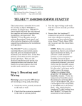
TELSEC® MINI User Guide COPYRIGHT NOTICE Copyright © 2011 by Quest Controls Inc. (QUEST). The material discussed in this publication is the proprietary property of QUEST. QUEST retains all rights to reproduction and distribution of this publication. Specifications are subject to change without notice. Rev 1.1 3/11/11 Table of Contents 1 Overview ............................................................................................................................................... 1 1.1 Getting Started.............................................................................................................................. 1 2 Product Specifications........................................................................................................................... 2 3 Installation ............................................................................................................................................ 3 3.1 Mounting the MINI ....................................................................................................................... 3 3.2 Powering and Grounding .............................................................................................................. 3 3.2.1 Powering the MINI ................................................................................................................ 3 3.2.2 Removing the Battery Insulator ............................................................................................ 3 3.2.3 Grounding the MINI .............................................................................................................. 3 3.3 Connecting the Ethernet ............................................................................................................... 4 3.4 Wiring inputs ................................................................................................................................. 4 3.4.1 Thermistors ........................................................................................................................... 4 3.4.2 Voltage Sensors ..................................................................................................................... 4 3.4.3 Current Sensors ..................................................................................................................... 5 3.4.4 Contact Closures ................................................................................................................... 5 3.5 4 5 6 Wiring Outputs .............................................................................................................................. 6 Local Operation ..................................................................................................................................... 7 4.1 Power LED ..................................................................................................................................... 7 4.2 Alarm LED ...................................................................................................................................... 7 4.3 Relay Outputs................................................................................................................................ 7 4.4 Restoring to Factory Defaults ....................................................................................................... 7 Communicating with the MINI .............................................................................................................. 7 5.1 Connecting to the System ............................................................................................................. 8 5.2 Web Page Navigation .................................................................................................................... 8 5.2.1 The Home Page ..................................................................................................................... 8 5.2.2 Site Information .................................................................................................................... 9 5.2.3 Active Alarms ........................................................................................................................ 9 Programming the MINI ......................................................................................................................... 9 6.1 Web Server Setup ......................................................................................................................... 9 Rev 1.1 3/11/11 6.1.1 IP Address............................................................................................................................ 10 6.1.2 Password ............................................................................................................................. 10 6.1.3 Site Information .................................................................................................................. 10 6.1.4 Saving Information .............................................................................................................. 11 6.2 Setting the System Clock............................................................................................................. 11 6.2.1 Using NTP ............................................................................................................................ 12 6.2.2 Daylight Savings .................................................................................................................. 12 6.3 Alarm Dispatch Settings .............................................................................................................. 12 6.3.1 Global Settings .................................................................................................................... 12 6.3.2 Email Specific Parameters ................................................................................................... 14 6.3.3 SNMP Specific Parameters .................................................................................................. 14 6.3.4 Saving Alarm Dispatch Information .................................................................................... 14 6.3.5 Testing Email Addresses...................................................................................................... 14 6.4 Defining Inputs ............................................................................................................................ 15 6.4.1 6.5 Define Alarms.............................................................................................................................. 17 6.5.1 7 Input Status ................................................................................................................................. 20 7.1.1 Digital input timers.............................................................................................................. 20 7.2 Alarm Point Status ...................................................................................................................... 21 7.3 Active Alarms .............................................................................................................................. 21 7.4 Alarm History .............................................................................................................................. 22 7.5 Log Data ...................................................................................................................................... 23 TFTP Program Upload ......................................................................................................................... 24 8.1 TFTP Commands.......................................................................................................................... 24 8.1.1 Command Format ............................................................................................................... 24 8.1.2 Example program lines: ...................................................................................................... 25 8.2 9 Adding/Modifying an Alarm Point ...................................................................................... 17 Reviewing Status ................................................................................................................................. 19 7.1 8 Change Input Page .............................................................................................................. 15 Uploading a File........................................................................................................................... 26 SNMP Traps ......................................................................................................................................... 27 9.1 TRAP OIDs ................................................................................................................................... 27 9.2 Trap Variable Bindings ................................................................................................................ 27 Rev 1.1 3/11/11 10 Polling the MINI .............................................................................................................................. 28 10.1 11 MIB Tables................................................................................................................................... 28 10.1.1 Mib-2 System Variables ...................................................................................................... 28 10.1.2 Input Table .......................................................................................................................... 28 10.1.3 Extended Input Table .......................................................................................................... 29 10.1.4 Alarm Point Table................................................................................................................ 29 10.1.5 Extended Alarm Point Table ............................................................................................... 30 Troubleshooting .............................................................................................................................. 31 11.1.1 Power Up............................................................................................................................. 31 11.1.2 Communication ................................................................................................................... 31 11.1.3 Sensor Reading.................................................................................................................... 31 11.1.4 Control Point Failure ........................................................................................................... 31 11.1.5 Alarm Notification Failure ................................................................................................... 32 11.1.6 Battery................................................................................................................................. 32 11.1.7 Defining Inputs .................................................................................................................... 32 11.1.8 Defining Alarm Points ......................................................................................................... 32 Appendix A – Setting a Temporary IP Address ........................................................................................... 33 Rev 1.1 3/11/11 1 Overview Quest TELSEC® MINI is designed to provide advanced monitoring and control for very small remote facilities and cabinets using industry standard communications protocols for alarming such as SNMP traps and Emails over Ethernet. The system has a built in web server for status review and programming and can be polled using SNMP Gets. The MINI has six universal inputs for monitoring temperature, humidity, contact closures and any 0-6 VDC or 0-20 mA sensors. The system also has two digital outputs that can be actuated based upon user programmable events. Each sensor may be scaled and displayed in the proper engineering units. This user guide is intended to provide basic operational information for programming and status review. 1.1 Getting Started The TELSEC MINI is simple to setup and program to allow you to start monitoring your facility quickly. The basic steps are listed below along with a chapter reference for this manual: 1. Mount the MINI in the desired location (section 3.1) 2. Power the system. (section 3.2.1) 3. Connect the inputs to be monitored to the system. (section 3.4) 4. Wire the outputs if they are to be used. (section 4.3) 5. Connect the MINI to an Ethernet switch and configure the IP settings. (section 5.1) 6. Define the inputs. (section 6.4) 7. Define the alarm points. (section 6.5) 8. Configure the alarm distribution. (section 6.3) Rev 1.1 3/11/11 -1- TELSEC MINI User Guide 2 Product Specifications Specifications Part number: 150963 Inputs: 6 universal inputs, 0-5VDC, 0-20 MA, thermistor and contact closure. Temp sensor accuracy: ± 1 F Digital Outputs-: 2 form C outputs. Contact Rating: .5amp @ 60VDC Power: 18-65VDC, (50 mA at 48VDC max) Input voltage is monitored and can be used for alarming high and low voltage Network interface: Ethernet 10 Base-T RJ45 connector, with built-in web server. IP protocols supported: HTTP, SMTP, SNMP (v1, v2c) Gets, Traps and Informs, TFTP, NTP Logging: Logs all inputs and alarms. I/O terminal: fixed Power Terminal: two-piece pull off. Battery: Long Life Lithium Ambient operating Temp: -20 to 180 F (-29 to 82 C), 0-95 %Non-condensing Dimensions: 3.5 W x 6 L x 1.25 H in. (89 x 152 x 32 mm) Weight: 0.5 lb (227 g) Warranty: 1 Year Specifications subject to change without notice Rev 1.1 3/11/11 -2- TELSEC MINI User Guide 3 Installation The TELSEC MINI is designed for wall or rack mounting. Rack mounting can be accomplished by flush mounting the unit to a flat crossbar or if space is tight in the rack, you can use Quest’s TELSEC MINI Shelf (pn 140545) to obtain a 1U mounting of the system. 3.1 Mounting the MINI Install the MINI in the desired location using #8 hardware to connect the two mounting tabs to the wall or rack crossbar. 7.4" 6.9" 3.6" Figure 1 - TELSEC MINI Dimensions 3.2 Powering and Grounding 3.2.1 Powering the MINI Follow all National and local electrical codes when powering the MINI. Quest recommends a minimum 18AWG conductor for powering. The TELSEC MINI will operate form 18-65 VDC power (50 mA max at 48 VDC). The power input is isolated from the rest of the system and will work on either a positive or negative DC system. Connect the power to the MINI observing the polarity markings on the enclosure. Reverse polarity will not damage the unit, but it will not operate until corrected. It is recommended that all input wiring be completed with no power to the system. Turn on power once all input wiring is verified. 3.2.2 Removing the Battery Insulator The MINI is shipped with an insulator to keep the battery disengaged from the system. Remove the insulator by pulling the tab in the upper right corner. The system uses the battery to save the system time, log data and alarm history during power failures. 3.2.3 Grounding the MINI There is a ground post on the left side of the TELSEC MINI Chassis. Place a ground wire using a Minimum 12 AWG conductor from the Electrical panel ground bus (or other approved grounding point) to the Rev 1.1 3/11/11 -3- TELSEC MINI User Guide ground terminal on the MINI. Follow national and local codes and practices for properly grounding the system. 3.3 Connecting the Ethernet Use a standard Cat 5 Ethernet cable to connect the MINI to the local switch or hub. Configure the switch port to auto baud detect and auto negotiation. A green LED link light will be illuminated when a physical link has been established. 3.4 Wiring inputs There are two terminals for each of the six user configurable inputs. The plus (+) terminal is the actual input to the unit and the negative (-) terminal is a ground reference. The MINI does not provide power for sensor operation thus any device requiring power will need an external power source to operate properly. The inputs will support any sensor that is a 10k Type III thermistor: 0-6 VDC or 0-20 mA analog sensors. In addition the system accepts dry contact closures or wet contact closures up to 65 VDC. 3.4.1 Thermistors Thermistors are resistive devices and do not have polarity. Connect one lead to the positive terminal of the desired input and the second lead to negative terminal. Quest recommends using shielded cable for all analog sensors. Connect the shield of the cable to chassis ground at the TELSEC MINI. Cut the drain wire and isolate the shield at the sensor end of the cable. 3.4.2 Voltage Sensors The TELSEC can read and scale any linear voltage input from 0 to 6 VDC. Sensors requiring power must be externally powered. Contact Quest Controls for the Input Scaling spread sheet to determine the correct number for the Low and High Custom scale factors. Sensor Output 24 VDC Power supply RH TEMP - + Sensor Power Common Ground Reference Figure 2 - Wiring Voltage Sensors Rev 1.1 3/11/11 -4- TELSEC MINI User Guide 3.4.3 Current Sensors The TELSEC can read and scale any linear current input from 0 to 20 mili Amps. An external 249 ohm resistor is required to convert the signal to voltage and will require an external voltage source to power the sensor. Contact Quest Controls for the Input Scaling spread sheet to determine the correct number for the Low and High Custom scale factors. 249 Ohm Resistor Sensor Output 24 VDC Power supply + - Common Ground Reference Sensor Power Figure 3 - Wiring a 4-20mA Sensor 3.4.4 Contact Closures The TELSEC MINI supports dry contact closures or wet contacts up to 65 VDC. A wet contact is an input where there is an external voltage present. A dry contact has no voltage present and the MINI must provide the sensing voltage. The detection point for determining ON/OFF status is greater than 2.8 VDC and less than 0.8 VDC. Both wet and dry input types are connected between the inputs + terminal (The sense point on the MINI) and the negative (-) terminal (ground reference). For Wet inputs the voltage must be between 0VDC and up to +65VDC. Negative voltages are not supported. Make sure to define the input properly for either “Wet” or “Dry” contact closures to ensure correct operation. Rev 1.1 3/11/11 -5- TELSEC MINI User Guide Monitor Switch Figure 4 - Wiring Contact Closures 3.5 Wiring Outputs There are two form C relays available for control of external devices based upon alarm conditions. The relays are energized in their normal operating state. They are de-energized when an associated Alarm Point is true or active or if power is lost to the MINI. This relay configuration creates a “fail on” condition. Place wire between the common and normally open or normally closed terminals for each output on the MINI®. The relays are designed for Class 2 wiring and are rated for a maximum of 1 amp at 24VAC or 30VDC, 0.3 amps @ 60VDC. 1 amp @ 24VAC/30VDC (.3amp @ 60VDC) Figure 5 - Wiring Outputs Rev 1.1 3/11/11 -6- TELSEC MINI User Guide 4 Local Operation 4.1 Power LED Once the TELSEC MINI is installed, powered, and connected with an Ethernet connection, the system will start operation based on the program controlling the unit. Under normal operation the green Power LED will be flashing at one second intervals to indicate the system is operating properly. Occasionally there may be a pause in this operation if the system is saving data to flash memory. If the LED is off for longer than one minute then check the power connection and then cycle power to the unit. If the LED is constantly on longer than a minute then cycle power to the system to see if it goes back to normal operation of flashing the LED. 4.2 Alarm LED The red alarm LED will be illuminated when any of the alarm points are in alarm. This LED does not provide notification of the state of the control relays since an alarm point may be in alarm, but not associated with an output. If this LED is illuminated, then log into the web server on the MINI and review the active alarm log on the home page. 4.3 Relay Outputs The relay outputs are energized under normal conditions and de-energized when the system does not have power or when an Alarm Point associated with the relay is active (in alarm). The normally open/normally closed terminations on the board refer to this “normal” operating state. There are two outputs that may be associated with any or all alarm points. The logic is such that when any associated Alarm Point is active, the relay is de-energized and will remain in that state until all associated Alarm Points are cleared (no longer active). The output(s) can be used to notify other equipment of alarm conditions or to turn on and off equipment at the site based upon alarm conditions. For example: turning on an exhaust fan if the temperature exceeds a threshold. 4.4 Restoring to Factory Defaults The TELSEC MINI has a small access hole on the right side for the cold start switch. Holding this switch in for 5 seconds after during and after power up will cause the system to go back to all of the factory defaults. During the Cold Start process, you will see both the power LED and Alarm LED flash simultaneously every second. After the five seconds, the power LED will be solid and the alarm LED will be out. Once the cold start is completed, the system will return to normal operation with the power LED flashing. 5 Communicating with the MINI Connect a standard Ethernet cable between the TELSEC MINI and to your local Ethernet switch or router. You can also direct connect to the system with your PC using a crossover Ethernet cable and setting a static IP address on your PC. The MINI has a default IP address of 192.168.1.31. Use this address to log into the unit and then change the IP address to a new permanent setting if required. See Appendix A for information on setting a temporary IP address if you are unable to use the default IP address. Rev 1.1 3/11/11 -7- TELSEC MINI User Guide 5.1 Connecting to the System The built-in web server uses a username and password combination to authenticate a user and allow access. No information will be shown without proper authorization. The default username is User and the password is user. The username and password are case sensitive so make sure your caps lock key is turned off. In addition to the user password, there is an Administrator password that must be entered in order to gain access to any Admin functions such as programming alarms and configuring communications. The default Administrator username/password is Admin and admin. Figure 6 - Log in Screen 5.2 Web Page Navigation Upon initial log into the web server, the MINI will present the Home Page. All pages use frames where the top and left navigation side remains the same and the center section changes depending on the screen requested. This minimizes the amount of data that has to be sent to display the chosen page. All available page choices will be listed in the blue navigation bar on the left of the page. On some pages you have the option of an additional link in the center section for action specific to the data you are reviewing. An example would be a link to download the Alarm Log while reviewing the Active Alarm page. All pages are static, but the values are current (real time) readings when you select the link. To update a page, click on the link again. This causes your browser to request the current status. 5.2.1 The Home Page After you log in with your username and password, the MINI will display the Home page. This page can also be displayed if you click on the HOME link or at any point that you press the Refresh button on your browser. The home page will show Active Alarms and Site Information. See Figure 7 - The TELSEC Home Page. Rev 1.1 3/11/11 -8- TELSEC MINI User Guide Figure 7 - The TELSEC Home Page 5.2.2 Site Information A teal colored box is provided to put site specific information such as the site name, address, phone number and contact number. In addition, a user programmable Universal Record Locator (URL) is available to allow you to link to another web page. This might be a maintenance page, directions to the facility via a mapping site, or connectivity to other Ethernet enabled devices such as web cameras. This information gets programmed through the Web Server Setup page (see Figure 8). 5.2.3 Active Alarms The table on the Home page is Active Alarms. Any active alarm conditions are also displayed on the main page. Alarms are color coded based on severity. Critical alarms are shown in red, major alarms are shown in orange and minor alarms are shown in yellow. If the page doesn’t display any alarms under the Active Alarm header there are no alarms present in the MINI. 6 Programming the MINI Programming the MINI consists of setting the IP address, setting the system clock, configuring the alarm dispatch, defining the inputs and programming the alarm configurations. This section will provide detailed information on these steps to properly configure your MINI system. 6.1 Web Server Setup The Internal Settings link is used to display the current configuration for the MINI’s web server and Ethernet connectivity. This page is used by the system administrator to set the IP and site specific information for the system. Refer to Figure 8 for the fields described in this section. The system will present a username/password prompt if you previously have not entered the Administrator level password (or have not configured your browser to store that information.) Rev 1.1 3/11/11 -9- TELSEC MINI User Guide Figure 8 - Web Server Setup 6.1.1 IP Address The TELSEC supports DHCP to get an address assigned automatically or you can enter in a Static IP address and appropriate information. If you use DHCP, the system will request and address from your server. If no DHCP activity is detected, the TELSEC will default to what is loaded in the static settings. For a static address, enter the IP address, subnet mask, gateway address and DNS server address (if using domain names for SMTP and NTP). Additionally, the setup page allows you to change the IP port number for web browser. Port 80 is the default HTTP port and should only be changed if you require a different port number for your network scheme. 6.1.2 Password The password field is case sensitive and is used to change the username and password for logging into the TELSEC system. The default values for the User realm are User for the username and user for the password. The Admin realm username and password are Admin and admin. Note: the Password and Confirm Password fields will not echo the characters you typed. 6.1.3 Site Information This section is used to enter site specific data that appears on the HOME page in the teal box. Additionally the Site ID field will be displayed in the top section (mast area) of all MINI web pages (as well as email and SNMP alarm messages.) Enter the site identification to be displayed in the ID field. In the Info box enter any site specific data you want displayed on the HOME Page. Items such as the address, site phone number, and contact person are entered in this section. The URL name is a user programmable field where you can enter a description of the hyperlink displayed in the teal box. The final field is the actual URL address. Enter it exactly as required to access the site. The best way to do this is to open a separate browser window, navigate to the desired location and then copy the address Rev 1.1 3/11/11 - 10 - TELSEC MINI User Guide from the address bar to this box. Examples of links would be directions to the facility, other IP connected devices such as a network camera page, or a maintenance log page. 6.1.4 Saving Information After entering the appropriate information you must click on the SAVE button for your changes to take effect. All changes will be discarded if you navigate away from this page without saving. When you click on the SAVE button, the system will accept your changes and then present a “system restarting, reconnect in N seconds” message (N may vary based on the different settings.) Note if you change the IP address to another subnet, the system will be unable to send the restarting message. Your browser will timeout and show an error page. Reconnect to the MINI at the new IP address after waiting at least 60 seconds. If the same page appears after pressing SAVE, then one of the fields you entered was not accepted. Correct the error and resubmit the changes. NOTE: If you have accessed the MINI using a cross-over cable and your laptop, you must change your laptop static IP settings to compliment the new address of the MINI. For example, if you set the TELSEC to address 10.10.10.51 with a subnet of 255.255.255.124 and gateway of 10.10.10.50, then you must assign your laptop to an address close to the TELSEC address to continue to communicate (you could use 10.10.10.50 for your IP with the same subnet). 6.2 Setting the System Clock The Set Clock link allows you to set the MINI system clock. The system will present a username/password prompt if you previously have not entered the Admin password. The clock is used to time and date stamp all alarms and historical log entries. There are drop down boxes for setting the date and time as well as the time zone. You must click on the SET button to send the changes to the MINI. Figure 9 - System Clock Rev 1.1 3/11/11 - 11 - TELSEC MINI User Guide 6.2.1 Using NTP The MINI supports Network Timing Protocol (NTP) as an option. If you have access to an NTP server then enter either the IP address or domain name of the NTP server. To use the domain name, you must have entered a DNS IP address on the Internal Settings page. 6.2.2 Daylight Savings The MINI will automatically adjust for Daylight Savings. The default is to have DLS on to the current US definition. You can change these settings using the dropdown boxes. To turn off DLS, select the word NONE in the “Week” drop down box in the “DST On Point” section and also in the “DST Off Point” section. 6.3 Alarm Dispatch Settings This page is used by the administrator to setup the alarm dispatching of the MINI system. The system will present a username/password prompt if you previously have not entered the Admin level password. The MINI can send alarms via Email and/or SNMP. This page will allow you to setup the global parameters and then the specific locations and filters for sending alarms. Refer to Figure 10 for configuring the alarm dispatching. Figure 10 - Alarm Dispatch 6.3.1 Global Settings The global settings are used by all of the specific address parameters when sending the alarms. These settings must be entered so the TELSEC will know how to deliver the alarms. Rev 1.1 3/11/11 - 12 - TELSEC MINI User Guide 6.3.1.1 SMTP Server Name or IP Address The TELSEC uses Simple Mail Transport Protocol (SMTP) for sending emails to the appropriate people. Enter the IP address of the SMTP server so the TELSEC can send the emails for deliver. The system will support a DNS name or an IP address. If using a name, make sure you enter a DNS server address under the Web Server Setup page (Figure 8 - Web Server Setup). 6.3.1.2 SMTP Port The default SMTP port number is 25; however some email servers may require a different port number. This field allows you to change the port number to the required number for your server. 6.3.1.3 SMTP Authentication Some mail servers require a username and password to log in prior to sending the email. Enter the username and password in the appropriate fields if required, otherwise leave the fields blank. Note the web page will not display the characters you enter in the password field. 6.3.1.4 Email “From” Address Enter the email From address for the MINI. This address is typically the Site ID@<domain name>. Example: [email protected]. Try to pick an address that will be unique for this site so the people receiving the email will be able to reference the alarm by the From Address. 6.3.1.5 SNMP Version The TELSEC system supports sending alarms via SNMP traps in either v1 or v2c. Select the version your trap alarm receiver will use. 6.3.1.6 Incoming SNMP Port The incoming SNMP port is 161 by default, but can be changed to another IP port number if required. Setting the port number to 0 will cause the system to not respond to any SNMP queries. This in affect turns off the SNMP get function for status. You can still send alarms via SNMP, but the system will not respond to queries. 6.3.1.7 Outgoing SNMP Port The default outgoing IP port number for traps is 162. You can change this to another port number if your trap server requires a different port number. 6.3.1.8 SNMP Community The community variable is used for SNMP gets (reads) and sets (writes). This variable needs to match with your SNMP server in order to allow access to the system. The TELSEC uses the same variable for gets and sets. 6.3.1.9 Outgoing SNMP Type The TELSEC supports either Trap or Inform notifications when sending alarms via SNMP. If you select Informs, the TELSEC expects to get a response back from the trap receiver confirming the receipt of the alarm message. The TELSEC will resend the alarm if it does not get an acknowledgement of receipt from the trap receiver. Only select inform if your SNMP trap receiver supports this function. Rev 1.1 3/11/11 - 13 - TELSEC MINI User Guide 6.3.2 Email Specific Parameters This next section is for entering specific data and filters to customize your alarming via email. You can setup for different user groups and specify which alarm types will be sent to each group. 6.3.2.1 Distribution List Each group can contain multiple email addresses. There is room for 120 characters per group. Enter each email address desired and separate them with a semicolon. Make sure you do not add any additional spaces before or after the semicolon used to separate the individual email addresses. Some email servers are very particular, and errors in the distribution list could result in none of the recipients getting email. 6.3.2.2 Subject Field A programmable subject line is available so you can add information you want sent with the alarm message. The subject field in the actual alarm sent will always have the alarm severity followed by the information you program in the subject field. 6.3.2.3 Severity Filter These check boxes allow you to apply filters to only send the appropriate alarm level. CR is for Critical, MJ for Major, MN for Minor, IN for Informational and CL for Cleared alarm conditions. Check the boxes for the alarm severities you want to send. No alarms will be sent unless you check at least one of the severity boxes. 6.3.3 SNMP Specific Parameters The TELSEC can send SNMP traps to four different servers. Each server address can be segregated based upon severity of the alarm. 6.3.3.1 Trap Server IP address Under the Manager IP column enter the IP address of the trap receiver. You need to use an IP number (names not currently supported.) 6.3.3.2 Severity Filter These check boxes allow you to apply filters to only send the appropriate alarm level. CR is for Critical, MJ for Major, MN for Minor, IN for Information and CL for Cleared alarm conditions. Check the boxes for the alarm severities you want to send. No alarms will be sent unless you check at least one of the severity boxes. 6.3.4 Saving Alarm Dispatch Information After you enter the appropriate information you must click on the SAVE ALL button for your changes to take effect. All changes will be discarded if you navigate away from this page without saving first. 6.3.5 Testing Email Addresses The web page has an Alarm TEST button that can be used to send a test email and trap to all programmed addresses. You must save the settings first by pressing the SAVE button and then you can use the test function. Once you have pressed the test button, you can verify that an Informational (IN) test email was sent to everyone in your distribution list. Also verify that a test trap was received at all Rev 1.1 3/11/11 - 14 - TELSEC MINI User Guide programmed trap servers. Correct any errors, press save again and then retest until all test messages are received. Note that SMTP Email servers can often delay the delivery and/or receipt of emails. 6.4 Defining Inputs Click on the Define Inputs link to define the six user programmable inputs. The page will display the current names and settings for each input along with an option to upload a file, download a file and save your changes to flash. The upload option allows you to send a text file using TFTP (tiny file transfer protocol) to program the inputs and alarm points all at once. See section 7. The Download button will download a text file to your browser with all of the input definitions alarm point parameters. Clicking on the current name of an input will bring up the change window and allow you to modify the settings. Click on the “Save to Flash” button after you have made all of your input modifications. Figure 11 - Define Inputs Page 6.4.1 Change Input Page Clicking on the name of the input will bring up the Change input page. Use this page to modify the settings for the input or to clear the timers if the point is defined as a digital. Figure 12 - Change Input Point Page Rev 1.1 3/11/11 - 15 - TELSEC MINI User Guide 6.4.1.1 Point Name The point name will allow up to sixteen characters to describe the point being monitored. The name is case sensitive and will be displayed exactly as you typed it. 6.4.1.2 Sensor Type The sensor type drop down will list the available choices for the input. They are as follows: DRYNO DRYNC WETNO WETNC TEMPF TEMPC CUSTOM A dry contact closure that is normally open. This input will show an OFF value when open and an ON value when closed. A dry contact closure that is normally closed. This input will show an ON value when open and an OFF value when closed. A wet contact closure that is normally open. A wet contact is an input that provides its own voltage. A value greater than 2.8 VDC is determined to be in the ON state and a voltage less than 0.8VDC is deemed to be in the OFF state. The maximum voltage allowed on the input is 65VDC. A wet contact closure that is normally closed. A wet contact is an input that provides its own voltage. A value greater than 2.8 VDC is determined to be in the OFF state and a voltage less than 0.8VDC is deemed to be in the ON state. The maximum voltage allowed on the input is 65VDC. The MINI supports 10k Type III thermistors. Choosing TEMPF will display readings in Fahrenheit. The MINI supports 10k Type III thermistors. Choosing TEMPC will display readings in Celsius. The custom scale allows you to enter your own scale using the Custom Low and Custom High fields. This allows you to create a scale for any sensor that provides a signal between 0-6 VDC or 0-20 milliamps. Note the scale is a linear interpolation between the low and high values. 6.4.1.3 Offset The offset field is used for any analog sensor to correct the reading of the input. The MINI will read the input and add the offset value automatically so all alarms, logging and display screens show the corrected value. The field will accept values from -999 to 9999. 6.4.1.4 Custom Low The Custom Low field allows the user to enter a value when the input is reading minimum value or 0VDC in. The MINI will use this value along with the Custom High value to create a scale and display the sensor in the correct engineering units. The value range is -32767 to 32768 and must be different than the Custom High. 6.4.1.5 Custom High Used in conjunction with the Custom Low field to create a scale for the sensor attached to the input. The High value is the reading the sensor would have if the input is at maximum input value or 6VDC. Quest has created a special Excel spreadsheet for calculating the minimum and maximum values based Rev 1.1 3/11/11 - 16 - TELSEC MINI User Guide on your sensor output. Contact Quest Controls for additional information on what values to use for your specific sensor. The value range is -32767 to 32768 and must be different that the Custom Low. 6.4.1.6 Log Interval This is the logging interval in minutes. The field will allow logging between 1 and 120 minutes for the input. A value of 0 will turn off the logging for the point. Digital inputs are logged based on change of state instead of an interval. Enter a 1 to turn on logging for digital points. Each input has its own log which is approximately 1000 entries. 6.4.1.7 Saving Point Definitions Press the change button to send the new definition to the MINI. The MINI will accept your changes and display the new settings on the Define Input page. You must press the “Save to Flash” button to permanently write all changes to flash once you have completed changing all of your inputs. 6.5 Define Alarms The MINI will allow programming of up to 24 unique alarm points. Each alarm point will create an alarm log entry when the point is true or active. The system will automatically log a Clear condition when the point is no longer true or active for the programmed Clear Delay time. From the Define Alarm Point page you can click on an existing alarm point name to change the program, add a new alarm point (Add New Row), upload a text file using TFTP, download the existing program parameters and save your changes to flash memory. Figure 13 - Define Alarms Page 6.5.1 Adding/Modifying an Alarm Point Clicking on either the name of an existing point or the Add New Row link will bring up the Change point page. Rev 1.1 3/11/11 - 17 - TELSEC MINI User Guide Figure 14 - Change Point Page 6.5.1.1 Point Name The point name is a unique sixteen character maximum name that will be displayed and sent in a message when the point goes into alarm. The name can be upper and lower case alphanumeric characters. There is one special name which is REMOVE. Entering REMOVE (all caps) in the name field will cause that alarm point to be removed from the list of alarm points. 6.5.1.2 Severity The severity drop down will allow you to assign a severity level to the alarm when the point is true. The available options are: CR = Critical alarm displayed in red on the alarm point status and alarm logs. MJ = Major alarm displayed in orange on the alarm point status and alarm logs. MN = Minor alarm displayed in yellow on the alarm point status and alarm logs. IN = Informational alarm displayed in grey on the alarm point status and alarm logs Note: Clear is not a choice because that will be the status of the point when it is not in alarm. Clear alarms display as green on the alarm point status and alarm logs. 6.5.1.3 Input Selection The input drop down will show a list of the inputs with the names that were assigned to them. Each alarm point is unique and multiple alarm points can refer to the same input thereby creating various levels of alarming using different criteria. Select a point from the drop down that you want to use for the alarm point you are creating. 6.5.1.4 Comparison The comparison field is used to compare the status of the input to the value field to the right of the comparison. When this condition is true (for the delay time) then the point is considered in alarm. The available choices are: Greater than, Less than, Equal To and Not Equal To. 6.5.1.5 Alarm Value The Value field next to the Comparison field is where you enter the value you want to compare the input reading to. The field accepts constants from -999999 to 999999. For digital inputs use 1 to equal ON and a 0 to equal OFF. Rev 1.1 3/11/11 - 18 - TELSEC MINI User Guide 6.5.1.6 Alarm Delay There are two fields that make up the alarm delay. They are the Alarm Delay field and the Units field. They are used in conjunction with each other to create a delay time where the alarm point comparison must be true for the delay period. For the Alarm Delay field, enter a constant from 1 to 9999. This value along with the Units field to the right will determine the actual delay time. The Units field is a drop down box and will allow you to choose Seconds, Minutes or Hours. 6.5.1.7 Clear Alarms Once an Alarm Point goes into alarm, it stays in the alarm condition until the comparison statement is no longer true for the Clear Delay time. Once this occurs, a clear event is entered into the alarm history log and a trap and emails will be sent if the system is programmed to do so. There are two fields that make up the clear delay. They are the Clear Delay field and the Units field. For the Clear Delay field, enter a constant from 1 to 9999. This value along with the Units field to the right will determine the actual delay time. The Units field is a drop down box and will allow you to choose Seconds, Minutes or Hours. 6.5.1.8 Nag Interval The TELSEC MINI has a nag feature where if the alarm condition is still present, it will generate another alarm based on this interval. The field accepts values from 0 to 48, which represents the number of hours to wait before sending another alarm. A value of 0 means only send the alarm (trap or email) when the event occurs. A value from 1-48 will cause the system to resend an alarm every time that alarm period is up. For example, a Nag Interval of 1 will cause the system to resend an alarm every hour if the alarm point is still in alarm condition. 6.5.1.9 Output Control The TELSEC MINI has two form C digital outputs that can be used for control of devices such as local warning lights, horn, and exhaust fans or to provide redundant alarming though telemetry overhead. The drop down box will allow you to choose NONE, RLY 1, RLY 2 or BOTH. Multiple alarm points can control the same relay. The MINI will look through all alarm points and turn on the relay point if any of the Alarm Points associated with the relay are active or true. The relay will stay in the on (or active) state until all Alarm Points associated to the Relay are in the Clear condition. 6.5.1.10 Saving Changes Press the Change button once you have entered data in all the fields. Pressing the Change button will send the data to the MINI and bring you back to the Main Define Alarms page. From this point you can modify another existing point or add a new Alarm Point. Press the Save to Flash button after you have made all your changes and additions, to write the program to nonvolatile flash memory. 7 Reviewing Status The TELSEC MINI’s built in web server is designed to provide the user with a simple interface to review the status of points being monitored and assist in diagnosing and troubleshooting problems causing alarm conditions. The Status review screens consist of the Inputs Status, Alarm Point status, Active Alarm log, Alarm History log and the history logging/graphing pages. Rev 1.1 3/11/11 - 19 - TELSEC MINI User Guide 7.1 Input Status The input status page will show the current value of all user programmable inputs and the DC power being measured from the MINI’s input power terminals. Figure 15 shows a typical input status screen where each analog sensor being monitored is displayed in the defined engineering units. Digital input points will show a status (value) of ON or OFF and will have timers automatically associated with the point. Figure 15 - Input Status 7.1.1 Digital input timers Digital input timers are automatically created for an input defined as a Wet or Dry contact closure. The timers start functioning once the point is defined and the timers will retain their values during power failures or resets. The times can be cleared manually from the Define Inputs Detail page for each point. The available timers are as follows: Accumulated ON Interval On Interval Off Event Timer Rev 1.1 3/11/11 This timer counts time when the input is ON and accumulates the total amount of on time for the input. When the point goes off, this timer stops counting, but will start again where it left off once the point goes on again. The display value is in “Days:Hours:Minutes:Seconds”. When the input is ON, this timer starts at 0 and begins counting the on time for this interval. When the input is off, this timer freezes showing the amount of on time during the last on state. The timer automatically resets to zero when the point goes back on and begins counting on time for the new interval. The display value is in “Days:Hours:Minutes:Seconds”. When the input is OFF, this timer starts at 0 and begins counting the off time for this interval. When the input goes on, this timer freezes showing the amount of off time during the last off state. The timer automatically resets to zero when the point goes back off and begins counting off time for the new interval. The display value is in “Days:Hours:Minutes:Seconds”. This timer keeps track of the total time that has elapsed since the timers for this input were cleared. You can use this timer along with the accumulated on timer to calculate percentage on and off time. Or, use this timer with the Event Counter to determine cycling frequency or the number of events that have - 20 - TELSEC MINI User Guide Event Counter occurred in a given time period. The display value is in “Days:Hours:Minutes:Seconds”. The Event counter will increment with every change of state to keep track of the frequency a point is changing. A complete cycle would consist of two (ON/OFF) events. 7.2 Alarm Point Status The Alarm Points link will show the current status of the defined alarm points. Each alarm point will be displayed in color based on alarm severity programmed for the point or in green for clear. Alarm severity colors are: red for critical alarms, orange for major alarms, yellow for minor alarms and grey for informational alarms. The status display will show the programmed severity and the current state which is either Clear or In Alarm. The Timestamp column will show the date and time when the last event occurred, i.e. either when the alarm occurred or the clear. Any point with no timestamp means the TELSEC MINI has never created an alarm event for that point. Figure 16 - Alarm Point Status 7.3 Active Alarms The active alarm link will show basically the same information as the Alarm Points link, but in this case only points that are currently in alarm will be displayed. The points will be displayed in chronological order with the most recent event at the top of the log. Pressing on the Download All Alarms will cause the system to send you a comma separated (CSV) text file of the entire alarm history log. Rev 1.1 3/11/11 - 21 - TELSEC MINI User Guide Figure 17 - Active Alarms log 7.4 Alarm History This link will show the most recent 200 alarms and clear events that have occurred in the system. The alarms are displayed chronologically with the most recent events at the beginning of the log. The data is displayed in groups of 16. Click on the various tabs to scroll through the data or click on the Download All Alarms button to get a comma separated (CSV) text file of all the alarms. Figure 18 - Alarm History Log Rev 1.1 3/11/11 - 22 - TELSEC MINI User Guide 7.5 Log Data The TELSEC MINI logs each input based upon the user defined interval. The system keeps approximately the most recent 1000 entries for each point. The Log Data Link will allow you to review a quick graph based on 6 hour, 24 hour and 7 day intervals. This feature is for analog sensor graphing. Digital inputs log based on change of state thus there may not be any entries for the date range. There is an option to download the entire log for a point in a comma separated (CSV) text file. Select the point you wish to graph and the time range. Then click on show graph to see a graph of the log or the Download File button to get a CSV text file. Figure 19 - Log Graph Display Rev 1.1 3/11/11 - 23 - TELSEC MINI User Guide 8 TFTP Program Upload The MINI can be programmed by uploading a text file using tiny file transfer protocol (TFTP). The text file can contain all or portion of all the available command lines for programming the system. This will make it quicker to program units especially if you are deploying multiple units where the program is essentially the same. A good way to have a standard file is to program a MINI through the web server interface, as described earlier in this manual, and then select the download button from either the Define Inputs or Define Alarms page. This will cause the MINI to download a text file to your PC in the format that the system will accept. You can then modify the file and save it for the specific site or use it as a template for additional sites. 8.1 TFTP Commands The following is a list of commands and format for uploading to the MINI: 8.1.1 Command Format Parameter Code IP Address IP Site Identification ID SMTP data MI SNMP data SI Email list EM Trap Server TS Rev 1.1 3/11/11 Causes Restart Format IP, <[NOT]DHCP>, <IP Address>, <subnet mask>,<gateway>,<DNS ip,”none”>, <http port #> ID,<”Site ID”>, <”URL Name”>, <”URL address”> The URL Name and URL address appear in the blue information box on the home page. MI,<IP number|”name”>, <outgoing port #>, <”from address”>, <”username”>, <”password”> Note: omit the username and password if your email server doesn’t require them. SI,<Trap type 1|2 >, <trap|inform>, <”community string”> ,<incoming port #>,<outgoing port #> EM,<group1-4>,<”Distribution list 120 characters”>, <”subject”>, <[NOT] CR>, <[NOT] MJ>, <[NOT] MN>, <[NOT] IN>, <[NOT] CL> Note: separate email addresses with a semicolon in the distribution list. Make sure there are no spaces before and after the semicolon. Use of the work NOT in front of the severity will prevent alarms with that severity from being sent. TS,<server1-4>, <IP number>, <[NOT] CR>, <[NOT] MJ>, <[NOT] MN>, <[NOT] IN>, <[NOT] CL> Use of the work NOT in front of the severity will prevent alarms with that severity from being sent. - 24 - Yes No Yes Yes No No TELSEC MINI User Guide Clock Settings Define input CS IN CS, <NTP Server ip # |”name”>,<Timezone -11 TO 11>, <DSTON week # 0|1|2|3|4>, <DSTON dow SUN|MON…>, <DSTON JAN|FEB…>, <DSTON time HH:MM>, <DSTOFF week # 0|1|2|3|4>, <DSTOFF dow SUN|MON…>, <DSTOFF JAN|FEB…>, <DSTOFF time HH:MM> Using 0 for the “week” value will turn off the transition point for daylight savings. IN,<1-6>, <”16 char name”>, <DRYNO|DRYNC|WETNO|WETNC|TEMPF|TEMPC|{CUSTOM LOW #,HIGH #}>, <Offset -99 to 99>, <log interval 0-120> AP,<”16 char name”>, <severity>, <input #|name>, <comparison>, <value>, <duration>, <duration time units>, <clear duration>, <clear duration units>,<nag value 0-48>,<output: NONE|RLY1|RLY2|BOTH> Yes No No Severity keywords are: CRITICAL, MAJOR, MINOR, and INFO. Comparison values are: "GREATER THAN", "LESS THAN", "NOT EQUAL TO" and "EQUAL TO". Duration time units are: SECONDS, MINUTES and HOURS Each command starts with a specific two character code to tell the MINI what is going to be programmed. Text labels must be between quotation marks. Available choices for a particular parameter are separated by the pipe (|) symbol. You must choose one of those options when creating a program line. Items in brackets [] are optional. Alarm Point 8.1.2 AP Example program lines: Parameter IP Address Site Identification SMTP data SNMP data Email list Trap Server Clock Settings Define input Alarm Point Rev 1.1 3/11/11 Example Program Line IP, NOT DHCP, 192.168.1.31, 255.255.255.0, 192.168.1.1, 192.168.1.1, 80 ID, "Quest West Coast ", "Directions to office.", "http://tiny.cc/slj56" MI, "smtp.questcontrols.com", 25, "[email protected]", "questcontrols", "quest123" SI, 2, INFORM, "public", 161, 162 EM, 1, "[email protected];[email protected];[email protected];knickel@quest controls.com;[email protected]", "this is a test of the maximum available info in 1", CR, MJ, MN, IN, CL TS, 1, "192.168.1.101", CR, MJ, MN, IN, CL CS, "time.windows.com", -8, 2, SUN, MAR, 02:00, 1, SUN, NOV, 02:00 IN, 1, "Zone Sensor 1", TEMPF, 0, 5 AP, "Zone 1 High CR", CRITICAL, "Zone Sensor 1", "GREATER THAN", 85, 10, SECONDS, 10, SECONDS, 0, RLY1 - 25 - TELSEC MINI User Guide 8.2 Uploading a File To upload a file you must first tell the MINI that you are going to send the file. To do this go to either the Define Inputs page or the Define Alarms page and click on the Upload File button. The MINI will open up the TFTP port (port # 69) and wait up to 5 minutes to receive the file. Next use your TFTP client to send (or Put) the file to the MINI. Windows XP has a built in client accessible from the command prompt. The format for using TFTP at the command prompt is: tftp <ipaddress of MINI> put <filename>. Make sure you do the command from the same directory as where the file is located or provide the full path to access the file. Example: tftp 192.168.1.31 put miniprogram.txt. The MINI will process each line in the file and either accept or reject the line if it is not formatted correctly. The status of the upload will be on the debug page (<IPaddress>/debug.shtml) of the MINI. Some items will cause the unit to restart, but prior to the restart the upload information will be available on debug page. After the upload the MINI will save all new changes to flash and in some cases reboot the system. See the format table above for commands that cause a reboot. Make sure to verify operation of the MINI after you complete your upload especially if this is the first time using a newly created file. Rev 1.1 3/11/11 - 26 - TELSEC MINI User Guide 9 SNMP Traps The TELSEC MINI can send traps or informs to four different trap servers. The user can program the system to send v1 traps, v2 traps or v2 informs to the server. When the MINI sends a trap, it will be sent with an OID based on the severity of the alarm. There will also be multiple variable bindings (varabinds) sent to provide detailed information of the event that occurred. For proper trap reception, you will need the alarmMIB and miniMIB. Please contact Quest Controls for the current revision of both MIBs. 9.1 TRAP OIDs The following table shows the available trap OID names and numbers for each trap type: Alarm Severity OID Number OID Name 11476.100.0.5 Critical alarmCritical 11476.100.0.4 Major alarmMajor 11476.100.0.3 Minor alarmMinor 11476.100.0.2 Info alarmInfo 11476.100.0.1 Clear alarmClear When a point goes into alarm, it will generate a trap using the critical, major, minor or info OID. Once the alarm point goes out of alarm or clears, the MINI will send a trap with the clear OID. 9.2 Trap Variable Bindings The MINI will send the following bindings with every trap that is sent: Varabind Name sysUpTime OID Number 1.3.6.1.2.1.1.3 snmpTrapOID 1.3.6.1.6.3.1.1.4.1 Object Identifier 11476.100.1.3 Text String notifyProduct Value Type Timeticks notifyCriticality 11476.100.1.4 Text String notifyType 11476.100.1.5 Text String notifyTime notifyName notifyValue 11476.100.1.6 11476.100.1.7 11476.100.1.8 Timeticks Text String Text String notifyInputName 11476.100.1.9 Text String notifySiteId 11476.100.1.10 Text String Rev 1.1 3/11/11 - 27 - Value This binding is only available with v2 traps and will contain the system up time since the MINI started up. This binding is only available with v2 traps and will contain the OID value for the alarm severity. The product type that is alarming. For TELSEC MINI’s the value is TELSEC MINI The alarm severity in Text. Available values are: CRITICAL, MAJOR, MINOR, INFO and CLEAR Alarm type. For TELSEC MINI’s the type value is SYS The time the alarm was generated. The sixteen character name of the alarm point The text value of the sensor that caused the alarm. The sixteen character name of the input referenced in the alarm point The programmed site identification value for the system. TELSEC MINI User Guide v1 Trap v2 Trap Figure 20 - Typical SNMP v1 and v2 Trap 10 Polling the MINI The TELSEC MINI supports SNMP polling for some MIB-2 variables along with input status and alarm point status. Please contact Quest Controls to obtain a copy of the current TELSEC MINI MIB file. 10.1 MIB Tables The following tables and values are available; refer to the MIB for more detailed information on each variable: 10.1.1 Mib-2 System Variables sysDescr sysObjectID sysUpTime sysContact sysName sysLocation Read only – current revision of the MINI’s operating system Read only – object identifier for the product and MIB value = MINIMIB Read only – the time since the system started up. Read/Write – contact name or email address. Default is [email protected] Read/Write – the systems name. Default value is: Quest Telsec MINI Read/Write – system location field. Default value is: Telsec MINI 10.1.2 Input Table OID Name miniInputTableIndex miniInputName miniInputNumericValue miniInputCausingAlarm Rev 1.1 3/11/11 Type Description Sequence number of the table for inputs 1-6 plus input 7 Integer dedicated to power monitoring. Text String The sixteen character name assigned to each input. The current value of an input. Digital inputs show 0 and 1 for Integer off and on This value will be a 1 if the input is referenced in an alarm Integer point that is currently active. - 28 - TELSEC MINI User Guide 10.1.3 Extended Input Table OID Name Type miniInputExtendedTableIndex Integer miniInputExtendedName Text String miniInputExtendedNumericValue Integer miniInputExtendedCausingAlarm Integer miniInputExtendedStringValue Text String miniInputExtendedType Integer miniInputExtendedOffset Integer miniInputExtendedCustomLow Integer miniInputExtendedCustomHigh Integer miniInputExtendedLogInterval Integer miniInputExtendeddigitalAccumOn Timeticks miniInputExtendeddigitalintervalOn miniInputExtendeddigitalIntervalOff Timeticks Timeticks miniInputExtendeddigitalEventCounter miniInputExtendeddigitalEventTimer Integer Timeticks Description Sequence number of the table for inputs 1-6 plus input 7 dedicated to power monitoring. The sixteen character name assigned to each input. The current value of an input. Digital inputs show 0 and 1 for off and on This value will be a 1 if the input is referenced in an alarm point that is currently active. The value of the input in textual form. This is useful if the input has a decimal point Shows the input defined type. I.e. dry normally open, temp F, custom etc. The offset programmed for the input Value programmed for custom scales when the input is at the lowest value (0 VDC) Value programmed for custom scales when the input is at the highest value (6 VDC) The user defined logging interval in minutes for the input. For digital inputs this is the accumulated on timer For digital inputs this is the interval on timer For digital inputs this is the interval off timer For digital inputs this is the number of change of states or events. For Digital inputs this is the total time since the input timers have been cleared. 10.1.4 Alarm Point Table OID Name miniAlarmPointTableIndex miniAlarmPointName miniAlarmPointStatus miniAlarmPointSeverity miniAlarmPointLastAlarmTime miniAlarmPointLastClearTime miniAlarmPointInputName miniAlarmPointInputIndex miniAlarmPointInputValue Rev 1.1 3/11/11 Type Integer Description Sequence number of the table for alarm points 1-24 The sixteen character name assigned to each alarm Text String point. Integer Active (1) or Clear (0) of each alarm point The programmed alarm severity value of each alarm Integer point The last time the alarm point went into alarm. A zero Integer indicates the point has never alarmed. The last time the alarm point clear. A zero indicates Integer the point has never cleared. Text String The name of the input assigned to this alarm point The input index number from 1-7 of the input Integer associated with this alarm point Integer The value of the input - 29 - TELSEC MINI User Guide 10.1.5 Extended Alarm Point Table OID Name miniAlarmPointExtendedTableIndex Type Integer miniAlarmPointExtendedStatus Text String Integer miniAlarmPointExtendedSeverity Integer miniAlarmPointExtendedLastAlarmTime Integer miniAlarmPointExtendedLastClearTime Integer miniAlarmPointExtendedInputName Text String miniAlarmPointExtendedInputIndex Integer miniAlarmPointExtendedInputValue Integer miniAlarmPointExtendedComparisonType Integer miniAlarmPointExtendedComparisonValue Integer miniAlarmPointExtendedAlarmDelay Integer miniAlarmPointExtendedAlarmUnits Integer miniAlarmPointExtendedClearDelay Integer miniAlarmPointExtendedClearUnits Integer miniAlarmPointExtendedNagValue Integer miniAlarmPointExtendedOutputs Integer miniAlarmPointExtendedName Rev 1.1 3/11/11 - 30 - Description Sequence number of the table for alarm points 1-24 The sixteen character name assigned to each alarm point. Active (1) or Clear (0) of each alarm point The programmed alarm severity value of each alarm point The last time the alarm point went into alarm. A zero indicates the point has never alarmed. The last time the alarm point clear. A zero indicates the point has never cleared. The name of the input assigned to this alarm point The input index number from 1-7 of the input associated with this alarm point The value of the input The programmed comparator used for the alarm program. I.e. “greater than” or “less than” etc. The value that the input is being compared to for alarm determination The amount of delay that the comparison statement must be true for the point to alarm The type of time units for the delay e.g. seconds, minutes, hours The amount of delay that the comparison statement must be false for the point to clear The type of time units for the delay e.g. seconds, minutes, hours The value in hours before an alarm will regenerate if the condition is still present. Value shows which relay(s) are actuated when the alarm point is true. TELSEC MINI User Guide 11 Troubleshooting The following section is designed to help you isolate the most likely system malfunctions that may occur. For additional help, contact Quest’s Technical Support and Service Center. 11.1.1 Power Up PROBLEM Green Power Light is not blinking every second. SOLUTION 1) Verify you have a power properly applied (18-65VDC). 2) Verify input power polarity. 11.1.2 Communication PROBLEM I experienced a communication failure with the TELSEC® MINI through my Ethernet connection. SOLUTION 1) Verify you have a physical link by looking at the Green LED on the Ethernet jack. Reconnect or replace any defective IP/Ethernet cables. 2) Verify the router the TELSEC®MINI is connected to is operable and properly configured. 3) Verify the IP address has not been changed. Connect to the TELSEC® MINI with a crossover cable and follow the directions in section 5.10 for using the ARP and ping commands. 4) Replace the Ethernet communications module. 11.1.3 Sensor Reading PROBLEM I am not receiving data from one of my sensors. SOLUTION 1) Verify wiring is correct from the sensor to the TELSEC® MINI. 2) Use a known good sensor and replace the suspected bad sensor. 3) If the known good sensor doesn’t work then disconnect the field wiring from the TELSEC® MINI and connect it directly. If it works now then correct or replace field wiring. 4) If the known good sensor doesn’t read when connected directly to the TELSEC® MINI then replace the TELSEC® MINI. 11.1.4 Control Point Failure PROBLEM One of my control points is not turning off. SOLUTION 1) Verify that the program is correct and has the proper Alarm Points assigned to the output. 2) Verify the relay on the TELSEC® MINI opens and closes when the Alarm Point is active and when it clears. 3) Verify the wiring to the control point is correct 4) Verify the control source voltage (typically an external 24 VAC transformer) is operable and supplying proper voltage. Rev 1.1 3/11/11 - 31 - TELSEC MINI User Guide 11.1.5 Alarm Notification Failure PROBLEM I am not receiving email alarms. SOLUTION 1) Verify network connection. 2) Check the setting in the Email Alarm notification page. 3) Verify the EMAIL SMTP server is operational and that the proper username and password (if required) has been entered. 4) Check for any firewalls and or rule sets preventing emails being sent from the location to the SMTP server. 5) Do a test email by clicking on the Email test button. PROBLEM I am not receiving traps. SOLUTION 1) Verify network connection. 2) Check the settings for the trap server and make sure all the filter boxes are checked. 3) Check for any firewalls and or rule sets preventing emails being sent from the location to the SMTP server. 4) Send a test trap by clicking on the test button. 11.1.6 Battery PROBLEM The system keeps losing history memory and clock settings. SOLUTION 1) Verify the battery insulating tab was removed at install to enable the battery circuit. 2) Power down the system, remove the cover and change the system battery. 11.1.7 Defining Inputs PROBLEM The system won’t accept my changes for an input via the web page. SOLUTION 3) Make sure you are using a unique name for each input. An alarm point can have the same name as an input, but inputs cannot have the same name.. 4) If your using a CUSTOM scale make sure the Low and High Values are not the same. 11.1.8 Defining Alarm Points PROBLEM The system won’t accept additional alarms points I am trying to program via the web page. SOLUTION 5) Verify the alarm point you are programming has a unique name. Alarm points and inputs can have the same name, but alarm points cannot have the same name. 6) Make sure that you have entered a delay value greater than 0 in the alarm delay field and also the clear delay field. The value has to be at least 1 second. Rev 1.1 3/11/11 - 32 - TELSEC MINI User Guide Appendix A – Setting a Temporary IP Address The TELSEC Ethernet module supports the ARP protocol and PING command to set a temporary IP address. You will need to know the physical (or MAC) address of the module in order to use the PING function. The MAC address will be on a label affixed to the TELSEC near the Ethernet port and is also on the configuration sheet shipped with each unit. Use the following procedure to set a temporary address: 1 2 3 4 5 6 Connect the TELSEC to the local hub/switch. Or you can use a crossover cable for direct connection to the TELSEC from your PC instead of going through a hub or switch. Connect your laptop to the same hub/switch. Open up the command prompt window and issue the command IPCONFIG. Verify that your laptop has an IP address in the same subnet as the address you will be assigning to the TELSEC. Use the ARP command to enter the TELSEC IP address into your ARP table. The command is ARP –S <IP address> <MAC address><enter> Example: ARP –S 192.168.0.31 00-90-c2-c4-bb-f7 Type ARP –A and verify that the address is entered in as static. Ping the address by typing ping <IP address> and verify that the TELSEC responds to the ping. This address is temporary; you will need to set the address permanently by completing the rest of the steps. Example: ping 192.168.0.31 Step 4 ARP command Step 5 Review ARP table Step 6 Ping Address Figure 21 - Using the Arp and Ping Commands 7 Open your browser and connect to the new address. Follow the instructions in the Web Server Setup (section 5.1) to complete the programming of a permanent IP address. Rev 1.1 3/11/11 - 33 - TELSEC MINI User Guide