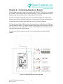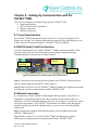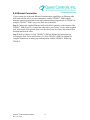
1
Installation Manual COPYRIGHT NOTICE Copyright © 2007 by Quest Controls Inc (QUEST). The material discussed in this publication is the proprietary property of QUEST. QUEST retains all rights to reproduction and distribution of this publication. Specifications are subject to change without notice. Rev 2.0 Dated 9/9/09 Table of Contents CHAPTER 1 – INTRODUCTION ................................................................................................... 3 CHAPTER 2 – PRODUCT DESCRIPTION .................................................................................... 4 2.1 EXTERIOR AND INTERIOR VIEWS OF TELSEC® ESB ........................................................... 4 2.2 SPECIFICATIONS ....................................................................................................................... 6 CHAPTER 3 – MOUNTING THE UNIT ......................................................................................... 7 3.1 CHOOSING A LOCATION .......................................................................................................... 7 3.2 SECURING THE UNIT TO THE WALL........................................................................................ 7 CHAPTER 4 – POWERING THE UNIT ......................................................................................... 8 4.1 CONNECTING THE GROUND..................................................................................................... 8 4.2 MOUNTING THE POWER SUPPLY............................................................................................. 8 CHAPTER 5 – CONNECTING INPUTS, OUTPUTS AND PERIPHERALS ................................ 10 5.1 CONNECTING INPUTS ............................................................................................................. 11 5.2 CONNECTING DIGITAL AND ANALOG OUTPUTS .................................................................. 11 5.3 CONNECTING PERIPHERALS ..................................................................................................... 11 5.4 CONNECTING THE ROOF TOP CONTROLLER (RTU) ........................................................... 12 CHAPTER 6 – CONNECTING EXPANSION BOARDS ............................................................... 13 CHAPTER 7 – CONNECTING CARD ACCESS ........................................................................... 14 7.1 CONNECTING SINGLE CARD READERS ................................................................................. 14 7.2 CONNECTING A 4-PORT CARD READER MODULE ............................................................... 14 CHAPTER 8 – SETTING UP COMMUNICATION WITH THE TELSEC® ESB .......................... 16 8.1 FRONT PANEL INTERFACE ..................................................................................................... 16 8.2 RS232 SERIAL (CRAFT) PORT INTERFACE ........................................................................... 16 8.3 MODEM CONNECTION ........................................................................................................... 16 8.4 ETHERNET CONNECTION ....................................................................................................... 17 TELSEC® ESB Installation Manual Rev 2.0 9/9/09 1 CHAPTER 9 – START UP AND CHECK OUT ............................................................................. 18 CHAPTER 10 – TROUBLESHOOTING, TECHNICAL SUPPORT AND SERVICE .................... 19 10.1 TROUBLESHOOTING ............................................................................................................. 19 10.2 TECHNICAL SUPPORT AND SERVICE ................................................................................... 20 10.3 WARRANTY ........................................................................................................................... 20 TELSEC® ESB Installation Manual Rev 2.0 9/9/09 2 Chapter 1 – Introduction Congratulations on your purchase of the TELSEC® ESB Controller! The TELSEC® ESB is a state-of-the-art electronic monitor and control system that provides you with an integrated surveillance solution for monitoring, control and management of headends, hubs and OTNs. Acting as your smart eyes and ears at the remote site, the TELSEC® ESB is capable of performing your HVAC and lighting control and monitoring, environmental monitoring, power monitoring, generator monitoring, equipment monitoring, intrusion alarming and door access control --- all in ONE product. This Installation Manual is intended to provide the information needed to install the TELSEC® ESB, to highlight the TELSEC® ESB’s features, specifications, and applications, and to discuss the communications options available for communicating with the unit. For information on how to use the system or how to program the unit, please refer to the TELSEC® ESB User Manual or the TELSEC® ESB Programming Manual. Please contact us at Quest if you have product questions or suggestions to improve this Manual. TELSEC® ESB Installation Manual Rev 2.0 9/9/09 3 Chapter 2 – Product Description The TELSEC® ESB is an intelligent, integrated surveillance solution to monitor and control all environmental and access control functions and equipment alarming. The system can be programmed to monitor and automate many facility functions such as lighting, HVAC, power, environmental controls, and interior and exterior building access. The TELSEC® ESB allows for on-site monitoring or remote interrogation from any maintenance or alarm center via serial port (craft port), modem, or Ethernet connections. 2.1 Exterior and Interior Views of TELSEC® ESB TELSEC® ESB Installation Manual Rev 2.0 9/9/09 4 TELSEC® ESB Installation Manual Rev 2.0 9/9/09 5 2.2 Specifications Part Number: 150770 Mounting: Wall mount Inputs: 16 universal inputs expandable to 64 in 16 input increments, (order part# 150155 for Universal Input Expansion Board-UIB) Analog (0-5VDC or 0-20mA) or dry contact closures. Outputs – Digital: 16 digital outputs expandable to 64 in 8 output increments, (order part# 150154 for Digital Output Expansion Board-DOB) Contact Rating: ESB - (16) Form A, 1.0 amp at 30VDC, 0.3 amps at 60 VDC, 0.5 amps at 125 VAC. DOB - (8) Form C, 10 amps at 28 VDC, 8.5 amps at 120 VAC Outputs – Analog Optional: 2 on-board, expandable to 10 analog outputs (order part# 150156 for Analog Output Expansion Board-AOB), 0-10VDC or 0-20/4-20mA Network: RS-485 communications bus for communicating with up to 16 RTU controllers and Input/Output expansion modules (order part# 150440 for RTU) Card Access: Supports industry standard Wiegand format, proximity or card swipe readers. Up to 600 cards can be programmed per site. Logs 800 most recent events. Power: 24V AC or [email protected] amps Front Panel: Built-in programming panel with 18 keys and an 80-character backlit LCD Display Modem: 56K modem Serial Port: DB-9 RS-232 port. Supports asynchronous communications. Programmable for speed, parity, & bit format. Network Interface (option): LAN: Ethernet 10baseT (order part# 300165Q) with RJ-45 connector Protocols Supported: Built-in Web Server, Telnet, HTTP, SMTP (Email), SNMPv1, v2c, Traps/Informs Logging: Logs all inputs, outputs (up to 16,000 points), and alarms (last 99) Software: Supports any off-the-shelf terminal communication software (e.g. HyperTerminal) or Web browser (e.g. Internet Explorer® 6+, Firefox® 1.5+) I/O Terminals: 2 piece pull-off terminals for all field wiring Battery: Long life lithium, 10-year shelf life, 1.5 years under load Temp/Humidity Sensor Accuracy: Temp: ±1°F (±0.5°C), Humidity: ±2% of range, Temperature & Humidity sensors optional (order part# 150749 separately) Ambient Operating Temp: -20 to 180°F (-29 to 82°C), 0-95% RH Non-condensing Certification: UL, CE Dimensions: 12.25"W x 15.25"H x 3.92"D (311mmW x 387mmH x 92mmD) Weight: 14 lbs (6.4 kg) Warranty: One (1) year TELSEC® ESB Installation Manual Rev 2.0 9/9/09 6 Chapter 3 – Mounting the Unit 3.1 Choosing a Location The TELSEC®ESB wall mount enclosure is designed to mount to the wall of any type of facility. The unit should be mounted at eye level in a well-lit, protected area free from excessive vibration and moisture. Usually this is in a maintenance room or other nonpublic location near the circuit breaker panel. Leave sufficient area around the system to allow for routing of conduit and cable. 3.2 Securing the Unit to the Wall Step 1: Using appropriate hardware (#8 x ¾ pan head wood screw or equivalent) fix the top mounting hardware to the wall approximately six feet above the floor, 10.5 inches apart and level. Step 2: Slip the TELSEC® ESB top mounting holes (Figure 1) onto the top mounting hardware and slide down until it stops. Install the bottom mounting hardware in the bottom mounting holes. Figure 1: Location of Mounting Holes and Grounding Studs TELSEC® ESB Installation Manual Rev 2.0 9/9/09 7 Chapter 4 – Powering the Unit The TELSEC® ESB requires 24VAC or [email protected] amps to power the unit. It is also equipped with a long-life lithium battery as a power back up to retain the memory during a power failure (See Section 2.2 Specifications). An example of powering the unit with the 24VAC powering option is discussed in the following sections. Powering the unit with DC power is similar in function. 4.1 Connecting the Ground Step 1: Using terminal lug, run 12 AWG (or larger) ground wire from the TELSEC® ESB ground stud (Figure 1) to the building ground and connect using appropriate hardware. Select the most convenient ground stud; all grounding studs and ground bus are common. 4.2 Mounting the Power Supply If you are not using the Quest Controls Power Supply (Part#300747), you must use a power supply with equivalent specifications. Locate the power supply near the TELSEC® ESB. Ensure that the switches are protected from inadvertent traffic that could accidentally switch the power supply off. Step 1: Remove the two screws that attach the power supply to the back panel mounting plate (Figure 2). Remove screws that attach power supply to mounting plate. RESET 3 A M P OFF RESET OFF Figure 2: Power Supply Mounting Plate Step 2: Tilt the power supply down and slide it off of the plate. Step 3: Screw the back panel mounting plate to the wall using the three holes in the center of the plate (Figure 2). Ensure that a 1/8” gap is maintained between the wall and the plate to allow for power supply tangs to slip into tee slots. Step 4: Using appropriate wire nuts or insulated crimps, make power connection from the power supply circuit breaker. Step 5: Slip tangs into tee slots, tilt power supply up into place on the mounting plate and secure with retaining screws. Step 6: To connect the120VAC input to the power supply, connect the 20a single-phase breaker to the power supply using the appropriate wire (Table 1). TELSEC® ESB Installation Manual Rev 2.0 9/9/09 8 40VA output to ® TELSEC ESB WHT/YEL – 24VAC WHT/BLU – COMMON 120VAC input 75VA output to LCC WHITE – NEUTRAL BLACK – 120VAC GREEN – GROUND WHT/YEL – 24VAC WHT/BLU – COMMON Table 1: Power Supply Wiring Chart Step 7: Connect the low voltage 24VAC power from the power supply’s 40VA output to the TELSEC® ESB input power connector using 18AWG minimum stranded wire (Figure 3). ® Figure 3: TELSEC ESB Connector for Low Voltage Connection Step 8: Label the power supply with the circuit breaker panel designation and breaker number. Step 9: Turn on the circuit breaker to the power supply and all switches on the front of the supply. Verify that the TELSEC® ESB is powered up and the LCD display is lit. TELSEC® ESB Installation Manual Rev 2.0 9/9/09 9 Chapter 5 – Connecting Inputs, Outputs and Peripherals The TELSEC® ESB is configured with 16 universal inputs that accept digital or analog signals, 16 digital outputs, and 2 optional analog outputs for flexible control options. The system is expandable to 64 universal inputs, 64 digital outputs and 10 analog outputs (Figure 4) and is designed for easy installation of a wide array of peripheral equipment to customize your system. Digital Outputs 1-16 Universal Inputs 1-16 Card Reader Expansion Bus Figure 4: Location of Input, Outputs, and Peripheral Connectors TELSEC® ESB Installation Manual Rev 2.0 9/9/09 10 5.1 Connecting Inputs The TELSEC® ESB has 16 universal inputs located on the right side of the logic board (Figure 4). In addition there are 12VDC source voltage terminals available for powering sensors and/or to sense voltage for contact closures. The inputs will accept a 0-6 VDC signal and scale the reading based upon preset engineering factors or allow you to set your own scales. Step 1: Mount the sensor to the physical location to be monitored. Step 2: Using 18AWG wire, connect the input device to the 12VDC terminal and to one of the 16 universal input terminals, depending on which input terminal is assigned to the sensor. To monitor 4-20 mA devices put a 270 Ohm resistor between input and ground reference to convert the reading to voltage. To monitor 10K type 3 thermistor temperature sensors, connect the sensor between input and ground reference. For complete connection instructions, refer to the instruction sheet for the specific sensor. 5.2 Connecting Digital and Analog Outputs Digital Outputs: On the left side of the TELSEC® ESB logic board (Figure 4), there are 15 normally open contacts available for controlling low voltage pilot duty relays using Class 2 wiring. A 16th output is provided with normally open and normally closed contacts. Each relay is rated for 1 amp at 30V AC or DC. Step 1: Connect 18AWG wire to the device being controlled. Step 2: Terminate the wire at the relay terminal assigned to control the device. Analog Outputs: There are two analog outputs on the upper left corner of the TELSEC® ESB board (Figure 4). Each analog output has terminals for providing 0-10 VDC output or 4-20 mA output. These outputs are typically used for controlling dampers, actuators and variable speed drives. Step 1: Decide on either voltage or current output to be used. Step 2: Connect 18AWG wire from the common and either the VDC output or the mA output depending on the device being controlled. For complete connection instructions, refer to the instruction sheet for the specific device. 5.3 Connecting Peripherals A wide array of peripherals is available for the TELSEC® ESB. To install the peripheral(s) ordered with your unit, refer to the installation instruction sheet for that particular peripheral. TELSEC® ESB Installation Manual Rev 2.0 9/9/09 11 5.4 Connecting the Roof Top Controller (RTU) Up to 16 TELSEC® ESB RTUs (Roof Top Unit Controllers) can be easily networked into the TELSEC® ESB system to control multiple air conditioning units for fan, cooling, heating, economizer, and both zone and supply air temperatures. The RTU Controllers network to the TELSEC® ESB by daisy chaining the communications bus (Figure 5) to the TELSEC® ESB Expansion BUS terminals in the lower left corner of the board (Figure 4). To install the RTU, refer to the RTU Installation Manual. Figure 5 - RTU's Networked to the ESB TELSEC® ESB Installation Manual Rev 2.0 9/9/09 12 Chapter 6 – Connecting Expansion Boards Three different expansion boards can be added to the TELSEC® ESB (Figure 6) to expand the TELSEC® ESB’s basic input and output capability: a Universal Input Board (UIB), a Digital Output Board (DOB), and an Analog Output Board (AOB). The Universal Input board (UIB) allows up to 16 individual inputs to be added, these include contact closure and analog inputs as well as an array of sensors and transducers. A maximum of three boards can be added for a total of 64 universal inputs. The Digital Output Board (DOB) and Analog Output Board (AOB) allow for additional control points to be added. The digital board has eight outputs and the analog board has four. A maximum of six DOBs and two AOBs can be added to the system for a total of 64 digital outputs and 10 analog outputs. To install any of these expansion boards, refer to the Expansion Board Installation Manual. Figure 6 - Expansion Boards Networked to the ESB TELSEC® ESB Installation Manual Rev 2.0 9/9/09 13 Chapter 7 – Connecting Card Access ® The TELSEC ESB supports a single card reader directly, or up to four proximity card readers when using the 4-port card reader peripheral. The card reader is connected to the card reader terminals on the lower right of the TELSEC® ESB board. 7.1 Connecting Single Card Readers Step 1: Mount the card reader(s) near the door(s) that is to be controlled. Step 2: Disconnect power to the TELSEC® ESB prior to connection. Step 3: Terminate wires on the keypad prior to terminating at the TELSEC® ESB. Step 4: Connect D0, D1, GND & 12 from the TELSEC® ESB to the same points on each card reader using 4 conductor 20 AWG shield cable (Figure 7). Step 5: Cut and insulate drain wire at the reader and ground the drain wire at the TELSEC® ESB only. Connect the cable from TELSEC® ESB to the same points on the card reader. ESB BOARD Lower Right 1 2 3 4 5 6 7 8 9 0 # Card Access Reader & Keypad Figure 7: Card Reader Connection Terminal on TELSEC® ESB Board 7.2 Connecting a 4-Port Card Reader Module Step 1: Mount the 4-Port Card Reader Module near the TELSEC® ESB. Step 2: Disconnect power to the TELSEC® ESB prior to connection. Step 3: Terminate the wires on the keypad and the 4-port module prior to terminating at the TELSEC® ESB. Step 4: Connect D0, D1, GND and 12V from the 4-port module to the same points on each card reader (Figure 8). Step 5: Using 4-conductor 20 AWG shielded cable, cut and insulate the drain wire at the reader and ground the drain wire at the 4-port module only (Figure 8). TELSEC® ESB Installation Manual Rev 2.0 9/9/09 14 4 PORT CARD READER INTERCONNECT DRAWING FOUR PORT CARD READER MODULE 1 4 7 2 5 8 0 3 6 9 # NOT POLARITY SENSITIVE Card Access Reader & Keypad 1 4 7 2 5 8 0 3 6 9 # + SOL - SOL D1 D0 GND 12V DOOR 1 +R1 -R1 +R2 -R2 +R3 -R3 +R4 -R4 D0 D1 GND NC C1 C2 NC DOOR 4 ESB BOARD Lower Right Power Supply DOOR 3 TO ESB OUTPUTS R1 = DOOR 1, R2 = DOOR 2, R3 = DOOR 3 AND R4 = DOOR 4 A B C DOOR 2 FOR +24VDC POWER CONNECT +24 TO A AND -24 RETURN TO B FOR -48VDC POWER CONNECT +48 RETURN TO B AND -48 TO C + SOL - SOL D1 D0 GND 12V + SOL - SOL D1 D0 GND 12V + SOL - SOL D1 D0 GND 12V Card Access Reader & Keypad 1 4 7 2 5 8 0 3 6 9 # Card Access Reader & Keypad 1 4 7 2 5 8 0 3 6 9 # Card Access Reader & Keypad Figure 8: Connection Drawing for 4-Port Card Reader TELSEC® ESB Installation Manual Rev 2.0 9/9/09 15 Chapter 8 – Setting Up Communication with the TELSEC® ESB There are four methods of communicating with the TELSEC® ESB: Front Panel Interface RS232 Serial (Craft) Port Interface Modem Connection Ethernet Connection 8.1 Front Panel Interface The TELSEC® ESB’s front panel interface consists of a 2-line by 80-character LCD display and a keypad. For complete instructions on using the Front Panel Interface, refer to the section 4.1 Front Panel Interface in TELSEC® ESB User Manual. 8.2 RS232 Serial (Craft) Port Interface You can communicate locally with the TELSEC® ESB by connecting an RS232 cable from the serial (craft) port connection on the unit to a laptop computer and using Terminal Emulation software such as HyperTerminal. Serial (Craft) Port Connection. Dial-up Modem Connection. Ethernet Connection. Figure 9: Bottom Panel of TELSEC® ESB with Connection Ports Step 1: Connect the serial port on the bottom panel of the TELSEC® ESB to the serial port of a laptop using the 9-pin RS232 cable (Figure 9). Step 2: Refer to Section 6.2 of the TELSEC® ESB User Manual for complete instructions on setting up serial port communication with the TELSEC® ESB. 8.3 Modem Connection To communicate with the TELSEC® ESB using the dial-up modem you need an AT command set compatible modem on the other end with communications software to handle the call. Any off-the-shelf package will work. For an approved vendor list, contact your Quest representative. The TELSEC® ESB modem will connect using the highest negotiated speed. Be certain the calling modem is set to use error correction and data compression. Step 1: Connect the telephone cable from the phone jack to the phone port on the TELSEC® ESB (Figure 9). Step 2: Refer to Section 6.2.1 of the TELSEC® ESB User Manual for complete instructions on setting up modem communication with the TELSEC® ESB. TELSEC® ESB Installation Manual Rev 2.0 9/9/09 16 8.4 Ethernet Connection If your system was order with Ethernet Communication capabilities, an Ethernet cable will come with the unit. You can communicate with the TELSEC® ESB using the Ethernet connection and either a terminal communications program such as TELNET or using the TELSEC® ESB’s easy to use Web Server Interface. Step 1: Connect the supplied Ethernet cable to the RJ45 connector on the bottom of the TELSEC® ESB (Figure 9). Connect the other end to your facility’s router in the assigned spot. If the router is not present, then route the cable to the area where the router will be installed and label the cable. Step 2: Refer to Chapter 5 of the TELSEC® ESB User Manual for instructions on accessing the Web Server and Section 6.2.2 of the TELSEC® ESB User Manual for complete instructions on setting up communication with the TELSEC® ESB using TELNET. TELSEC® ESB Installation Manual Rev 2.0 9/9/09 17 Chapter 9 – Start Up and Check Out Once you have installed the TELSEC® ESB and any inputs, outputs, peripherals, or expansion boards, there is a check out process to verify that the TELSEC® ESB is operating properly. Step 1: Ensure that the TELSEC® ESB has power. Step 2: Refer to the checkout list supplied with the unit. Complete as much of the checkout list as possible ( Figure 10). Step 3: Contact Quest Controls to set up an appointment for facility checkout. (This could be an additional charge depending on any agreement in place between the end user/installer and Quest Controls.) Verification List Store #: Location: Date: MECHANICAL/ELECTRICAL CONTRACTOR INFORMATION: Company: Installer Name: Address: City: State: Phone #: Zip: Fax #: Email: QUEST individual assisting with punch down: 1. 2. Bring thermometer for punch down. Contact Quest Controls Monitoring Center to coordinate testing and verification of the system at least 24 hours prior to punch-down. The monitoring center can be reached at (941) 723-4130 or (866) 799-0812. 3. Verify wiring of the RTU per the installation drawings prior to powering the unit. Contact Quest Controls if you are concerned about proper installation. 4. Verify that the TELSEC® ESB, power supply and lighting contactor panels are labeled properly, including location of power source and loads being controlled. 5. 6. 7. Verify wiring for lighting is connected to lighting contactors and is marked with the circuit number. 8. 9. Turn on power to the TELSEC® ESB and verify the front display is showing information, i.e. the system identification and time. 10. 11. 12. Note any changes from the prints on the as-builts, and inform Quest. Make sure the TELSEC® ESB is connected to the stores router (if present) with a Cat 5 Ethernet cable. This procedure assumes the Quest Controls Monitoring Center can communicate with the system. If the network equipment is not present or if the IP address of the unit was not previously set, contact Quest Controls for further instruction. For every HVAC unit verify that the RTU controller board is powered up and displaying a correct zone and supply sensor reading. The display will cycle between zone and supply sensors. The two LEDs next to the display will be illuminated to show which sensor values are displayed. The zone sensor LED is the top one. Contact Quest Controls Monitoring Center at the scheduled time. Take pictures of the wiring for all main components such as the TELSEC® ESB RTU controllers, lighting contactors, and sensor locations. Pictures should be submitted via email to [email protected]. Leave a copy of this form with the rest of the paperwork for the TELSEC® ESB BMS. Punch Down Completed By (Contractor): Telephone Number Figure 10: Sample Verification Checkout list TELSEC® ESB Installation Manual Rev 2.0 9/9/09 18 Date Chapter 10 – Troubleshooting, Technical Support and Service 10.1 Troubleshooting The following section is designed to help you isolate the most likely system malfunctions that may occur. For additional help, contact Quest’s Technical Support and Service Center. PROBLEM The system will not turn on. SOLUTION 1. Verify wiring from the power supply to the TELSEC® ESB. 2. If you’re using DC power, verify polarity. 3. Using a digital voltmeter (DVM) verify the voltage is present at the TELSEC® ESB power terminal inputs. 4. Replace blown fuses and/or power supply if power is not present. 5. Replace TELSEC® ESB if power being supplied is correct. PROBLEM There is no Communication via Ethernet. SOLUTION 1. Verify the Cat 5 cable is connected and that you have a green Link light on at the RJ45 jack. 2. Make sure the IP address programmed is correct or that the router has assigned the correct address via DHCP. Refer to the configuration sheet supplied with the unit for the default IP address. 3. Reset the IP address as needed to match the network settings. PROBLEM The sensor is not reading. SOLUTION 1. Use a DVM to verify the wiring to the controller is correct and that there are no opens or shorts in the wire. 2. Make sure the sensor is defined properly in the systems database. 3. Disconnect the wire going to the Input terminal (IN#) and use a DVM to measure the voltage signal from the sensor. Compare that reading to the expected reading for the sensor based upon its range and verify you are getting the proper range. 4. Move the sensor to another input to check if the input is not functioning. 5. Take a known good sensor and connect it directly to the TELSEC® ESB. If it reads, replace the sensor and or correct any wiring problems with your cable run. TELSEC® ESB Installation Manual Rev 2.0 9/9/09 19 PROBLEM The controlled load won’t turn on/off. SOLUTION 1. Verify the control wiring from the TELSEC® ESB to the pilot relay or device. 2. Use a DVM to determine if voltage is present to the device when the TELSEC® ESB relay turns on. Bypass the relay to turn it on. 3. If everything works when bypassing the point on or off, check the program for proper operation. 10.2 Technical Support and Service For questions regarding technical support, service, or repair of a product, contact us at: Quest Controls 208 9th Street Dr. West Palmetto, FL 34221 Tel: 941-729-4799 To return defective products in or out of warranty, you must have an RMA#. To get an RMA#, call 941-723-4112. For more information about our test and repair center, or about customer support services, visit our website at www.questcontrols.com. 10.3 Warranty QUEST warrants products of its manufacture to be free from defects in design, workmanship and material under normal and proper use and service for a period of 12 months starting upon shipment from the QUEST factory, with the exception of Software noted below. Products not manufactured by QUEST will have a 90-day warranty. Software is warranted to conform to QUEST's Software Product Description applicable at the time of order. QUEST's sole obligation hereafter shall be to remedy any nonconformance of the software to the Software Product Description during the 90-day period following delivery. This warranty shall not apply to fuses, batteries, or any product or parts subjected to misuse, neglect, accident, Acts of God, or abnormal conditions of operation. QUEST agrees to repair or replace, at the place of manufacture and without charge, all parts of said products that are returned to the QUEST factory within the warranty period, provided the warrantor’s examination discloses to its satisfaction that the product was defective and that the equipment has not been altered or repaired other than with QUEST's authorization and by its approved procedures. Repair or replacement of QUEST products does not extend the original warranty period. A product or board may be deemed beyond repair if QUEST determines that it has been subject to misuse, improper maintenance, negligence or accident, damaged or had its serial number or any part thereof altered, defaced or removed. If the failure has been caused by misuse, neglect, accident, or abnormal conditions of operation, or if the warranty period has expired, repairs will be billed at a nominal cost. TELSEC® ESB Installation Manual Rev 2.0 9/9/09 20 This warranty is in lieu of all other warranties expressed or implied, including but not limited to any implied warranty of merchantability, fitness, or adequacy for any particular purpose or use. In no event shall QUEST be liable for any special, incidental, or consequential damages, whether in contract, tort, or otherwise. TELSEC® ESB Installation Manual Rev 2.0 9/9/09 21