1
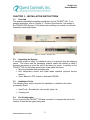
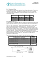
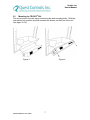
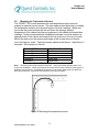
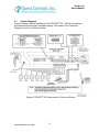
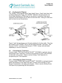
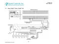
TELSEC® 500
HEAT EXCHANGER CONTROLLER
User’s Manual
Quest Controls, Inc.
208 9th Street Dr. West
Palmetto, FL 34221
www.questcontrols.com
Phone: (941) 729-4799
Fax: (941) 729-5480
Email: [email protected]
TELSEC 500 Manual, V3.0, 9/9/09
TELSEC® 500
User’s Manual
Table of Contents
CHAPTER 1 – INTRODUCTION .......................................................................... 1
CHAPTER 2 – PRODUCT SPECIFICATIONS ..................................................... 2
CHAPTER 3 – INSTALLATION INSTRUCTIONS................................................ 5
CHAPTER 4 – PROGRAM SETUP & CONFIGURATION ................................. 13
CHAPTER 5 – APPLICATION ........................................................................... 20
CHAPTER 6 – OPERATION .............................................................................. 22
CHAPTER 7 – THE FRONT PANEL .................................................................. 25
CHAPTER 8 – SERVICE .................................................................................... 26
APPENDIX A – TEMPERATURE CONVERSION CHART ................................ 28
WARRANTY INFORMATION ............................................................................. 29
TELSEC 500 Manual, V3.0, 9/9/09
i
TELSEC® 500
User’s Manual
CHAPTER 1 – Introduction
Congratulations on your purchase of a new TELSEC® 500 Heat
Exchanger Controller! The Heat Exchanger Controller is a state-of-the-art
electronic monitor and controller providing variable speed control of your heat
exchanger fans and alarming for fan, fuse failure, high temperature and intrusion.
This User’s Manual is intended to provide you with the information you
need to get started with the TELSEC® 500, understand its specifications, how to
install it, how to apply it, how to operate it, and how to service and maintain it.
Please contact Quest Controls if you have questions or suggestions to improve
this User’s Manual.
COPYRIGHT NOTICE
Copyright © 2002-07 by Quest Controls Inc (QUEST). The material discussed in this publication
is the proprietary property of QUEST. QUEST retains all rights to reproduction and distribution of
this publication. TELSEC® & ADAM™ are registered trademarks of QUEST.
Specifications are subject to change without notice
TELSEC 500 Manual, V3.0, 9/9/09
1
TELSEC® 500
User’s Manual
CHAPTER 2 – PRODUCT SPECIFICATIONS
2.1
General
The TELSEC® 500 combines alarming and control functions of heat exchangers
into one package, allowing the user to save money on installation time and save
valuable space inside the cabinet. The TELSEC® 500 provides on/off control as
well as variable speed control of up to six fans. The fans are variable speed
controlled from 40 to 100% duty cycle via PWM techniques. As temperature
inside the cabinet increases/decreases, the fan speed changes proportionally to
maintain proper temperature. The TELSEC® 500 implements pulse width
modulation of the fan motors for variable speed control. The TELSEC® 500
offers the customer four distinct money saving advantages:
1) Utilizing variable speed control of the motors decreases a customer’s
energy consumption needs, which in turn decreases his energy bill.
This also shortens the run time of the fans, increasing the life
expectancy.
2) Variable speed control allows the advanced functionality of reducing
speed during power failure conditions. This increases battery capacity
when necessary. Variable speed also allows reducing the maximum
speed to comply with noise abatement or acoustical requirements.
3) Lower cost 2-wire heat exchanger fans can be used because the alarm
and tachometer functions are built into the TELSEC® 500. This can
result in significant savings in capital expenditures for fans.
The TELSEC® 500 will continuously monitor for fan and fuse failure, and intrusion
alarming. If an alarm condition occurs then the TELSEC® 500 will close an alarm
contact and light the appropriate LED. The alarm contact closure can be tied into
the environmental alarm monitoring system for alarm transportation to the alarm
center.
TELSEC 500 Manual, V3.0, 9/9/09
2
TELSEC® 500
User’s Manual
2.2
•
•
•
•
•
•
•
•
•
•
•
•
Features
Variable Speed or On/Off Control of up to 6 Fans.
Internal Tachometer generator monitors and alarms to user configurable
tolerance range.
Commercial powerfail speed reduction and/or automatic setpoint
adjustment, which saves valuable battery capacity.
User adjustable fan maximum speed clip ensures meeting your tight
acoustical requirements.
User programmable T-stat input sends fans to 100% or 0%. Fail-safe
feature for hazardous conditions.
Override button: turns all motors on full speed and alarms until the system
is reset; override is cleared when cabinet doors are closed.
Fans will run at full speed and an alarm condition will occur if the system
experiences a logic failure or if in override.
An alarm condition will also occur if there is a fuse failure, fan failure, or
the -48VDC power is lost.
Green/Red LEDs for each fan indicate status.
Fan alarm reset: clears alarm conditions manually (on-site).
Supports redundant (dual) power feed from power plant.
Custom rack mounting option available.
Inputs
• Alarms up to 4 intrusion inputs.
• Measures and alarms high temperature condition using 2 external temp
sensors.
• User programmable T-stat input sends fans to 100% or 0%. Fail-safe
feature for hazardous conditions.
• Commercial power fail input takes fans down to lower speed during
battery discharge (extends battery life).
Fan Outputs
• Fan 1 – Fan 6: supplies each fan with -48VDC.
Alarm Outputs
• 1 High Temp: the contacts are wired NO and alarm on contact closure.
• 1 Intrusion: the contacts are wired NO and alarm on contact closure.
• 1 Fan/Fuse: the contacts are wired NO and alarm on contact closure.
Fan Speed Selection
• Fan speed is determined by the TELSEC® 500 based on internal cabinet
temperature.
TELSEC 500 Manual, V3.0, 9/9/09
3
TELSEC® 500
User’s Manual
2.3
Specifications
Part #
Voltage
Current
Alarm Outputs (Contact Rating)
Ambient Operating Range
RS232 port
Terminals & Connections
Fan Type
Dimensions
Weight
Warranty
150663
Nominal 48VDC (44 to 56VDC)
Fused at 2 amp for Module, 7.5 amps/fan at full
speed (up to 45 amps total)
60VDC, 0.3 amps
-40 to 180ºF (-40 to 82ºC)
Configuration and maintenance.
All connections are 2 piece type – plug in
terminal
Compatible with popular industry-standard
ebm/PABST high-velocity fans.
1.95"(50mm) W X 19.1"(486mm) L X
4.4"(112mm) D
3.5 lbs (1.6 kg)
1 year
Specifications are subject to change without notice
2.4
Outputs
The TELSEC® 500 has three alarm and six Fan outputs:
Name
System/Fan/Fuse Alarm
Intrusion Alarm
High Temp Alarm
Fan 1 – Fan 6
Contacts
NO
NO
NO
Function
Closes relay contact on alarm
Closes relay contact on alarm
Closes relay contact on alarm
Supply for the fans.
2.5
Inputs
The TELSEC® 500 has five inputs. The list of inputs and function are as follows:
Name
Contacts
Function
Intrusion
NO
Monitors 4 doors in parallel using normally open
contacts.
T-stat
NO
Programmable to force fans to full or zero speed
with a contact closure.
PFail
NO
Commercial power failure input to reduce fan
speed to preprogrammed minimum speed.
Temp sensor 1
Temperature sensor for on/off or variable speed
control.
Temp sensor 2
TELSEC® 500 will control based upon the highest
reading of both sensors.
TELSEC 500 Manual, V3.0, 9/9/09
4
TELSEC® 500
User’s Manual
CHAPTER 3 – INSTALLATION INSTRUCTIONS
3.1
Overview
This chapter describes the hardware installation for the TELSEC® 500. For a
general description, refer to Chapter 2 – Product Specifications. The design of
the TELSEC® 500 (figures 1 & 2) allows rack mounting in a vertical or horizontal
orientation inside any cabinet.
®
Figure 1. TELSEC 500 front view
Figure 2. TELSEC® 500 back view
3.2
Unpacking the System
A complete system is ready for installation when it is removed from the shipping
carton. This carton and the packaging material should be retained in case it
becomes necessary to return the unit to the factory for repair. In addition to the
TELSEC® 500, the following items will be found inside the carton:
• Mounting hardware and grounding wire.
• One temperature sensor with cable leads standard (optional second
sensor).
• User’s Manual in PDF format on enclosed CDROM.
3.3
Installation Tools
The following items may be required for installation, in addition to the items
provided by Quest:
•
•
Hand Tools - Screwdrivers, wire cutters, pliers, etc.
Crimping tool
3.4
Fan Configuration
Prior to mounting the TELSEC® 500 take a moment to configure the unit for the
number of fans and fan types being used.
TELSEC 500 Manual, V3.0, 9/9/09
5
TELSEC® 500
User’s Manual
3.4.1 Number of Fans
On the back of the unit are two switches that configure the number of fans to be
connected to the system. The switch is located next to the Fan 6 connector.
This needs to be set properly for the fan speed alarms to work correctly. Set
switches as follows:
# Of Fans
Monitor 2 fans
Monitor 4 fans
Monitor 6 fans
Connect To:
FAN 1 & 2
FAN 1-4
FAN 1-6
Switch 1
Down
Up
Up
Switch
2
Down
Down
Up
3.4.2 Setting Fan Type
On the bottom of the TELSEC® 500 is a 6 position dip switch that sets the control
style for each fan connected. There is one switch for each fan corresponding to
FAN 1 to FAN 6 control ports. These switches are used only for 3 and 4 wire
fans to set the proper operation of the control line. Two wire fans are not
affected by the switch position. The following matrix shows the setting for fans
that have been tested by Quest Controls. If your fan is not listed, please contact
Quest Controls, Inc. with the fan specifications to verify a compatible setting prior
to system operation. Improper switch settings may adversely affect the fan
operation and/or life expectancy. Note that “ON” below means the switch should
be pushed towards the back of the can. The location of the dip switch is
illustrated in the figure below.
The following table shows the settings for fans that have been tested:
Switch
Fan Manufacturer and Part #
Position
EBM R1G225-AC73-XX (where XX=36,38,39,52)
ON
EBM R1G225-AF11-XX (where XX=13,14)
OFF
EBM R1G225-AE07-11
OFF
EBM R1G225-AG39-10
ON
EBM R1F250-AQ00-XK
OFF
EBM R1G225-AG15-AA
OFF
TELSEC 500 Manual, V3.0, 9/9/09
6
TELSEC® 500
User’s Manual
3.5
Mounting the TELSEC® 500
The unit mounts to the rack using a mounting clip and mounting bolts. Slide the
rear latches into position and then connect two screws on the front of the unit
(see figure 3 & 4).
Figure 3
TELSEC 500 Manual, V3.0, 9/9/09
Figure 4
7
TELSEC® 500
User’s Manual
3.6
Mounting the Temperature Sensors
The TELSEC® 500 comes standard with one temperature sensor and can
support an optional second sensor. The unit makes control decisions by reading
the temperature sensors and using the higher of the two readings. Make sure
you locate the sensors where the unit will sense the average ambient
temperature of the cabinet and that no equipment in the cabinet will cause false
readings. Quest recommends that installation personnel mount the sensors at
opposite ends of the cabinet and towards the top (such as on the top of a rack.)
Mount the sensors so the sensing end hangs in the air and does not directly
touch the frame or metal. Terminate sensor cables at the Sensor 1 and Sensor 2
terminals. Wire sensors as follows:
Sensor 1 & 2 Connector Wire Color From Cable
Terminal 1
Red wire
Terminal 2
Black wire
Terminal 3
Green wire
Terminal 4
White wire
Terminal 5
Brown wire
See section Control Diagrams for connections.
Note: The temp sensor cable includes a drain wire. Testing has shown that this drain is not
required for installation. Quest cuts this drain wire flush with the cable insulation housing prior to
shipment from the factory. If installation personnel trim the sensor cable length, this drain wire
will become exposed. It should be trimmed back to the cable insulation.
Figure 5: Mounting the temperature sensor
TELSEC 500 Manual, V3.0, 9/9/09
8
TELSEC® 500
User’s Manual
3.7
Control Diagrams
Figure 6 shows a typical installation of the TELSEC® 500. All field connections
are done through two-piece connectors/plugs. See section Fan Connecter
Diagram for pin out of the fan cables.
Figure 6: TELSEC® 500 Interconnect to Fans and Alarms
TELSEC 500 Manual, V3.0, 9/9/09
9
TELSEC® 500
User’s Manual
3.8
Fan Connecter Diagram
The TELSEC® 500 supports either 2 wire “dumb” fans or 3 and 4 wire fans (refer
to section Setting Fan Type). The TELSEC® 500 does the speed control via
Pulse Width Modulation (PWM) and has the ability to create the Tach signal
internally thus allowing the use of lower cost two wire fans. Wiring for a two wire
and four wire fan are shown below.
Figure 7
Figure 8
Figure 7 and 8 shows the pin out of the plug attached to the fan cable. This plug
will connect to the TELSEC® 500 on the fan output terminals 1 through 6. Use
Amp p/n 172167-1 connector with Amp p/n 171639-1 crimps (both provided
separately) for the fan connectors.
3.9
Connecting the T-stat Input
Connect output 1 (Y/G Pair) from the TELSEC® 1500/2000 (or optional external
thermostat) to the T-stat input. Connect to the common (C) and T-stat terminals
on the back of the system. Refer to section Setting T-stat Operation for
programming the T-stat operation.
3.10 Connecting the Power Fail Input
Connect output 2 (Y/BR Pair) from the TELSEC® 1500/2000 (or optional external
power fail contacts) to the Power Fail input. Connect to the common (C) and
Power Fail terminals on the back of the system. Refer to section Setting Power
Fail Speed for programming the Pfail operation.
TELSEC 500 Manual, V3.0, 9/9/09
10
TELSEC® 500
User’s Manual
3.11 Wiring the Cabinet Door Contacts
The TELSEC® 500 has an 8 position Amp connector to monitor door contacts.
The door contacts are Normally Open switches that provide a contact closure
when a door is open. Crimp a pin (Amp p/n 171639-1 provided separately) on
each wire and insert the pins into the connector (Amp p/n 770579-1 provided
separately). Each door contact will have two wires and need to be inserted into
the connector so that 1 wire is on the top and the other wire is directly below it.
See section Control Diagrams for pin outs.
3.12 Wiring Alarm Outputs
The TELSEC® 500 has three alarm outputs which provide a contact closure
when the corresponding alarm condition occurs. When connecting the alarm
contacts to a TELSEC® 1500/2000 wire as follows:
Alarm Contact
Intrusion alarm contact
System/Fan/Fuse Fail contact
High Temp Alarm
Wire To:
White/Brown pair (Input #4)
Yellow/Blue pair (Input #16)
Not connected since the TELSEC®
1500/2000 is sensing cabinet temperature.
3.13 Connecting Power to the Unit
The TELSEC® 500 supports two circuit breaker feeds from the rectifier. Use Amp
connector p/n 53884 (-3 for black, -4 for red) and crimps 53880-4 (both supplied
separately) to connect to the power input. The TELSEC maximum current draw
is 45 amps under normal condition when six fans are being used. Power
conductors should be a minimum #8 AWG. The red connector is the –48VDC
input and the black is the Common.
3.14 Grounding the TELSEC® 500
On the back of the TELSEC® 500 there is a ground wire used to connect the
chassis to Frame ground. Connect the green ground wire to a grounded rack or
frame using ring terminal connector.
TELSEC 500 Manual, V3.0, 9/9/09
11
TELSEC® 500
User’s Manual
3.15 Powering the TELSEC® 500
When the Module has been completely installed, the heat exchanger fans are
plugged in, and fan configuration switch is set, power should be supplied to the
system by turning on the DC power source (both breakers if dual fed). The green
power LED on the front of the TELSEC® 500 will be illuminated with proper
power to the system. On start up, the TELSEC® 500 will go through a selfdiagnostic check and report errors via the front LEDs and the db9 config port.
Refer to section Communicating with the TELSEC® 500 for config port
communications and section Front Panel Operations for front panel operation.
*** WARNING ***
Complete all cable and power connections
before applying –48VDC to the unit
TELSEC 500 Manual, V3.0, 9/9/09
12
TELSEC® 500
User’s Manual
CHAPTER 4 – Program Setup & Configuration
4.1
Communicating with the TELSEC® 500
The TELSEC® has an RS232 port for setting the operating parameters of the
system. All programming is saved to nonvolatile flash memory. To make
changes to the default settings, connect your PC to the system using a db9
straight through cable. Any terminal emulation software can be used to
communicate with the system such as HyperTerminal or ProComm. Set the
communication settings for 9600 baud, 8 data bits 1 stop bit and no parity. With
your PC connected turn the power onto the TELSEC® 500. On power up, the
unit will flash LEDs on the front panel for diagnostics (see section Front Panel
Operations) and then will display the current settings of the system. The display
will look similar to the following:
Quest Controls, Inc.
Telsec 500
Version 2.2.0c
Mode: Variable speed
Fan type: 4 wire
J1 Temp Sensor: OK
J2 Temp Sensor: OK
High Temp Setpoint: 049C
Low Temp Setpoint: 027C
Alarm Temp Setpoint: 063C
High Speed Clip: 00
TSTAT Logic: 00
Pfail Speed: 00
Pfail Temp Increase: 005C
Displaying Status on LEDs for 30 seconds
Performing Initial Fan/Config Check
Entering Control Mode
Password?
4.2
Programming the TELSEC® 500
At the password prompt enter QUEST to gain access to the programming mode.
Note turn on your CAPS Lock key. All input is case sensitive and must be upper
case. If the password is accepted then the system will respond with the current
settings.
Example:
Password? QUEST
Access Granted
Quest Controls, Inc.
Telsec 500
Version 2.2.0c
Mode: Variable speed
Fan type: 4 wire
J1 Temp Sensor: OK
J2 Temp Sensor: OK
TELSEC 500 Manual, V3.0, 9/9/09
13
TELSEC® 500
User’s Manual
High Temp Setpoint: 049C
Low Temp Setpoint: 027C
Alarm Temp Setpoint: 063C
High Speed Clip: 00
TSTAT Logic: 00
Pfail Speed: 00
Pfail Temp Increase: 005C
The system will now allow you access to the Set (S), Review (R) and Write (W)
commands. The Set command is used to change the many different
configurable settings of the TELSEC® 500. The Review command is used to see
the current programming and the status of the temperature sensors. The
sensors will say Error if either the sensor is malfunctioning or no sensor is
detected. An OK will display if the sensor is working properly. The Write
command is used to write your program changes to flash.
4.2.1 Fixed Speed vs. Variable Speed
The TELSEC® 500 can be factory configured for fixed or variable speed control
modes. In variable speed mode, the unit intelligently determines what speed the
fans should optimally run when between the low and high setpoints. In fixed
speed mode, fans are either off when below the low setpoint or on when above
the high setpoint.
It’s important to note that the High Speed Clip and Power Fail Reduction features
are available to the user in fixed speed control mode.
4.2.2 Setting the High Speed Clip
The high speed clip command is used to set the maximum allowable speed of
the fans during normal operation. This feature forces the fans to run at a speed
setting less than 100% to reduce acoustical noise and energy consumption, and
to extend the fan bearing life. This setting is only applicable during normal
temperature control. The fans will run at 100% if one of the following exceptions
occur: the high temp alarm threshold has been exceeded, the T-stat input is on (if
programmed for 100% on see section Setting T-stat Operation) or if the override
button is pressed to turn all fans on. The high speed clip can be set from 100%
(default) to 40% in 10% increments by issuing the following command at the
T500> command prompt:
Format:
S 1 # <enter>
Where # = 0 for 100%, 1 for 40%, 2 for 50%, 3 for 60%, 4 for 70%, 5 for 80% and
6 for 90%.
TELSEC 500 Manual, V3.0, 9/9/09
14
TELSEC® 500
User’s Manual
Example:
S 1 5 <enter>
Sets the clip speed to 80% for normal operation.
Note settings are not saved and used until the Write (W) command is issued.
4.2.3 Setting the Fan Type
The TELSEC 500® supports the operation of either 2 wire (dumb) fans or 4 wire
(smart) fans. There is no loss in functionality or operation when using two wire
fans. The benefit is that typically a comparable two wire fan has fewer
components and thus is cheaper than a four wire fan. Switching to two wire fans
allows the user to reduce the capital cost of the fans. The default mode is 4 wire
fans. This parameter doesn’t need to be changed unless 2 wire fans are being
used. Note that you cannot mix 2 and 4 wire fans on the same controller
because all fans are controlled the same. To change the fan type, use the
following command:
Format:
S 2 # <enter>
Where # = 0 corresponds to 2 wire fans and 1 corresponds to 4 wire fans.
Example:
S 2 0<enter>
Sets the TELSEC® 500 to control 2 wire fans.
Note settings are not saved and used until the Write (W) command is issued.
4.2.4 Setting T-stat Operation
The TELSEC® 500 has an input terminal for an external T-Stat or contact
closure. This input point can be used to make the fans run at 100% or to turn all
fans off depending on how the point is programmed. The input senses a contact
closure and does the corresponding action. When an open is present at the
input, the system will return to normal operation. The default function is to turn
all fans on 100% with a contact closure. A high temp thermostat can be used
inside the cabinet as a backup device to turn the fans on 100%. The full off
function of the T-stat can be used as a way to turn off the fans if a high
temperature condition is experienced outside the cabinet such as a brush fire. In
this application, place the T-stat in the supply air intake to shut the fans down if
the intake air temp becomes extreme. When the T-stat contact is closed, the
high temp alarm LED and high temp alarm contact are active. Use the following
command to change the T-stat operation.
Format:
S 3 # <enter>
Where # = 0 corresponds to 100% speed and 1 corresponds to 0% speed.
TELSEC 500 Manual, V3.0, 9/9/09
15
TELSEC® 500
User’s Manual
Example:
S 3 0<enter>
Sets the T-stat input so a contact closure = 100% speed.
Note settings are not saved and used until the Write (W) command is issued.
4.2.5 Setting Power Fail Speed
The TELSEC® 500 has an input terminal for a power fail reduction contact. A
closure at these terminals puts the unit into power fail reduction mode, where the
fan speed will be clipped to a new power fail speed. This function is particularly
useful to reduce the current draw on the fans during commercial power failure
thus extending the battery plant capacity (time until low voltage disconnect). The
fans will not run faster than this speed unless the T-Stat input is on (see section
Setting T-stat Operation), the high temp threshold has been exceeded or the
override button is pressed. Once the contact closure goes away, the system is
returned to normal operation. Use the following command to set the max speed
during a power failure condition:
Format:
S 4 # <enter>
Where # = 0 for 100% (Default), 1 for 40%, 2 for 50%, 3 for 60%, 4 for 70%, 5 for 80%
and 6 for 90%.
Example:
S 4 3 <enter>
Sets the PFail speed to 60% when called for with a contact closure
Note settings are not saved and used until the Write (W) command is issued.
4.2.6 Setting Power Fail Temperature Increase
The TELSEC® 500 allows an alternate method of reducing speed during
commercial power failure. The unit will offset the high and low setpoints by the
value of the power fail temperature increase. This allows a user to physically
alter the setpoints during power fail conditions instead of just clipping the speed
using the power fail speed value. The units are degrees Celsius. Use the
following command to set the power fail temperature increase:
Format:
S 5 # <enter>
Where # = can be 0 – 20 (in degrees Celsius).
Example:
S 5 8 <enter>
Sets the power fail temperature increase to 8 degrees Celsius.
Note settings are not saved and used until the Write (W) command is issued.
TELSEC 500 Manual, V3.0, 9/9/09
16
TELSEC® 500
User’s Manual
Both the power fail speed and power fail temperature increase options act
independently. This allows maximum flexibility when configuring your TELSEC®
500.
4.2.7 Setting Alarm Temperature Setpoint
The TELSEC® 500 compares the two temperature sensors against the alarm
temp setpoint and chooses whether or not to put the system into high
temperature alarm mode. Once the higher reading of the two temperature
sensors crosses this setpoint, the TELSEC® 500 will make the high temp relay
contacts. When the temperature retreats two degrees under the alarm
temperature setpoint, the unit will take itself out of high temp alarm. The unit will
range check any input temperatures to ensure the alarm setpoint is above the
high temp setpoint. Values from 0 to 99 are accepted, but obviously only a
number corresponding to the maximum allowable temperature in your
environment should be used. The units are degrees Celsius. Use the following
command to set the alarm temperature setpoint:
Format:
S 6 # <enter>
Where # = can be 0 – 99 (in degrees Celsius).
Example:
S 6 70 <enter>
Sets the alarm temperature setpoint to 70 degrees Celsius
Note settings are not saved and used until the Write (W) command is issued.
4.2.8 Setting High Temperature Setpoint
The TELSEC® 500 uses the high temperature setpoint when figuring out what
speed to run the attached fans. This setpoint is the high end of the scale and
reflects the temperature required to send the fans to 100% velocity. The unit will
range check any input temperatures to ensure the high temp setpoint is above
the low temp setpoint and below the alarm temp setpoint. Values from 0 to 99
are accepted, but care should be exercised in finding a setpoint that keeps your
environment within operating specifications and allows the most power savings
possible. The units are degrees Celsius. Use the following command to set the
high temperature setpoint:
Format:
S 7 # <enter>
Where # = can be 0 – 99 (in degrees Celsius).
Example:
S 7 50 <enter>
Sets the high temperature setpoint to 70 degrees Celsius
Note settings are not saved and used until the Write (W) command is issued.
TELSEC 500 Manual, V3.0, 9/9/09
17
TELSEC® 500
User’s Manual
4.2.9 Setting Low Temperature Setpoint
The TELSEC® 500 uses the low temperature setpoint when figuring out what
speed to run the attached fans. This setpoint is the low end of the scale and
reflects the temperature required to stop the fans entirely. The unit will range
check any input temperatures to ensure the low setpoint is below the high temp
setpoint. Values from 0 to 99 are accepted, but care should be exercised in
finding a setpoint that keeps your environment within operating specifications and
allows the most power savings possible. The units are degrees Celsius. Use the
following command to set the low temperature setpoint:
Format:
S 8 # <enter>
Where # = can be 0 – 99 (in degrees Celsius).
Example:
S 8 30 <enter>
Sets the high temperature setpoint to 30 degrees Celsius
Note settings are not saved and used until the Write (W) command is issued.
TELSEC 500 Manual, V3.0, 9/9/09
18
TELSEC® 500
User’s Manual
4.2.10 Reviewing Program Settings
After you have made the necessary changes to the TELSEC® you can review
your settings prior to writing them to flash. Note that the settings are not saved
and acted upon until they have been written to flash. Use the following command
to review current program status:
Format:
R <enter>
Example:
R <enter>
The TELSEC® 500 responds with:
Quest Controls, Inc.
Telsec 500
Version 2.2.0c
Mode: Variable speed
Fan type: 4 wire
J1 Temp Sensor: OK
J2 Temp Sensor: OK
High Temp Setpoint: 049C
Low Temp Setpoint: 027C
Alarm Temp Setpoint: 063C
High Speed Clip: 01
TSTAT Logic: 00
PFail Speed: 02
Pfail Temp Increase: 005C
T500>
4.2.11 Writing to flash
Now that you are satisfied with the changes you can save them to flash memory.
The Write command (W) is used to do this function. The format is as follows:
W QUEST<enter>
The system will respond with:
Writing to Flash and rebooting
Your changes have been written to flash and the system is rebooted. After the
system comes up from the reboot, it will begin to operate based on your new
settings.
Note: If you do not want to save changes you made, then press the reset button
next to the craft port instead of using the Write command.
TELSEC 500 Manual, V3.0, 9/9/09
19
TELSEC® 500
User’s Manual
CHAPTER 5 – APPLICATION
5.1
Overview
Used in conjunction with the TELSEC® 1500/2000 monitoring and control
system, the TELSEC® 500 provides a cohesive system for effective management
of your cabinet. The TELSEC® 1500 supports 16 inputs and 8 outputs and the
TELSEC® 2000 supports 32 inputs and 16 outputs. These inputs and outputs
can be used to monitor and control the environmental conditions of your cabinet.
5.2
TELSEC® 1500 IO Point List
Typical Cabinet with Heat Exchangers
Rev Date: August 15, 2002
DIGITAL INPUTS
1
2
3
4
5
6
7
8
TELSEC 500 T-STAT INPUT (FULL SPEED)
TELSEC 500 COMMERCIAL POWER FAIL INPUT (MIN SPEED)
UNIVERSAL INPUTS
#
1
2
3
4
5
6
7
8
9
10
11
12
13
14
15
16
Input Name
HIGH TEMPERATURE
HIGH HUMIDITY
FLOAT VOLTAGE
INTRUSION - DOOR OPEN FROM TELSEC®
500
BATTERY CIRCUIT BREAKER FAIL
COMMERCIAL POWER FAIL
RECTIFIER FAILURE MAJOR
RECTIFIER FAILURE MINOR
POWER PLANT FUSE
BATTERY LVDC
RACK COOLING FAN FAILURE
TEMP COMPENSATOR UNIT FAIL
UFAP/UFPP SIDE A CIRCUIT BREAKER
UFAP/UFPP SIDE B CIRCUIT BREAKER
UFAP/UFPP FUSE & PDFA FUSE
SYSTEM ALARM FROM TELSEC® 500
TELSEC 500 Manual, V3.0, 9/9/09
20
Sensor Type
TEMP ºF
%RH
VDC power to unit
DRY CONTACT
DRY CONTACT
DRY CONTACT
DRY CONTACT
DRY CONTACT
DRY CONTACT
DRY CONTACT
DRY CONTACT
DRY CONTACT
DRY CONTACT
DRY CONTACT
DRY CONTACT
DRY CONTACT
TELSEC® 500
User’s Manual
5.3
Wiring TELSEC® 1500 to TELSEC® 500
TELSEC 500 Manual, V3.0, 9/9/09
21
TELSEC® 500
User’s Manual
CHAPTER 6 – OPERATION
6.1
Overview
The TELSEC® 500 comes with pre-set factory parameters. These settings can be
reprogrammed with different fan type specifications and set points by loading a
new image into the Flash memory. Contact Quest Controls for your specific
requirements and procedure for upgrading the Flash memory.
6.2
Initial Startup
When the unit comes out of reset, it will perform self-diagnostics. Any possible
input/output or sensor malfunction will be communicated to the user via the front
panel LEDs. See section Front Panel Operations for the error codes.
A fan configuration check will then occur. The unit will increase the fan speed to
100% and monitor the tachometer for each fan. The unit will then compare the
determined fan count with the fan number configuration switch. If fans are
noticed in positions greater than those warranted by the configuration switch (i.e.
fan 5 is determined present but the user has set the configuration switch for only
4 fans), the red LED will light and the system alarm contacts will be made. If the
unit does NOT notice fans in positions where the user has properly configured
them (i.e. fan 2 is NOT present and the configuration switch has been set to 4
fans), the red LED will light and the system alarm contacts will be made.
The unit will then proceed to control mode.
6.3
Normal Control Mode
The TELSEC® 500 varies the fan speed to keep the temperature in the cabinet
between the low and high setpoints. This application is the normal control mode.
•
•
•
•
•
The temperature sensors are read and the maximum temperature used as
input to the control loop.
If the temperature is less than the low setpoint, the fans will be powered
off.
If the temperature is greater than the high setpoint, the fans will be
powered to the high speed clip maximum (default 100%).
In variable speed mode, the fans will step to the desired speed from the
current speed.
If the temperature is between the two setpoints, the unit will interpolate
and determine a proportional speed between 50 and 100%.
TELSEC 500 Manual, V3.0, 9/9/09
22
TELSEC® 500
User’s Manual
6.4
Variations to Normal Control Mode
The TELSEC® 500 strays from the normal control mode when certain
circumstances occur. In decreasing level of priority:
•
Manual Override
If the intrusion input is made, a user can bypass the unit by pressing the
override button. A single press turns the fans all on. A second press
turns the fans all off. A third press releases override mode. When in
intrusion mode, the intrusion relay contacts are made.
•
Tstat Override
If the tstat input is made, the fans will be controlled via the programmed
definition for the tstat. Full on or off is available. When the tstat input is
made, the high temp relay contacts are made.
•
High Temp Condition
If either temperature sensors read above the alarm setpoint, the fans will
turn all on. When the high temp condition exists, the high temp relay
contacts are made.
•
Powerfail Condition
If a closure is sensed at the powerfail input, the TELSEC® 500 maximum
speed will be clipped to the programmed powerfail clip setting. If the unit
happens to be running at a calculated speed less than that number, the
speed will be unchanged.
A closure at this input also applies the programmed powerfail temperature
increase to the low and high setpoints. This allows a user to temporarily
decrease the power requirements during a commercial power failure in
exchange for a higher allowable temperature in the cabinet. The increase
does NOT apply in any way to the alarm setpoint.
6.5
Tachometer Measurement
•
•
The unit contains an onboard tachometer sensing circuit. During any
mode where the fans are running, the unit calculates the tachometer for
each fan and consults an internal table to determine whether or not the fan
is spinning according to specification. This helps diagnose fan failure in
cases of both fan impediments and fan blade breakage. Notice that
tachometer measure is, of course not required when the fan is not
spinning.
When the unit determines a fan is in failure, it will light the corresponding
red LED and make the system alarm relay contacts. If the fan is
subsequently found to be within spec, the corresponding green LED will
be lit. Note that the red LED will continue to be lit under this scenario.
TELSEC 500 Manual, V3.0, 9/9/09
23
TELSEC® 500
User’s Manual
•
6.6
This is so a technician can notice that a fan was in fault at some past time,
but has returned to spec.
The fan alarm reset button can be pushed at any time to clear the red fan
LEDs (and system alarm contact if a fan is still in alarm.) On its next
opportunity, the unit will perform tach calculations and adjust the LEDs
accordingly.
Alarming
All three alarms are wired so when power is not applied to the unit, a closure is
present at all three contacts. When the unit is running correctly, an open will be
present at all three contacts.
•
High Temperature Alarm
These alarm contacts are made and the high temp LED is lit when:
o The unit senses a temperature above the system alarm
temperature.
o The unit senses a closure on the tstat input.
These alarm contacts clear when the above conditions return to
normal.
•
System/Fan/Fuse Alarm
These alarm contacts are made when:
o Any fan is found present in a position where no fan should be
according to the configuration switch. Corresponding red fan
LED lit along with Sys alarm LED.
o Any fan tachometer is out of specification during run mode.
Corresponding red fan LED lit along with Sys alarm LED.
o Any fan fuse is blown. Fuse LED is lit.
o The unit has sensed an internal error.
•
Intrusion Alarm
These alarm contacts are made when:
o The unit senses a closure on the intrusion input.
TELSEC 500 Manual, V3.0, 9/9/09
24
TELSEC® 500
User’s Manual
CHAPTER 7 – THE FRONT PANEL
7.1
Front Panel Operations
The front panel has multiple LEDs to provide a visual representation of system
status. All alarms have a red LED and are illuminated when an alarm is present.
Each fan has a red and green pair of LEDs. A green LED on indicates normal
operation of the fan. A red LED on indicates a problem with that fan. If both the
red and green LEDs are illuminated, the fan is currently operating normally, but
at one time had a speed alarm. By pressing a momentary pushbutton labeled
Fan Error Reset, you can clear alarm status on the fans. The unit will then
redetect any fan alarms and light the appropriate fan LEDs.
The panel has another momentary pushbutton labeled Override. To turn all fans
on 100%, simply press this switch once. To turn all fans off, press the switch
twice. To return control to automatic mode, press the switch a third time. Note
that the override pushbutton only functions when the TELSEC® 500 senses a
cabinet door is open (intrusion alarm). If the intrusion input opens, the unit will
return to automatic control mode.
On start up or if the system reset button next to the db9 config port is pushed, the
front panel LEDs will display in diagnostic mode to indicate any problems with the
temperature sensors or controller. The following table details the various status
codes:
Condition
Two valid sensors found
Sensor 1 valid and sensor 2
invalid
Sensor 1 invalid and sensor
2 valid
No valid sensors
TELSEC 500 Manual, V3.0, 9/9/09
Override
On LED
On for 30
seconds
On for 30
seconds
On for 30
seconds
Constant
flash
25
Override Off
LED
Flash 3 times
every 5 seconds
Flash 1 time
every 5 seconds
Flash 2 times
every 5 seconds
Constant flash
Action
Go to run mode
after 30 seconds
Go to run mode
after 30 seconds
Go to run mode
after 30 seconds
System fail mode
with code 3 (fan 5
and 6 LED on)
TELSEC® 500
User’s Manual
CHAPTER 8 – SERVICE
8.1
Troubleshooting
No LED’s are illuminated:
1. Is the power plug connected?
2. Is the power fuse (#7) blown?
3. Is power being supplied by the rectifiers or batteries?
Override On/Off LED is red: 1. Press override button 2 times if fans are on and 1 time if
fans are off.
2. Shut the cabinet doors.
Alarm LED is red:
1. Is the LED labeled Fuse red? If yes replace the blown
fuse and depress the Fan Error Reset button.
2. Are any of the Fan1-Fan6 LED’s red? If yes first check
the fuses and make sure none are blown. If blown
replace and depress the Fan Error Reset button. If no
fuses are blown depress the Fan Error Reset button.
Replace defective motor if the LED is still red or turns red
after 30 seconds.
The FUSE LED is red:
1. Are any of the fuses blown? If yes replace blown fuse
and depress Fan Error Reset button.
A Fan1-Fan6 LED is red:
1. Depress the Fan Error Reset button. This will restart the
monitor sequence. Wait a couple of minutes to see if the
LED goes red again. If still red (or goes red) then swap
with a known good fan position an press reset. If the
problem follows the fan then replace the defective motor.
If the problem is still present on the same input with a
known good fan then replace the TELSEC® 500.
High Temp LED is red:
1. Determine if a high temperature condition is present.
2. Verify that the T-stat input is not sensing a contact
closure.
TELSEC 500 Manual, V3.0, 9/9/09
26
TELSEC® 500
User’s Manual
8.2
Return of TELSEC® 500 for Repair
If all troubleshooting and technical support alternatives (including troubleshooting
over the phone with Quest service staff) have been exhausted and it is deemed
by Quest that the unit should be returned for repair, please do the following:
1. Call Quest at 941-729-4799 to receive your RMA# (required for shipping
back): Ask for the Service Department.
2. With the RMA#, please document the symptoms or problem you were
experiencing. This will aid in repairing the unit.
3. Ship back to Quest:
Repair Depot
Quest Controls Inc.
208 9th Street Drive W.
Palmetto, FL 34221
TELSEC 500 Manual, V3.0, 9/9/09
27
TELSEC® 500
User’s Manual
Appendix A – Temperature Conversion Chart
We’ve provided this chart to assist in the conversion of Fahrenheit and Celsius.
°C
°F
°C
°F
°C
°F
°C
°F
0
1
2
3
4
5
6
7
8
9
10
11
12
13
14
15
16
17
18
19
20
21
22
23
24
32.0
33.8
35.6
37.4
39.2
41.0
42.8
44.6
46.4
48.2
50.0
51.8
53.6
55.4
57.2
59.0
60.8
62.6
64.4
66.2
68.0
69.8
71.6
73.4
75.2
25
26
27
28
29
30
31
32
33
35
36
37
38
39
40
41
42
43
44
45
46
47
48
49
50
77.0
78.8
80.6
82.4
84.2
86.0
87.8
89.6
91.4
95.0
96.8
98.6
100.4
102.2
104.0
105.8
107.6
109.4
111.2
113.0
114.8
116.6
118.4
120.2
122.0
51
52
53
54
55
57
58
59
60
61
62
63
64
65
66
67
68
69
70
71
72
73
74
75
76
123.8
125.6
127.4
129.2
131.0
134.6
136.4
138.2
140.0
141.8
143.6
145.4
147.2
149.0
150.8
152.6
154.4
156.2
158.0
159.8
161.6
163.4
165.2
167.0
168.8
77
78
79
80
81
82
83
84
85
86
87
88
89
90
91
92
93
94
95
96
97
98
99
170.6
172.4
174.2
176.0
177.8
179.6
181.4
183.2
185.0
186.8
188.6
190.4
192.2
194.0
195.8
197.6
199.4
201.2
203.0
204.8
206.6
208.4
210.2
To convert from Fahrenheit to Celsius: (°F – 32) / 1.8 = °C
To convert from Celsius to Fahrenheit: (°C x 1.8) + 32 = °F
TELSEC 500 Manual, V3.0, 9/9/09
28
TELSEC® 500
User’s Manual
WARRANTY INFORMATION
QUEST warrants products of its manufacture to be free from defects in design, workmanship and
material under normal and proper use and service for a period of 12 months starting upon
shipment from the QUEST factory, with the exception of Software noted below. Products not
manufactured by QUEST will have a 90-day warranty. Software is warranted to conform to
QUEST's Software Product Description applicable at the time of order. QUEST's sole obligation
hereafter shall be to remedy any nonconformance of the software to the Software Product
Description during the 90-day period following delivery. This warranty shall not apply to fuses,
batteries, or any product or parts subjected to misuse, neglect, accident, Acts of God, or
abnormal conditions of operation.
QUEST agrees to repair or replace, at the place of manufacture and without charge, all parts of
said products that are returned to the QUEST factory within the warranty period, provided the
warrantor’s examination discloses to its satisfaction that the product was defective and that the
equipment has not been altered or repaired other than with QUEST's authorization and by its
approved procedures. Repair or replacement of QUEST products does not extend the original
warranty period. A product or board may be deemed beyond repair if QUEST determines that it
has been subject to misuse, improper maintenance, negligence or accident, damaged or had its
serial number or any part thereof altered, defaced or removed. If the failure has been caused by
misuse, neglect, accident, or abnormal conditions of operation, or if the warranty period has
expired, repairs will be billed at a nominal cost.
This warranty is in lieu of all other warranties expressed or implied, including but not limited to
any implied warranty of merchantability, fitness, or adequacy for any particular purpose or use. In
no event shall QUEST be liable for any special, incidental, or consequential damages, whether in
contract, tort, or otherwise.
TELSEC 500 Manual, V3.0, 9/9/09
29


![[APPLICATION FUNCT.] (FUn-) menu](http://vs1.manualzilla.com/store/data/005824711_1-335fb64f289c00db4078a7c61d67b3e9-150x150.png)