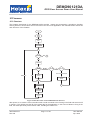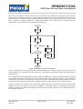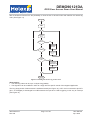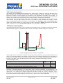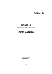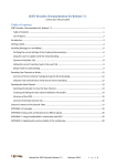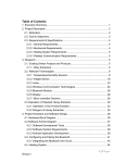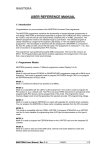
1
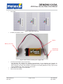
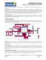
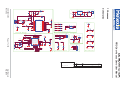
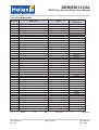
DEMO90121DA RFID Door Access Demo User Manual Features and Benefits Applications Short range contacless Door Access Control Short range RFID terminal Battery operated stand alone RFID reader 10$ BOM cost target Low power consumption (400uA average) Optimized form factor for easy integration Ordering Information Part No. DEMO90121DA Description RFID Door Access Demonstrator 1 Scope The DEMO90121DA is a turnkey contactless door access example based on the RFID transceiver IC MLX90121. Once set up, it detects and reads ISO14443A cards and is capable through software configuration of lighting a red or a green LED. As a stand alone application running on battery, the current consumption is optimized, taking into account a fast response time. The form factor is minimized to demonstrate the high level of integration allowed by the MLX90121. The bill of material of DEMO90121DA targets a cost of 10$ per component set for 1000 modules. This document includes fast start instructions, describes the performance of the demo and explains its hardware and software. One can see this document as a starting point for building their own access control system by adapting the functions and performances to their specific requirements. 2 Related Melexis Products MLX90121 – 13.56MHz transceiver Complete schematics, bill of material and layout are annexed to this document allowing a fast start for development. Source code of the firmware is based on the FW90121 library and is available on the CD ROM provided with the DEMO90121DA. This device is based on ISO14443A RFID standard, but the software library makes it is easy to adapt the firmware to use another ISO protocol. Note 1: The device is for demonstration purpose and has not been tested for compliance with FCC, ETSI or any other regulations. Note 2: The MLX90121 is limited to positive temperatures in the ISO14443A mode. Therefore and without any changes, this demonstrator is suitable for indoor applications. Should you require outdoor operations, you may modify its firmware to use the demonstrator with ISO14443B cards. 390129012103 Rev 002 Page 1 of 20 User Manual Apr. 2008 DEMO90121DA RFID Door Access Demo User Manual Table of Contents 1 Scope ...................................................................................................................................................... 1 2 Related Melexis Products ................................................................................................................... 1 3 Introduction ........................................................................................................................................... 3 4 Box Content........................................................................................................................................... 3 5 Connections .......................................................................................................................................... 5 6 Working principle ................................................................................................................................. 5 7 Functions and use................................................................................................................................ 5 7.1 System initialization .......................................................................................................................... 5 7.2 Opening the door............................................................................................................................... 5 7.3 Transfer access right ........................................................................................................................ 5 8 Observations ......................................................................................................................................... 6 9 Hardware ................................................................................................................................................ 7 9.1 General............................................................................................................................................... 7 9.2 RF part ............................................................................................................................................... 7 9.3 Microcontroller .................................................................................................................................. 8 9.4 Power................................................................................................................................................. 9 9.5 Clock.................................................................................................................................................. 9 9.6 Interface........................................................................................................................................... 10 10 Firmware ............................................................................................................................................ 11 10.1 Structure ........................................................................................................................................ 11 10.2 Practical information..................................................................................................................... 15 11 Power consumption......................................................................................................................... 15 12 Conclusion......................................................................................................................................... 16 13 Annexes.............................................................................................................................................. 17 14 Disclaimer .......................................................................................................................................... 20 390129012103 Rev 002 Page 2 of 20 User Manual Apr. 2008 DEMO90121DA RFID Door Access Demo User Manual 3 Introduction You purchased a DEMO90121DA. Thanks for choosing Melexis. This demonstrator is a contactless door access solution based on the MLX90121. This document contains the instructions to use and evaluate the functions and the performances of this demonstrator. All the necessary hardware is provided in the packaging box and the microcontroller on-board is already programmed with the same firmware as the one present on the CD. All that you need to do is to plug the cables, and then to check visually the LED status when one or more of the tag cards are close to the antenna. Should you want to start a development based on this demonstrator, you will find in this document and on the CD all information like schematics, board layout, list of component, firmware source (C code) and the related application note. Please note that all this material is provided to support the use of the related Melexis product. Duplication, circulation or storage on data carriers in any manner for any other type of use are not authorized by Melexis unless specific agreement. 4 Box Content You will find in the box the following components. • 1 RFID reader board LED D3 Battery cable connector Antenna connector LED D4 Figure 1 RFID reader board. Top side • 1 antenna board Antenna connector Figure 2 Antenna ANT2_0 390129012103 Rev 002 Page 3 of 20 User Manual Apr. 2008 DEMO90121DA RFID Door Access Demo User Manual • 3 tag cards Figure 3 ISO14443A tag cards • 9V battery and battery cable Battery Battery connector Connector to reader board Figure 4 The 9V battery and the power supply cable • • • 1 CD with the firmware and documentation The delivered CD contains the complete documentation of the hardware and firmware for DEMO90121DA, User Manual, Datasheet MLX90121, Source Code of the firmware (written in C, flavor AVR gcc), Hex file of the firmware, Schematics of the board (ORCAD 9.2 file), Layout of the board (GERBER files), Bill of materials of the board 1 User Manual (on paper) - this document 1 Box Content (on paper) 390129012103 Rev 002 Page 4 of 20 User Manual Apr. 2008 DEMO90121DA RFID Door Access Demo User Manual 5 Connections The first step is to connect the component. Connect antenna board to the RFID reader board (3 pin connector). Then, connect battery cable to the RFID reader board (2 pin connector). Plug the battery to the battery connector of the cable. 6 Working principle Once connected, this demonstrator allows the use of several functions which are generally used in RFID door access devices. Its principle is based on the unique identification number (UID) of ISO14443A tags. The demonstrator is able to store several UID. All cards which UID number is stored in the device can open the door. Each card is associated with a specific access privilege, Master Key or Valid Key. The highest card level (Master Key) which is unique (It can be only one card with Mater key privilege) can transfer its rights to open the door to a card which acquire by this way the second access level (Valid Key). The device can be re-initialized. By this way, one can change the card with the Master Key privilege and remove all other card from the Valid Key card list. When powering on the module or resetting it through its reset button, the module starts an initialisation phase: • If no tag is present in the reading range of the antenna, nothing changes in the configuration. The UIDs previously stored in the memory are kept. • If one tag is present, the device will read its UID, store it and associate it with the Master Key privilege and delete other UID from memory. • If two or more tags are present, nothing changes in the configuration. The UIDs previously stored in the memory are kept. As this device could be an example for battery powered access control system, the power consumption was optimized. Therefore, the device is running in low power mode the main part of the time and switch on its tag detection function for few instant. In absence of tag, the device enters back in low power. In the opposite case, it starts an RFID communication and the door access function. 7 Functions and use 7.1 System initialization Place a card on the antenna. Press BUTTON1 (reset) of the DEMO90121DA and check that the LEDs D3 and afterwards D2 start to blink rapidly (microcontroller registers tag card nr.1 as master card) 7.2 Opening the door The device executes this operation in 3 steps; tag detection, opening ISO14443A communication, reading and checking the UID. Approach any kind of card near to the antenna. LEDs D2 and D3 will be on together indicating that a tag is detected. If this card is compliant to ISO14443A, then D2 will blink alone once. In the opposite case, nothing more happens. If this card has any access privilege (Master or Valid Key) then D3 will blink alone once, meaning that the card is recognized as valid card. In other case, nothing more happens. 7.3 Transfer access right Put the card with the Master Key privilege (card A) together with another card (card B) close to the antenna. LEDs D2 and D3 will be on together (tag detected), then D2 alone will blink two times (two ISO14443A cards are detected), then D3 alone will blink two times (two valid codes are stored in microcontroller memory). This means that right to open the door is transferred from the card A to the card B. The card B UID is added as Valid Key card one. 390129012103 Rev 002 Page 5 of 20 User Manual Apr. 2008 DEMO90121DA RFID Door Access Demo User Manual 8 Observations 1. Reading range of the DEMO90121DA is about 10cm. 2. Tag detection is made by change of the antenna field load compared to previous cycle (one cycle is about 300ms or longer). Therefore, the LEDs D2 and D3 blinking once together indicating in this way the field change. It could occur that approaching objects to the antenna generates a tag detection indication 3. When one or more ISO14443 tag cards are already in the field, just after the tag detection indication D2 will blink indicating how many cards it detected: once if only one card, twice if it detected two cards, etc. 4. In order to reduce a too strong coupling between tag cards, fan them a little when approaching two or more to the antenna. 5. The valid tag codes are stored in the non-volatile memory of the microcontroller of the DEMO90121DA, so after a power-off the codes are not lost. 6. The average current consumption is ~0.4mA (no change of the antenna load). 390129012103 Rev 002 Page 6 of 20 User Manual Apr. 2008 DEMO90121DA RFID Door Access Demo User Manual 9 Hardware 9.1 General The DEMO90121DA is built around the MLX90121 RFID transceiver front-end and the 8bit microcontroller Atmel ATMega8. The MLX90121 handles the air interface in transmission and in reception. It drives the antenna through its Class E power driver in order to generate the HF magnetic field and modulation according to the protocol and command generated by the microcontroller. It demodulates the answer from the tag and provides digital signals to the microcontroller. The ATMega8 runs the protocol and the application software. The board has three interfaces, one for the door opening mecanism, a SPI connection for the uC programmation, and a debug connector. It embeds a reset button, clock and power management functions and can be powered from a battery. 9.2 RF part Emission The MLX90121 integrates a class E driver capable of, providing up to 200mW to the antenna. The Class E driver (TX pin) is connected to the antenna through a resonant load and an adapter circuit. In order to give users the choice to connect to a variety of different antennas, the transceiver output is matched to 50ȍ impedance. The adaptation impedance is composed by L2, C6 (resonant load), CV2 , C8, L4, L3, C10, CV1 (impedance adaptor). In order to get the best performance, it is necessary to tune the adaptation circuit. The tuning operation starts by adjusting CV2 to get the maximum amplitude. Once CV2 is fixed, the adjustment of CV1 can be done. Any 13.56MHz antenna matched to 50ȍ can be used. However, care should be taken for its quality factor, which has to be between 10 and 25. In case antennas with other than 50ȍ impedance the capacitor C9 is used to match the output. Tuning of the antenna has to be done when placed in it’s final position because close proximity to metallic parts, including wires can cause changes from its characteristics in free-air. For some tips in building the antenna see 13.56MHz RFID systems and antennas design guide. L1 BLM31AJ601SN1 C6 C7 + 5V C1 L2 47pF 100nF 4.7uF/Tantal 1.2uH GND _TX R1 1 CV2 2 2K2 2.8-12.5pF 5V C8 L4 U2 MLX90121 BLM31AJ601SN 1 L3 L5 C ON2 680nH 3 2 1 6.8uH 1 15pF C9 xxpF C V1 5.5-50pF C10 150pF(130pF) 2 R2 1 Antenna 2 10E GND_TX 5 C12 6 220pF 2 1 4 GND _TX CLK13M TP1 3 7 R3 100k Gnd 1 Close to Antenna connector 8 GND_uC 9 GND_TX RTB GND_TX 10 VDD1 TX MOD RX VSS3 NC VSS1 VDD3 XOUT DSY NC XIN VSS2 XBU F CK MODE DIN NC VDD2 RTB DOUT 20 19 18 R SSI GND_RX 17 16 D SYNC 15 CK 14 MODE 13 D IN C11 100nF GND_RX 12 11 5V D OUT C13 100nF Close to pin 7 of MLX90121 TAG Reader MLX90121 GND_uC Figure 5 . MLX90121 transceiver block. 390129012103 Rev 002 Page 7 of 20 User Manual Apr. 2008 DEMO90121DA RFID Door Access Demo User Manual Reception The reception is done through the R1 resistor which connects the receiver part of the MLX90121 to the antenna. It’s value can vary from 1kȍ up to 4.7kȍ depending in the back modulation amplitude and the reading distance. In this example 2.2kȍ gives the best compromise. Special care must be taken when using other values. If R1 is too big the DC bias voltage and the back modulation signal seen by the receiver are not enough for correct reception. If R1 is too small the DC bias voltage saturates the receiver input. Modulation depth The 10ȍ resistor R2 fixes the 10% modulation index for the ISO14443B communication. When using ISO14443A cards, the R1 resistor is bypassed by the internal modulation transistor. In case of OOK is used, resistor can be kept here or not mounted. 9.3 Microcontroller Connection to MLX90121 The microcontroller controls the MLX90121, manages the clock signals and interfaces the RFID function to the application, i.e the door lock mechanism. Port D is used to connect the MLX90121 through the signals CK, DSYNC, DOUT, DIN, RTB and MODE. DOUT DSYNC RST Y1 2 C 16 100nF 13.56MHZ C19 C 20 22pF GND_uC 22pF 2 RSSI C 17 10nF C 18 100nF 1 R11 100k RSSI_f il C15 10nF GND _ADC GND_ADC GN D_AD C GND_AD C GN D_uC GND_uC 1 R15 10M 24 23 22 21 20 19 18 17 DIN RTB MODE SCK MISO MOSI uC (ADC, memory, serial interface) TP3 1 1 R 12 100 PD 3 PC1 PD 4 PC0 GND ADC7 $7 PHJD GND VC C GND ATmega8-16AU AREF VC C ADC6 PB6 AVC C PB7 PB5 BLM31AJ601SN 1 1 2 3 4 5 6 7 8 CK 2 GND_uC L6 PD 5 PD 6 PD 7 PB0 PB1 PB2 PB3 PB4 5V 22nF CLK13M PD2 PD1 PD0 PC6 PC5 PC4 PC3 PC2 U3 9 10 11 12 13 14 15 16 C21 32 31 30 29 28 27 26 25 1 10M 5V Limiter2 Limiter1 R16 2 Gnd Good_Card Bad_C ard LockMotor GND_ADC Figure 6. Microcontroller block. Clock A 13.56MHz quartz crystal oscillator is connected between PB6 and PB7 for the generation of the clock. The resistor R12 is used to attenuate the fast transients generated by the clock connection between MLX90121 and ATMega8. Wakeup Cycles In order to reduce the power consumption, the microcontroller alternates sleep and wakeup modes. This cycle is generated by means of a RC circuit composed of R16 and C21 connected on PD3. The time constant given by the RC enables an interrupt (INT) after about 280ms. The precision is given by the tolerances of R16 and C21. Programming and development The microcontroller can be programmed onboard using the SPI interface. This serial interface associated with adequate hardware and software allows read and write access to all memory blocks of the microcontroller. This is useful for firmware updates or changes in case of adaptation to specific requirement. 390129012103 Rev 002 Page 8 of 20 User Manual Apr. 2008 DEMO90121DA RFID Door Access Demo User Manual Code size The firmware used in the DEMO90121DA requires 5.2KBytes of program FLASH of the ATMega8. The microcontroller ATMega8 can be substituted by other pin-compatible ATMEL models, with different characteristics and prices. 9.4 Power The DEMO90121DA embeds a 5V regulator and therefore requires at minimum a 6V DC voltage supply. A diode is used after the power connector to protect the board against reverse voltage. U1 D1 XC62FP5002P (SOT-89) C3 C2 10uF/Tantal 100nF OUT IN 2 GND 3 1 5V 2 30BQ060 C4 100nF C5 10uF/Tantal CON1 1 2 1 Supply Edge of the board Soldered on a free PCB area of at least 1cm2 (filled with vias) Supply Figure 7 Voltage regulator 5V The MLX90121 has three sets of supply pins (power and ground) corresponding to its three main blocks: the digital block, the transmitter block and the receiver block. It is important to separate carefully the supply lines to reduce the noise issues. Therefore, supply pins are connected as follows: - the digital block supply pins VSS2 and VDD2 respectively to the microcontroller digital ground and directly to the main +5V; - the transmiter supply pins to the TX ground plane (VSS1) and the VDD1 insulated from the main +5V by a filtering circuit (L1, C7 and C1); - the receiver supply pins to the RX ground plane (VSS3) and VDD3 to the main +5V through another filter (L5, C11). The reference clock block of the MLX90121 is internally connected to the transmiter block, so the components at pins XIN, XOUT should be placed on the same ground plane (GND_TX). The microcontroller has two different sets of supply pins, the digital supply (GND_uC and the main +5V) and the analog one for the ADC, (GDN_ADC and AVCC pin) supplied from the main 5V through a filter (L6, C18). The microcontroller is awake about 0.98% of the time, and the transmitter 0.25% of the time. The measured average supply current is below 0.41mA. The two layer PCB has several ground planes that are connected one to each other by shunts that can be substituted by some small value resistors (0805 case) in order to reduce noise propagation between the different functional blocks: 9.5 Clock The unique clock source reference is one quartz resonator of 13.56MHz connected to the microcontroller. In order to reduce the component count and the bill of material, the Xtal is shared and the clock output PB7 from the microcontroller is fed to the clock input XIN of the transceiver. 390129012103 Rev 002 Page 9 of 20 User Manual Apr. 2008 DEMO90121DA RFID Door Access Demo User Manual 9.6 Interface There are additional components that interface the microcontroller to the ’external world’: An SPI interface which can be used for microcontroller programming, a reset switch for initialization of the system, a debug connector for the developer to verify the firmware changes and the functional interface composed of 2 LEDs , 2 digital level inputs for two position sensors (Limiter1 and Limiter2) and one low power digital level output (LockMotor). R4 2 1 CH_RST 1K R5 2 1 CH_MOSI MOSI J1 CH_MOSI 5V 1K R6 2 1 CH_MISO MISO 2 CH _RST CH _SCK CH _MISO 2 4 6 Downloader 100 R7 SCK 1 3 5 female R ST GND _uC 1 CH_SCK 1K Serial Interface for uC Limiter2 1K R10 1 2 2 R9 8K2 DoorMechanism Edge of the board 3 1 BUTTON1 D2 BAS16 1 Limiter1 1 4 3 2 1 R8 2 5V CON3 LockMotor RST 1 3 1K C14 100nF GND _uC 11 R 14 11 R13 GN D_uC uC reset circuit 1K 2 Bad_Card 1K 2 Good_Card Button_Reset Edge of the board J2 D3 D4 GND_uC LED R 2 2 LED G GN D_uC CK MODE DIN DOUT RTB DSY NC 1 2 3 4 5 6 7 TP_90121dig GND_uC Door Mechanism Signals debug connector Figure 8 Microcontroller interface to 'external' world Developers should add an adequate power buffer to be able to drive the door-lock motor or electromagnet. 390129012103 Rev 002 Page 10 of 20 User Manual Apr. 2008 DEMO90121DA RFID Door Access Demo User Manual 10 Firmware 10.1 Structure The firmware developed for the DEMO90121DA provides master tag programming, anticollision handling and tag detection as the basic service functions of the door lock application. The flowchart below shows the main structure of the firmware: Figure 9 Main flowchart of the DEMO90121DA firmware After power-on or reset the microcontroller sends a read command to the first tag in the field and stores its ID in memory. This will become the ID of the master tag for the application. In the event of absence of tag in the field, the codes previously stored remain valid, including the master one. 390129012103 Rev 002 Page 11 of 20 User Manual Apr. 2008 DEMO90121DA RFID Door Access Demo User Manual Once done, the firmware enters in its main loop. The RSSI level is measured and compared to the reference stored in the microcontroller memory in order to detect the presence of a tag in the field. Without any tag, the system will enter into sleep mode for the period defined by the RC circuit connected on PD3. If a tag is in the field, it starts an inventory according to ISO14443A protocol (see Figure 10) and reads all the IDs (identification codes) answering to its requests. (See Figure 9) Figure 10 Reading the tag codes in the field If only one valid tag is in the field the microcontroller sends the command to open the door. If there are several valid tags in the field but not the master tag , they will be ignored and the door will not be opened. (See Figure 9) If the master tag is detected together with other tags (ISO14443A), the firmware registers all codes as valid, and will reset all previous valid ones. In order to prevent valid codes redefinition by error, this registering is conditioned by the state of the two limiters: door-lock should be opened and door handle pushed. If only the master tag is in the field, the list stays as-is, and the command to open the door is sent. (See Figure 9) In order to reduce the success rate of code-scan hacking devices, the door-lock can be opened in the presence of only one valid tag in the field. This applies to the master tag too. A closed door limit switch condition restricts the firmware to access the function to open the door, and for only one valid tag present in the field. (See Figure 9) 390129012103 Rev 002 Page 12 of 20 User Manual Apr. 2008 DEMO90121DA RFID Door Access Demo User Manual After a hardware reset there is the possibility to clean the list of all valid codes and redefine the master tag code. (See Figure 11) Figure 11 Reading the master tag code at reset Observations: The valid tag codes can be up to 12 bytes long (96bits). The algorithm can be modified in order to comply with the specific needs of the targeted application. The long sleep period of about 300ms is hardware based (see Figure 12): a RC circuit connected to pin INT1 (pin 1 of ATMega8) is discharged from VDD towards the input level ‘LOW’ triggering in this way an interrupt (see Figure 12). 390129012103 Rev 002 Page 13 of 20 User Manual Apr. 2008 DEMO90121DA RFID Door Access Demo User Manual In order to reduce the power consumption of the device, we use POWER DOWN mode of the microcontroller. All clocks are stopped and only the watch-dog is running. The watch-dog is reset at the end of the main loop, and also after long delays. Figure 12 Sleep 300ms sequence 390129012103 Rev 002 Page 14 of 20 User Manual Apr. 2008 DEMO90121DA RFID Door Access Demo User Manual 10.2 Practical information The firmware of the DEMO90121DA is based on the FW121 library. (FW90121: Firmware description) This library provides the ISO15693 and ISO14443 protocol functions as specific commands to control the MLX90121, address its internal registers, and read/write to the EEPROM of the ATMEL microcontroller. At power-on or reset, the microcontroller IO ports, timers, ADC, and watch-dog, and the MLX90121 transceiver registers are configured for the ISO14443A protocol as described in the MLX90121 datasheet. The firmware was developed using GCC under AVR Studio 4. The firmware can be loaded in the microcontroller using the SPI interface connected to a STK500, STK300, AVRISP mkII module or similar, driven by appropriate software (AVR Studio, PonyProg2000, etc). FW_DA21_14A.c and FW_DA21_14A.h contain the firmware specific gcc code and the functions’ prototypes. HwDefs.h describes the hardware (input, output pins, etc.). The file FW_DA21_14A.aps is the AVR Studio 4 project file. 11 Power consumption The DEMO90121DA is built for running on battery power and the current consumption is therefore optimized. The picture below (Figure 13) shows the typical current consumption variation during one cycle (loop). Figure 13 Supply current variation (No tag in field) The average current consumption is about 0.41mA giving 100 days autonomy using a 1000mAh battery. This value is of course dependant on the number of access events and is deeply impacted by the consumption of the door lock mecanism. Special care should be taken for the choice of RSSI threshold (dVrssi parameter). If its value is too small, noise can make the device start inventory attempts without tags in proximity. &XUUHQWFRQVXPSWLRQYDOXHV Working phase: parameters Current Period [mA] [ms] both microcontroller and MLX90121 in power-down: I1 and t1 0.16 288 microcontroller active and MLX90121 in power-down: I2 and t2 4.6 1.64 wake-up phase of MLX90121 (idle mode) and microcontroller activ: I3 and t3 18.5 0.49 MLX90121 in transmit mode and microcontroller active: I4 and t4 75 0.74 As shown in the table, MLX90121 is in power-down most of the time (t1§288ms). The transmitter is on for very short time if the RSSI signal didn’t change since last loop, then the microcontroller puts MLX90121 in power-down. If the RSSI signal changed significantly MLX90121 sends the inventory commands, and is afterwards put in power-down mode (t4 increases to tens of ms). The microcontroller will continue to check the inventory results and eventually open the door-lock, or store the new codes in EEPROM. 390129012103 Rev 002 Page 15 of 20 User Manual Apr. 2008 DEMO90121DA RFID Door Access Demo User Manual Using four alkaline AA batteries to supply the application board DEMO90121DA with 10 actuations (ISO14443A tag cards passed through the 13.56MHz field) per day, the voltage variation looks like depicted in Figure 14. VBat in time 0:00:00 0 24:00:00 48:00:00 72:00:00 96:00:00 120:00:00 144:00: 00 -0.01 -0.02 dV -0.03 -0.04 -0.05 -0.06 hh:mm:ss Figure 14 Battery voltage variation during a few days 12 Conclusion The DEMO90121DA is an example of a small, cost effective, and simple control module for door access based on the Melexis 13.56MHz transceiver MLX90121. It can also be considered as an advanced starting point for developers who want to build their own system meeting their specific requirements. The software library FW121 facilitates the software development for MLX90121 transceiver, and the programmer can use high level commands to communicate with the MLX90121. By this way, they can concentrate on the management of the microcontroller and the upper level functionality of the application. References source files: FW_DA21_14A.h, FW_DA21_14A.c, FW_DA21_14A.aps, HwDefs.h. schematics: See below Layout: See below MLX90121 datasheet ATMega8 datasheet FW90121: Firmware description 13.56MHz RFID systems and antennas design guide 390129012103 Rev 002 Page 16 of 20 User Manual Apr. 2008 U1 3 O UT 4.7uF /Tant al C3 1.2uH C2 10uF /Tant al G ND_TX 100nF CO N1 2 1 2 1 30BQ060 C4 100nF 1 100nF 2 IN C1 L2 47pF D1 XC 62F P5002P (SO T- 89) 5V GND + C7 5V C5 Supply Edge of the board 10uF /Tantal R1 1 Soldered on a free PCB area of at least 1cm2 (filled with vias) 2 CV2 2K2 Supply 2. 8- 12.5pF MLX90121 L5 CON 2 680nH 3 2 1 6.8uH 1 15pF C9 xxpF CV1 5. 5- 50pF C 10 150pF (130pF) 2 R2 Antenna 1 2 3 4 10E GND_TX GND_TX 5 C 12 6 2 1 CLK13M TP1 220pF 7 R3 100k Gnd 8 G ND_uC 1 Close to Antenna connector 9 GN D_TX RTB 10 GND _TX RX VD D1 VSS3 TX MOD NC VSS1 VDD 3 XOUT DSYNC CK XIN MODE VSS2 DIN XBUF NC VDD 2 RTB DOU T 20 19 RSSI 18 G ND_RX 17 R4 RST 2 TP2 1 CH_RST Close to CON1 Gnd 16 DSYNC 15 CK 14 MOD E C11 100nF MOSI 1K R5 2 1 CH_MO SI MISO 1K R6 2 1 CH_MI SO SCK 100 R7 2 1 CH_SCK GN D_R X DIN 13 12 5V 11 DOU T C13 J1 CH_MO SI 5V 1 3 5 female U2 1 5V C8 L4 BLM31AJ601SN1 L3 13 Annexes C6 Schematics 390129012103 Rev 002 L1 BLM31AJ601SN1 CH_RST CH_SCK CH_MI SO 2 4 6 Downloader SHUN T1 2 1 GN D_uC 1ohm 100nF 1K GN D_TX C20 22pF GND _uC 22pF D IN R TB MODE uC (ADC, memory, serial interface) D2 BAS16 GND_TX Butt on_Reset Edge of the board 2 SHUN T2 2 1 1ohm R13 Gnd Good_Card Bad_Card LockMotor 1K 2 Same D3 horizontal or vertical line GN D_uC Close to pin 5 of ATmega8 GND_uC LED R CK MOD E DIN DOU T RTB DSYNC G ND_uC Door Mechanism Signals SHUN T4 2 1 J2 D4 LED G GND_uC GND_ADC GND_uC uC reset circuit R14 GND_ADC TP3 GND _uC Bad_Card 11 C15 10nF 1K 2 C18 100nF GN D_RX Close to Capa Var 1 2 C14 100nF G ood_C ar d SCK MISO MOSI 1ohm BUTTON1 RST R11 100k RSSI_f il C 17 10nF SHUN T3 2 1 R9 8K2 1K R SSI GND _ADC GND_AD C G ND_ADC GND_uC GN D_uC 1 13.56MHZ C19 24 23 22 21 20 19 18 17 Door Mechanism Edge of the board 2 2 C16 100nF R15 10M PC1 PC0 ADC7 GND AREF ADC6 AVCC PB5 11 Y1 PD3 PD4 GND VCC $ 7PHJD GND ATmega8- 16AU VCC PB6 PB7 2 1 R12 100 1K R10 1 2 Limit er 2 1 CK 2 GN D_uC PD2 PD1 PD0 PC6 PC5 PC4 PC3 PC2 1 2 3 4 5 6 7 8 22nF C LK13M 2 1 2 3 4 5 6 7 1ohm GND_uC debug connector CAGE Code GND connections DWG N O R ev A3 1.1 MELEXI S Technologies SA Thur sday, August 09, 2007 Scale RF 90121DA: 13.56MHz Tag Reader f or door access applicat ions Sheet 1 of 1 User Manual Apr. 2008 DEMO90121DA Size GN D_ADC Close to pin 5 of ATmega8 TP_90121dig RFID Door Access Demo User Manual Page 17 of 20 5V 1 1 L6 U3 PD5 PD6 PD7 PB0 PB1 PB2 PB3 PB4 C21 9 10 11 12 13 14 15 16 10M 4 3 2 1 R8 Limit er 1 BLM31AJ601SN1 1 32 31 30 29 28 27 26 25 2 5V CON3 LockMotor 5V Limiter2 Limiter1 3 R ST R 16 2 D OUT D SYN C 1 TAG Reader MLX90121 Close to pin 4 of MLX90121 Serial Interface for uC GND_uC 1 Close to pin 7 of MLX90121 DEMO90121DA RFID Door Access Demo User Manual List of components 1 1 1 1 2 1 2 8 BUTTON1 CON1 CON2 CON3 CV1, CV2 C1 C2, C5 C3,C4,C7,C11,C13,C14,C16,C18 Button_Reset Supply Antenna DoorMechanism 5.5-50pF 4.7uF/Tantal 10uF/Tantal 100nF Type of component button connector connector connector variable capacitor tantalum capacitor tantalum capacitor capacitor 1 1 1 1 1 1 1 2 1 1 1 1 1 1 1 3 1 1 1 1 1 2 4 2 1 3 1 1 4 3 1 1 1 1 C6 C8 C9* C10 C12 C15 C17 C20,C19 C21 D1 D2 D3 D4 J1 J2* L1,L5,L6 L2 L3 L4 R1 R2 R3,R11 R4,R5,R7,R8 R12,R6 R9 R10,R13,R14 R15 R16 SHUNT1,SHUNT2,SHUNT3,SHUNT4 TP1,TP2,TP3 U1 U2 U3 Y1 47pF 15pF 0pF** 150pF(130pF) 220pF 1nF 10nF 22pF 22nF 30BQ060 BAS16 LED G 1,8MM LED R 1,8MM Downloader TP_90121dig BLM31AJ601SN1 1.2uH 680nH 6.8uH 4K7** 10** 100K 1K 100 8K2 1K 10M 10M 0ohm** Gnd XC62FP5002P (Torex) MLX90121 (Melexis) ATmega8-16AU (Atmel) 13.56MHZ capacitor capacitor capacitor capacitor capacitor capacitor capacitor capacitor capacitor Schottky diode low-power diode LED LED connector connector EMI filter inductor inductor inductor resistor resistor resistor resistor resistor resistor resistor resistor resistor resistor test point voltage regulator 13MHz transceiver uC quartz resonator Quantity Reference * Optional component. ** Value 390129012103 Rev 002 to Part be Page 18 of 20 adjusted if necessary User Manual Apr. 2008 DEMO90121DA RFID Door Access Demo User Manual Layout TOP BOTTOM 390129012103 Rev 002 Page 19 of 20 User Manual Apr. 2008 DEMO90121DA RFID Door Access Demo User Manual 14 Disclaimer Devices sold by Melexis are covered by the warranty and patent indemnification provisions appearing in its Term of Sale. Melexis makes no warranty, express, statutory, implied, or by description regarding the information set forth herein or regarding the freedom of the described devices from patent infringement. Melexis reserves the right to change specifications and prices at any time and without notice. Therefore, prior to designing this product into a system, it is necessary to check with Melexis for current information. This product is intended for use in normal commercial applications. Applications requiring extended temperature range, unusual environmental requirements, or high reliability applications, such as military, medical lifesupport or life-sustaining equipment are specifically not recommended without additional processing by Melexis for each application. The information furnished by Melexis is believed to be correct and accurate. However, Melexis shall not be liable to recipient or any third party for any damages, including but not limited to personal injury, property damage, loss of profits, loss of use, interrupt of business or indirect, special incidental or consequential damages, of any kind, in connection with or arising out of the furnishing, performance or use of the technical data herein. No obligation or liability to recipient or any third party shall arise or flow out of Melexis’ rendering of technical or other services. © 2007 Melexis NV. All rights reserved. For the latest version of this document, go to our website at www.melexis.com Or for additional information contact Melexis Direct: America: Europe, Africa, Asia: Asia: phone: +1 603 223 2362 E-mail: [email protected] Phone: +32 1367 0495 E-mail: [email protected] Phone: +32 1367 0495 E-mail: [email protected] ISO/TS 16949 and ISO14001 Certified 390129012103 Rev 002 Page 20 of 20 User Manual Apr. 2008