1
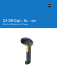
DS4308/DS4308P
DIGITAL SCANNER
PRODUCT REFERENCE GUIDE
DS4308/DS4308P DIGITAL SCANNER
PRODUCT REFERENCE GUIDE
MN000327A01
Revision A
August 2014
ii
DS4308/DS4308P Digital Scanner Product Reference Guide
No part of this publication may be reproduced or used in any form, or by any electrical or mechanical means, without permission in writing.
This includes electronic or mechanical means, such as photocopying, recording, or information storage and retrieval systems. The material
in this manual is subject to change without notice.
The software is provided strictly on an “as is” basis. All software, including firmware, furnished to the user is on a licensed basis. We grant
to the user a non-transferable and non-exclusive license to use each software or firmware program delivered hereunder (licensed
program). Except as noted below, such license may not be assigned, sublicensed, or otherwise transferred by the user without our prior
written consent. No right to copy a licensed program in whole or in part is granted, except as permitted under copyright law. The user shall
not modify, merge, or incorporate any form or portion of a licensed program with other program material, create a derivative work from a
licensed program, or use a licensed program in a network without written permission. The user agrees to maintain our copyright notice on
the licensed programs delivered hereunder, and to include the same on any authorized copies it makes, in whole or in part. The user
agrees not to decompile, disassemble, decode, or reverse engineer any licensed program delivered to the user or any portion thereof.
We reserve the right to make changes to any software or product to improve reliability, function, or design.
We do not assume any product liability arising out of, or in connection with, the application or use of any product, circuit, or application
described herein.
No license is granted, either expressly or by implication, estoppel, or otherwise under any of our intellectual property rights. An implied
license only exists for equipment, circuits, and subsystems contained in our products.
This media, or Symbol Technologies Product, may include Symbol Technologies Software, Commercial Third Party Software, and Publicly
Available Software.
The Symbol Technologies Software that may be included on this media, or included in the Symbol Technologies Product, is Copyright (c)
by Symbol Technologies, Inc., and its use is subject to the licenses, terms and conditions of the agreement in force between the purchaser
of the Symbol Technologies Product and Symbol Technologies, Inc.
The Commercial Third Party Software that may be included on this media, or included in the Symbol Technologies Product, is subject to
the licenses, terms and conditions of the agreement in force between the purchaser of the Symbol Technologies Product and Symbol
Technologies, Inc., unless a separate Commercial Third Party Software License is included, in which case, your use of the Commercial
Third Party Software will then be governed by the separate Commercial Third Party License.
The Publicly Available Software that may be included on this media, or in the Symbol Technologies Product, is listed below. The use of the
listed Publicly Available Software is subject to the licenses, terms and conditions of the agreement in force between the purchaser of the
Symbol Technologies Product and Symbol Technologies, Inc., as well as, the terms and conditions of the license of each Publicly Available
Software package. Copies of the licenses for the listed Publicly Available Software, as well as, all attributions, acknowledgements, and
software information details, are included below. Symbol Technologies is required to reproduce the software licenses, acknowledgments
and copyright notices as provided by the Authors and Owners, thus, all such information is provided in its native language form, without
modification or translation.
The Publicly Available Software in the list below is limited to the Publicly Available Software included by Symbol Technologies. The
Publicly Available Software included by Commercial Third Party Software or Products, that is used in the Symbol Technologies Product,
are disclosed in the Commercial Third Party Licenses, or via the respective Commercial Third Party Publicly Available Software Legal
Notices.
Publicly available software list:
Name:
Regular Expression Evaluator
Version:
8.3
Software Site:
http://www.freebsd.org/cgi/cvsweb.cgi/src/lib/libc/regex
Modified:
No
Source Code:
The Source Code for this Software Package may be obtained from the Software Site identified above.
License:
BSD 4-Clause License ("Original BSD")
© 1992 Henry Spencer.
© 1992, 1993 The Regents of the University of California. All rights reserved.
This code is derived from software contributed to Berkeley by Henry Spencer of the University of Toronto. Redistribution and use in source
and binary forms, with or without modification, are permitted provided that the following conditions are met:
1. Redistributions of source code must retain the above copyright notice, this list of conditions and the following disclaimer.
2. Redistributions in binary form must reproduce the above copyright notice, this list of conditions and the following disclaimer in the
documentation and/or other materials provided with the distribution.
3. All advertising materials mentioning features or use of this software must display the following acknowledgement:
This product includes software developed by the University of California, Berkeley and its contributors.
4. Neither the name of the University nor the names of its contributors may be used to endorse or promote products derived from this
software without specific prior written permission.
iii
THIS SOFTWARE IS PROVIDED BY THE REGENTS AND CONTRIBUTORS ``AS IS'' AND ANY EXPRESS OR IMPLIED
WARRANTIES, INCLUDING, BUT NOT LIMITED TO, THE IMPLIED WARRANTIES OF MERCHANTABILITY AND FITNESS FOR A
PARTICULAR PURPOSE ARE DISCLAIMED. IN NO EVENT SHALL THE REGENTS OR CONTRIBUTORS BE LIABLE FOR ANY
DIRECT, INDIRECT, INCIDENTAL, SPECIAL, EXEMPLARY, OR CONSEQUENTIAL DAMAGES (INCLUDING, BUT NOT LIMITED TO,
PROCUREMENT OF SUBSTITUTE GOODS OR SERVICES; LOSS OF USE, DATA, OR PROFITS; OR BUSINESS INTERRUPTION)
HOWEVER CAUSED AND ON ANY THEORY OF LIABILITY, WHETHER IN CONTRACT, STRICT LIABILITY, OR TORT (INCLUDING
NEGLIGENCE OR OTHERWISE) ARISING IN ANY WAY OUT OF THE USE OF THIS SOFTWARE, EVEN IF ADVISED OF THE
POSSIBILITY OF SUCH DAMAGE.
Warranty
For the complete hardware product warranty statement, go to: http://www.motorolasolutions.com/warranty.
iv
DS4308/DS4308P Digital Scanner Product Reference Guide
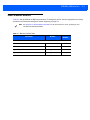
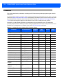
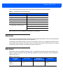
Revision History
Changes to the original guide are listed below:
Change
-01 Rev A
Date
8/2014
Description
Initial release
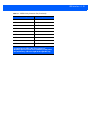
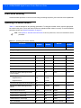
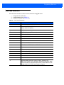
TABLE OF CONTENTS
About This Guide
Introduction .....................................................................................................................................
Configurations.................................................................................................................................
Chapter Descriptions ......................................................................................................................
Notational Conventions...................................................................................................................
Related Documents ........................................................................................................................
Service Information .........................................................................................................................
xvii
xvii
xviii
xix
xx
xx
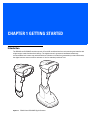
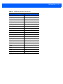
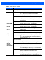
Chapter 1: Getting Started
Introduction ....................................................................................................................................
Interfaces .......................................................................................................................................
Unpacking ......................................................................................................................................
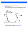
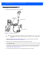
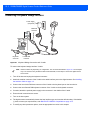
Setting Up the Digital Scanner .......................................................................................................
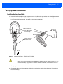
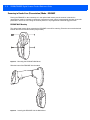
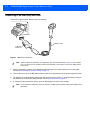
Installing the Interface Cable ...................................................................................................
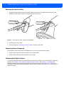
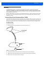
Removing the Interface Cable .................................................................................................
Connecting Power (if required) ................................................................................................
Configuring the Digital Scanner ...............................................................................................
Accessories ....................................................................................................................................
1-1
1-2
1-2
1-3
1-3
1-4
1-4
1-4
1-5
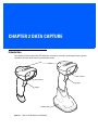
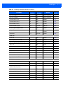
Chapter 2: Data Capture
Introduction ....................................................................................................................................
Beeper Definitions ..........................................................................................................................
LED Definitions ..............................................................................................................................
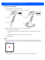
Scanning ........................................................................................................................................
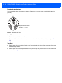
Scanning in Hands-Free (Presentation) Mode - DS4308 ........................................................
Scanning in Hands-Free (Presentation) Mode - DS4308P ......................................................
Scanning in Hand-Held Mode ..................................................................................................
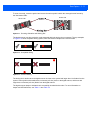
Aiming ......................................................................................................................................
Decode Ranges .............................................................................................................................
2-1
2-2
2-4
2-5
2-5
2-8
2-10
2-10
2-12
vi
DS4308/DS4308P Digital Scanner Product Reference Guide
Chapter 3: Maintenance & Technical Specifications
Introduction ....................................................................................................................................
Maintenance ..................................................................................................................................
General Scanner Maintenance ................................................................................................
Healthcare Scanner Maintenance ............................................................................................
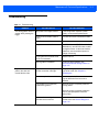
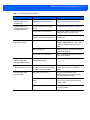
Troubleshooting .............................................................................................................................
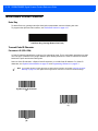
Report Software Version Bar Code ..........................................................................................
Technical Specifications ................................................................................................................
Digital Scanner Signal Descriptions ...............................................................................................
3-1
3-1
3-1
3-1
3-3
3-6
3-7
3-9
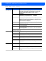
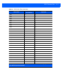
Chapter 4: User Preferences & Miscellaneous Options
Introduction ....................................................................................................................................
Scanning Sequence Examples ......................................................................................................
Errors While Scanning ...................................................................................................................
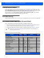
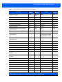
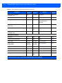
User Preferences/Miscellaneous Options Parameter Defaults ......................................................
User Preferences ...........................................................................................................................
Default Parameters ..................................................................................................................
Parameter Bar Code Scanning ................................................................................................
Beep After Good Decode .........................................................................................................
Direct Decode Indicator ...........................................................................................................
Beeper Volume ........................................................................................................................
Beeper Tone ............................................................................................................................
Beeper Duration .......................................................................................................................
Suppress Power Up Beeps ......................................................................................................
Decode Pager Motor ................................................................................................................
Decode Pager Motor Duration .................................................................................................
Night Mode ...............................................................................................................................
Low Power Mode .....................................................................................................................
Hand-Held Trigger Mode .........................................................................................................
Hands-Free Mode ....................................................................................................................
Hands-Free/Hand-Held Auto Switching (DS4308P Only) ........................................................
Hand-Held Decode Aiming Pattern ..........................................................................................
Hands-Free Decode Aiming Pattern ........................................................................................
Hands-Free Motionless Timeout (DS4308P Only) ...................................................................
Motion Detect Range (DS4308P Only) ....................................................................................
Picklist Mode ............................................................................................................................
Continuous Bar Code Read .....................................................................................................
Unique Bar Code Reporting .....................................................................................................
Decode Session Timeout .........................................................................................................
Timeout Between Decodes, Same Symbol .............................................................................
Timeout Between Decodes, Different Symbols .......................................................................
Fuzzy 1D Processing ...............................................................................................................
Decode Mirror Images (Data Matrix Only) ...............................................................................
Mobile Phone/Display Mode ....................................................................................................
PDF Prioritization .....................................................................................................................
PDF Prioritization Timeout .......................................................................................................
Presentation Mode Field of View .............................................................................................
Decoding Illumination ...............................................................................................................
Post Decode Illumination (DS4308P Only) ..............................................................................
Illumination Brightness .............................................................................................................
4-1
4-2
4-2
4-2
4-5
4-5
4-6
4-7
4-8
4-9
4-10
4-11
4-11
4-12
4-12
4-14
4-16
4-19
4-20
4-20
4-21
4-22
4-22
4-23
4-24
4-25
4-25
4-26
4-26
4-27
4-27
4-28
4-29
4-30
4-30
4-31
4-31
4-32
4-32
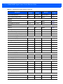
Table of Contents
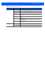
Low Light Scene Detection ......................................................................................................
Motion Tolerance (Hand-Held Trigger Modes Only) ................................................................
Movement Sensitivity (DS4308P Only) ....................................................................................
Object Detection Method (DS4308P Only) ..............................................................................
Miscellaneous Scanner Parameters ..............................................................................................
Enter Key .................................................................................................................................
Transmit Code ID Character ....................................................................................................
Prefix/Suffix Values ..................................................................................................................
Scan Data Transmission Format .............................................................................................
FN1 Substitution Values ..........................................................................................................
Transmit “No Read” Message ..................................................................................................
Unsolicited Heartbeat Interval ..................................................................................................
4-33
4-34
4-34
4-35
4-36
4-36
4-36
4-37
4-38
4-39
4-40
4-41
Chapter 5: Imaging Preferences
Introduction ....................................................................................................................................
Scanning Sequence Examples ......................................................................................................
Errors While Scanning ...................................................................................................................
Imaging Preferences Parameter Defaults ......................................................................................
Imaging Preferences ......................................................................................................................
Operational Modes ...................................................................................................................
Image Capture Illumination ......................................................................................................
Image Capture Autoexposure ..................................................................................................
Fixed Exposure ........................................................................................................................
Fixed Gain ................................................................................................................................
Gain/Exposure Priority for Snapshot Mode ..............................................................................
Snapshot Mode Timeout ..........................................................................................................
Snapshot Aiming Pattern .........................................................................................................
Silence Operational Mode Changes ........................................................................................
Image Cropping .......................................................................................................................
Crop to Pixel Addresses ..........................................................................................................
Image Size (Number of Pixels) ................................................................................................
Image Brightness (Target White) .............................................................................................
JPEG Image Options ...............................................................................................................
JPEG Target File Size .............................................................................................................
JPEG Quality and Size Value ..................................................................................................
Image Enhancement ................................................................................................................
Image File Format Selector ......................................................................................................
Image Rotation .........................................................................................................................
Bits Per Pixel ............................................................................................................................
Signature Capture ....................................................................................................................
Signature Capture File Format Selector ..................................................................................
Signature Capture Bits Per Pixel .............................................................................................
Signature Capture Width ..........................................................................................................
Signature Capture Height ........................................................................................................
Signature Capture JPEG Quality .............................................................................................
Video Mode Format Selector ...................................................................................................
Video View Finder ....................................................................................................................
Target Video Frame Size .........................................................................................................
Video View Finder Image Size .................................................................................................
5-1
5-2
5-2
5-2
5-4
5-4
5-5
5-5
5-6
5-6
5-7
5-8
5-9
5-9
5-10
5-11
5-12
5-13
5-13
5-14
5-14
5-15
5-16
5-17
5-18
5-19
5-20
5-21
5-22
5-22
5-22
5-23
5-23
5-24
5-24
vii
viii
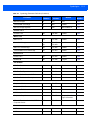
DS4308/DS4308P Digital Scanner Product Reference Guide
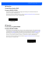
Chapter 6: USB Interface
Introduction ....................................................................................................................................
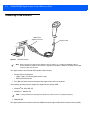
Connecting a USB Interface ..........................................................................................................
USB Parameter Defaults ...............................................................................................................
USB Host Parameters ...................................................................................................................
USB Device Type .....................................................................................................................
Symbol Native API (SNAPI) Status Handshaking ....................................................................
USB Keystroke Delay ..............................................................................................................
USB CAPS Lock Override .......................................................................................................
USB Ignore Unknown Characters ............................................................................................
USB Convert Unknown to Code 39 .........................................................................................
Emulate Keypad .......................................................................................................................
Emulate Keypad with Leading Zero .........................................................................................
Quick Keypad Emulation ..........................................................................................................
USB Keyboard FN 1 Substitution .............................................................................................
Function Key Mapping .............................................................................................................
Simulated Caps Lock ...............................................................................................................
Convert Case ...........................................................................................................................
USB Static CDC .......................................................................................................................
Optional USB Parameters .............................................................................................................
Ignore Beep Directive ..............................................................................................................
Ignore Bar Code Configuration Directive .................................................................................
USB Polling Interval .................................................................................................................
USB Fast HID ..........................................................................................................................
IBM Specification Version ........................................................................................................
ASCII Character Set for USB .........................................................................................................
6-1
6-2
6-3
6-5
6-5
6-7
6-7
6-8
6-8
6-9
6-9
6-10
6-10
6-11
6-11
6-12
6-12
6-13
6-14
6-14
6-14
6-15
6-16
6-17
6-18
Chapter 7: SSI Interface
Introduction ....................................................................................................................................
Communications ............................................................................................................................
SSI Transactions ...........................................................................................................................
General Data Transactions ......................................................................................................
Transfer of Decode Data ..........................................................................................................
Communication Summary .............................................................................................................
RTS/CTS Lines ........................................................................................................................
ACK/NAK Option ......................................................................................................................
Number of Data Bits .................................................................................................................
Serial Response Time-out .......................................................................................................
Retries ......................................................................................................................................
Baud Rate, Stop Bits, Parity, Response Time-out, ACK/NAK Handshake ..............................
Errors .......................................................................................................................................
Things to Remember When Using SSI Communication ................................................................
Using Time Delay to Low Power Mode with SSI ...........................................................................
Encapsulation of RSM Commands/Responses over SSI ..............................................................
Command Structure .................................................................................................................
Response Structure .................................................................................................................
Example Transaction ...............................................................................................................
Simple Serial Interface Default Parameters ...................................................................................
SSI Host Parameters .....................................................................................................................
Select SSI Host ........................................................................................................................
7-1
7-1
7-3
7-3
7-4
7-5
7-5
7-5
7-5
7-5
7-5
7-6
7-6
7-6
7-7
7-8
7-8
7-8
7-9
7-10
7-11
7-11
Table of Contents
Baud Rate ................................................................................................................................
Parity ........................................................................................................................................
Check Parity .............................................................................................................................
Stop Bits ...................................................................................................................................
Software Handshaking .............................................................................................................
Host RTS Line State ................................................................................................................
Decode Data Packet Format ....................................................................................................
Host Serial Response Time-out ...............................................................................................
Host Character Time-out ..........................................................................................................
Multipacket Option ...................................................................................................................
Interpacket Delay .....................................................................................................................
Event Reporting .............................................................................................................................
Decode Event ..........................................................................................................................
Boot Up Event ..........................................................................................................................
Parameter Event ......................................................................................................................
7-12
7-13
7-14
7-14
7-15
7-16
7-16
7-17
7-18
7-19
7-20
7-21
7-21
7-22
7-22
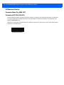
Chapter 8: RS-232 Interface
Introduction ....................................................................................................................................
Connecting an RS-232 Interface ....................................................................................................
RS-232 Parameter Defaults ...........................................................................................................
RS-232 Host Parameters ...............................................................................................................
RS-232 Host Types ..................................................................................................................
Baud Rate ................................................................................................................................
Parity ........................................................................................................................................
Stop Bit Select .........................................................................................................................
Data Bits ..................................................................................................................................
Check Receive Errors ..............................................................................................................
Hardware Handshaking ...........................................................................................................
Software Handshaking .............................................................................................................
Host Serial Response Time-out ...............................................................................................
RTS Line State .........................................................................................................................
Beep on <BEL> ........................................................................................................................
Intercharacter Delay .................................................................................................................
Nixdorf Beep/LED Options .......................................................................................................
Ignore Unknown Characters ....................................................................................................
ASCII Character Set for RS-232 ....................................................................................................
8-1
8-2
8-3
8-4
8-6
8-8
8-9
8-10
8-10
8-11
8-11
8-13
8-15
8-16
8-16
8-17
8-18
8-18
8-19
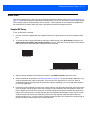
Chapter 9: IBM 468X / 469X Interface
Introduction ....................................................................................................................................
Connecting to an IBM 468X/469X Host .........................................................................................
IBM Parameter Defaults .................................................................................................................
IBM 468X/469X Host Parameters ..................................................................................................
Port Address ............................................................................................................................
Convert Unknown to Code 39 ..................................................................................................
Ignore Beep Directive ..............................................................................................................
Ignore Bar Code Configuration Directive .................................................................................
9-1
9-2
9-3
9-4
9-4
9-5
9-5
9-6
ix
x
DS4308/DS4308P Digital Scanner Product Reference Guide
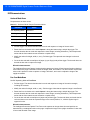
Chapter 10: Keyboard Wedge Interface
Introduction ....................................................................................................................................
Connecting a Keyboard Wedge Interface ......................................................................................
Keyboard Wedge Parameter Defaults ...........................................................................................
Keyboard Wedge Host Parameters ...............................................................................................
Keyboard Wedge Host Types ..................................................................................................
Ignore Unknown Characters ....................................................................................................
Keystroke Delay .......................................................................................................................
Intra-Keystroke Delay ..............................................................................................................
Alternate Numeric Keypad Emulation ......................................................................................
Quick Keypad Emulation ..........................................................................................................
Simulated Caps Lock ...............................................................................................................
Caps Lock Override .................................................................................................................
Convert Wedge Case ...............................................................................................................
Function Key Mapping .............................................................................................................
FN1 Substitution ......................................................................................................................
Send Make and Break .............................................................................................................
Keyboard Maps ........................................................................................................................
ASCII Character Set for Keyboard Wedge ....................................................................................
10-1
10-2
10-3
10-4
10-4
10-4
10-5
10-5
10-6
10-6
10-7
10-7
10-8
10-8
10-9
10-9
10-10
10-11
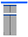
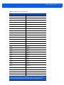
Chapter 11: Symbologies
Introduction ....................................................................................................................................
Scanning Sequence Examples ......................................................................................................
Errors While Scanning ...................................................................................................................
Symbology Parameter Defaults .....................................................................................................
Enable/Disable All Code Types .....................................................................................................
UPC/EAN .......................................................................................................................................
Enable/Disable UPC-A .............................................................................................................
Enable/Disable UPC-E .............................................................................................................
Enable/Disable UPC-E1 ...........................................................................................................
Enable/Disable EAN-8/JAN-8 ..................................................................................................
Enable/Disable EAN-13/JAN-13 ..............................................................................................
Enable/Disable Bookland EAN ................................................................................................
Decode UPC/EAN/JAN Supplementals ...................................................................................
User-Programmable Supplementals ........................................................................................
UPC/EAN/JAN Supplemental Redundancy .............................................................................
UPC/EAN/JAN Supplemental AIM ID Format ..........................................................................
UPC Reduced Quiet Zone .......................................................................................................
Transmit UPC-A Check Digit ...................................................................................................
Transmit UPC-E Check Digit ...................................................................................................
Transmit UPC-E1 Check Digit .................................................................................................
UPC-A Preamble .....................................................................................................................
UPC-E Preamble .....................................................................................................................
UPC-E1 Preamble ...................................................................................................................
Convert UPC-E to UPC-A ........................................................................................................
Convert UPC-E1 to UPC-A ......................................................................................................
EAN-8/JAN-8 Extend ...............................................................................................................
Bookland ISBN Format ............................................................................................................
UCC Coupon Extended Code ..................................................................................................
Coupon Report .........................................................................................................................
11-1
11-1
11-2
11-2
11-8
11-9
11-9
11-9
11-10
11-10
11-11
11-11
11-12
11-15
11-15
11-16
11-17
11-17
11-18
11-18
11-19
11-20
11-21
11-22
11-22
11-23
11-23
11-24
11-24
Table of Contents
ISSN EAN ................................................................................................................................
Code 128 .......................................................................................................................................
Enable/Disable Code 128 ........................................................................................................
Set Lengths for Code 128 ........................................................................................................
Enable/Disable GS1-128 (formerly UCC/EAN-128) .................................................................
Enable/Disable ISBT 128 .........................................................................................................
ISBT Concatenation .................................................................................................................
Check ISBT Table ....................................................................................................................
ISBT Concatenation Redundancy ............................................................................................
Code 128 Security Level ..........................................................................................................
Code 128 Reduced Quiet Zone ...............................................................................................
Ignore Code 128 <FNC4> ........................................................................................................
Code 39 .........................................................................................................................................
Enable/Disable Code 39 ..........................................................................................................
Enable/Disable Trioptic Code 39 .............................................................................................
Convert Code 39 to Code 32 ...................................................................................................
Code 32 Prefix .........................................................................................................................
Set Lengths for Code 39 ..........................................................................................................
Code 39 Check Digit Verification .............................................................................................
Transmit Code 39 Check Digit .................................................................................................
Code 39 Full ASCII Conversion ...............................................................................................
Code 39 Security Level ............................................................................................................
Code 39 Reduced Quiet Zone .................................................................................................
Code 93 .........................................................................................................................................
Enable/Disable Code 93 ..........................................................................................................
Set Lengths for Code 93 ..........................................................................................................
Code 11 .........................................................................................................................................
Code 11 ...................................................................................................................................
Set Lengths for Code 11 ..........................................................................................................
Code 11 Check Digit Verification .............................................................................................
Transmit Code 11 Check Digits ...............................................................................................
Interleaved 2 of 5 (ITF) ..................................................................................................................
Enable/Disable Interleaved 2 of 5 ............................................................................................
Set Lengths for Interleaved 2 of 5 ............................................................................................
I 2 of 5 Check Digit Verification ................................................................................................
Transmit I 2 of 5 Check Digit ....................................................................................................
Convert I 2 of 5 to EAN-13 .......................................................................................................
I 2 of 5 Security Level ..............................................................................................................
I 2 of 5 Reduced Quiet Zone ....................................................................................................
Discrete 2 of 5 (DTF) .....................................................................................................................
Enable/Disable Discrete 2 of 5 .................................................................................................
Set Lengths for Discrete 2 of 5 ................................................................................................
Codabar (NW - 7) ...........................................................................................................................
Enable/Disable Codabar ..........................................................................................................
Set Lengths for Codabar ..........................................................................................................
CLSI Editing .............................................................................................................................
NOTIS Editing ..........................................................................................................................
Codabar Upper or Lower Case Start/Stop Characters Detection ............................................
MSI .................................................................................................................................................
Enable/Disable MSI .................................................................................................................
Set Lengths for MSI .................................................................................................................
xi
11-25
11-26
11-26
11-26
11-28
11-28
11-29
11-30
11-30
11-31
11-32
11-32
11-33
11-33
11-33
11-34
11-34
11-35
11-36
11-36
11-37
11-38
11-39
11-40
11-40
11-40
11-42
11-42
11-42
11-44
11-45
11-46
11-46
11-46
11-48
11-49
11-49
11-50
11-51
11-52
11-52
11-52
11-54
11-54
11-54
11-56
11-56
11-57
11-58
11-58
11-58
xii
DS4308/DS4308P Digital Scanner Product Reference Guide
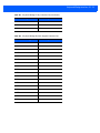
MSI Check Digits .....................................................................................................................
Transmit MSI Check Digit(s) ....................................................................................................
MSI Check Digit Algorithm .......................................................................................................
Chinese 2 of 5 ................................................................................................................................
Enable/Disable Chinese 2 of 5 .................................................................................................
Matrix 2 of 5 ...................................................................................................................................
Enable/Disable Matrix 2 of 5 ....................................................................................................
Set Lengths for Matrix 2 of 5 ....................................................................................................
Matrix 2 of 5 Check Digit ..........................................................................................................
Transmit Matrix 2 of 5 Check Digit ...........................................................................................
Korean 3 of 5 .................................................................................................................................
Enable/Disable Korean 3 of 5 ..................................................................................................
Inverse 1D .....................................................................................................................................
GS1 DataBar .................................................................................................................................
GS1 DataBar-14 ......................................................................................................................
GS1 DataBar Limited ...............................................................................................................
GS1 DataBar Expanded ..........................................................................................................
Convert GS1 DataBar to UPC/EAN .........................................................................................
GS1 DataBar Limited Security Level .......................................................................................
Composite ......................................................................................................................................
Composite CC-C ......................................................................................................................
Composite CC-A/B ...................................................................................................................
Composite TLC-39 ...................................................................................................................
UPC Composite Mode .............................................................................................................
Composite Beep Mode ............................................................................................................
GS1-128 Emulation Mode for UCC/EAN Composite Codes ....................................................
Postal Codes .................................................................................................................................
US Postnet ...............................................................................................................................
US Planet .................................................................................................................................
Transmit US Postal Check Digit ...............................................................................................
UK Postal .................................................................................................................................
Transmit UK Postal Check Digit ...............................................................................................
Japan Postal ............................................................................................................................
Australia Post ...........................................................................................................................
Australia Post Format ..............................................................................................................
Netherlands KIX Code ............................................................................................................
USPS 4CB/One Code/Intelligent Mail ......................................................................................
UPU FICS Postal .....................................................................................................................
2D Symbologies .............................................................................................................................
Enable/Disable PDF417 ...........................................................................................................
Enable/Disable MicroPDF417 ..................................................................................................
Code 128 Emulation ................................................................................................................
Data Matrix ...............................................................................................................................
Data Matrix Inverse ..................................................................................................................
Maxicode ..................................................................................................................................
QR Code ..................................................................................................................................
QR Inverse ...............................................................................................................................
MicroQR ...................................................................................................................................
Aztec ........................................................................................................................................
Aztec Inverse ...........................................................................................................................
Han Xin ....................................................................................................................................
11-60
11-60
11-61
11-62
11-62
11-63
11-63
11-63
11-65
11-65
11-66
11-66
11-67
11-68
11-68
11-68
11-69
11-69
11-70
11-71
11-71
11-71
11-72
11-72
11-73
11-73
11-74
11-74
11-74
11-75
11-75
11-76
11-76
11-77
11-78
11-79
11-79
11-80
11-81
11-81
11-81
11-82
11-83
11-83
11-84
11-84
11-85
11-85
11-86
11-86
11-87
Table of Contents
xiii
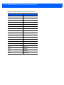
Han Xin Inverse .......................................................................................................................
Symbology-Specific Security Levels ..............................................................................................
Redundancy Level ...................................................................................................................
Security Level ..........................................................................................................................
1D Quiet Zone Level ................................................................................................................
Intercharacter Gap Size ...........................................................................................................
Report Version ...............................................................................................................................
Macro PDF Features ......................................................................................................................
Flush Macro Buffer ...................................................................................................................
Abort Macro PDF Entry ............................................................................................................
11-87
11-88
11-88
11-90
11-91
11-92
11-92
11-93
11-93
11-93
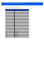
Chapter 12: Intelligent Document Capture
Introduction ....................................................................................................................................
The IDC Process ............................................................................................................................
Bar Code Acceptance Test ......................................................................................................
Capture Region Determination ................................................................................................
Image Post Processing ............................................................................................................
Data Transmission ...................................................................................................................
PC Application and Programming Support ....................................................................................
Parameters ....................................................................................................................................
IDC Operating Mode ................................................................................................................
IDC Symbology ........................................................................................................................
IDC X Coordinate .....................................................................................................................
IDC Y Coordinate .....................................................................................................................
IDC Width .................................................................................................................................
IDC Height ...............................................................................................................................
IDC Aspect ...............................................................................................................................
IDC File Format Selector .........................................................................................................
IDC Bits Per Pixel ....................................................................................................................
IDC JPEG Quality ....................................................................................................................
IDC Find Box Outline ...............................................................................................................
IDC Minimum Text Length .......................................................................................................
IDC Maximum Text Length ......................................................................................................
IDC Captured Image Brighten ..................................................................................................
IDC Captured Image Sharpen .................................................................................................
IDC Border Type ......................................................................................................................
IDC Delay Time ........................................................................................................................
IDC Zoom Limit ........................................................................................................................
IDC Maximum Rotation ............................................................................................................
Quick Start .....................................................................................................................................
Sample IDC Setup ...................................................................................................................
IDC Demonstrations .................................................................................................................
Other Suggestions ...................................................................................................................
Quick Start Form ......................................................................................................................
12-1
12-1
12-2
12-2
12-3
12-3
12-3
12-4
12-5
12-6
12-7
12-7
12-8
12-8
12-9
12-9
12-10
12-10
12-11
12-11
12-12
12-12
12-13
12-14
12-15
12-15
12-16
12-17
12-17
12-18
12-19
12-19
xiv
DS4308/DS4308P Digital Scanner Product Reference Guide
Chapter 13: OCR Programming
Introduction ....................................................................................................................................
OCR Parameter Defaults ...............................................................................................................
OCR Programming Parameters .....................................................................................................
Enable/Disable OCR-A ............................................................................................................
OCR-A Variant .........................................................................................................................
Enable/Disable OCR-B ............................................................................................................
OCR-B Variant .........................................................................................................................
Enable/Disable MICR E13B .....................................................................................................
Enable/Disable US Currency Serial Number ...........................................................................
OCR Orientation ......................................................................................................................
OCR Lines ...............................................................................................................................
OCR Minimum Characters .......................................................................................................
OCR Maximum Characters ......................................................................................................
OCR Subset .............................................................................................................................
OCR Quiet Zone ......................................................................................................................
OCR Template .........................................................................................................................
OCR Check Digit Modulus .......................................................................................................
OCR Check Digit Multiplier ......................................................................................................
OCR Check Digit Validation .....................................................................................................
Inverse OCR ............................................................................................................................
13-1
13-2
13-3
13-3
13-3
13-5
13-6
13-9
13-10
13-10
13-12
13-12
13-13
13-13
13-14
13-15
13-24
13-25
13-26
13-31
Chapter 14: Driver’s License Set Up (DS4308-DL)
Introduction ....................................................................................................................................
Driver’s License Parsing ................................................................................................................
Parsing Driver’s License Data Fields (Embedded Driver's License Parsing) ................................
Embedded Driver's License Parsing Criteria - Code Type ......................................................
Driver’s License Parse Field Bar Codes ..................................................................................
AAMVA Parse Field Bar Codes ...............................................................................................
User Preferences ...........................................................................................................................
Set Default Parameter .............................................................................................................
Output Gender as M or F .........................................................................................................
Date Format .............................................................................................................................
Send Keystroke (Control Characters and Keyboard Characters) ............................................
Parsing Rule Example ...................................................................................................................
Embedded Driver's License Parsing ADF Example .................................................................
14-1
14-2
14-3
14-3
14-4
14-7
14-17
14-17
14-17
14-18
14-20
14-39
14-43
Chapter 15: 123Scan2
Introduction ....................................................................................................................................
Communication with 123Scan2 .....................................................................................................
123Scan2 Requirements ...............................................................................................................
Scanner SDK, Other Software Tools, and Videos .........................................................................
15-1
15-1
15-2
15-2
Chapter 16: Advanced Data Formatting
Introduction .................................................................................................................................... 16-1
Table of Contents
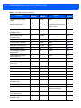
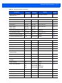
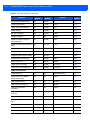
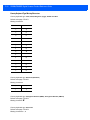
Appendix A: Standard Default Parameters
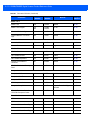
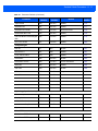
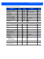
Appendix B: Country Codes
Introduction .................................................................................................................................... B-1
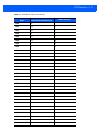
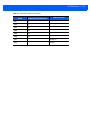
USB and Keyboard Wedge Country Keyboard Types (Country Codes) ........................................ B-2
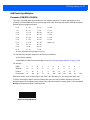
Appendix C: Country Code Pages
Introduction .................................................................................................................................... C-1
Country Code Page Defaults ......................................................................................................... C-1
Country Code Page Bar Codes ..................................................................................................... C-5
Appendix D: CJK Decode Control
Introduction ....................................................................................................................................
CJK Control Parameters ................................................................................................................
Unicode Output Control ...........................................................................................................
CJK Output Method to Windows Host .....................................................................................
Non-CJK UTF Bar Code Output ..............................................................................................
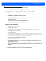
Unicode/CJK Decode Setup with Windows Host ...........................................................................
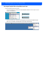
Setting Up the Windows Registry Table for Unicode Universal Output ...................................
Adding CJK IME on Windows ..................................................................................................
Selecting the Simplified Chinese Input Method on the Host ....................................................
Selecting the Traditional Chinese Input Method on the Host ...................................................
D-1
D-2
D-2
D-3
D-5
D-7
D-7
D-7
D-8
D-9
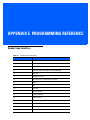
Appendix E: Programming Reference
Symbol Code Identifiers ................................................................................................................. E-1
AIM Code Identifiers ...................................................................................................................... E-3
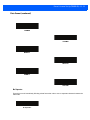
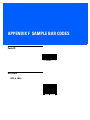
Appendix F: Sample Bar Codes
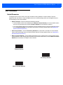
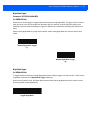
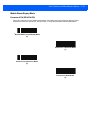
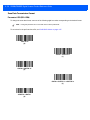
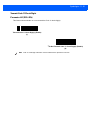
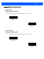
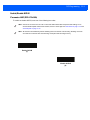
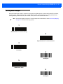
Code 39 .........................................................................................................................................
UPC/EAN .......................................................................................................................................
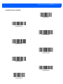
UPC-A, 100% ...........................................................................................................................
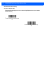
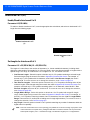
EAN-13, 100% .........................................................................................................................
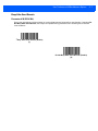
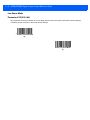
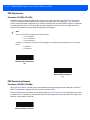
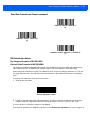
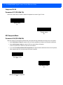
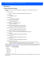
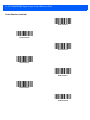
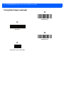
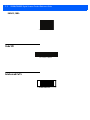
Code 128 .......................................................................................................................................
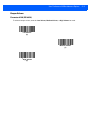
Interleaved 2 of 5 ...........................................................................................................................
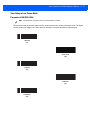
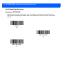
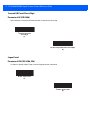
GS1 DataBar-14 ............................................................................................................................
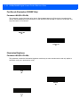
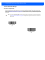
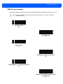
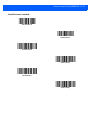
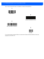
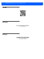
PDF417 ..........................................................................................................................................
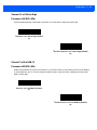
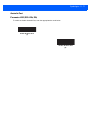
Data Matrix .....................................................................................................................................
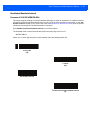
Maxicode ........................................................................................................................................
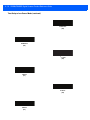
QR Code ........................................................................................................................................
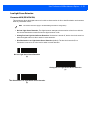
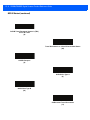
US Postnet .....................................................................................................................................
UK Postal .......................................................................................................................................
F-1
F-1
F-1
F-2
F-2
F-2
F-3
F-3
F-3
F-3
F-4
F-4
F-4
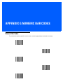
Appendix G: Numeric Bar Codes
Numeric Bar Codes ........................................................................................................................ G-1
Cancel ............................................................................................................................................ G-2
xv
xvi
DS4308/DS4308P Digital Scanner Product Reference Guide
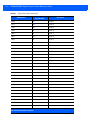
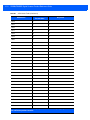
Appendix H: ASCII Character Sets
Appendix I: Signature Capture Code
Introduction ....................................................................................................................................
Code Structure ...............................................................................................................................
Signature Capture Area ...........................................................................................................
CapCode Pattern Structure ......................................................................................................
Start / Stop Patterns ......................................................................................................................
Dimensions ....................................................................................................................................
Data Format ...................................................................................................................................
Additional Capabilities ...................................................................................................................
Signature Boxes ............................................................................................................................
Index
I-1
I-1
I-1
I-2
I-2
I-3
I-3
I-4
I-4
ABOUT THIS GUIDE
Introduction
The DS4308/DS4308P Product Reference Guide provides general instructions for setting up, operating,
maintaining, and troubleshooting the DS4308 series digital scanner.
Configurations
This guide includes the following DS4308 series digital scanner configurations:
• DS4308-SR00006ZZWW
DS4308 Area Imager, Standard Range, Corded, Nova White
• DS4308-SR00007ZZWW
DS4308 Area Imager, Standard Range, Corded, Twilight Black
• DS4308-DL00006ZZWW
DS4308 Area Imager, Driver’s License (DL) Parsing, Corded, Nova White
• DS4308-DL00007ZZWW
DS4308 Area Imager, DL Parsing, Corded, Twilight Black
• DS4308-HD00007ZZWW
DS4308 Area Imager, High Density, Corded, Twilight Black
• DS4308-HL00007ZZWW
DS4308 Area Imager, High Density, DL Parsing, Corded, Twilight Black
• DS4308-HC0000BZZWW
DS4308 Area Imager, Healthcare, Corded, HC White
• DS4308-HD00007ZCWW
DS4308 Area Imager, High Density, Corded, Checkpoint EAS, Twilight Black
• DS4308-HL00007ZCWW
DS4308 Area Imager, High Density, DL Parsing, Corded, Checkpoint EAS,
Twilight Black
• DS4308P-SR00007PZWW
DS4308 Area Imager with Integrated Presentation Stand, Standard Range,
Corded, Twilight Black
• DS4308P-DL00007PZWW
DS4308 Area Imager with Integrated Presentation Stand, DL Parsing,
Corded, Twilight Black
• DS4308P-SR00007PCWW
DS4308 Area Imager with Integrated Presentation Stand, Standard Range,
Corded, Checkpoint EAS, Twilight Black
• DS4308P-DL00007PCWW
DS4308 Area Imager with Integrated Presentation Stand, DL Parsing,
Corded, Checkpoint EAS, Twilight Black
xviii
DS4308/DS4308P Digital Scanner Product Reference Guide
Chapter Descriptions
Topics covered in this guide are as follows:
• Chapter 1, Getting Started provides a product overview, unpacking instructions, and cable connection
information.
• Chapter 2, Data Capture provides beeper and LED definitions, techniques involved in scanning bar
codes, general instructions and tips about scanning, and decode ranges.
• Chapter 3, Maintenance & Technical Specifications provides suggested digital scanner maintenance,
troubleshooting, technical specifications, and signal descriptions (pinouts).
• Chapter 4, User Preferences & Miscellaneous Options describes each user preference feature and
provides programming bar codes for selecting these features.
• Chapter 5, Imaging Preferences describes imaging preference features and provides programming bar
codes for selecting these features.
• Chapter 6, USB Interface describes how to set up the digital scanner with a USB host.
• Chapter 7, SSI Interface describes the system requirements of the Simple Serial Interface (SSI), which
provides a communications link between Symbol Technologies decoders and a serial host.
• Chapter 8, RS-232 Interface describes how to set up the digital scanner with an RS-232 host.
• Chapter 9, IBM 468X / 469X Interface describes how to set up the digital scanner with an IBM
468X/469X host.
• Chapter 10, Keyboard Wedge Interface describes how to set up a keyboard wedge interface with the
digital scanner.
• Chapter 11, Symbologies describes all symbology features and provides programming bar codes for
selecting these features for the digital scanner.
• Chapter 12, Intelligent Document Capture describes IDC, an advanced image processing firmware,
including IDC functionality, parameter bar codes to control its features, and a quick start procedure.
• Chapter 13, OCR Programming describes how to set up the digital scanner for OCR programming.
• Chapter 14, Driver’s License Set Up (DS4308-DL) describes how to program the DS4308-DL digital
scanner to read and use the data contained in the 2D bar codes on US driver's licenses and AAMVA
compliant ID cards.
• Chapter 15, 123Scan2 provides information on the PC-based digital scanner configuration tool
123Scan2.
• Chapter 16, Advanced Data Formatting briefly describes ADF, a means of customizing data before
transmission to the host device, and includes a reference to the ADF Programmer Guide.
• Appendix A, Standard Default Parameters provides a table of all host devices and miscellaneous
scanner defaults.
• Appendix B, Country Codes provides bar codes for programming the country keyboard type for the USB
keyboard (HID) device and the keyboard wedge host.
• Appendix C, Country Code Pages provides bar codes for selecting code pages for the country keyboard
type.
• Appendix D, CJK Decode Control describes control parameters for Unicode/CJK (Chinese, Japanese,
Korean) bar code decode through USB HID Keyboard Emulation mode.
About This Guide
• Appendix E, Programming Reference provides a table of AIM code identifiers, ASCII character
conversions, and keyboard maps.
• Appendix F, Sample Bar Codes includes sample bar codes of various code types.
• Appendix G, Numeric Bar Codes includes the numeric bar codes to scan for parameters requiring
specific numeric values.
• Appendix H, ASCII Character Sets provides ASCII character value tables.
• Appendix I, Signature Capture Code describes CapCode, a special pattern that encloses a signature
area on a document and allows the scanner to capture a signature.
Notational Conventions
The following conventions are used in this document:
• Unless stated otherwise, DS4308 refers to both the DS4308 and DS4308P configurations
• Italics are used to highlight the following:
• Chapters and sections in this and related documents
• Dialog box, window and screen names
• Drop-down list and list box names
• Check box and radio button names
• Bold text is used to highlight the following:
• Key names on a keypad
• Button names on a screen.
• bullets (•) indicate:
• Action items
• Lists of alternatives
• Lists of required steps that are not necessarily sequential
• Sequential lists (e.g., those that describe step-by-step procedures) appear as numbered lists.
• Throughout the programming bar code menus, asterisks (*) are used to denote default parameter
settings.
* Indicates Default
*Baud Rate 9600
Feature/Option
xix
xx
DS4308/DS4308P Digital Scanner Product Reference Guide
Related Documents
• DS4308 Series Quick Start Guide, p/n MN000328A01 - provides general information for getting started
with the DS4308 digital scanner, and includes basic set up and operation instructions.
• DS4308P Series Quick Start Guide, p/n MN000883A01 - provides general information for getting started
with the DS4308P pedestal scanner, and includes basic set up and operation instructions.
• Advanced Data Formatting Programmer Guide, p/n 72E-69680-xx - provides information on ADF, a
means of customizing data before transmission to a host.
For the latest version of this guide and all guides, go to: http://www.motorolasolutions.com/support.
Service Information
If you have a problem using the equipment, contact your facility's technical or systems support. If there is a
problem with the equipment, they will contact the Customer Support Center at:
http://www.motorolasolutions.com/support.
When contacting support, please have the following information available:
• Serial number of the unit
• Model number or product name
• Software type and version number
Symbol Technologies responds to calls by e-mail, telephone or fax within the time limits set forth in service
agreements.
If your problem cannot be solved by support, you may need to return your equipment for servicing and will be
given specific directions. Symbol Technologies is not responsible for any damages incurred during shipment if
the approved shipping container is not used. Shipping the units improperly can possibly void the warranty.
If you purchased your business product from a Symbol Technologies business partner, please contact that
business partner for support.
CHAPTER 1 GETTING STARTED
Introduction
The DS4308 and DS4308P combine superior 1D and 2D omnidirectional bar code scanning and transfer with
a light-weight, hands-free/hand-held design. The digital scanner’s gooseneck Intellistand seamlessly
accommodates both counter-top and hand-held use. Whether in hands-free (presentation) or hand-held mode,
the digital scanner ensures comfort and ease of use for extended periods of time.
Figure 1-1 DS4308 and DS4308P Digital Scanner
1-2
DS4308/DS4308P Digital Scanner Product Reference Guide
Interfaces
The DS4308 digital scanner supports:
• USB connection to a host. The digital scanner autodetects a USB host and defaults to the HID keyboard
interface type. Select other USB interface types by scanning programming bar code menus.This
interface supports the following international keyboards (for Windows® environment): North America,
German, French, French Canadian, Spanish, Italian, Swedish, UK English, Portuguese-Brazilian, and
Japanese.
• Standard RS-232 connection to a host. Scan bar code menus to set up communication of the digital
scanner with the host.
• Connection to IBM 468X/469X hosts. Scan bar code menus to set up communication of the digital
scanner with the IBM terminal.
• Keyboard Wedge connection to a host. The host interprets scanned data as keystrokes. Scan bar code
menus to set up communication of the digital scanner with the host. This interface supports the following
international keyboards (for Windows® environment): North America, German, French International,
French Canadian, French Belgian, Spanish, Italian, Swedish, UK English, Brazilian-Portuguese and
Japanese.
• Configuration via 123Scan2.
Unpacking
Remove the digital scanner from its packing and inspect it for damage. If the scanner was damaged in transit,
contact support. See page xx for information. KEEP THE PACKING. It is the approved shipping container; use
this to return the equipment for servicing.
Getting Started
1-3
Setting Up the Digital Scanner
Installing the Interface Cable
1.
Insert the interface cable modular connector into the interface cable port on the rear of the digital scanner
until you hear a click. For the DS4308P, tip the scanner forward in its base to best access the port.
Low/medium/high beeps sound, indicating the scanner is operational.
Cable interface port
Interface cable modular
connector clip
Interface cable
modular connector
To host
Figure 1-2 Installing the Cable - DS4308 and DS4308P
IMPORTANT Insert the cable into the cable interface port until a click sounds.
When connecting the DS4308 using a USB cable, a shielded connector cable is required (e.g., p/n
CBA-U21-S07ZAR). If upgrading an LS2208 or LS4208 to a DS4308, use the shielded connector
cable.
2.
Gently tug the cable to ensure the connector is secure.
3.
Connect the other end of the interface cable to the host (see the specific host chapter for information on
host connections).
1-4
DS4308/DS4308P Digital Scanner Product Reference Guide
Removing the Interface Cable
1.
Press the cable’s modular connector clip through the access slot in the digital scanner’s base. For the
DS4308P, tip the scanner forward in its base to best access the slot.
Figure 1-3 Removing the Cable - DS4308 and DS4308P
2.
Carefully slide out the cable.
3.
Follow the steps for Installing the Interface Cable to connect a new cable.
Connecting Power (if required)
If the host does not provide power to the digital scanner, connect an external power supply.
1.
Plug the power supply into the power jack on the interface cable.
2.
Plug the other end of the power supply into an AC outlet.
Configuring the Digital Scanner
To configure the digital scanner use the bar codes included in this manual, or use the 123Scan2 configuration
program. See Chapter 4, User Preferences & Miscellaneous Options, and Chapter 11, Symbologies for
information about programming the digital scanner using bar code menus. See Chapter 15, 123Scan2 for
information on using this configuration program. Also see each host-specific chapter to set up connection to a
specific host type.
Getting Started
1-5
Accessories
The digital scanner ships with the DS4308 Quick Start Guide. The following required accessories must be
ordered:
• Interface cable for the appropriate interface.
• Shielded connector cable (e.g., p/n CBA-U21-S07ZAR) when connecting via USB. Refer to Solution
Builder for guidance about cables.
NOTE
If upgrading an LS2208 or LS4208 to a DS4308, the shielded connector cable must be used.
• Universal power supply, if the interface requires this.
• Gooseneck Intellistand for hands-free operation of the DS4308.
• Wall/table mount bracket for mounting the DS4308P.
For additional items, contact a local Symbol Technologies representative or business partner.
1-6
DS4308/DS4308P Digital Scanner Product Reference Guide
CHAPTER 2 DATA CAPTURE
Introduction
This chapter provides beeper and LED definitions, techniques involved in scanning bar codes, general
instructions and tips about scanning, and decode ranges.
LED
Scan window
Scan window
Trigger
Trigger
Pedestal base
Figure 2-1 Parts of the DS4308 and DS4308P
2-2
DS4308/DS4308P Digital Scanner Product Reference Guide
Beeper Definitions
The digital scanner issues different beep sequences and patterns to indicate status. Table 2-1 defines beep
sequences that occur during both normal scanning and while programming the digital scanner.
Table 2-1 Beeper Definitions
Beeper Sequence
Indication
Standard Use
Low/medium/high beeps
Power up.
Short beep, tone
programmable
A bar code symbol was decoded (if decode beeper is enabled).
4 long low beeps
Transmission error.
5 low beeps
Conversion or format error.
Low/low/low/extra low beeps
RS-232 receive error.
High beep
The digital scanner detected a <BEL> character over RS-232.
Parameter Menu Scanning
Low/high beeps
Input error; incorrect bar code, programming sequence, or Cancel scanned.
High/low beeps
Keyboard parameter selected. Enter value using numeric bar codes.
High/low/high/low beeps
Successful program exit with change in parameter setting.
ADF Programming
Low/low beeps
Enter another alphabetic character or scan the End of Message bar code.
Low/high/high beeps
All rules are deleted.
Low/high/low/high beeps
Out of rule memory. Erase some existing rules, then try to save rule again.
Low/high/low beeps
Cancel rule entry. Rule entry mode exited because of an error or the user
asked to exit rule entry.
Low/high beeps
Entry error, wrong bar code scanned, or criteria/action list is too long for a rule.
Re-enter criterion or action.
Low beep
Delete last saved rule. The current rule is left intact.
High/high beeps
ADF criteria or action is expected. Enter another criterion or action, or scan the
Save Rule bar code.
High/low/low beeps
All criteria or actions cleared for current rule, continue entering rule.
High/low/high/low beeps
Rule saved. Rule entry mode exited.
Code 39 Buffering
Low/high/low beeps
The Code 39 buffer was erased or there was an attempt to clear or transmit an
empty buffer.
High/low beeps
New Code 39 data was entered into the buffer.
3 long high beeps
Code 39 buffer is full.
Data Capture
2-3
Table 2-1 Beeper Definitions (Continued)
Beeper Sequence
Indication
High/low/high beeps
The Code 39 buffer was erased.
Low/high beeps
A successful transmission of buffered data.
Macro PDF
2 low beeps
MPDF sequence buffered.
2 long low beeps
File ID error. A bar code not in the current MPDF sequence was scanned.
3 long low beeps
Out of memory. There is not enough buffer space to store the current MPDF
symbol.
4 long low beeps
Bad symbology. Scanned a 1D or 2D bar code in a MPDF sequence, a
duplicate MPDF label, a label in an incorrect order, or trying to transmit an
empty or illegal MPDF field.
5 long low beeps
Flushing MPDF buffer.
Low/high beeps
Flushing an already empty MPDF buffer.
Fast warble beep
Aborting MPDF sequence.
Host Specific
USB only
Low/medium/high beeps
upon scanning a USB device
type
Communication with the host must be established before the digital scanner
can operate at the highest power level.
Low/medium/high beeps
occur more than once
The USB host can put the digital scanner in a state where power to the
scanner is cycled on and off more than once. This is normal and usually
happens when the PC cold boots.
RS-232 only
1 short high beep
A <BEL> character is received and Beep on <BEL> is enabled.
2-4
DS4308/DS4308P Digital Scanner Product Reference Guide
LED Definitions
In addition to beep sequences, the digital scanner uses a two-color LED to indicate status. Table 2-2 defines
LED colors that display during scanning.
Table 2-2 Standard LED Definitions
LED
Indication
Hand-Held Scanning Standard Use
Green
A bar code was successfully decoded.
Red
Transmission error, conversion or format error, or RS-232 receive error.
Off
No power is applied to the digital scanner, or the scanner is on and ready to scan.
Hands-Free (Presentation) Scanning Standard Use
Green
The scanner is on and ready to scan.
Momentarily Off
A bar code was successfully decoded.
Red
Transmission error, conversion or format error, or RS-232 receive error.
Off
No power is applied to the digital scanner, or the scanner is in low power mode.
Parameter Programming
Green
Number expected. Enter value using numeric bar codes.
Successful program exit with change in parameter setting.
Red
Input error: incorrect bar code, programming sequence, or Cancel scanned.
Firmware Update
Red, alternating between
solid and fast blinking
Firmware download is completing (user should wait for this indicator to complete
before using the scanner). This indicator is followed by a low/medium/high power
up beep.
ADF Programming
Green
Enter another digit. Add leading zeros to the front if necessary.
Enter another alphabetic character or scan the End of Message bar code.
All criteria or actions cleared for current rule, continue entering rule.
Delete last saved rule. The current rule is left intact.
All rules deleted.
Blinking Green
Enter another criterion or action, or scan the Save Rule bar code.
Green after Blinking
Rule saved. Rule entry mode exited.
Cancel rule entry. Rule entry mode exited because of an error or the user asked to
exit rule entry.
Red
Out of rule memory. Erase some existing rules, then try to save rule again.
Entry error, wrong bar code scanned, or criteria/action list is too long for a rule.
Re-enter criterion or action.
Data Capture
2-5
Scanning
The DS4308 digital scanner is in hands-free (presentation) mode when it is placed in the gooseneck
Intellistand. The DS4308P is in hands-free (presentation) mode when it is placed on the countertop. In this
mode, the digital scanner operates in continuous (constant-on) mode, where it automatically decodes a bar
code presented in its field of view.
When the digital scanner is not used for a user-definable period of time, it enters a low power mode in which
the LEDs are turned off or illumination blinks at a low duty cycle until the digital scanner detects an image
change (e.g. motion).
Scanning in Hands-Free (Presentation) Mode - DS4308
The optional stand adds greater flexibility to DS4308 scanning operation. When the scanner is seated in the
stand’s “cup,” the scanner’s built-in sensor places the scanner in hands-free (presentation) mode. When the
scanner is removed from the stand, it automatically switches to its programmed hand-held triggered mode.
Assemble the Stand
To assemble the stand:
1.
Unscrew the wing nut from the bottom of the one piece scanner “cup.”
One piece scanner
“cup” with flexible
“gooseneck”
Stand base
Wingnut
Figure 2-2 Assembling the Stand
2.
Fit the bottom of the gooseneck piece into the opening on the top of the stand base.
3.
Tighten the wing nut underneath the base to secure the cup and neck piece to the base.
4.
Bend the neck to the desired position for scanning.
2-6
DS4308/DS4308P Digital Scanner Product Reference Guide
Mounting the Stand (optional)
You can attach the base of the scanner’s stand to a flat surface using two screws or double-sided tape (not
provided).
Two screw-mount holes
Double-sided tape areas
(3 places)
dimensions = 1” x 2”)
Figure 2-3 Mounting the Stand
Screw Mount
1.
Position the assembled base on a flat surface.
2.
Screw one #10 wood screw into each screw-mount hole until the base of the stand is secure (see Figure
2-3).
Tape Mount
1.
Peel the paper liner off one side of each piece of tape and place the sticky surface over each of the three
rectangular tape holders.
2.
Peel the paper liner off the exposed sides of each piece of tape and press the stand on a flat surface until
it is secure (see Figure 2-3).
Data Capture
2-7
Scanning with the Stand
When the digital scanner is placed in the gooseneck Intellistand it operates in continuous (constant-on) mode,
where it automatically decodes a bar code presented in its field of view.
To operate the scanner in the stand:
1.
Ensure the scanner is properly connected to the host (see the appropriate host chapter for information on
host connections).
2.
Insert the scanner in the gooseneck Intellistand by placing the front of the scanner into the stand’s “cup.”
Figure 2-4 Inserting the Scanner in the Gooseneck Intellistand
3.
Adjust the scan angle by bending the stand’s flexible “gooseneck” body.
4.
Present the bar code. Upon successful decode, the scanner beeps and the LED momentarily shuts off. For
more information about beeper and LED definitions, see Table 2-1 and Table 2-2.
2-8
DS4308/DS4308P Digital Scanner Product Reference Guide
Scanning in Hands-Free (Presentation) Mode - DS4308P
Placing the DS4308P on the countertop or in the optional wall mount puts the scanner in hands-free
(presentation) mode. It operates in continuous (constant-on) mode, where it automatically decodes a bar code
presented in its field of view. Lifting the scanner places it in its programmed hand-held triggered mode.
DS4308P Wall Mounting
The optional wall mount allows mounting the DS4308P to a wall for scanning. Place the mount at the desired
location and secure with two screws (not provided).
Figure 2-5 Mounting the DS4308P Wall Mount
Slide the base of the DS4308P into the stand
Figure 2-6 Inserting the DS4308P into the Wall Mount
Data Capture
2-9
DS4308P Hands-Free Scanning
To operate the DS4308P in hands-free mode:
1.
Ensure the scanner is properly connected to the host (see the appropriate host chapter for information on
host connections).
2.
Place the scanner on the countertop or in the optional wall mount.
3.
Adjust the scan angle by swiveling the scanner forward or backward in its base.
Figure 2-7 Adjusting the DS4308P
4.
Present the bar code to the scanner. The scanner turns on illumination. Upon successful decode, the
scanner beeps and the LED momentarily shuts off. For more information about beeper and LED
definitions, see Table 2-1 and Table 2-2.
Figure 2-8 Scanning with the DS4308P
2 - 10 DS4308/DS4308P Digital Scanner Product Reference Guide
Scanning in Hand-Held Mode
Pick up the digital scanner. The aiming dot displays.
1.
Ensure the aiming dot is centered on the bar code. See Aiming below.
Figure 2-9 Centering the Aiming Dot on the Bar Code - DS4308 and DS4308P
2.
Press and hold the trigger until either:
a.
The digital scanner reads the bar code. The digital scanner beeps, the LED flashes, and the aiming dot
turns off.
Or
b.
3.
The digital scanner does not read the bar code and the aiming dot turns off.
Release the trigger.
Aiming
When scanning, the digital scanner projects a red LED dot which allows positioning the bar code within its field
of view. See Decode Ranges on page 2-12 for the proper distance to achieve between the digital scanner and
a bar code.
Figure 2-10 Aiming Dot
If necessary, the digital scanner turns on its red illumination LEDs to illuminate the target bar code.
Data Capture 2 - 11
To scan a barcode, center the symbol and ensure the entire symbol is within the rectangular area formed by
the illumination LEDs.
1D bar code
2D bar code
Figure 2-11 Scanning Orientation with Aiming Dot
The digital scanner can also read a bar code presented within the aiming dot not centered. The top examples
in Figure 2-12 show acceptable aiming options, while the bottom examples can not be decoded.
Figure 2-12 Acceptable Aiming
Figure 2-13 Incorrect Aiming
The aiming dot is smaller when the digital scanner is closer to the symbol and larger when it is farther from the
symbol. Scan symbols with smaller bars or elements (mil size) closer to the digital scanner, and those with
larger bars or elements (mil size) farther from the digital scanner.
The digital scanner beeps to indicate that it successfully decoded the bar code. For more information on
beeper and LED definitions, see Table 2-1 and Table 2-2.
2 - 12 DS4308/DS4308P Digital Scanner Product Reference Guide
Decode Ranges
Table 2-3 DS4308 Decode Ranges
Bar Code Type
DS4308-SR
Typical Working Ranges
Symbol Density
Near
Far
DS4308-HD
Typical Working Ranges
Near
Far
Code 128
3.0 mil
N/A
N/A
1.0 in / 2.5 cm
3.0 in / 7.6 cm
Code 39
3.0 mil
1.5 in / 3.8 cm
5.4 in / 13.7 cm
0.5 in / 1.3 cm
5.8 in / 14.6 cm
5.0 mil
0.0 in / 0.0 cm
11.0 in / 27.9 cm
0.0 in / 0.0 cm
10.0 in / 25.4 cm
20.0 mil
0.0 in / 0.0 cm
53.0 in / 134.6 cm
0.0 in / 0.0 cm
30.0 in / 76.2 cm
100% UPC
13.0 mil
0.0 in / 0.0 cm
28.0 in / 71.1 cm
0.0 in / 0.0 cm
16.5 in / 41.9 cm
PDF 417
6.6 mil
1.1 in / 2.8 cm
8.0 in / 20.3 cm
0.2 in / 0.5 cm
7.8 in / 19.7 cm
MicroPDF
4.0 mil
N/A
N/A
1.0 in / 2.5 cm
4.7 in / 11.9 cm
5 mil
N/A
N/A
1.2 in / 3.0 cm
3.5 in / 8.9 cm
7.5 mil
N/A
N/A
1.0 in / 2.5 cm
6.5 in / 16.5 cm
10.0 mil
2.0 in / 5.1 cm
9.0 in / 22.9 cm
0.8 in / 1.9 cm
8.2 in / 20.8 cm
10.0 mil
1.1 in / 2.8 cm
8.5 in / 21.6 cm
0.0 in / 0.0 cm
7.0 in / 17.8 cm
20.0 mil
0.9 in / 2.3 cm
16.2 in / 41.1 cm
0.5 in / 1.3 cm
11.0 in / 27.9 cm
Data Matrix
QR Code
CHAPTER 3 MAINTENANCE & TECHNICAL
SPECIFICATIONS
Introduction
This chapter provides suggested digital scanner maintenance, troubleshooting, technical specifications, and
signal descriptions (pinouts).
Maintenance
General Scanner Maintenance
Cleaning the scan window is required. A dirty window can affect scanning accuracy.
• Do not allow abrasive material to touch the window.
• Remove any dirt particles with a damp cloth.
• Wipe the window using a tissue moistened with approved cleanser (listed below).
• Do not spray water or other cleaning liquids directly into the window.
In addition to the cleaning requirements above, healthcare configurations of the scanner (DS4308-HC) may
require additional maintenance.
Healthcare Scanner Maintenance
The DS4308-HC design allows safe cleansing of the product plastics with a variety of cleaning products and
disinfectants. If required, wipe the digital scanner with the following list of approved cleansers:
• Isopropyl alcohol
• Bleach/sodium hypochlorite
• Hydrogen peroxide
• Gentle dish soap and water
IMPORTANT Cleansers that contain active ingredients not listed above should not be utilized on the
DS4308-HC digital scanner.
3-2
DS4308/DS4308P Digital Scanner Product Reference Guide
Daily Cleaning and Disinfecting
Following are the cleaning and disinfecting instructions for environments that require daily or more frequent
cleaning to prevent the spread of germs, including healthcare workers who need to disinfect their scanner after
each patient visit and retail and other shift workers who share devices.
1.
Dampen a soft cloth with one of the approved cleaning agents listed above or use pre-moistened wipes.
2.
Gently wipe all surfaces, including the front, back, sides, top and bottom. Never apply liquid directly to the
scanner. Be careful not to let liquid pool around the scanner window, trigger, cable connector or any other
area on the device.
3.
Be sure to clean the trigger and in between the trigger and the housing (use a cotton-tipped applicator to
reach tight or inaccessible areas).
4.
Immediately dry the scanner window after cleaning with a soft non-abrasive cloth to prevent streaking.
5.
Allow the unit to air dry before use.
Monthly 'Deep Cleaning' Maintenance
Keep your scanner in good working order with a regular comprehensive cleaning routine to remove the natural
build-up of dirt that occurs with everyday use on connectors and the scanner exit window as well as, the main
surfaces of the device.
1.
Housing: Follow the instructions for daily cleaning and disinfecting above to give the housing a general
cleaning.
2.
Scanner window: Wipe the scanner window with a lens tissue or other material suitable for cleaning optical
material such as eyeglasses.
3.
Scanner connector:
a.
Dip the cotton portion of a cotton-tipped applicator in isopropyl alcohol.
b.
Rub the cotton portion of the cotton-tipped applicator back-and-forth across the connector on the
scanner. Do not leave any cotton residue on the connector.
c.
Repeat at least 3 times.
d.
Use the cotton-tipped applicator dipped in alcohol to remove any grease and dirt near the connector
area.
e.
Use a dry cotton tipped applicator and repeat steps c, d and e (do not apply alcohol as directed in any
of these steps).
Maintenance & Technical Specifications
3-3
Troubleshooting
Table 3-1 Troubleshooting
Problem
The aiming pattern does not
appear when pressing the
trigger.
Digital scanner emits aiming
pattern, but does not
decode the bar code.
Possible Causes
Possible Solutions
No power to the digital scanner.
If the configuration requires a power
supply, re-connect the power supply.
Incorrect host interface cable is
used.
Connect the correct host interface cable.
Interface/power cables are loose.
Re-connect cables.
Digital scanner is disabled.
For IBM 468x and USB IBM hand-held,
IBM table top, and OPOS modes, enable
the digital scanner via the host interface.
Otherwise, see the technical person in
charge of scanning.
If using RS-232 Nixdorf B mode,
CTS is not asserted.
Assert CTS line.
Aiming pattern is disabled.
Enable the aiming pattern. See
Hand-Held Decode Aiming Pattern on
page 4-21.
Digital scanner is not programmed
for the correct bar code type.
Program the digital scanner to read that
type of bar code. See Chapter 11,
Symbologies.
Bar code symbol is unreadable.
Scan test symbols of the same bar code
type to determine if the bar code is
defaced.
The symbol is not completely
inside aiming pattern.
Move the symbol completely within the
aiming pattern.
Move the symbol completely within the
field of view (AIM pattern does NOT
define FOV)
Distance between digital scanner
and bar code is incorrect.
Move the scanner closer to or further from
the bar code. See Decode Ranges on
page 2-12.
3-4
DS4308/DS4308P Digital Scanner Product Reference Guide
Table 3-1 Troubleshooting (Continued)
Problem
Possible Causes
Digital scanner decodes bar
code, but does not transmit
the data to the host.
Digital scanner is not programmed
for the correct host type.
Scan the appropriate host type
programming bar code. See the chapter
corresponding to the host type.
Interface cable is loose.
Re-connect the cable.
If the digital scanner emits 4 long
low beeps, a transmission error
occurred.
This occurs if a unit is not properly
configured or connected to the
wrong host type.
Set the scanner's communication
parameters to match the host's setting.
If the digital scanner emits 5 low
beeps, a conversion or format error
occurred.
Configure the digital scanner's conversion
parameters properly.
If the digital scanner emits
low/high/low beeps, it detected an
invalid ADF rule.
Program the correct ADF rules. Refer to
the Advanced Data Formatting
Programmer Guide.
If the digital scanner emits high/low
beeps, the scanner is buffering
Code 39 data.
Normal scanning a Code 39 bar code and
the Code 39 Buffering option is enabled.
Digital scanner is not programmed
to work with the host.
Scan the appropriate host type
programming bar code.
Host displays scanned data
incorrectly.
Possible Solutions
For RS-232, set the digital scanner's
communication parameters to match the
host's settings.
For a Keyboard Wedge configuration,
program the system for the correct
keyboard type, and turn off the CAPS
LOCK key.
Program the proper editing options (e.g.,
UPC-E to UPC-A Conversion).
Digital scanner emits short
low/short medium/short high
beep sequence (power-up
beep sequence) more than
once.
The USB bus may put the digital
scanner in a state where power to
the scanner is cycled on and off
more than once.
Normal during host reset.
Digital scanner emits 4 short
high beeps during decode
attempt.
Digital scanner has not completed
USB initialization.
Wait several seconds and scan again.
Digital scanner emits
Low/low/low/extra low
beeps when not in use.
RS-232 receive error.
Normal during host reset. Otherwise, set
the digital scanner's RS-232 parity to
match the host setting.
Maintenance & Technical Specifications
3-5
Table 3-1 Troubleshooting (Continued)
Problem
Possible Causes
Possible Solutions
Digital scanner emits
low/high beeps during
programming.
Input error, incorrect bar code or
Cancel bar code was scanned.
Scan the correct numeric bar codes within
range for the parameter programmed.
Digital scanner emits
low/high/low/high beeps
during programming.
Out of host parameter storage
space.
Scan Default Parameters on page 4-5.
Out of memory for ADF rules.
Reduce the number of ADF rules or the
number of steps in the ADF rules.
During programming, indicates out
of ADF parameter storage space.
Erase all rules and re-program with
shorter rules.
Clearing Code 39 buffer.
Normal when scanning the Code 39
Buffering Clear Buffer bar code or upon
attempt to transmit an empty Code 39
buffer.
ADF transmit error.
Refer to the Advanced Data Formatting
Guide for information.
Invalid ADF rule is detected.
Refer to the Advanced Data Formatting
Guide for information.
Digital scanner emits a
power-up beep after
changing USB host type.
The USB bus re-established power
to the digital scanner.
Normal when changing USB host type.
Digital scanner emits one
high beep when not in use.
In RS-232 mode, a <BEL>
character was received and Beep
on <BEL> option is enabled.
Normal when Beep on <BEL> is enabled
and the digital scanner is in RS-232
mode.
Digital scanner emits
frequent beeps.
No power to the scanner.
Check the system power. If the
configuration requires a power supply,
re-connect the power supply.
Incorrect host interface cable is
used.
Verify that the correct host interface cable
is used. If not, connect the correct host
interface cable.
Interface/power cables are loose.
Check for loose cable connections and
re-connect cables.
Digital scanner emits
low/high/low beeps.
3-6
DS4308/DS4308P Digital Scanner Product Reference Guide
Table 3-1 Troubleshooting (Continued)
Problem
Digital scanner emits five
long low beeps after a bar
code is decoded.
NOTE
Possible Causes
Possible Solutions
Conversion or format error was
detected.
The scanner’s conversion
parameters are not properly
configured.
Ensure the scanner’s conversion
parameters are properly configured.
Conversion or format error was
detected.
An ADF rule was set up with
characters that can't be sent for the
host selected.
Change the ADF rule, or change to a host
that can support the ADF rule.
Conversion or format error was
detected.
A bar code was scanned with
characters that can't be sent for
that host.
Change the bar code, or change to a host
that can support the bar code.
If after performing these checks the digital scanner still experiences problems, contact the distributor or
call Symbol Technologies support.
Report Software Version Bar Code
When contacting Symbol Technologies support, a support representative may ask you to scan the bar code
below to determine the version of software installed in the digital scanner.
Report Software Version
Maintenance & Technical Specifications
3-7
Technical Specifications
Table 3-2 Technical Specifications
Item
Description
Physical Characteristics
Dimensions
DS4308
DS4308P
6.48 in. H x 3.86 in. L x 2.64 in. W
(16.5 cm H x 9.8 cm L x 6.7 cm W)
8.15 in. H x 5.18 in. L x 3.74 in. W
(20.7 cm H x 13.15 cm L x 9.5 cm W)
Weight (without cable)
DS4308
DS4308P
5.71 oz. (162 g)
10.6 oz. (300 g)
Power
5 VDC +/- 10% @ 360 mA (RMS typical)
Performance Characteristics
Light Source
Aiming pattern: 617 nm LED
Illumination: 660 nm LEDs
Field of View
(Vertical x Horizontal)
36º (H) x 22.5º (V)
Roll
Pitch
Yaw
0 - 360º
+/- 65º or greater
+/- 60º or greater
Symbology Decode Capability
1D
UPC/EAN, UPC/EAN with supplementals, Bookland EAN, ISSN, UCC Coupon
Extended Code, Code 128, GS1-128, ISBT 128, ISBT Concatenation, Code 39,
Code 39 Full ASCII, Trioptic Code 39, Code 32, Code 93, Code 11, Interleaved 2
of 5, Discrete 2 of 5, Codabar, MSI, Chinese 2 of 5, Matrix 2 of 5, Korean 3 of 5,
GS1 DataBar variants
2D
PDF417, MicroPDF417, Composite Codes, TLC-39, Data Matrix, Maxicode,
QR Code, MicroQR, Aztec, Han Xin
Postal
US Postnet, US Planet, UK Postal, Japan Post, Australia Post, Royal Mail 4 State
Customer, KIX Code (Dutch), UPU 4 State Postal FICS (Post US4), USPS 4
State Postal (Post US3)
Typical Working Distance
See Decode Ranges on page 2-12.
Motion Tolerances
Up to 30 in. (76.2) cm per second
3-8
DS4308/DS4308P Digital Scanner Product Reference Guide
Table 3-2 Technical Specifications (Continued)
Item
Description
Interfaces Supported
USB, RS-232, RS-485 (IBM 46xx), keyboard wedge, SSI
The scanner supports the following protocols over USB: HID Keyboard (default
mode), SNAPI, COM Port Emulation, IBM SurePOS (Yellowstone) (IBM
Handheld, IBM Tabletop, OPOS), USB CDC, SSI over USB CDC
The scanner supports the following protocols over RS232: Standard,
Wincor-Nixdorf, ICL, Fujitsu, Olivetti, Omron, CUTE
Minimum Resolution
Standard Range (SR) Configuration
Code 39
4 mil
UPC 60%
7.8 mil
PDF417
5 mil
Data Matrix 7.5 mil
High Density (HD) Configuration
Code 39
3 mil
UPC 60%
7.8 mil
PDF417
4 mil
Data Matrix 5 mil
User Environment
Operating Temperature
32º F to 122º F (0º C to 50º C)
Storage Temperature
-40º F to 158º F (-40º C to 70º C)
Humidity
5% to 95%, non-condensing
Drop Specifications
DS4308
DS4308P
Withstands multiple 6 ft. (1.8 m) drops to concrete
Withstands multiple 5 ft. (1.5 m) drops to concrete.
Environmental Sealing
IP42
Ambient Light Immunity
Immune to normal indoor lighting up to 1600 Lux.
Immune to sunlight up to 86,000 Lux.
Accessories
DS4308 Hands-Free
Option
Gooseneck Intellistand
DS4308P Mounting
Option
Wall/table mount bracket
Power Supplies
Power supplies are available for applications that do not supply power over the
host cable.
Maintenance & Technical Specifications
Digital Scanner Signal Descriptions
Bottom of
scanner
Cable interface port
PIN 10
Interface cable
modular connector
Figure 3-1 Digital Scanner Cable Pinouts
PIN 1
3-9
3 - 10 DS4308/DS4308P Digital Scanner Product Reference Guide
The signal descriptions in Table 3-3 apply to the connectors on the DS4308 digital scanner and are for
reference only.
Table 3-3 DS4308 Digital Scanner Signal Pin-outs
Pin
USB
RS-232
Keyboard Wedge
IBM
1
Short to Pin 6
Reserved
1M Resistor to Pin 8
2M Resistor to Pin 8
2
Power
Power
Power
Power
3
Ground
Ground
Ground
Ground
4
Reserved
TXD
KBD_CLK
IBM_TXD
5
D+
RXD
TERM_DATA
IBM_RXD
6
Short to Pin 1
RTS
KBD_DATA
IBM_DIR
7
D-
CTS
TERM_CLK
Reserved
8
Reserved
Reserved
1M Resistor to Pin 1
2M Resistor to Pin 1
9
EAS
EAS
EAS
EAS
10
EAS
EAS
EAS
EAS
SHELL
Shield
Shield
Shield
Shield
CHAPTER 4 USER PREFERENCES &
MISCELLANEOUS OPTIONS
Introduction
You can program the digital scanner to perform various functions, or activate different features. This chapter
describes each user preference feature and provides programming bar codes for selecting these features.
The digital scanner ships with the settings shown in Table 4-1 on page 4-2 (also see Appendix A, Standard
Default Parameters for all defaults). If the default values suit requirements, programming is not necessary.
To set feature values, scan a single bar code or a short bar code sequence. The settings are stored in
non-volatile memory and are preserved even when the digital scanner is powered down.
NOTE
Most computer monitors allow scanning the bar codes directly on the screen. When scanning from the
screen, be sure to set the document magnification to a level where you can see the bar code clearly, and
bars and/or spaces are not merging.
If not using a USB cable, select a host type (see each host chapter for specific host information) after the
power-up beeps sound. This is only necessary upon the first power-up when connected to a new host.
To return all features to default values, see Default Parameters on page 4-5. Throughout the programming bar
code menus, asterisks indicate (*) default values.
* Indicates Default
*High Volume
Feature/Option
(0)
Option Value
4-2
DS4308/DS4308P Digital Scanner Product Reference Guide
Scanning Sequence Examples
In most cases, scanning one bar code sets the parameter value. For example, to set the beeper tone to high,
scan the High Frequency (beeper tone) bar code listed under Beeper Tone on page 4-10. The digital scanner
issues a fast warble beep and the LED turns green, signifying a successful parameter entry.
Other parameters, such as Serial Response Time-Out or Data Transmission Formats, require scanning
several bar codes. See these parameter descriptions for this procedure.
Errors While Scanning
Unless otherwise specified, to correct an error during a scanning sequence, just re-scan the correct parameter.
User Preferences/Miscellaneous Options Parameter Defaults
Table 4-1 lists defaults for user preferences parameters. To change the default values:
• Scan the appropriate bar codes in this guide. These new values replace the standard default values in
memory. To recall the default parameter values, see Default Parameters on page 4-5.
• Configure the digital scanner using the 123Scan2 configuration program (see Chapter 15, 123Scan2).
NOTE
See Appendix A, Standard Default Parameters for all user preferences, hosts, symbologies, and
miscellaneous default parameters.
Table 4-1 User Preferences Parameter Defaults
Parameter
Parameter
Number 1
SSI
Number 2
Default
Page
Number
User Preferences
Set Default Parameter
Restore Defaults
4-5
Parameter Bar Code Scanning
236
ECh
Enable
4-6
Beep After Good Decode
56
38h
Enable
4-7
Direct Decode Indicator
859
F2h 5Bh
Disable
4-8
Beeper Volume
140
8Ch
High
4-9
Beeper Tone
145
91h
Medium
4-10
Beeper Duration
628
F1h 74h
Medium
4-11
Suppress Power Up Beeps
721
F1h D1h
Do Not Suppress
4-11
Decode Pager Motor
613
F1h 65h
Disable
4-12
Decode Pager Motor Duration
626
F1h 72h
150 msec
4-12
1. Parameter number decimal values are used for programming via RSM commands.
2. SSI number hex values are used for programming via SSI commands.
User Preferences & Miscellaneous Options
4-3
Table 4-1 User Preferences Parameter Defaults (Continued)
Parameter
Number 1
SSI
Number 2
Night Mode Trigger
1215
F8h 04h
BFh
Enable
4-15
Night Mode Toggle
N/A
N/A
N/A
4-15
Low Power Mode
128
80h
Disable
4-16
Time Delay to Low Power Mode
146
92h
1 Hour
4-17
Hand-Held Trigger Mode
138
8Ah
Auto Aim
4-19
Hands-Free Mode
630
F1h 76h
Enable
4-20
Hands Free/Hand-Held Auto Switching
(DS4308P Only)
N/A
N/A
N/A
4-20
Hand-Held Decode Aiming Pattern
306
F0h 32h
Enable
4-21
Hands-Free (Presentation) Decode
Aiming Pattern
590
F1h 4Eh
Enable Hands-Free
(Presentation) Decode
Aiming Pattern on PDF
4-22
Hands-Free Motionless Timeout
(DS4308P Only)
745
F1h E9h
2.0 seconds
4-22
Motion Detect Range (DS4308P Only)
827
F2h 3Bh
Full
4-23
Picklist Mode
402
F0h 92h
Disabled Always
4-24
Continuous Bar Code Read
649
F1h 89h
Disable
4-25
Unique Bar Code Reporting
723
F1h D3h
Enable
4-25
Decode Session Timeout
136
88h
9.9 Sec
4-26
Timeout Between Decodes, Same
Symbol
137
89h
0.5 Sec
4-26
Timeout Between Decodes, Different
Symbols
144
90h
0.1 sec
4-27
Fuzzy 1D Processing
514
F1h 02h
Enable
4-27
Decode Mirror Images (Data Matrix Only)
537
F1h 19h
Auto
4-28
Mobile Phone/Display Mode
716
F1h CCh
Normal
4-29
PDF Prioritization
719
F1h CFh
Disable
4-30
PDF Prioritization Timeout
720
F1h D0h
200 ms
4-30
Presentation Mode Field of View
609
F1h 61h
Full
4-31
Decoding Illumination
298
F0h 2Ah
Enable
4-31
Parameter
Default
1. Parameter number decimal values are used for programming via RSM commands.
2. SSI number hex values are used for programming via SSI commands.
Page
Number
4-4
DS4308/DS4308P Digital Scanner Product Reference Guide
Table 4-1 User Preferences Parameter Defaults (Continued)
Parameter
Number 1
SSI
Number 2
Post Decode Illumination
(DS4308P Only)
809
F2h 29h
Always Off
4-32
Illumination Brightness
669
F1h 9Dh
High
4-32
Low Light Scene Detection
810
F2h 2Ah
Dim Illumination Low
Light Assist Scene
Detection
4-33
Motion Tolerance (Hand-Held Trigger
Mode Only)
858
F2h 5Ah
More Motion Tolerance
4-34
Movement Sensitivity (DS4308P Only)
1300
F8h 05h
14h
High
4-34
Object Detection Method
(DS4308P Only)
857
F2h 59h
IR Sensor Detection
4-35
Enter Key
N/A
N/A
N/A
4-36
Transmit Code ID Character
45
2Dh
None
4-36
Prefix Value
99, 105
63h, 69h
7013 <CR><LF>
4-37
Suffix 1 Value
Suffix 2 Value
98, 104
100, 106
62h, 68h
64h, 6Ah
7013 <CR><LF>
4-37
Scan Data Transmission Format
235
EBh
Data as is
4-38
FN1 Substitution Values
103, 109
67h, 6Dh
7013 <CR><LF>
4-39
Transmit “No Read” Message
94
5E
Disable
4-40
Unsolicited Heartbeat Interval
1118
F8h 04h
5Eh
Disable
4-41
Parameter
Default
Page
Number
Miscellaneous Options
1. Parameter number decimal values are used for programming via RSM commands.
2. SSI number hex values are used for programming via SSI commands.
User Preferences & Miscellaneous Options
4-5
User Preferences
Default Parameters
The digital scanner can be reset to two types of defaults: factory defaults or custom defaults. Scan the
appropriate bar code below to reset the digital scanner to its default settings and/or set the digital scanner’s
current settings as the custom default.
• Restore Defaults - Resets all default parameters as follows:
• If custom default values were configured (see Write to Custom Defaults), the custom default values
are set for all parameters each time the Restore Defaults bar code below is scanned.
• If no custom default values were configured, the factory default values are set for all parameters each
time the Restore Defaults bar code below is scanned. (For factory default values, see Appendix A,
Standard Default Parameters.)
• Set Factory Defaults - Scan the Set Factory Defaults bar code below to eliminate all custom default
values and set the digital scanner to factory default values (For factory default values, see Appendix A,
Standard Default Parameters).
• Write to Custom Defaults - Custom default parameters can be configured to set unique default values
for all parameters. After changing all parameters to the desired default values, scan the Write to Custom
Defaults bar code below to configure custom defaults.
*Restore Defaults
Set Factory Defaults
Write to Custom Defaults
4-6
DS4308/DS4308P Digital Scanner Product Reference Guide
Parameter Bar Code Scanning
Parameter # 236 (SSI # ECh)
To disable the decoding of parameter bar codes, including the Set Defaults parameter bar codes, scan the
Disable Parameter Scanning bar code below. To enable decoding of parameter bar codes, scan Enable
Parameter Scanning.
*Enable Parameter Bar Code Scanning
(1)
Disable Parameter Bar Code Scanning
(0)
User Preferences & Miscellaneous Options
4-7
Beep After Good Decode
Parameter # 56 (SSI # 38h)
Scan a bar code below to select whether or not the digital scanner beeps after a good decode. If selecting Do
Not Beep After Good Decode, the beeper still operates during parameter menu scanning and to indicate
error conditions.
*Beep After Good Decode (Enable)
(1)
Do Not Beep After Good Decode (Disable)
(0)
4-8
DS4308/DS4308P Digital Scanner Product Reference Guide
Direct Decode Indicator
Parameter # 859 (SSI # F2h 5Bh)
This feature is only supported in Auto Aim and Standard (Level) trigger modes. Scan a bar code below to
select optional blinking of the illumination on a successful decode:
• Disable Direct Decode Indicator - illumination does not blink on a successful decode.
• 1 Blink - illumination blinks once upon a successful decode.
• 2 Blinks - illumination blinks twice upon a successful decode.
*Disable Direct Decode Indicator
(0)
1 Blink
(1)
2 Blinks
(2)
User Preferences & Miscellaneous Options
Beeper Volume
Parameter # 140 (SSI # 8Ch)
To select a beeper volume, scan the Low Volume, Medium Volume, or High Volume bar code.
Low Volume
(2)
Medium Volume
(1)
*High Volume
(0)
4-9
4 - 10 DS4308/DS4308P Digital Scanner Product Reference Guide
Beeper Tone
Parameter # 145 (SSI # 91h)
To select a beeper tone, scan one of the following bar codes.
Off
(3)
Low Tone
(2)
* Medium Tone
(1)
High Tone
(0)
Medium to High Tone (2-tone)
(4)
User Preferences & Miscellaneous Options 4 - 11
Beeper Duration
Parameter # 628 (SSI # F1h 74h)
To select the duration for the beeper, scan one of the following bar codes.
Short
(0)
* Medium
(1)
Long
(2)
Suppress Power Up Beeps
Parameter # 721 (SSI # F1h D1h)
Scan a bar code below to select whether or not to suppress the digital scanner’s power-up beeps.
*Do Not Suppress Power Up Beeps
(0)
Suppress Power Up Beeps
(1)
4 - 12 DS4308/DS4308P Digital Scanner Product Reference Guide
Decode Pager Motor
Parameter # 613 (SSI # F1h 65h)
For DS4308-HC Only
The scanner includes a pager motor which, when enabled, vibrates the scanner for a period of time when a
successful decode occurs.
NOTE
When the pager motor is enabled and the scanner is in the Intellistand, the pager motor disables until the
scanner is removed from the Intellistand.
Scan a bar code below to enable or disable the pager motor. If enabled, scan the appropriate bar code to set
the period of time in which to vibrate the scanner (see Decode Pager Motor Duration below).
*Pager Motor Disable
(0)
Pager Motor Enable
(1)
Decode Pager Motor Duration
Parameter # 626 (SSI # F1h 72h)
*150 msec
(15)
200 msec
(20)
User Preferences & Miscellaneous Options 4 - 13
Decode Pager Motor Duration (continued)
250 msec
(25)
300 msec
(30)
400 msec
(40)
500 msec
(50)
600 msec
(60)
750 msec
(75)
4 - 14 DS4308/DS4308P Digital Scanner Product Reference Guide
Night Mode
For DS4308-HC Only
The Night Mode feature allows the user to easily switch to a “quiet mode” in order to use the pager motor with
the beeper off.
Enter and exit Night Mode in one of two ways:
• If Night Mode Trigger is enabled, you can use the trigger to toggle between entering and exiting Night
Mode. To do this, point the digital scanner away from a bar code and pull the trigger until the beam goes
off. Continue to pull the trigger for an additional 5 seconds.
NOTE
After decoding a bar code, pulling the trigger an additional 5 seconds has no affect.
• Scan the Night Mode Toggle bar code to enter or exit Night Mode, regardless of the state of the Night
Mode Trigger parameter.
Entering Night Mode makes the following changes to the digital scanner:
• Decode Pager Motor is enabled.
• Beep After Good Decode is disabled.
Also note the following scanner behavior regarding night mode:
• Exiting Night Mode returns the scanner to the previously programmed states for the three parameters
changed (for example, if Beep After Good Decode was enabled before entering Night Mode, it returns to
enabled upon exiting night mode).
• When entering Night Mode, the pager motor vibrates. When exiting Night Mode, the scanner emits two
short beeps.
• Scanning a Default Parameters bar code causes the scanner to exit Night Mode.
• For scanners that do not use a pager motor, scanning any of the Night Mode parameters or the pager
motor parameters results in an error beep.
• If the scanner loses power while in Night Mode because a cable is disconnected, on the next power up
the scanner exits Night Mode and resumes normal operation.
User Preferences & Miscellaneous Options 4 - 15
Night Mode Trigger
Parameter # 1215 (SSI # F8h 04h BFh)
For DS4308-HC Only
Enable this to use the trigger to toggle between entering and exiting Night Mode. To toggle, point the scanner
away from a bar code, pull the trigger until the beam goes off, and then continue pulling the trigger for an
additional 5 seconds. Note that pulling the trigger an additional 5 seconds after decoding a bar code has no
affect.
When entering Night Mode, the pager motor vibrates. When exiting Night Mode, the scanner emits 2 short
beeps.
*Enable Night Mode Trigger
(1)
Disable Night Mode Trigger
(0)
Night Mode Toggle
For DS4308-HC Only
To toggle between entering and exiting Night Mode without using the trigger, scan this bar code. This functions
regardless of the state of the Night Mode Trigger parameter.
When scanning this bar code, the Pager Motor vibrates when entering Night Mode, and the scanner emits 2
short beeps when exiting Night Mode.
Toggle Night Mode
4 - 16 DS4308/DS4308P Digital Scanner Product Reference Guide
Low Power Mode
Parameter # 128 (SSI # 80h)
This parameter determines whether or not the digital scanner enters low power mode after a decode attempt.
If disabled, power remains on after each decode attempt.
* Disable Low Power Mode
(0)
Enable Low Power Mode
(1)
User Preferences & Miscellaneous Options 4 - 17
Time Delay to Low Power Mode
Parameter # 146 (SSI # 92h)
NOTE
This parameter only applies when Low Power Mode is enabled.
This parameter sets the time the digital scanner remains active before entering low power mode. The digital
scanner wakes upon trigger pull or when the host attempts to communicate with the digital scanner.
1 Second
(17)
10 Seconds
(26)
1 Minute
(33)
5 Minutes
(37)
15 Minutes
(43)
4 - 18 DS4308/DS4308P Digital Scanner Product Reference Guide
Time Delay to Low Power Mode (continued)
30 Minutes
(45)
45 Minutes
(46)
* 1 Hour
(49)
3 Hours
(51)
6 Hours
(54)
9 Hours
(57)
User Preferences & Miscellaneous Options 4 - 19
Hand-Held Trigger Mode
Parameter # 138 (SSI # 8Ah)
Select one of the following trigger modes for the digital scanner.
• Standard (Level) - A trigger pull activates decode processing. Decode processing continues until the bar
code decodes, you release the trigger, or the Decode Session Timeout on page 4-26 occurs.
• Presentation (Blink) - The digital scanner activates decode processing when it detects a bar code in its
field of view. After a period of non-use, the digital scanner enters a low power mode, in which the LEDs
turn off until the digital scanner senses motion.
• Auto Aim - This trigger mode projects the aiming dot when you lift the digital scanner. A trigger pull
activates decode processing. After 2 seconds of inactivity the aiming dot shuts off.
Level (Standard)
(0)
Presentation (Blink)
(7)
* Auto Aim
(9)
4 - 20 DS4308/DS4308P Digital Scanner Product Reference Guide
Hands-Free Mode
Parameter # 630 (SSI # F1h 76h)
In hands-free mode, when you place the digital scanner on the counter top, it automatically triggers when
presented with a bar code. Lifting the digital scanner causes it to behave according to the setting of the
Hand-Held Trigger Mode on page 4-19.
If you select Disable Hands-Free Mode, the digital scanner behaves according to the setting of the Hand-Held
Trigger Mode on page 4-19 regardless of whether it is hand-held or on a counter top.
*Enable Hands-Free Mode
(1)
Disable Hands-Free Mode
(0)
Hands-Free/Hand-Held Auto Switching (DS4308P Only)
This parameter controls whether the DS4308P automatically switches between hands-free and hand-held
modes. Select one of the following options:
• Presentation (Blink) in Hand-Held and Hands-Free Modes: This prevents the scanner from
automatically switching and is equivalent to setting Hand-Held Trigger Mode to Presentation (Blink) and
Hands-Free Mode to Disable.
• Auto Aim in Hand-Held, Auto Switching to Hands-Free Enabled: This resets Hand-Held Trigger
Mode to Auto Aim and Hands-Free Mode to Enable.
Presentation (Blink) in
Hand-Held and Hands-Free Modes
Auto Aim in Hand-Held,
Auto Switching to Hands-Free Enabled
User Preferences & Miscellaneous Options 4 - 21
Hand-Held Decode Aiming Pattern
Parameter # 306 (SSI # F0h 32h)
Select Enable Hand-Held Decode Aiming Pattern to project the aiming dot during bar code capture, Disable
Hand-Held Decode Aiming Pattern to turn the aiming dot off, or Enable Hand-Held Decode Aiming Pattern
on PDF to project the aiming dot when the digital scanner detects a 2D bar code.
NOTE
With Picklist Mode on page 4-24 enabled, the decode aiming dot flashes even when the Hand-Held
Decode Aiming Pattern is disabled.
*Enable Hand-Held Decode Aiming Pattern
(2)
Disable Hand-Held Decode Aiming Pattern
(0)
Enable Hand-Held Decode Aiming Pattern on PDF
(3)
4 - 22 DS4308/DS4308P Digital Scanner Product Reference Guide
Hands-Free Decode Aiming Pattern
Parameter # 590 (SSI # F1h 4Eh)
Select Enable Hands-Free Decode Aiming Pattern to project the aiming dot during bar code capture,
Disable Hands-Free Decode Aiming Pattern to turn the aiming dot off, or Enable Hands-Free Decode
Aiming Pattern on PDF to project the aiming dot when the digital scanner detects a 2D bar code.
NOTE
With Picklist Mode on page 4-24 enabled, the decode aiming dot flashes even when the Decode Aiming
Pattern is disabled.
Enable Hands-Free Decode Aiming Pattern
(1)
Disable Hands-Free Decode Aiming Pattern
(0)
*Enable Hands-Free Decode Aiming Pattern on PDF
(2)
Hands-Free Motionless Timeout (DS4308P Only)
Parameter # 745 (SSI # F1h E9h)
This feature determines how long the DS4308P remains motionless before automatically returning to a
presentation (hands-free) mode of operation. To specify the timeout in 100 ms increments, scan the following
bar code. Next, scan three numeric bar codes from Appendix G, Numeric Bar Codes that correspond to the
desired timeout in the range of 0.5 (value 005) to 25.5 (value 255) seconds. Enter a leading zero if necessary.
For example, to set a timeout of 5 seconds, scan the bar code below, then scan the 0, 5, and 0 bar codes.
The default is 2.0 seconds.
Hands-Free Motionless Timeout
User Preferences & Miscellaneous Options 4 - 23
Motion Detect Range (DS4308P Only)
Parameter # 827 (SSI # F2h 3Bh)
This parameter controls the distance, or range, at which the DS4308P detects object motion and then triggers
while in presentation mode.
*Full Range
(1)
Medium Range
(3)
Short Range
(8)
4 - 24 DS4308/DS4308P Digital Scanner Product Reference Guide
Picklist Mode
Parameter # 402 (SSI # F0h 92h)
Picklist mode enables the digital scanner to decode only bar codes that are aligned under the LED aiming dot.
Select one of the following picklist modes for the digital scanner:
• Disabled Always - Picklist mode is always disabled.
• Enabled in Hand-Held Mode - Picklist mode is enabled in hand-held mode.
*Disabled Always
(0)
Enabled in Hand-Held Mode
(1)
NOTE
Picklist Mode temporarily overrides the Disable Decode Aiming Pattern parameter. You can not disable the
decode aiming pattern when Picklist Mode is enabled.
User Preferences & Miscellaneous Options 4 - 25
Continuous Bar Code Read
Parameter # 649 (SSI # F1h 89h)
Enable this to report every bar code while the trigger is pulled.
NOTE
Symbol Technologies strongly recommends enabling Picklist Mode on page 4-24 with this feature.
Disabling Picklist Mode can cause accidental decodes when more than one bar code is in the digital
scanner's field of view.
*Disable Continuous Bar Code Read
(0)
Enable Continuous Bar Code Read
(1)
Unique Bar Code Reporting
Parameter # 723 (SSI # F1h D3h)
Enable this to report only unique bar codes while the trigger is pulled. This option only applies when
Continuous Bar Code Read is enabled.
Disable Continuous Bar Code Read Uniqueness
(0)
*Enable Continuous Bar Code Read Uniqueness
(1)
4 - 26 DS4308/DS4308P Digital Scanner Product Reference Guide
Decode Session Timeout
Parameter # 136 (SSI # 88h)
This parameter sets the maximum time decode processing continues during a scan attempt. It is
programmable in 0.1 second increments from 0.5 to 9.9 seconds. The default timeout is 9.9 seconds.
To set a Decode Session Timeout, scan the bar code below. Next, scan two numeric bar codes from Appendix
G, Numeric Bar Codes that correspond to the desired on time. Enter a leading zero for single digit numbers.
For example, to set a Decode Session Timeout of 0.5 seconds, scan the bar code below, then scan the 0 and
5 bar codes. To correct an error or change the selection, scan Cancel on page G-2.
Decode Session Timeout
Timeout Between Decodes, Same Symbol
Parameter # 137 (SSI # 89h)
Use this option in Continuous Bar Code Read mode to prevent the beeper from continuously beeping when a
symbol is left in the digital scanner’s field of view. The bar code must be out of the field of view for the timeout
period before the digital scanner reads the same consecutive symbol. It is programmable in 0.1 second
increments from 0.0 to 9.9 seconds. The default interval is 0.5 seconds.
To select the timeout between decodes for the same symbol, scan the bar code below, then scan two numeric
bar codes from Appendix G, Numeric Bar Codes that correspond to the desired interval, in 0.1 second
increments.
Timeout Between Decodes, Same Symbol
User Preferences & Miscellaneous Options 4 - 27
Timeout Between Decodes, Different Symbols
Parameter # 144 (SSI # 90h)
Use this option in presentation mode or Continuous Bar Code Read to control the time the digital scanner is
inactive between decoding different symbols. It is programmable in 0.1 second increments from 0.1 to 9.9
seconds. The default is 0.1 seconds.
To select the timeout between decodes for different symbols, scan the bar code below, then scan two numeric
bar codes from Appendix G, Numeric Bar Codes that correspond to the desired interval, in 0.1 second
increments.
NOTE
Timeout Between Decodes, Different Symbols cannot be greater than or equal to the Decode Session
Timeout.
Timeout Between Decodes, Different Symbols
Fuzzy 1D Processing
Parameter # 514 (SSI # F1h 02h)
This option is enabled by default to optimize decode performance on 1D bar codes, including damaged and
poor quality symbols. Disable this only if you experience time delays when decoding 2D bar codes, or in
detecting a no decode.
*Enable Fuzzy 1D Processing
(1)
Disable Fuzzy 1D Processing
(0)
4 - 28 DS4308/DS4308P Digital Scanner Product Reference Guide
Decode Mirror Images (Data Matrix Only)
Parameter # 537 (SSI # F1h 19h)
Select an option for decoding mirror image Data Matrix bar codes:
• Always - decode only Data Matrix bar codes that are mirror images
• Never - do not decode Data Matrix bar codes that are mirror images
• Auto - decode both mirrored and unmirrored Data Matrix bar codes.
Never
(0)
Always
(1)
*Auto
(2)
User Preferences & Miscellaneous Options 4 - 29
Mobile Phone/Display Mode
Parameter # 716 (SSI # F1h CCh)
This mode improves bar code reading performance off mobile phones and electronic displays. Select
Enhanced in hand-held, hands-free, or both modes, or select Normal Mobile Phone/Display Mode.
*Normal Mobile Phone/Display Mode
(0)
Enhanced in Hand-Held Mode
(1)
Enhanced in Hands-Free Mode
(2)
Enhanced in Both Modes
(3)
4 - 30 DS4308/DS4308P Digital Scanner Product Reference Guide
PDF Prioritization
Parameter # 719 (SSI # F1h CFh)
Enable this feature to delay decoding a 1D bar code (Code 128) by the value specified in PDF Prioritization
Timeout. During that time the digital scanner attempts to decode a PDF417 symbol (e.g., on a US driver's
license), and if successful, reports this only. If it does not decode (can not find) a PDF417 symbol, it reports the
1D symbol after the timeout. The 1D symbol must be in the device’s field of view for the digital scanner to
report it. This parameter does not affect decoding other symbologies..
NOTE
The 1D Code 128 bar code lengths include the following:
•
•
•
7 to 10 characters
14 to 17 characters
27 to 28 characters
In addition, a Code 39 bar code with the following lengths are considered to potentially be part of a US driver’s
license:
•
•
8 characters
12 characters
*Disable PDF Prioritization
(0)
Enable PDF Prioritization
(1)
PDF Prioritization Timeout
Parameter # 720 (SSI # F1h D0h)
When PDF Prioritization is enabled, this timeout specifies how long the digital scanner attempts to decode a
PDF417 symbol before reporting the 1D bar code in the field of view.
Scan the following bar code, then scan four digits fromAppendix G, Numeric Bar Codes that specify the timeout
in milliseconds. For example, to enter 400 ms, scan the following bar code, then scan 0400. The range is 0 to
5000 ms, and the default is 200 ms.
PDF Prioritization Timeout
User Preferences & Miscellaneous Options 4 - 31
Presentation Mode Field of View
Parameter # 609 (SSI # F1h 61h)
In presentation mode, by default the digital scanner searches the larger area of the aiming pattern (Full Field of
View).
To search for a bar code in a smaller region around the aiming dot’s center in order to speed search time,
select Small Field of View or Medium Field of View.
Small Field of View
(0)
Medium Field of View
(1)
*Full Field of View
(2)
Decoding Illumination
Parameter # 298 (SSI # F0h 2Ah)
Selecting Enable Decoding Illumination causes the digital scanner to flash illumination to aid decoding.
Select Disable Decoding Illumination to prevent the digital scanner from using decoding illumination.
Enabling illumination usually results in superior images. The effectiveness of the illumination decreases as the
distance to the target increases.
*Enable Decoding Illumination
(1)
Disable Decoding Illumination
(0)
4 - 32 DS4308/DS4308P Digital Scanner Product Reference Guide
Post Decode Illumination (DS4308P Only)
Parameter # 809 (SSI # F2h 29h)
This parameter controls illumination after decode. Select Always Off to turn off illumination immediately after
decode. Select Always On to keep Illumination on after decode so the DS4308P is ready for next decode, or to
keep illumination on until timeout.
Always On
(0)
*Always Off
(1)
Illumination Brightness
Parameter # 669 (SSI # F1h 9Dh)
This parameter controls the illumination brightness used during an active decode session and only applies in
hand-held mode (not in presentation mode).
*High
(8)
Medium
(4)
Low
(2)
User Preferences & Miscellaneous Options 4 - 33
Low Light Scene Detection
Parameter # 810 (SSI # F2h 2Ah)
This parameter allows the digital scanner to be able to detect motion in dim to dark illumination environments
when in presentation mode.
NOTE
This feature does NOT apply to the DS4308P (presentation configuration).
• No Low Light Scene Detection: The digital scanner attempts to detect motion as best it can with the
aim dot and illumination turned off when the digital scanner is idle.
• Aiming Dot Low Light Assist Scene Detection: Illumination is turned off, but the aim dot is turned on
when the digital scanner is idle to assist in scene detection.
• Dim Illumination Low Light Assist Scene Detection (default): The aim dot is turned off, but
illumination is turned on at a dim level to assist in scene detection.
No Low Light Assist Scene Detection
(0)
Aiming Dot Low Light Assist Scene Detection
(1)
*Dim Illumination Low Light Assist Scene Detection
(2)
4 - 34 DS4308/DS4308P Digital Scanner Product Reference Guide
Motion Tolerance (Hand-Held Trigger Modes Only)
Parameter # 858 (SSI # F2h 5Ah)
Less Motion Tolerance provides optimal decoding performance on 1D bar codes.
To increase motion tolerance and speed decoding when scanning a series of 1D bar codes in rapid
progression, scan More Motion Tolerance.
Less Motion Tolerance
(0)
*More Motion Tolerance
(1)
Movement Sensitivity (DS4308P Only)
Parameter # 1300 (SSI # F8h 05h 14h)
Select an option to set the scanner's sensitivity to movement.
*High
(0)
Medium
(1)
Low
(2)
User Preferences & Miscellaneous Options 4 - 35
Object Detection Method (DS4308P Only)
Parameter # 857 (SSI # F2h 59h)
This option applies to presentation mode only. Select the method used to detect objects in front of the scanner:
• IR Sensor Detection uses the built-in infrared sensor which is less reliant on ambient light levels.
• Scene Detection uses scene detection changes observed by the camera (as specified by the setting of
Low Light Scene Detection on page 4-33).
*IR Sensor Detection
(0)
Use Scene Detection
(1)
4 - 36 DS4308/DS4308P Digital Scanner Product Reference Guide
Miscellaneous Scanner Parameters
Enter Key
To add an Enter key (carriage return/line feed) after scanned data, scan the following bar code.
To program other prefixes and/or suffixes, see Prefix/Suffix Values on page 4-37.
Add Enter Key (Carriage Return/Line Feed)
Transmit Code ID Character
Parameter # 45 (SSI # 2Dh)
A Code ID character identifies the code type of a scanned bar code. This is useful when decoding more than
one code type. In addition to any single character prefix already selected, the Code ID character is inserted
between the prefix and the decoded symbol.
Select no Code ID character, a Symbol Code ID character, or an AIM Code ID character. For Code ID
characters, see Symbol Code Identifiers on page E-1 and Programming Reference on page E-1.
NOTE
If you enable Symbol Code ID Character or AIM Code ID Character, and enable Transmit “No Read”
Message on page 4-40, the digital scanner appends the code ID for Code 39 to the NR message.
Symbol Code ID Character
(2)
AIM Code ID Character
(1)
*None
(0)
User Preferences & Miscellaneous Options 4 - 37
Prefix/Suffix Values
Key Category Parameter # P = 99, S1 = 98, S2 = 100 (SSI # P = 63h, S1 = 62h, S2 = 64h)
Decimal Value Parameter # P = 105, S1 = 104, S2 = 106 (SSI # P = 69h, S1 = 68h, S2 = 6Ah)
You can append a prefix and/or one or two suffixes to scan data for use in data editing. To set a value for a
prefix or suffix, scan a four-digit number (i.e., four bar codes from Appendix G, Numeric Bar Codes) that
corresponds to that value. SeeAppendix H, ASCII Character Sets for the four-digit codes.
When using host commands to set the prefix or suffix, set the key category parameter to 1, then set the 3-digit
decimal value. See Appendix H, ASCII Character Sets for the four-digit codes.
The default prefix and suffix value is 7013 <CR><LF> (the Enter key). To correct an error or change a
selection, scan Cancel on page G-2.
NOTE
To use Prefix/Suffix values, first set the Scan Data Transmission Format on page 4-38.
Scan Prefix
(7)
Scan Suffix 1
(6)
Scan Suffix 2
(8)
Data Format Cancel
4 - 38 DS4308/DS4308P Digital Scanner Product Reference Guide
Scan Data Transmission Format
Parameter # 235 (SSI # EBh)
To change the scan data format, scan one of the following eight bar codes corresponding to the desired format.
NOTE
If using this parameter do not use ADF rules to set the prefix/suffix.
To set values for the prefix and/or suffix, see Prefix/Suffix Values on page 4-37.
*Data As Is
(0)
<DATA> <SUFFIX 1>
(1)
<DATA> <SUFFIX 2>
(2)
<DATA> <SUFFIX 1> <SUFFIX 2>
(3)
<PREFIX> <DATA >
(4)
User Preferences & Miscellaneous Options 4 - 39
Scan Data Transmission Format (continued)
<PREFIX> <DATA> <SUFFIX 1>
(5)
<PREFIX> <DATA> <SUFFIX 2>
(6)
<PREFIX> <DATA> <SUFFIX 1> <SUFFIX 2>
(7)
FN1 Substitution Values
Key Category Parameter # 103 (SSI # 67h)
Decimal Value Parameter # 109 (SSI # 6Dh)
The wedge and USB HID keyboard hosts support a FN1 Substitution feature. Enabling this substitutes any
FN1 character (0x1b) in an EAN128 bar code with a value. This value defaults to 7013 (Enter Key).
When using host commands to set the FN1 substitution value, set the key category parameter to 1, then set
the 3-digit keystroke value. See the ASCII Character Set table for the current host interface for the desired
value.
To select a FN1 substitution value via bar code menus:
1.
Scan the bar code below.
Set FN1 Substitution Value
2.
Locate the keystroke desired for FN1 Substitution in the ASCII Character Set table for the current host
interface. Enter the 4-digit ASCII Value by scanning each digit in Appendix G, Numeric Bar Codes.
To correct an error or change the selection, scan Cancel.
To enable FN1 substitution for USB HID keyboard, scan the Enable FN1 Substitution bar code on page 4-39.
4 - 40 DS4308/DS4308P Digital Scanner Product Reference Guide
Transmit “No Read” Message
Parameter # 94 (SSI # 5Eh)
Scan a bar code below to select whether or not to transmit a No Read message. Enable this to transmit the
characters NR when a successful decode does not occur before trigger release or the Decode Session Timeout
expires. See Decode Session Timeout on page 4-26. Disable this to send nothing to the host if a symbol does
not decode.
NOTE
If you enable Transmit No Read, and also enable Symbol Code ID Character or AIM Code ID Character
for Transmit Code ID Character on page 4-36, the digital scanner appends the code ID for Code 39 to the
NR message.
Enable No Read
(1)
*Disable No Read
(0)
User Preferences & Miscellaneous Options 4 - 41
Unsolicited Heartbeat Interval
Parameter # 1118 (SSI # F8h 04h 5Eh)
The imager supports sending Unsolicited Heartbeat Messages to assist in diagnostics. To enable this feature
and set the desired unsolicited heartbeat interval, scan one of the time interval bar codes below, or scan Set
Another Interval followed by four numeric bar codes from Appendix G, Numeric Bar Codes (scan sequential
numbers that correspond to the desired number of seconds).
Scan Disable Unsolicited Heartbeat Interval to turn off the feature.
The heartbeat event is sent as decode data (with no decode beep) in the form of:
MOTEVTHB:nnn
where nnn is a three-digit sequence number starting at 001 and wrapping after 100.
10 seconds
(10)
1 minute
(60)
Set Another Interval
*Disable Unsolicited Heartbeat Interval
(0)
4 - 42 DS4308/DS4308P Digital Scanner Product Reference Guide
CHAPTER 5 IMAGING PREFERENCES
Introduction
You can program the digital scanner to perform various functions, or activate different features. This chapter
describes imaging preference features and provides programming bar codes for selecting these features.
NOTE
Only the Symbol Native API (SNAPI) with Imaging interface supports image capture. See USB Device
Type on page 6-5 to enable this host.
The digital scanner ships with the settings in Imaging Preferences Parameter Defaults on page 5-2 (also see
Appendix A, Standard Default Parameters for all host device and miscellaneous defaults). If the default values
suit requirements, programming is not necessary.
To set feature values, scan a single bar code or a short bar code sequence. The settings are stored in
non-volatile memory and are preserved even when you power down the digital scanner.
NOTE
Most computer monitors allow scanning the bar codes directly on the screen. When scanning from the
screen, be sure to set the document magnification to a level where you can see the bar code clearly, and
bars and/or spaces are not merging.
To return all features to default values, scan the Set Factory Defaults on page 4-5. Throughout the
programming bar code menus, asterisks (*) indicate default values.
* Indicates Default
*Enable Image Capture Illumination
(2)
Feature/Option
Option Value
5-2
DS4308/DS4308P Digital Scanner Product Reference Guide
Scanning Sequence Examples
In most cases scanning one bar code sets the parameter value. For example, to disable image capture
illumination, scan the Disable Image Capture Illumination bar code under Image Capture Illumination on
page 5-5. The digital scanner issues a fast warble beep and the LED turns green, signifying a successful
parameter entry.
Other parameters require scanning several bar codes. See these parameter descriptions for this procedure.
Errors While Scanning
Unless otherwise specified, to correct an error during a scanning sequence, just re-scan the correct parameter.
Imaging Preferences Parameter Defaults
Table 5-1 lists the defaults for imaging preferences parameters. To change the default values, scan the
appropriate bar codes in this guide. These new values replace the standard default values in memory. To recall
the default parameter values, scan *Restore Defaults on page 4-5.
NOTE
See Appendix A, Standard Default Parameters for all user preferences, hosts, symbologies, and
miscellaneous default parameters.
Table 5-1 Imaging Preferences Parameter Defaults
Parameter
Parameter
Number
SSI Number
Default
Page
Number
Imaging Preferences
Operational Modes
N/A
N/A
N/A
5-4
Image Capture Illumination
361
F0h 69h
Enable
5-5
Image Capture Autoexposure
360
F0h 68h
Enable
5-5
Fixed Exposure
567
F4h F1h 37h
100
5-6
Fixed Gain
568
F1h 38h
50
5-6
Gain / Exposure Priority for Snapshot
Mode
562
F1h 32h
Autodetect
5-7
Snapshot Mode Timeout
323
F0h 43h
0 (30 seconds)
5-8
Snapshot Aiming Pattern
300
F0h 2Ch
Enable
5-9
Silence Operational Mode Changes
1293
F8h 05h 0Dh
Disable (do not silence)
5-9
Image Cropping
301
F0h 2Dh
Disable
5-10
Crop to Pixel Addresses
315
316
317
318
F4h F0h 3Bh
F4h F0h 3Ch
F4h F0h 3Dh
F4h F0h 3Eh
0 top
0 left
799 bottom
1279 right
5-11
Imaging Preferences
5-3
Table 5-1 Imaging Preferences Parameter Defaults
Parameter
Parameter
Number
SSI Number
Default
Page
Number
Image Size (Number of Pixels)
302
F0h 2Eh
Full
5-12
Image Brightness (Target White)
390
F0h 86h
180
5-13
JPEG Image Options
299
F0h 2Bh
Quality
5-13
JPEG Target File Size
561
F1h 31h
160 kB
5-14
JPEG Quality and Size Value
305
F0h 31h
65
5-14
Image Enhancement
564
F1h 34h
Low (1)
5-15
Image File Format Selection
304
F0h 30h
JPEG
5-16
Image Rotation
665
F1h 99h
0
5-17
Bits per Pixel (BPP)
303
F0h 2Fh
8 BPP
5-18
Signature Capture
93
5Dh
Disable
5-19
Signature Capture Image File Format
Selection
313
F0h 39h
JPEG
5-20
Signature Capture Bits per Pixel (BPP)
314
F0h 3Ah
8 BPP
5-21
Signature Capture Width
366
F4h F0h 6Eh
400
5-22
Signature Capture Height
367
F4h F0h 6Fh
100
5-22
Signature Capture JPEG Quality
421
F0h A5h
65
5-22
Video Mode Format Selector
916
F2h 94h
JPEG
5-23
Video View Finder
324
F0h 44h
Disable
5-23
Target Video Frame Size
328
F0h 48h
2200 bytes
5-24
Video View Finder Image Size
329
F0h 49h
1700 bytes
5-24
5-4
DS4308/DS4308P Digital Scanner Product Reference Guide
Imaging Preferences
The parameters in this chapter control image capture characteristics. Image capture occurs in all modes of
operation, including decode, video, and snapshot.
Operational Modes
The digital scanner has two modes of operation:
• Decode Mode
• Snapshot Mode
• Video Mode.
Decode Mode
By default, when you pull the trigger the digital scanner attempts to locate and decode enabled bar codes
within its field of view. The digital scanner remains in this mode until it decodes a bar code or you release the
trigger.
Snapshot Mode
Use Snapshot Mode to capture a high-quality image and transmit it to the host. To temporarily enter this mode
scan the Snapshot Mode bar code. While in this mode the digital scanner blinks the green LED at 1-second
intervals to indicate it is not in standard operating (decode) mode.
In Snapshot Mode, the digital scanner turns on its aiming pattern to highlight the area to capture in the image.
The next trigger pull instructs the digital scanner to capture a high quality image and transmit it to the host. A
short time may pass (less than 2 seconds) between when the trigger is pulled and the image is captured as the
digital scanner adjusts to the lighting conditions. Hold the digital scanner steady until the image is captured,
denoted by a single beep.
If you do not press the trigger within the Snapshot Mode Timeout period, the digital scanner returns to Decode
Mode. Use Snapshot Mode Timeout on page 5-8 to adjust this timeout period. The default timeout period is 30
seconds.
To disable the aiming pattern during Snapshot Mode, see Snapshot Aiming Pattern on page 5-9.
Snapshot Mode
Video Mode
In this mode the digital scanner behaves as a video camera as long as you press the trigger. Release the
trigger to return the digital scanner to Decode Mode. Scan this bar code to temporarily enter Video Capture
Mode.
Video Mode
Imaging Preferences
5-5
Image Capture Illumination
Parameter # 361 (SSI # F0h 69h)
Selecting Enable Image Capture Illumination causes illumination to turn on during every image capture.
Disable illumination to prevent the digital scanner from using illumination.
Enabling illumination usually results in superior images. The effectiveness of illumination decreases as the
distance to the target increases.
*Enable Image Capture Illumination
(1)
Disable Image Capture Illumination
(0)
Image Capture Autoexposure
Parameter # 360 (SSI # F0h 68h)
Select Enable Image Capture Autoexposure to allow the digital scanner to control gain settings and
exposure (integration) time to best capture an image for the selected operation mode.
Select Disable Image Capture Autoexposure to manually adjust the gain and exposure time (see the
following pages). This option is only recommended for advanced users with difficult image capture situations.
*Enable Image Capture Autoexposure
(1)
Disable Image Capture Autoexposure
(0)
5-6
DS4308/DS4308P Digital Scanner Product Reference Guide
Fixed Exposure
Parameter # 567 (SSI # F4h F1h 37h)
Type: Word
Range: 1 - 1000
This parameter configures the exposure used in manual mode for Snapshot and Video modes.
Each integer value represents 100 μs worth of exposure. The default value is 100 which results in an exposure
setting of 10 ms.
To set the Fixed Exposure parameter, scan Fixed Exposure followed by four numeric bar codes representing
the value. Leading zeros are required. For example, to set a Fixed Exposure value of 99, scan 0, 0, 9, 9. See
Appendix G, Numeric Bar Codes for numeric bar codes.
Fixed Exposure
(4 digits)
Fixed Gain
Parameter # 568 (SSI # F1h 38h)
Type: Byte
Range 1 - 100
This parameter configures the gain setting used in manual mode for Snapshot and Video modes.
A value of 1 indicates that gain is not used for image capture. A value of 100 indicates that maximum gain is
used for image capture. The default value of this parameter is 50.
To set the Fixed Gain parameter, scan Fixed Gain below followed by three numeric bar codes representing the
value. Leading zeros are required. For example, to set a Fixed Gain value of 99, scan 0, 9, 9. See Appendix G,
Numeric Bar Codes for numeric bar codes.
Fixed Gain
Imaging Preferences
5-7
Gain/Exposure Priority for Snapshot Mode
Parameter # 562 (SSI # F1h 32h)
This parameter alters the digital scanner’s gain exposure priority when it acquires an image in Snapshot Mode
in auto exposure mode.
• Scan Low Exposure Priority to set a mode in which the digital scanner favors higher gain over
exposure to capture an image. This results in an image that is less susceptible to motion blur at the
expense of noise artifacts. However, for most applications, the amount of noise is acceptable.
• Scan Low Gain Priority to set a mode in which the digital scanner favors longer exposure time rather
than higher gain to capture an image. This ensures that the image is less noisy and produces fewer
artifacts during post processing activities like image enhancement (sharpening). The mode is
recommended for fixed mount / fixed object image capture since the image acquired is susceptible to
motion blur.
• Scan Autodetect (default) to set a mode in which the digital scanner automatically selects Gain Priority
or Low Exposure Priority mode for Snapshot Mode. If the digital scanner is in a magnetic reed switch
enabled stand (or it is configured in Blink Mode), it uses Low Gain Priority mode. Otherwise, it uses the
Low Exposure Priority mode.
Low Gain Priority
(0)
Low Exposure Priority
(1)
* Autodetect
(2)
5-8
DS4308/DS4308P Digital Scanner Product Reference Guide
Snapshot Mode Timeout
Parameter # 323 (SSI # F0h 43h)
This parameter sets the amount of time the digital scanner remains in Snapshot Mode. The digital scanner
exits Snapshot Mode when you pull the trigger, or when the Snapshot Mode Timeout elapses. To set this
timeout value, scan the Set Snapshot Mode Timeout bar code below followed by a bar code from Appendix
G, Numeric Bar Codes. The default value is 0 which represents 30 seconds; values increment by 30. For
example, 1 = 60 seconds, 2 = 90 seconds, etc.
To quickly re-set the default timeout to 30 seconds, scan the 30 Seconds bar code below.
If you select No Timeout, the digital scanner remains in Snapshot Mode until you pull the trigger.
Set Snapshot Mode Timeout
*30 Seconds
No Timeout
Imaging Preferences
5-9
Snapshot Aiming Pattern
Parameter # 300 (SSI # F0h 2Ch)
Select Enable Snapshot Aiming Pattern to project the aiming pattern when in Snapshot Mode, or Disable
Snapshot Aiming Pattern to turn the aiming pattern off.
*Enable Snapshot Aiming Pattern
(1)
Disable Snapshot Aiming Pattern
(0)
Silence Operational Mode Changes
Parameter # 1293 (SSI # F8h 05h 0Dh)
Enable this feature to silence the beeper when switching between operational modes (e.g., from Decode Mode
to Snapshot Mode).
Silence Operational Mode Changes (Enable)
(1)
*Do Not Silence Operational Mode Changes (Disable)
(0)
5 - 10 DS4308/DS4308P Digital Scanner Product Reference Guide
Image Cropping
Parameter # 301 (SSI # F0h 2Dh)
This parameter crops a captured image. Select Disable Image Cropping to present the full 1200 x 800 pixels.
Select Enable Image Cropping to crop the image to the pixel addresses set in Crop to Pixel Addresses on
page 5-11.
Enable Image Cropping
(1)
*Disable Image Cropping
(Use Full 1200 x 800 Pixels)
(0)
Imaging Preferences 5 - 11
Crop to Pixel Addresses
Parameter # 315 (SSI # F4h F0h 3Bh) (Top)
Parameter # 316 (SSI # F4h F0h 3Ch) (Left)
Parameter # 317 (SSI # F4h F0h 3Dh) (Bottom)
Parameter # 318 (SSI # F4h F0h 3Eh) (Right)
If you selected Enable Image Cropping, set the pixel addresses from (0,0) to (1279 x 799) to crop to.
Columns are numbered from 0 to 1279, rows from 0 to 799. Specify four values for Top, Left, Bottom, and
Right, where Top and Bottom correspond to row pixel addresses, and Left and Right correspond to column
pixel addresses. For example, for a 4 row x 8 column image in the extreme bottom-right section of the image
set the following values:
Top = 796, Bottom = 799, Left = 1272, Right = 1279
To set the crop to pixel address, scan each pixel address bar code below followed by four numeric bar codes
representing the value. Leading zeros are required. For example, to crop the top pixel address to 3, scan 0, 0,
0, 3. See Appendix G, Numeric Bar Codes for numeric bar codes. The defaults are:
Top = 0, Bottom = 799, Left = 0, Right = 1279
NOTE
The digital scanner has a cropping resolution of 4 pixels. Setting the cropping area to less than 4 pixels
(after resolution adjustment, see Image Size (Number of Pixels) on page 5-12) transfers the entire image.
Top Pixel Address
(0 - 799 Decimal)
Left Pixel Address
(0 - 1279 Decimal)
Bottom Pixel Address
(0 - 799 Decimal)
Right Pixel Address
(0 - 1279 Decimal)
5 - 12 DS4308/DS4308P Digital Scanner Product Reference Guide
Image Size (Number of Pixels)
Parameter # 302 (SSI # F0h 2Eh)
This option alters image resolution before compression. Multiple pixels are combined to one pixel, resulting in
a smaller image containing the original content with reduced resolution.
Select one of the following values:
Resolution
Value
Uncropped Image Size
Full
1280 x 800
1/2
640 x 400
1/4
320 x 200
*Full Resolution
(0)
1/2 Resolution
(1)
1/4 Resolution
(3)
Imaging Preferences 5 - 13
Image Brightness (Target White)
Parameter # 390 (SSI # F0h 86h)
Type: Byte
Range: 1 - 240
This parameter sets the Target White value used in Snapshot and Video Viewfinder mode when using auto
exposure. White and black are defined as 240 decimal and 1, respectively. Setting the value to the factory
default of 180 sets the white level of the image to ~180.
To set the Image Brightness parameter, scan Image Brightness below followed by three numeric bar codes
representing the value. Leading zeros are required. For example, to set an Image Brightness value of 99, scan
0, 9, 9. See Appendix G, Numeric Bar Codes for numeric bar codes.
*180
Image Brightness
(3 digits)
JPEG Image Options
Parameter # 299 (SSI # F0h 2Bh)
Select an option to optimize JPEG images for either size or for quality. Scan the JPEG Quality Selector bar
code to enter a quality value; the digital scanner then selects the corresponding image size. Scan the JPEG
Size Selector bar code to enter a size value; the digital scanner then selects the best image quality.
*JPEG Quality Selector
(1)
JPEG Size Selector
(0)
5 - 14 DS4308/DS4308P Digital Scanner Product Reference Guide
JPEG Target File Size
Parameter # 561 (SSI # F1h 31h)
Type: Word
Range: 5-350
This parameter defines the target JPEG file size in terms 1 Kilobytes (1024 bytes). The default value is 160 kB
which represents 160 Kilobytes.
!
CAUTION
JPEG compress may take 10 to 15 seconds based on the amount of information in the target image.
Scanning JPEG Quality Selector (default setting) on page 5-13 produces a compressed image that is
consistent in quality and compression time.
To set the JPEG Target File Size parameter, scan JPEG Target File Size below followed by three numeric bar
codes representing the value. Leading zeros are required. For example, to set an image file size value of 99,
scan 0, 9, 9 in Appendix G, Numeric Bar Codes.
JPEG Target File Size
(3 digits)
JPEG Quality and Size Value
JPEG Quality = Parameter # 305 (SSI # F0h 31h)
If you selected JPEG Quality Selector, scan the JPEG Quality Value bar code followed by 3 bar codes from
Appendix G, Numeric Bar Codes corresponding to a value from 5 to 100, where 100 represents the highest
quality image.
JPEG Quality Value
(Default: 065)
(5 - 100 Decimal)
Imaging Preferences 5 - 15
Image Enhancement
Parameter # 564 (SSI # F1h 34h)
This parameter configures the digital scanner's Image Enhance feature. This feature uses a combination of
edge sharpening and contrast enhancement to produce an image that is visually pleasing.
The levels of image enhancement are:
• Off (0)
• Low (1) - Default
• Med (2)
• High (3).
Off
(0)
*Low
(1)
Medium
(2)
High
(3)
5 - 16 DS4308/DS4308P Digital Scanner Product Reference Guide
Image File Format Selector
Parameter # 304 (SSI # F0h 30h)
Select an image format appropriate for the system (BMP, TIFF, or JPEG). The digital scanner stores captured
images in the selected format.
BMP File Format
(3)
*JPEG File Format
(1)
TIFF File Format
(04h)
Imaging Preferences 5 - 17
Image Rotation
Parameter # 665 (SSI # F1h 99h)
This parameter controls the rotation of the image by 0, 90,180, or 270 degrees.
*Rotate 0o
(0)
Rotate 90o
(1)
Rotate 180o
(2)
Rotate 270o
(3)
5 - 18 DS4308/DS4308P Digital Scanner Product Reference Guide
Bits Per Pixel
Parameter # 303 (SSI # F0h 2Fh)
Select the number of significant bits per pixel (BPP) to use when capturing an image. Select 1 BPP for a black
and white image, 4 BPP to assign 1 of 16 levels of grey to each pixel, or 8 BPP to assign 1 of 256 levels of
grey to each pixel.
NOTE
The digital scanner ignores these settings for JPEG file formats, which only support 8 BPP.
The digital scanner ignores 1 BPP for TIFF file formats, which only support 4 BPP and
8 BPP. 1 BPP is coerced to 4 BPP for TIFF file formats.
1 BPP
(0)
4 BPP
(1)
*8 BPP
(2)
Imaging Preferences 5 - 19
Signature Capture
Parameter # 93 (SSI # 5Dh)
A signature capture bar code is a special-purpose symbology which delineates a signature capture area in a
document with a machine-readable format. The recognition pattern is variable so it can optionally provide an
index to various signatures. The region inside the bar code pattern is considered the signature capture area.
See Appendix I, Signature Capture Code for more information.
Output File Format
Decoding a signature capture bar code de-skews the signature image and converts the image to a BMP, JPEG,
or TIFF file format. The output data includes the file descriptor followed by the formatted signature image.
File Descriptor
Output Format
(1 byte)
Signature Type (1
byte)
Signature Image Size
(4 bytes)
(BIG Endian)
Signature Image
JPEG - 1
BMP - 3
TIFF - 4
1-8
0x00000400
0x00010203….
To enable or disable Signature Capture, scan the appropriate bar code below.
Enable Signature Capture
(1)
*Disable Signature Capture
(0)
5 - 20 DS4308/DS4308P Digital Scanner Product Reference Guide
Signature Capture File Format Selector
Parameter # 313 (SSI # F0h 39h)
Select a signature file format appropriate for the system (BMP, TIFF, or JPEG). The digital scanner stores
captured signatures in the selected format.
BMP Signature Format
(3)
*JPEG Signature Format
(1)
TIFF Signature Format
(4)
Imaging Preferences 5 - 21
Signature Capture Bits Per Pixel
Parameter # 314 (SSI # F0h 3Ah)
Select the number of significant bits per pixel (BPP) to use when capturing a signature. Select 1 BPP for a
black and white image, 4 BPP to assign 1 of 16 levels of grey to each pixel, or 8 BPP to assign 1 of 256 levels
of grey to each pixel.
NOTE
The digital scanner ignores these settings for JPEG file formats, which only support 8 BPP.
1 BPP
(0)
4 BPP
(1)
*8 BPP
(2)
5 - 22 DS4308/DS4308P Digital Scanner Product Reference Guide
Signature Capture Width
Parameter # 366 (SSI # F4h F0h 6Eh)
The aspect ratio of the Signature Capture Width and Signature Capture Height parameters must match that of
the signature capture area. For example, a 4 x 1 inch signature capture area would require a 4 to 1 aspect ratio
of width to height.
To set the width of the signature capture box, scan the Signature Capture Width bar code, followed by 4 bar
codes from Appendix G, Numeric Bar Codes corresponding to a value in the range of 001 to 1280 decimal.
Signature Capture Width
(Default: 400)
(001 - 1280 Decimal)
Signature Capture Height
Parameter # 367 (SSI # F4h F0h 6Fh)
To set the height of the signature capture box, scan the Signature Capture Height bar code, followed by 3 bar
codes from Appendix G, Numeric Bar Codes corresponding to a value in the range of 001 to 800 decimal.
Signature Capture Height (Default: 100)
(001 - 800 Decimal)
Signature Capture JPEG Quality
Parameter # 421 (SSI # F0h A5h)
Scan the JPEG Quality Value bar code followed by 3 bar codes from Appendix G, Numeric Bar Codes
corresponding to a value from 005 to 100, where 100 represents the highest quality image.
JPEG Quality Value (Default: 065)
(5 - 100 Decimal)
Imaging Preferences 5 - 23
Video Mode Format Selector
Parameter # 916 (SSI # F2h 94h)
When the digital imager scanner is in Video Mode, select whether to send data in BMP or JPEG format.
BMP File Format
(3)
*JPEG File Format
(1)
Video View Finder
Parameter # 324 (SSI # F0h 44h)
Select Enable Video View Finder to project the video view finder while in Video Mode, or Disable Video View
Finder to turn the video view finder off.
*Disable Video View Finder
(0)
Enable Video View Finder
(1)
5 - 24 DS4308/DS4308P Digital Scanner Product Reference Guide
Target Video Frame Size
Parameter # 328 (SSI # F0h 48h)
Select the number of 100-byte blocks to transmit per second. Selecting a smaller value transmits more frames
per second but reduces video quality; selecting a larger value increases video quality but slows transmission.
To set the Target Video Frame Size, scan the bar code below followed by three bar codes from Appendix G,
Numeric Bar Codes corresponding to the 100-byte value from 800 to 20,000 bytes. For example, to select
1500 bytes, enter 0, 1, 5. To select 900 bytes, enter 0, 0, 9. The default is 2200 bytes.
Target Video Frame Size
Video View Finder Image Size
Parameter # 329 (SSI # F0h 49h)
Select the number of 100-byte blocks. Values range from 800 to 12,000 bytes. Selecting a smaller value
transmits more frames per second; selecting a larger value increases video quality.
To set the Video View Finder Image Size, scan the bar code below followed by three bar codes from Appendix
G, Numeric Bar Codes corresponding to the 100-byte value from 800 to 12,000 bytes. For example, to select
1500 bytes, enter 0, 1, 5. To select 900 bytes, enter 0, 0, 9. The default is 1700 bytes.
Video View Finder Image Size
CHAPTER 6 USB INTERFACE
Introduction
This chapter describes how to set up the digital scanner with a USB host. The digital scanner connects directly
to a USB host, or a powered USB hub, which powers it. No additional power supply is required.
Throughout the programming bar code menus, asterisks (*) indicate default values.
*Indicates Default
NOTE
*Enable Keypad Emulation
Feature/Option
Most computer monitors allow scanning the bar codes directly on the screen. When scanning from the
screen, be sure to set the document magnification to a level where you can see the bar code clearly, and
bars and/or spaces are not merging.
6-2
DS4308/DS4308P Digital Scanner Product Reference Guide
Connecting a USB Interface
USB series A
shielded connector
Interface cable
Figure 6-1 USB Connection.
NOTE
When connecting via USB use the shielded connector cable (e.g., p/n CBA-U21-S07ZAR). Refer to
Solution Builder for guidance about cables. If upgrading an LS2208 or LS4208 to a DS4308, the shielded
connector cable must be used.
The digital scanner connects with USB-capable hosts including:
• Desktop PCs and notebooks
• Apple™ iMac, G4, iBooks (North America only)
• IBM SurePOS terminals
• Sun, IBM, and other network computers that support more than one keyboard.
The following operating systems support the digital scanner through USB:
• Windows® 98, 2000, ME, XP
• MacOS 8.5 - MacOS 10.6
NOTE
If using a MacOS, the USB Keystroke Delay may need to be set to Long Delay (40 msec).
• IBM 4690 OS.
The digital scanner also interfaces with other USB hosts which support USB Human Interface Devices (HID).
USB Interface
6-3
To set up the digital scanner:
NOTE
Interface cables vary depending on configuration. The connectors illustrated in Figure 6-1 are examples
only. The connectors may be different than those illustrated, but the steps to connect the digital scanner
are the same.
1.
Connect the modular connector of the USB interface cable to the cable interface port on the digital scanner
(see Installing the Interface Cable on page 1-3).
2.
Plug the series A connector in the USB host or hub, or plug the Plus Power connector in an available port
of the IBM SurePOS terminal.
3.
The digital scanner automatically detects the host interface type and uses the default setting. If the default
(*) does not meet your requirements, select another USB device type by scanning the appropriate bar
code from USB Device Type on page 6-5.
4.
On first installation when using Windows, the software prompts to select or install the Human Interface
Device driver. To install this driver, provided by Windows, click Next through all the choices and click
Finished on the last choice. The digital scanner powers up during this installation.
5.
To modify any other parameter options, scan the appropriate bar codes in this chapter.
If problems occur with the system, see Troubleshooting on page 3-3.
USB Parameter Defaults
Table 6-1 lists the defaults for USB host parameters. To change any option, scan the appropriate bar code(s)
provided in this chapter.
NOTE
See Appendix A, Standard Default Parameters for all user preferences, symbologies, and miscellaneous
default parameters.
Table 6-1 USB Interface Parameter Defaults
Parameter
Default
Page
Number
USB Host Parameters
USB Device Type
USB Keyboard HID
6-5
Symbol Native API (SNAPI) Status Handshaking
Enable
6-7
USB Keystroke Delay
No Delay
6-7
USB CAPS Lock Override
Disable
6-8
USB Ignore Unknown Characters
Enable
6-8
USB Convert Unknown to Code 39
Disable
6-9
Emulate Keypad
Enable
6-9
Emulate Keypad with Leading Zero
Enable
6-10
Quick Keypad Emulation
Enable
6-10
USB FN1 Substitution
Disable
6-11
6-4
DS4308/DS4308P Digital Scanner Product Reference Guide
Table 6-1 USB Interface Parameter Defaults (Continued)
Parameter
Default
Page
Number
Function Key Mapping
Disable
6-11
Simulated Caps Lock
Disable
6-12
Convert Case
None
6-12
USB Static CDC
Enable
6-13
Ignore Beep
Enable (Ignore)
6-14
Ignore Bar Code Configuration
Enable (Ignore)
6-14
USB Polling Interval
3 msec
6-15
USB Fast HID
Enable
6-16
IBM Specification Version
Version 2.2
6-17
USB Interface
6-5
USB Host Parameters
USB Device Type
Select the desired USB device type. To select a country keyboard type for the USB Keyboard HID host, see
Appendix B, Country Codes.
NOTE
When changing USB Device Types, the digital scanner automatically resets and issues the standard
startup beep sequences.
NOTE
Select IBM Hand-Held USB to disable data transmission when an IBM register issues a Scan Disable
command. Aim, illumination, and decoding is still permitted. Select IBM OPOS (IBM Hand-Held USB with
Full Scan Disable) to completely shut off the digital scanner when an IBM register issues a Scan Disable
command, including aim, illumination, decoding and data transmission.
*USB Keyboard HID
IBM Table-Top USB
IBM Hand-Held USB
IBM OPOS
(IBM Hand-Held USB with Full Scan Disable)
6-6
DS4308/DS4308P Digital Scanner Product Reference Guide
USB Device Type (continued)
Simple COM Port Emulation
USB CDC Host
SSI over USB CDC
Symbol Native API (SNAPI) with Imaging Interface
Symbol Native API (SNAPI) without Imaging Interface
NOTE
Before selecting USB CDC Host, install the CDC INF file on the host to ensure the digital scanner does
not stall during power up (due to a failure to enumerate USB). If the digital scanner stalls, to recover it:
1. Install the CDC INF file
or
2. After power-up, hold the trigger for 10 seconds, which allows the digital scanner to power up using an
alternate USB configuration. Upon power-up, scan another USB Device Type.
USB Interface
Symbol Native API (SNAPI) Status Handshaking
After selecting a SNAPI interface as the USB device type, select whether to enable or disable status
handshaking.
*Enable SNAPI Status Handshaking
Disable SNAPI Status Handshaking
USB Keystroke Delay
This parameter sets the delay, in milliseconds, between emulated keystrokes. Scan a bar code below to
increase the delay when hosts require a slower transmission of data.
*No Delay
Medium Delay (20 msec)
Long Delay (40 msec)
6-7
6-8
DS4308/DS4308P Digital Scanner Product Reference Guide
USB CAPS Lock Override
This option applies only to the USB Keyboard HID device. Enable this to preserve the case of the data
regardless of the state of the Caps Lock key. This setting is always enabled for the Japanese, Windows
(ASCII) keyboard type and can not be disabled.
Override Caps Lock Key
(Enable)
*Do Not Override Caps Lock Key
(Disable)
USB Ignore Unknown Characters
This option applies only to the USB Keyboard HID device and IBM device. Unknown characters are characters
the host does not recognize. Select Send Bar Codes With Unknown Characters to send all bar code data
except for unknown characters. The digital scanner issues no error beeps.
Select Do Not Send Bar Codes With Unknown Characters, for IBM devices, to prevent sending bar codes
containing at least one unknown character are to the host, or for USB Keyboard HID devices, this sends the bar
code characters up to the unknown character. The digital scanner issues an error beep.
*Send Bar Codes with Unknown Characters
(Transmit)
Do Not Send Bar Codes with Unknown Characters
(Disable)
USB Interface
6-9
USB Convert Unknown to Code 39
This option applies only to the IBM hand-held, IBM table-top, and OPOS devices. Scan a bar code below to
enable or disable converting unknown bar code type data to Code 39.
*Disable Convert Unknown to Code 39
Enable Convert Unknown to Code 39
Emulate Keypad
Enable this to send all characters as ASCII sequences over the numeric keypad. For example ASCII A
transmits as “ALT make” 0 6 5 “ALT Break”.
NOTE
If your keyboard type is not listed in the country code list (see Country Codes on page B-1), disable Quick
Keypad Emulation on page 6-10 and ensure Emulate Keypad is enabled.
Disable Keypad Emulation
*Enable Keypad Emulation
6 - 10 DS4308/DS4308P Digital Scanner Product Reference Guide
Emulate Keypad with Leading Zero
Enable this to send character sequences sent over the numeric keypad as ISO characters which have a
leading zero. For example ASCII A transmits as “ALT MAKE” 0 0 6 5 “ALT BREAK”.
Disable Keypad Emulation with Leading Zero
*Enable Keypad Emulation with Leading Zero
Quick Keypad Emulation
This option applies only to the USB Keyboard HID device when Emulate Keypad on page 6-9 is enabled. This
parameter enables a quicker method of emulation using the numeric keypad where ASCII sequences are only
sent for ASCII characters not found on the keyboard. The default value is Enable.
*Enable Quick Keypad Emulation
Disable Quick Keypad Emulation
USB Interface 6 - 11
USB Keyboard FN 1 Substitution
This option applies only to the USB Keyboard HID device. Enable this to replace any FN 1 characters in a GS1
128 bar code with a user-selected Key Category and value (see FN1 Substitution Values on page 4-39 to set
the Key Category and Key Value).
Enable USB Keyboard FN 1 Substitution
*Disable USB Keyboard FN 1 Substitution
Function Key Mapping
ASCII values under 32 are normally sent as a control-key sequences (see Table 6-2 on page 6-18). Enable this
parameter to send the keys in bold in place of the standard key mapping. Table entries that do not have a bold
entry remain the same whether or not you enable this parameter.
*Disable Function Key Mapping
Enable Function Key Mapping
6 - 12 DS4308/DS4308P Digital Scanner Product Reference Guide
Simulated Caps Lock
Enable this to invert upper and lower case characters on the bar code as if the Caps Lock state is enabled on
the keyboard. This inversion occurs regardless of the keyboard’s Caps Lock state.
NOTE
Simulated Caps Lock applies to ASCII characters only.
*Disable Simulated Caps Lock
Enable Simulated Caps Lock
Convert Case
Enable this to convert all bar code data to the selected case.
NOTE
Convert Case applies to ASCII characters only.
*No Case Conversion
Convert All to Upper Case
Convert All to Lower Case
USB Interface 6 - 13
USB Static CDC
When disabled, each device connected consumes another COM port (first device = COM1,
second device = COM2, third device = COM3, etc.)
When enabled, each device connects to the same COM port.
*Enable USB Static CDC
Disable USB Static CDC
6 - 14 DS4308/DS4308P Digital Scanner Product Reference Guide
Optional USB Parameters
If the configured settings are changed or not saved after restarting the system, scan the following bar codes to
override USB interface defaults.
Ignore Beep Directive
Scan one of the following bar codes to honor or ignore a beep directive from the USB host. When enabled, the
request is not sent to the digital scanner. All directives are still acknowledged to the USB host as if they were
processed.
Disable Ignore Beep Directive
*Enable Ignore Beep Directive
Ignore Bar Code Configuration Directive
Scan one of the following bar codes to honor or ignore a code type enable/disable directive from the USB host.
When this parameter is enabled, this request is not sent to the digital scanner. All directives are still
acknowledged to the USB host as if they were processed.
Disable Ignore Bar Code Configuration Directive
*Enable Ignore Bar Code Configuration Directive
USB Interface 6 - 15
USB Polling Interval
Scan a bar code below to set the polling interval. The polling interval is the rate at which data transmits
between the scanner and host computer. A lower number indicates a faster data rate.
NOTE
When changing the USB polling interval, the digital scanner restarts and issues a power-up beep
sequence.
IMPORTANT Ensure the host supports the selected data rate.
1 msec
2 msec
* 3 msec
4 msec
5 msec
6 - 16 DS4308/DS4308P Digital Scanner Product Reference Guide
USB Polling Interval (continued)
6 msec
7 msec
8 msec
9 msec
USB Fast HID
This option transmits USB HID data at a faster rate.
*Enable
Disable
USB Interface 6 - 17
IBM Specification Version
The IBM USB interface specification version selected defines how code types are reported over the IBM USB
interface.
Original Specification
*Version 2.2
6 - 18 DS4308/DS4308P Digital Scanner Product Reference Guide
ASCII Character Set for USB
Table 6-2 USB Prefix/Suffix Values
Full ASCII Code 39
Encode Char.acter
Prefix/ Suffix Value
Keystroke
1000
%U
CTRL 2
1001
$A
CTRL A
1002
$B
CTRL B
1003
$C
CTRL C
1004
$D
CTRL D
1005
$E
CTRL E
1006
$F
CTRL F
1007
$G
CTRL G
1008
$H
CTRL H/BACKSPACE1
1009
$I
CTRL I/HORIZONTAL TAB1
1010
$J
CTRL J
1011
$K
CTRL K
1012
$L
CTRL L
1013
$M
CTRL M/ENTER1
1014
$N
CTRL N
1015
$O
CTRL O
1016
$P
CTRL P
1017
$Q
CTRL Q
1018
$R
CTRL R
1019
$S
CTRL S
1020
$T
CTRL T
1021
$U
CTRL U
1022
$V
CTRL V
1023
$W
CTRL W
1024
$X
CTRL X
1025
$Y
CTRL Y
1
The keystroke in bold transmits only if you enable Function Key Mapping on page
6-11. Otherwise, the unbolded keystroke transmits.
USB Interface 6 - 19
Table 6-2 USB Prefix/Suffix Values (Continued)
Full ASCII Code 39
Encode Char.acter
Prefix/ Suffix Value
Keystroke
1026
$Z
CTRL Z
1027
%A
CTRL [/ESC1
1028
%B
CTRL \
1029
%C
CTRL ]
1030
%D
CTRL 6
1031
%E
CTRL -
1032
Space
Space
1033
/A
!
1034
/B
“
1035
/C
#
1036
/D
$
1037
/E
%
1038
/F
&
1039
/G
‘
1040
/H
(
1041
/I
)
1042
/J
*
1043
/K
+
1044
/L
,
1045
-
-
1046
.
.
1047
/O
/
1048
0
0
1049
1
1
1050
2
2
1051
3
3
1052
4
4
1053
5
5
1054
6
6
1
The keystroke in bold transmits only if you enable Function Key Mapping on page
6-11. Otherwise, the unbolded keystroke transmits.
6 - 20 DS4308/DS4308P Digital Scanner Product Reference Guide
Table 6-2 USB Prefix/Suffix Values (Continued)
Full ASCII Code 39
Encode Char.acter
Prefix/ Suffix Value
Keystroke
1055
7
7
1056
8
8
1057
9
9
1058
/Z
:
1059
%F
;
1060
%G
<
1061
%H
=
1062
%I
>
1063
%J
?
1064
%V
@
1065
A
A
1066
B
B
1067
C
C
1068
D
D
1069
E
E
1070
F
F
1071
G
G
1072
H
H
1073
I
I
1074
J
J
1075
K
K
1076
L
L
1077
M
M
1078
N
N
1079
O
O
1080
P
P
1081
Q
Q
1082
R
R
1083
S
S
1
The keystroke in bold transmits only if you enable Function Key Mapping on page
6-11. Otherwise, the unbolded keystroke transmits.
USB Interface 6 - 21
Table 6-2 USB Prefix/Suffix Values (Continued)
Full ASCII Code 39
Encode Char.acter
Prefix/ Suffix Value
Keystroke
1084
T
T
1085
U
U
1086
V
V
1087
W
W
1088
X
X
1089
Y
Y
1090
Z
Z
1091
%K
[
1092
%L
\
1093
%M
]
1094
%N
^
1095
%O
_
1096
%W
`
1097
+A
a
1098
+B
b
1099
+C
c
1100
+D
d
1101
+E
e
1102
+F
f
1103
+G
g
1104
+H
h
1105
+I
i
1106
+J
j
1107
+K
k
1108
+L
l
1109
+M
m
1110
+N
n
1111
+O
o
1112
+P
p
1
The keystroke in bold transmits only if you enable Function Key Mapping on page
6-11. Otherwise, the unbolded keystroke transmits.
6 - 22 DS4308/DS4308P Digital Scanner Product Reference Guide
Table 6-2 USB Prefix/Suffix Values (Continued)
Full ASCII Code 39
Encode Char.acter
Prefix/ Suffix Value
Keystroke
1113
+Q
q
1114
+R
r
1115
+S
s
1116
+T
t
1117
+U
u
1118
+V
v
1119
+W
w
1120
+X
x
1121
+Y
y
1122
+Z
z
1123
%P
{
1124
%Q
|
1125
%R
}
1126
%S
~
1The
keystroke in bold transmits only if you enable Function Key Mapping on page
6-11. Otherwise, the unbolded keystroke transmits.
USB Interface 6 - 23
Table 6-3 USB ALT Key Character Set
ALT Keys
Keystroke
2064
ALT 2
2065
ALT A
2066
ALT B
2067
ALT C
2068
ALT D
2069
ALT E
2070
ALT F
2071
ALT G
2072
ALT H
2073
ALT I
2074
ALT J
2075
ALT K
2076
ALT L
2077
ALT M
2078
ALT N
2079
ALT O
2080
ALT P
2081
ALT Q
2082
ALT R
2083
ALT S
2084
ALT T
2085
ALT U
2086
ALT V
2087
ALT W
2088
ALT X
2089
ALT Y
2090
ALT Z
6 - 24 DS4308/DS4308P Digital Scanner Product Reference Guide
Table 6-4 USB GUI Key Character Set
GUI Key
Keystroke
3000
Right Control Key
3048
GUI 0
3049
GUI 1
3050
GUI 2
3051
GUI 3
3052
GUI 4
3053
GUI 5
3054
GUI 6
3055
GUI 7
3056
GUI 8
3057
GUI 9
3065
GUI A
3066
GUI B
3067
GUI C
3068
GUI D
3069
GUI E
3070
GUI F
3071
GUI G
3072
GUI H
3073
GUI I
3074
GUI J
3075
GUI K
3076
GUI L
3077
GUI M
3078
GUI N
3079
GUI O
3080
GUI P
3081
GUI Q
Note: GUI Shift Keys - The Apple™ iMac keyboard has
an apple key on either side of the space bar.
Windows-based systems have a GUI key to the left of
the left ALT key, and to the right of the right ALT key.
USB Interface 6 - 25
Table 6-4 USB GUI Key Character Set (Continued)
GUI Key
Keystroke
3082
GUI R
3083
GUI S
3084
GUI T
3085
GUI U
3086
GUI V
3087
GUI W
3088
GUI X
3089
GUI Y
3090
GUI Z
Note: GUI Shift Keys - The Apple™ iMac keyboard has
an apple key on either side of the space bar.
Windows-based systems have a GUI key to the left of
the left ALT key, and to the right of the right ALT key.
6 - 26 DS4308/DS4308P Digital Scanner Product Reference Guide
Table 6-5 USB F Key Character Set
F Keys
Keystroke
5001
F1
5002
F2
5003
F3
5004
F4
5005
F5
5006
F6
5007
F7
5008
F8
5009
F9
5010
F10
5011
F11
5012
F12
5013
F13
5014
F14
5015
F15
5016
F16
5017
F17
5018
F18
5019
F19
5020
F20
5021
F21
5022
F22
5023
F23
5024
F24
USB Interface 6 - 27
Table 6-6 USB Numeric Keypad Character Set
Numeric Keypad
Keystroke
6042
*
6043
+
6044
undefined
6045
-
6046
.
6047
/
6048
0
6049
1
6050
2
6051
3
6052
4
6053
5
6054
6
6055
7
6056
8
6057
9
6058
Enter
6059
Num Lock
6 - 28 DS4308/DS4308P Digital Scanner Product Reference Guide
Table 6-7 USB Extended Keypad Character Set
Extended Keypad
Keystroke
7001
Break
7002
Delete
7003
PgUp
7004
End
7005
Pg Dn
7006
Pause
7007
Scroll Lock
7008
Backspace
7009
Tab
7010
Print Screen
7011
Insert
7012
Home
7013
Enter
7014
Escape
7015
Up Arrow
7016
Down Arrow
7017
Left Arrow
7018
Right Arrow
CHAPTER 7 SSI INTERFACE
Introduction
This chapter describes the system requirements of the Simple Serial Interface (SSI), which provides a
communications link between Symbol Technologies decoders (e.g., scan engines, slot scanners, hand-held
scanners, two-dimensional scanners, hands-free scanners, and RF base stations) and a serial host. It provides
the means for the host to control the decoder or scanner.
Communications
All communication between the digital scanner and host occurs over the hardware interface lines using the SSI
protocol. Refer to the Simple Serial Interface Programmer’s Guide, p/n 72-40451-xx, for more information on
SSI.
The host and the digital scanner exchange messages in packets. A packet is a collection of bytes framed by
the proper SSI protocol formatting bytes. The maximum number of bytes per packet that the SSI protocol
allows for any transaction is 257 (255 bytes + 2 byte checksum).
Decode data can be sent as ASCII data (unpacketed), or as part of a larger message (packeted), depending on
the digital scanner configuration.
SSI performs the following functions for the host device:
• Maintains a bi-directional interface with the digital scanner
• Allows the host to send commands that control the digital scanner
• Passes data from the digital scanner to a host device in SSI packet format or straight decode message.
The working environment of the SSI consists of a digital scanner, a serial cable which attaches to the host
device, and in some instances, a power supply.
SSI transmits all decode data including special formatting (e.g., AIM ID). Parameter settings can control the
format of the transmitted data.
The digital scanner can also send parameter information, product identification information, or event codes to
the host.
7-2
DS4308/DS4308P Digital Scanner Product Reference Guide
All commands sent between the digital scanner and host must use the format described in the SSI Message
Formats section. SSI Transactions on page 7-3 describes the required sequence of messages in specific
cases.
Table 7-1 lists all the SSI opcodes the digital scanner supports. It identifies the SSI partner allowed to send a
message of each type. The host transmits opcodes designated type H. The digital scanner transmits type D
opcodes, and either partner can transmit Host/Decoder (H/D) types.
Table 7-1 SSI Commands
Name
Type
Opcode
Description
AIM_OFF
H
0xC4
Deactivate aim pattern.
AIM_ON
H
0xC5
Activate aim pattern.
BEEP
H
0xE6
Sound the beeper.
CAPABILITIES_REPLY
D
0xD4
Reply to CAPABILITIES_REQUEST; contains a list of the
capabilities and commands the decoder supports.
CAPABILITIES_REQUEST
H
0xD3
Request capabilities report from the decoder.
CMD_ACK
H/D
0xD0
Positive acknowledgment of received packet.
CMD_NAK
H/D
0xD1
Negative acknowledgment of received packet.
DECODE_DATA
D
0xF3
Decode data in SSI packet format.
EVENT
D
0xF6
Event indicated by associated event code.
LED_OFF
H
0xE8
De-activate LED output.
LED_ON
H
0xE7
Activate LED output.
PARAM_DEFAULTS
H
0xC8
Set parameter default values.
PARAM_REQUEST
H
0xC7
Request values of certain parameters.
PARAM_SEND
H/D
0xC6
Send parameter values.
REPLY_ID
D
0xA6
Reply to REQUEST_ID; contains decoder's serial number.
REPLY_REVISION
D
0xA4
Reply to REQUEST_REVISION contains decoder's
software/hardware configuration.
REQUEST_ID
H
0xA3
Request the decoder's serial number.
REQUEST_REVISION
H
0xA3
Request the decoder's configuration.
SCAN_DISABLE
H
0xEA
Prevent the operator from scanning bar codes.
SCAN_ENABLE
H
0xE9
Permit bar code scanning.
SLEEP
H
0xEB
Request to place the decoder into low power.
START_DECODE
H
0xE4
Tell decoder to attempt to decode a bar code.
STOP_DECODE
H
0xE5
Tell decoder to abort a decode attempt.
WAKEUP
H
N/A
Wakeup decoder after it has entered low power mode.
For details of the SSI protocol, refer to the Simple Serial Interface Programmer's Guide (72-40451-xx).
SSI Interface
7-3
SSI Transactions
General Data Transactions
ACK/NAK Handshaking
If you enable ACK/NAK handshaking, all packeted messages must have a CMD_ACK or CMD_NAK response,
unless the command description states otherwise. This parameter is enabled by default. Symbol Technologies
recommends leaving this handshaking enabled to provide feedback to the host. Raw decode data and
WAKEUP do not use ACK/NAK handshaking since they are not packeted data.
Following is an example of a problem which can occur if you disable ACK/NAK handshaking:
• The host sends a PARAM_SEND message to the digital scanner to change the baud rate from 9600 to
19200.
• The digital scanner cannot interpret the message.
• The digital scanner does not implement the change the host requested.
• The host assumes that the parameter change occurred and acts accordingly.
• Communication is lost because the change did not occur on both sides.
If you enable ACK/NAK handshaking, the following occurs:
• The host sends a PARAM_SEND message.
• The digital scanner cannot interpret the message.
• The digital scanner CMD_NAKs the message.
• The host resends the message.
• The digital scanner receives the message successfully, responds with CMD_ACK, and implements
parameter changes.
7-4
DS4308/DS4308P Digital Scanner Product Reference Guide
Transfer of Decode Data
The Decode Data Packet Format parameter controls how decode data is sent to the host. Set this parameter to
send the data in a DECODE_DATA packet. Clear this parameter to transmit the data as raw ASCII data.
NOTE
When transmitting decode data as raw ASCII data, ACK/NAK handshaking does not apply regardless of
the state of the ACK/NAK handshaking parameter.
ACK/NAK Enabled and Packeted Data
The digital scanner sends a DECODE_DATA message after a successful decode. The digital scanner waits for
a programmable time-out for a CMD_ACK response. If it does not receive the response, the digital scanner
tries to send two more times before issuing a host transmission error. If the digital scanner receives a
CMD_NAK from the host, it may attempt a retry depending on the cause field of the CMD_NAK message.
(1)
DECODE_DATA
Decoder
Data is captured
by decoder
Host
(2)
CMD_ACK
message sent
ACK/NAK Enabled and Unpacketed ASCII Data
Even though the ACK/NAK handshaking is enabled, no handshaking occurs because the handshaking applies
only to packeted data. In this example the packeted_decode parameter is disabled.
Decoder
Data is captured
by decoder
ASCII data
Host
ACK/NAK Disabled and Packeted DECODE_DATA
In this example ACK/NAK does not occur even though packeted_decode is enabled because the ACK/NAK
handshaking parameter is disabled.
Decoder
(1)
Data is captured
by decoder
DECODE_DATA
message sent
Host
SSI Interface
7-5
ACK/NAK Disabled and Unpacketed ASCII Data
Data captured by the digital scanner is sent to the host.
Decoder
(1)
Data is captured
by decoder
ASCII data sent
Host
Communication Summary
RTS/CTS Lines
All communication must use RTS/CTS handshaking as described in the Simple Serial Interface Programmer’s
Guide, p/n 72-40451-xx. If hardware handshaking is disabled or bypassed, the WAKEUP command must be
sent prior to all other communications, or the first byte of a communication message may be lost during the
digital scanner wakeup sequence.
ACK/NAK Option
Enable or disable ACK/NAK handshaking. This handshaking is enabled by default and Symbol Technologies
recommends leaving it enabled. Disabling this handshaking can cause communication problems, as
handshaking is the only acknowledgment that a message was received, and if it was received correctly.
ACK/NAK is not used with unpacketed decode data regardless of whether or not it is enabled.
Number of Data Bits
All communication with the digital scanner must use 8-bit data.
Serial Response Time-out
The Serial Response Time-out parameter determines how long to wait for a handshaking response before
trying again, or aborting any further attempts. Set the same value for both the host and digital scanner.
NOTE
You can temporarily change the Serial Response Time-out when the host takes longer to process an ACK
or longer data string. Symbol Technologies does not recommend frequent permanent changes due to
limited write cycles of non-volatile memory.
Retries
When sending data, the host should resend twice after the initial send if the digital scanner does not respond
with an ACK or NAK (if ACK/NAK handshaking is enabled), or response data (e.g., PARAM_SEND,
REPLY_REVISION). If the digital scanner replies with a NAK RESEND, the host resends the data. All resent
messages must have the resend bit set in the Status byte.
The digital scanner resends data two times after the initial send if the host fails to reply with an ACK or NAK (if
ACK/NAK handshaking is enabled).
7-6
DS4308/DS4308P Digital Scanner Product Reference Guide
Baud Rate, Stop Bits, Parity, Response Time-out, ACK/NAK Handshake
If you use PARAM_SEND to change these serial parameters, the ACK response to the PARAM_SEND uses
the previous values for these parameters. The new values then take effect for the next transaction.
Errors
The digital scanner issues a communication error when:
• The CTS line is asserted when the digital scanner tries to transmit, and is still asserted on each of 2
successive retries
• Failure to receive an ACK or NAK after initial transmit and two resends.
Things to Remember When Using SSI Communication
When not using hardware handshaking, space messages sufficiently apart. The host must not communicate
with the digital scanner if the digital scanner is transmitting.
When using hardware handshaking, frame each message properly with the handshaking signals. Do not try to
send two commands within the same handshaking frame.
There is a permanent/temporary bit in the PARAM_SEND message. Removing power from the digital scanner
discards temporary changes. Permanent changes are written to non-volatile memory. Frequent changes
shorten the life of the non-volatile memory.
SSI Interface
7-7
Using Time Delay to Low Power Mode with SSI
Time Delay to Low Power Mode on page 4-17 provides bar codes to select a general time delay. To program a
more specific delay value, use an SSI command according to Table 7-2.
Table 7-2 Values for Selecting Time Delay to Low Power
Value
Timeout
Value
Timeout
Value
Timeout
Value
Timeout
0x00
15 Mins
0x10
1 Sec
0x20
1 Min
0x30
1 Hour
0x01
30 Mins
0x11
1 Sec
0x21
1 Min
0x31
1 Hour
0x02
60 Mins
0x12
2 Secs
0x22
2 Mins
0x32
2 Hours
0x03
90 Mins
0x13
3 Secs
0x23
3 Mins
0x33
3 Hours
N/A
N/A
0x14
4 Secs
0x24
4 Mins
0x34
4 Hours
N/A
N/A
0x15
5 Secs
0x25
5 Mins
0x35
5 Hours
N/A
N/A
0x16
6 Secs
0x26
6 Mins
0x36
6 Hours
N/A
N/A
0x17
7 Secs
0x27
7 Mins
0x37
7 Hours
N/A
N/A
0x18
8 Secs
0x28
8 Mins
0x38
8 Hours
N/A
N/A
0x19
9 Secs
0x29
9 Mins
0x39
9 Hours
N/A
N/A
0x1A
10 Secs
0x2A
10 Mins
0x3A
10 Hours
N/A
N/A
0x1B
15 Secs
0x2B
15 Mins
0x3B
15 Hours
N/A
N/A
0x1C
20 Secs
0x2C
20 Mins
0x3C
20 Hours
N/A
N/A
0x1D
30 Secs
0x2D
30 Mins
0x3D
30 Hours
N/A
N/A
0x1E
45 Secs
0x2E
45 Mins
0x3E
45 Hours
N/A
N/A
0x1F
60 Secs
0x2F
60 Mins
0x3F
60 Hours
CAUTION
With hardware handshaking disabled, the PL3307 wakes from low power mode upon receiving a
character. However, the PL3307 does not process this character or any others it receives during the 7
ms period following wakeup. Wait at least 7 ms after wakeup to send valid characters.
7-8
DS4308/DS4308P Digital Scanner Product Reference Guide
Encapsulation of RSM Commands/Responses over SSI
The SSI protocol allows the host to send a command that is variable in length up to 255 bytes. Although there
is a provision in the protocol to multi-packet commands from the host, the scan engine does not support this.
The host must fragment packets using the provisions in the RSM protocol.
Command Structure
Byte
7
6
5
4
3
0
Length (not including the checksum)
1
SSI_MGMT_COMMAND (0x80)
2
Message Source (4 - Host)
3
Reserved (0)
4
Payload data (see the following example)
Reserved (0)
2
Reserved (0)
1
Cont'd packet
0
Retransmit
...
Length -1
Length
2's complement checksum (MSB)
Length +1
2's complement checksum (LSB)
The expected response in the positive case is SSI_MGMT_COMMAND which may be a multi-packet
response. For devices that do not support the SSI_MGMT_COMMAND, the response is the standard
SSI_NAK.
Response Structure
Byte
7
6
5
4
3
0
Length (not including the checksum)
1
SSI_MGMT_COMMAND (0x80)
2
Message Source (0 - Decoder)
3
Reserved (0)
4
Payload data (see the following example)
Reserved (0)
...
Length -1
Length
2's complement checksum (MSB)
Length +1
2's complement checksum (LSB)
2
Reserved (0)
1
Cont'd packet
0
Retransmit
SSI Interface
7-9
Example Transaction
The following example illustrates how to retrieve diagnostic information (Diagnostic Testing and Reporting
(Attribute #10061) decimal) from the engine using encapsulation of RSM commands over SSI. Before sending
any RSM command, the host must send the RSM Get Packet Size command to query the packet size
supported by the device.
Command from Host to Query Packet Size Supported by Device
0A 80 04 00 00 06 20 00 FF FF FD 4E
Where:
• 0A 80 04 00 is encapsulation of RSM commands over SSI command header
• 00 06 20 00 FF FF is RSM Get Packet Size command
• FD 4E is SSI command checksum
Response from Device with Packet Size Information
0C 80 00 00 00 08 20 00 00 F0 00 F0 FD 6C
Where:
• 0C 80 00 00 is encapsulation of RSM command over SSI command header
• 00 08 20 00 00 F0 00 F0 is RSM Get Packet Size response
• FD 6C is SSI response checksum
Command from Host to Retrieve Diagnostic Information
0C 80 04 00 00 08 02 00 27 4D 42 00 FE B0
Where:
• 0C 80 04 00 is encapsulation of RSM commands over SSI command header
• 00 08 02 00 27 4D 42 00 is attribute Get command requesting attribute 10061 decimal
• FE B0 is SSI command checksum
Response from Device with Diagnostic Information
21 80 00 00 00 1D 02 00 27 4D 41 01 42 00 0E 00 00 00 00 01 03 02 03 03 03 04 03 05 03 06 03 FF FF
FC 15
Where:
• 21 80 00 00 00 1D 02 00 27 4D 41 01 42 00 0E 00 00 is encapsulation of RSM responses over SSI
command header
• 00 00 01 03 02 03 03 03 04 03 05 03 06 03 is attribute Get response which includes diagnostic report
value
• FF FF is attribute Get response, packet termination
• FC 15 is SSI response checksum
7 - 10 DS4308/DS4308P Digital Scanner Product Reference Guide
Simple Serial Interface Default Parameters
This section describes how to set up the digital scanner with an SSI host. When using SSI, program the digital
scanner via bar code menu or SSI hosts commands.
Throughout the programming bar code menus, asterisks (*) indicate default values.
* Indicates Default
*Baud Rate 9600
Feature/Option
(6)
Option value for programming
Most computer monitors allow scanning the bar codes directly on the screen. When scanning from the
screen, be sure to set the document magnification to a level where you can see the bar code clearly, and
bars and/or spaces are not merging.
NOTE
Table 7-3 lists the defaults for the SSI host. There are two ways to change the default values:
• Scan the appropriate bar codes in this guide. These new values replace the standard default values in
memory. To recall the default parameter values, scan the *Restore Defaults bar code on page 4-5.
• Download data through the device’s serial port using SSI. Hexadecimal parameter numbers appear in
this chapter below the parameter title, and options appear in parenthesis beneath the accompanying bar
codes. Refer to the Simple Serial Interface (SSI) Programmer’s Guide for detailed instructions for
changing parameters using this method.
See Appendix A, Standard Default Parameters for all user preferences, hosts, symbologies, and
miscellaneous default parameters.
NOTE
Table 7-3 SSI Default Table
Parameter
Parameter
Number
SSI
Number
Default
Page
Number
Select SSI Host
N/A
N/A
N/A
7-11
Baud Rate
156
9Ch
9600
7-12
Parity
158
9Eh
None
7-13
Check Parity
151
97h
Disable
7-14
Stop Bits
157
9Dh
1
7-14
Software Handshaking
159
9Fh
ACK/NAK
7-15
Host RTS Line State
154
9Ah
Low
7-16
Decode Data Packet Format
238
EEh
Send Raw Decode Data
7-16
Host Serial Response Time-out
155
9Bh
2 sec
7-17
Host Character Time-out
239
EFh
200 msec
7-18
SSI Interface 7 - 11
Table 7-3 SSI Default Table (Continued)
Parameter
Parameter
Number
SSI
Number
Default
Page
Number
Multipacket Option
334
F0h 4Eh
Option 1
7-19
Interpacket Delay
335
F0h 4Fh
0 ms
7-20
Decode Event
256
F0h 00h
Disable
7-21
Boot Up Event
258
F0h 02h
Disable
7-22
Parameter Event
259
F0h 03h
Disable
7-22
Event Reporting
NOTE
SSI interprets Prefix, Suffix1, and Suffix2 values listed in Table H-1 on page H-1 differently than other
interfaces. SSI does not recognize key categories, only the 3-digit decimal value. The default value of
7013 is interpreted as CR only.
SSI Host Parameters
Select SSI Host
To select SSI as the host interface, scan the following bar code.
SSI Host
7 - 12 DS4308/DS4308P Digital Scanner Product Reference Guide
Baud Rate
Parameter # 156 (SSI # 9Ch)
Baud rate is the number of bits of data transmitted per second. Set the digital scanner's baud rate to match the
baud rate setting of the host device. Otherwise, data may not reach the host device or may reach it in distorted
form.
*Baud Rate 9600
(6)
Baud Rate 19,200
(7)
Baud Rate 38,400
(8)
Baud Rate 57,600
(10)
Baud Rate 115,200
(11)
Baud Rate 230,400
(12)
SSI Interface 7 - 13
Baud Rate (continued)
Baud Rate 460,800
(13)
Baud Rate 921,600
(14)
Parity
Parameter # 158 (SSI # 9Eh)
A parity check bit is the most significant bit of each ASCII coded character. Select the parity type according to
host device requirements.
• Select Odd parity and the parity bit has a value 0 or 1, based on data, to ensure that an odd number of 1
bits is contained in the coded character.
• Select Even parity and the parity bit has a value 0 or 1, based on data, to ensure that an even number of
1 bits is contained in the coded character.
• If no parity is required, select None.
Odd
(2)
Even
(1)
*None
(0)
7 - 14 DS4308/DS4308P Digital Scanner Product Reference Guide
Check Parity
Parameter # 151 (SSI # 97h)
Select whether or not to check the parity of received characters. Use the Parity parameter to select the type of
parity.
*Do Not Check Parity
(0)
Check Parity
(1)
Stop Bits
Parameter # 157 (SSI # 9Dh)
The stop bit(s) at the end of each transmitted character marks the end of transmission of one character and
prepares the receiving (host) device for the next character in the serial data stream. Set the number of stop bits
(one or two) to match host device requirements.
*1 Stop Bit
(1)
2 Stop Bits
(2)
SSI Interface 7 - 15
Software Handshaking
Parameter # 159 (SSI # 9Fh)
This parameter offers control of data transmission in addition to the control hardware handshaking offers.
Hardware handshaking is always enabled; you cannot disable it.
• Disable ACK/NAK Handshaking: When this option is selected, the digital scanner neither generates
nor expects ACK/NAK handshaking packets.
• Enable ACK/NAK Handshaking: When this option is selected, after transmitting data, the digital
scanner expects either an ACK or NAK response from the host. The digital scanner also ACKs or NAKs
messages from the host.
The digital scanner waits up to the programmable Host Serial Response Time-out to receive an ACK or
NAK. If the digital scanner does not get a response in this time, it resends its data up to two times before
discarding the data and declaring a transmit error.
Disable ACK/NAK
(0)
*Enable ACK/NAK
(1)
7 - 16 DS4308/DS4308P Digital Scanner Product Reference Guide
Host RTS Line State
Parameter # 154 (SSI # 9Ah)
This parameter sets the expected idle state of the Serial Host RTS line.
The SSI Interface is used with host applications which also implement the SSI protocol. However, you can use
the digital scanner in a "scan-and-transmit" mode to communicate with any standard serial communication
software on a host PC (see Decode Data Packet Format on page 7-16). If transmission errors occur in this
mode, the host PC may be asserting hardware handshaking lines which interfere with the SSI protocol. Scan
the Host: RTS High bar code to address this problem.
*Host: RTS Low
(0)
Host: RTS High
(1)
Decode Data Packet Format
Parameter # 238 (SSI # EEh)
This parameter selects whether to transmit decoded data in raw format (unpacketed), or with the packet format
defined by the serial protocol.
Selecting the raw format disables ACK/NAK handshaking for decode data.
*Send Raw Decode Data
(0)
Send Packeted Decode Data
(1)
SSI Interface 7 - 17
Host Serial Response Time-out
Parameter # 155 (SSI # 9Bh)
This parameter specifies how long the digital scanner waits for an ACK or NAK before resending. Also, if the
digital scanner wants to send, and the host has already been granted permission to send, the digital scanner
waits for the designated time-out before declaring an error.
To set the delay period (options are 2, 5, 7.5, or 9,9 seconds), scan one of the following bar codes.
NOTE
Other values are available via SSI command.
*Low - 2 Seconds
(20)
Medium - 5 Seconds
(50)
High - 7.5 Seconds
(75)
Maximum - 9.9 Seconds
(99)
7 - 18 DS4308/DS4308P Digital Scanner Product Reference Guide
Host Character Time-out
Parameter # 239 (SSI # EFh)
This parameter determines the maximum time the digital scanner waits between characters transmitted by the
host before discarding the received data and declaring an error.
To set the delay period (options are 200, 500, 750, or 990 ms), scan one of the following bar codes.
NOTE
Other values are available via SSI command.
*Low - 200 ms
(20)
Medium - 500 ms
(50)
High - 750 ms
(75)
Maximum - 990 ms
(99)
SSI Interface 7 - 19
Multipacket Option
Parameter # 334 (SSI # F0h 4Eh)
This parameter controls ACK/NAK handshaking for multi-packet transmissions.
• Multi-Packet Option 1: The host sends an ACK / NAK for each data packet during a multi-packet
transmission.
• Multi-Packet Option 2: The digital scanner sends data packets continuously, with no ACK/NAK
handshaking to pace the transmission. The host, if overrun, can use hardware handshaking to
temporarily delay digital scanner transmissions. At the end of transmission, the digital scanner waits for a
CMD_ACK or CMD_NAK.
• Multi-Packet Option 3: Option 3 is the same as option 2 with the addition of a programmable interpacket
delay.
*Multipacket Option 1
(0)
Multipacket Option 2
(1)
Multipacket Option 3
(2)
7 - 20 DS4308/DS4308P Digital Scanner Product Reference Guide
Interpacket Delay
Parameter # 335 (SSI # F0h 4Fh)
This parameter specifies the interpacket delay if you selected Multipacket Option 3.
To set the delay period (options are 0, 25, 50, 75, or 99 ms), scan one of the following bar codes.
NOTE
Other values are available via SSI command.
*Minimum - 0 ms
(0)
Low - 25 ms
(25)
Medium - 50 ms
(50)
High - 75 ms
(75)
Maximum - 99 ms
(99)
SSI Interface 7 - 21
Event Reporting
The host can request the digital scanner to provide certain information (events) relative to the digital scanner’s
behavior. Enable or disable the events listed in Table 7-4 and on the following pages by scanning the
appropriate bar codes.
Table 7-4 Event Codes
Event Class
Event
Code Reported
Decode Event
Non parameter decode
0x01
Boot Up Event
System power-up
0x03
Parameter Event
Parameter entry error
Parameter stored
Defaults set (and parameter event is
enabled by default)
Number expected
0x07
0x08
0x0A
0x0F
Decode Event
Parameter # 256 (SSI # F0h 00h)
When enabled, the digital scanner generates a message to the host upon a successful bar code decode.
When disabled, no notification is sent.
Enable Decode Event
(1)
*Disable Decode Event
(0)
7 - 22 DS4308/DS4308P Digital Scanner Product Reference Guide
Boot Up Event
Parameter # 258 (SSI # F0h 02h)
When enabled, the digital scanner generates a message to the host whenever power is applied. When
disabled, no notification is sent.
Enable Boot Up Event
(1)
*Disable Boot Up Event
(0)
Parameter Event
Parameter # 259 (SSI # F0h 03h)
When enabled, the digital scanner generates a message to the host when one of the events specified in Table
7-4 on page 7-21 occurs. When disabled, no notification is sent.
Enable Parameter Event
(1)
*Disable Parameter Event
(0)
CHAPTER 8 RS-232 INTERFACE
Introduction
This chapter describes how to set up the digital scanner with an RS-232 host. Use the RS-232 interface to
connect the digital scanner to point-of-sale devices, host computers, or other devices with an available RS-232
port (e.g., com port).
If your host does not appear in Table 8-2, refer to the documentation for the host device to set communication
parameters to match the host.
NOTE
The digital scanner uses TTL RS-232 signal levels, which interface with most system architectures. For
system architectures requiring RS-232C signal levels, Symbol Technologies offers different cables
providing TTL-to-RS-232C conversion. Contact Symbol Technologies support for more information.
Throughout the programming bar code menus, asterisks (*) indicate default values.
* Indicates default
NOTE
*Baud Rate 9600
Feature/Option
Most computer monitors allow scanning the bar codes directly on the screen. When scanning from the
screen, be sure to set the document magnification to a level where you can see the bar code clearly, and
bars and/or spaces are not merging.
8-2
DS4308/DS4308P Digital Scanner Product Reference Guide
Connecting an RS-232 Interface
Connect the digital scanner directly to the host computer.
Serial port
connector to host
Interface cable
Power supply
Figure 8-1 RS-232 Direct Connection
NOTE
Interface cables vary depending on configuration. The connectors illustrated in Figure 8-1 are examples
only. The connectors may be different than those illustrated, but the steps to connect the digital scanner
are the same.
1.
Attach the modular connector of the RS-232 interface cable to the cable interface port on the digital
scanner (see Installing the Interface Cable on page 1-3).
2.
Connect the other end of the RS-232 interface cable to the serial port on the host.
3.
Connect the power supply to the serial connector end of the RS-232 interface cable. Plug the power supply
into an appropriate outlet.
4.
The digital scanner automatically detects the host interface type and uses the default setting. If the default
(*) does not meet your requirements, select another RS-232 host type by scanning the appropriate bar
code from RS-232 Host Types on page 8-6.
5.
To modify any other parameter options, scan the appropriate bar codes in this chapter.
RS-232 Interface
RS-232 Parameter Defaults
Table 8-1 lists the defaults for RS-232 host parameters. To change any option, scan the appropriate bar
code(s) provided in the RS-232 Host Parameters section beginning on page 8-4.
NOTE
See Appendix A, Standard Default Parameters for all user preferences, hosts, symbologies, and
miscellaneous default parameters.
Table 8-1 RS-232 Host Default Table
Parameter
Default
Page
Number
RS-232 Host Parameters
RS-232 Host Types
Standard
8-6
Baud Rate
9600
8-8
Parity Type
None
8-9
Stop Bits
1 Stop Bit
8-10
Data Bits
8-Bit
8-10
Check Receive Errors
Enable
8-11
Hardware Handshaking
None
8-11
Software Handshaking
None
8-13
Host Serial Response Time-out
2 Sec
8-15
RTS Line State
Low RTS
8-16
Beep on <BEL>
Disable
8-16
Intercharacter Delay
0 msec
8-17
Nixdorf Beep/LED Options
Normal Operation
8-18
Ignore Unknown Characters
Send Bar Code
8-18
Note: The DS4308 supports one stop bit only.
8-3
8-4
DS4308/DS4308P Digital Scanner Product Reference Guide
RS-232 Host Parameters
Various RS-232 hosts use their own parameter default settings. Selecting standard, ICL, Fujitsu,
Wincor-Nixdorf Mode A, Wincor-Nixdorf Mode B, OPOS/JPOS, Olivetti, Omron, or Common Use Terminal
Equipment (CUTE-LP/LG bar code readers) sets the defaults listed in Table 8-2.
Table 8-2
Terminal Specific RS-232
Parameter
ICL
Fujitsu
WincorNixdorf
Mode A
WincorNixdorf Mode
B/OPOS/JPOS
Olivetti
Omron
CUTE
Transmit Code ID
Yes
Yes
Yes
Yes
Yes
Yes
Yes
Data Transmission
Format
Data/Suffix
Data/Suffix
Data/Suffix
Data/Suffix
Prefix/Data/
Suffix
Data/Suffix
Prefix/Data/
Suffix
Suffix
CR (1013)
CR (1013)
CR (1013)
CR (1013)
ETX (1002)
CR (1013)
CR (1013)
ETX (1003)
Baud Rate
9600
9600
9600
9600
9600
9600
9600
Parity
Even
None
Odd
Odd
Even
None
Even
Hardware
Handshaking
RTS/CTS
Option 3
None
RTS/CTS
Option 3
RTS/CTS
Option 3
None
None
None
Software
Handshaking
None
None
None
None
ACK/NAK
None
None
Serial Response
Time-out
9.9 Sec.
2 Sec.
None
None
9.9 Sec.
9.9 Sec.
9.9 Sec.
Stop Bit Select
One
One
One
One
One
One
One
ASCII Format
8-Bit
8-Bit
8-Bit
8-Bit
7-Bit
8-Bit
7-Bit
Beep On <BEL>
Disable
Disable
Disable
Disable
Disable
Disable
Disable
RTS Line State
High
Low
Low
Low = No data to
send
Low
High
High
Prefix
None
None
None
None
STX (1003)
None
STX (1002)
In the Nixdorf Mode B, if CTS is low, scanning is disabled. When CTS is high, scanning is enabled.
If you scan Nixdorf Mode B without connecting the digital scanner to the proper host, it may appear unable
to scan. If this happens, scan a different RS-232 host type within 5 seconds of cycling power to the digital
scanner.
The CUTE host disables all parameter scanning, including Set Defaults. If you inadvertently select CUTE,
scan *Enable Parameter Bar Code Scanning (1) on page 4-6, then change the host selection.
RS-232 Interface
RS-232 Host Parameters (continued)
Selecting ICL, Fujitsu, Wincor-Nixdorf Mode A, Wincor-Nixdorf Mode B, OPOS/JPOS, Olivetti, Omron, or
Common Use Terminal Equipment (CUTE-LP/LG bar code readers) enables the transmission of code ID
characters listed in Table 8-3. These code ID characters are not programmable and are separate from the
Transmit Code ID feature. Do not enable the Transmit Code ID feature for these terminals.
Table 8-3
Terminal Specific Code ID Characters
Code Type
ICL
WincorNixdorf
Mode A
Fujitsu
Wincor-Nixdorf
Mode B/
OPOS/JPOS
Olivetti
Omron
CUTE
UPC-A
A
A
A
A
A
A
A
UPC-E
E
E
C
C
C
E
None
EAN-8/JAN-8
FF
FF
B
B
B
FF
None
EAN-13/JAN-13
F
F
A
A
A
F
A
Code 39
C <len>
None
M
M
M <len>
C <len>
3
Code 39 Full ASCII
None
None
M
M
None
None
3
Codabar
N <len>
None
N
N
N <len>
N <len>
None
Code 128
L <len>
None
K
K
K <len>
L <len>
5
I 2 of 5
I <len>
None
I
I
I <len>
I <len>
1
Code 93
None
None
L
L
L <len>
None
None
D 2 of 5
H <len>
None
H
H
H <len>
H <len>
2
GS1-128
L <len>
None
P
P
P <len>
L <len>
5
MSI
None
None
O
O
O <len>
None
None
Bookland EAN
F
F
A
A
A
F
None
Trioptic
None
None
None
None
None
None
None
Code 11
None
None
None
None
None
None
None
IATA
H<len>
None
H
H
H<len>
H<len>
2
Code 32
None
None
None
None
None
None
None
GS1 Databar
Variants
None
None
E
E
None
None
None
PDF417
None
None
Q
Q
None
None
6
Data Matrix
None
None
R
R
None
None
4
QR Codes
None
None
U
U
None
None
7
Aztec/Aztec Rune
None
None
V
V
None
None
8
MAXICODE
None
None
T
T
None
None
None
microPDF
None
None
S
S
None
None
6
8-5
8-6
DS4308/DS4308P Digital Scanner Product Reference Guide
RS-232 Host Types
To select an RS-232 host interface, scan one of the following bar codes.
* Standard RS-2321
ICL RS-232
Wincor-Nixdorf RS-232 Mode A
Wincor-Nixdorf RS-232 Mode B
Olivetti ORS4500
Omron
1Scanning
Standard RS-232 activates the RS-232 driver, but does not change port settings (e.g., parity, data
bits, handshaking). Selecting another RS-232 host type bar code changes these settings.
RS-232 Interface
8-7
RS-232 Host Types (continued)
OPOS/JPOS
Fujitsu RS-232
CUTE 1
1The
CUTE host disables all parameter scanning, including Set Defaults. If you inadvertently select CUTE,
scan *Enable Parameter Bar Code Scanning (1) on page 4-6, then change the host selection.
8-8
DS4308/DS4308P Digital Scanner Product Reference Guide
Baud Rate
Baud rate is the number of bits of data transmitted per second. Set the digital scanner's baud rate to match the
baud rate setting of the host device. Otherwise, data may not reach the host device or may reach it in distorted
form.
NOTE
The digital scanner does not support baud rates below 9600.
* Baud Rate 9600
Baud Rate 19,200
Baud Rate 38,400
Baud Rate 57,600
Baud Rate 115,200
RS-232 Interface
8-9
Parity
A parity check bit is the most significant bit of each ASCII coded character. Select the parity type according to
host device requirements.
• Select Odd parity to set the parity bit value to 0 or 1, based on data, to ensure that the coded character
contains an odd number of 1 bits.
• Select Even parity to set the parity bit value is set to 0 or 1, based on data, to ensure that the coded
character contains an even number of 1 bits.
• Select None when no parity bit is required.
Odd
Even
* None
8 - 10 DS4308/DS4308P Digital Scanner Product Reference Guide
Stop Bit Select
The stop bit(s) at the end of each transmitted character marks the end of transmission of one character and
prepares the receiving device for the next character in the serial data stream. Select the number of stop bits
(one or two) based on the number the receiving terminal is programmed to accommodate. Set the number of
stop bits to match host device requirements.
*1 Stop Bit
2 Stop Bits
Data Bits
This parameter allows the digital scanner to interface with devices requiring a 7-bit or 8-bit ASCII protocol.
7-Bit
* 8-Bit
RS-232 Interface 8 - 11
Check Receive Errors
Select whether or not to check the parity, framing, and overrun of received characters. The parity value of
received characters is verified against the parity parameter selected above.
* Check For Received Errors
Do Not Check For Received Errors
Hardware Handshaking
The data interface consists of an RS-232 port designed to operate either with or without the hardware
handshaking lines, Request to Send (RTS), and Clear to Send (CTS).
Disable Standard RTS/CTS handshaking to transmit scan data as it becomes available. Select Standard
RTS/CTS handshaking to transmit scan data according to the following sequence:
• The digital scanner reads the CTS line for activity. If CTS is asserted, the scanner waits up to Host Serial
Response Time-out for the host to de-assert the CTS line. If, after Host Serial Response Time-out
(default), the CTS line is still asserted, the scanner sounds a transmit error, and discards any scanned
data.
• When the CTS line is de-asserted, the digital scanner asserts the RTS line and waits up to Host Serial
Response Time-out for the host to assert CTS. When the host asserts CTS, the scanner transmits data.
If, after Host Serial Response Time-out (default), the CTS line is not asserted, the scanner sounds a
transmit error, and discards the data.
• When data transmission completes, the digital scanner de-asserts RTS 10 msec after sending the last
character.
• The host should respond by negating CTS. The digital scanner checks for a de-asserted CTS upon the
next transmission of data.
During the transmission of data, the CTS line should be asserted. If CTS is deasserted for more than 50 ms
between characters, the digital scanner aborts transmission, sounds a transmission error, and discards the
data.
If this communication sequence fails, the digital scanner issues an error indication. In this case, the data is lost
and must be rescanned.
If hardware handshaking and software handshaking are both enabled, hardware handshaking takes
precedence.
NOTE
The DTR signal is jumpered to the active state.
8 - 12 DS4308/DS4308P Digital Scanner Product Reference Guide
Hardware Handshaking (continued)
• None: Scan this bar code to disable hardware handshaking.
• Standard RTS/CTS: Scan this bar code to select Standard RTS/CTS Hardware Handshaking.
• RTS/CTS Option 1: If you select RTS/CTS Option 1, the digital scanner asserts RTS before transmitting
and ignores the state of CTS. The scanner de-asserts RTS when the transmission completes.
• RTS/CTS Option 2: If you select Option 2, RTS is always high or low (user-programmed logic level).
However, the digital scanner waits for CTS to be asserted before transmitting data. If CTS is not asserted
within Host Serial Response Time-out (default), the scanner issues an error indication and discards the
data.
• RTS/CTS Option 3: If you select Option 3, the digital scanner asserts RTS prior to any data
transmission, regardless of the state of CTS. The scanner waits up to Host Serial Response Time-out
(default) for CTS to be asserted. If CTS is not asserted during this time, the scanner issues an error
indication and discards the data. The digital scanner de-asserts RTS when transmission is complete.
* None
Standard RTS/CTS
RTS/CTS Option 1
RTS/CTS Option 2
RTS/CTS Option 3
RS-232 Interface 8 - 13
Software Handshaking
This parameter offers control of the data transmission process in addition to, or instead of, that offered by
hardware handshaking. There are five options.
If software handshaking and hardware handshaking are both enabled, hardware handshaking takes
precedence.
• None: Select this to transmit data immediately. The digital scanner expects no response from the host.
• ACK/NAK: If you select this option, after transmitting data, the digital scanner expects either an ACK or
NAK response from the host. When it receives a NAK, the scanner transmits the same data again and
waits for either an ACK or NAK. After three unsuccessful attempts to send data after receiving NAKs, the
digital scanner issues an error indication and discards the data.
The digital scanner waits up to the programmable Host Serial Response Time-out to receive an ACK or
NAK. If the scanner does not get a response in this time, it issues an error indication and discards the
data. There are no retries when a time-out occurs.
• ENQ: If you select this option, the digital scanner waits for an ENQ character from the host before
transmitting data. If it does not receive an ENQ within the Host Serial Response Time-out, the digital
scanner issues an error indication and discards the data. The host must transmit an ENQ character at
least every Host Serial Response Time-out to prevent transmission errors.
• ACK/NAK with ENQ: This combines the two previous options. For re-transmissions of data, due to a
NAK from the host, an additional ENQ is not required.
• XON/XOFF: An XOFF character turns the digital scanner transmission off until the scanner receives an
XON character. There are two situations for XON/XOFF:
• The digital scanner receives an XOFF before has data to send. When the scanner has data to send, it
waits up to Host Serial Response Time-out for an XON character before transmission. If it does not
receive the XON within this time, the digital scanner issues an error indication and discards the data.
• The digital scanner receives an XOFF during a transmission. Data transmission then stops after
sending the current byte. When the digital scanner receives an XON character, it sends the rest of the
data message. The digital scanner waits indefinitely for the XON.
8 - 14 DS4308/DS4308P Digital Scanner Product Reference Guide
Software Handshaking (continued)
* None
ACK/NAK
ENQ
ACK/NAK with ENQ
XON/XOFF
RS-232 Interface 8 - 15
Host Serial Response Time-out
This parameter specifies how long the digital scanner waits for an ACK, NAK, or CTS before determining that a
transmission error occurred. This only applies when in one of the ACK/NAK software handshaking modes, or
RTS/CTS hardware handshaking mode.
* Minimum: 2 Sec
Low: 2.5 Sec
Medium: 5 Sec
High: 7.5 Sec
Maximum: 9.9 Sec
8 - 16 DS4308/DS4308P Digital Scanner Product Reference Guide
RTS Line State
This parameter sets the idle state of the Serial Host RTS line. Scan a bar code below to select Low RTS or
High RTS line state.
* Host: Low RTS
Host: High RTS
Beep on <BEL>
If you enable this parameter, the digital scanner issues a beep when it detects a <BEL> character on the
RS-232 serial line. <BEL> indicates an illegal entry or other important event.
Beep On <BEL> Character
(Enable)
* Do Not Beep On <BEL> Character
(Disable)
RS-232 Interface 8 - 17
Intercharacter Delay
This parameter specifies the intercharacter delay inserted between character transmissions.
* Minimum: 0 msec
Low: 25 msec
Medium: 50 msec
High: 75 msec
Maximum: 99 msec
8 - 18 DS4308/DS4308P Digital Scanner Product Reference Guide
Nixdorf Beep/LED Options
If you selected Nixdorf Mode B, this indicates when the digital scanner beeps and turns on its LED after a
decode.
* Normal Operation
(Beep/LED immediately after decode)
Beep/LED After Transmission
Beep/LED After CTS Pulse
Ignore Unknown Characters
Unknown characters are characters the host does not recognize. Select Send Bar Codes with Unknown
Characters to send all bar code data except for unknown characters. The digital scanner issues no error
beeps.
Select Do Not Send Bar Codes With Unknown Characters to send bar code data up to the first unknown
character. The digital scanner issues an error beep.
* Send Bar Code
(with unknown characters)
Do Not Send Bar Codes
(with unknown characters)
RS-232 Interface 8 - 19
ASCII Character Set for RS-232
You can assign the values in Table 8-4 as prefixes or suffixes for ASCII character data transmission.
Table 8-4 Prefix/Suffix Values
Prefix/Suffix
Value
Full ASCII
Code 39 Encode Character
ASCII Character
1000
%U
NUL
1001
$A
SOH
1002
$B
STX
1003
$C
ETX
1004
$D
EOT
1005
$E
ENQ
1006
$F
ACK
1007
$G
BELL
1008
$H
BCKSPC
1009
$I
HORIZ TAB
1010
$J
LF/NW LN
1011
$K
VT
1012
$L
FF
1013
$M
CR/ENTER
1014
$N
SO
1015
$O
SI
1016
$P
DLE
1017
$Q
DC1/XON
1018
$R
DC2
1019
$S
DC3/XOFF
1020
$T
DC4
1021
$U
NAK
1022
$V
SYN
1023
$W
ETB
1024
$X
CAN
1025
$Y
EM
1026
$Z
SUB
1027
%A
ESC
8 - 20 DS4308/DS4308P Digital Scanner Product Reference Guide
Table 8-4 Prefix/Suffix Values (Continued)
Prefix/Suffix
Value
Full ASCII
Code 39 Encode Character
ASCII Character
1028
%B
FS
1029
%C
GS
1030
%D
RS
1031
%E
US
1032
Space
Space
1033
/A
!
1034
/B
"
1035
/C
#
1036
/D
$
1037
/E
%
1038
/F
&
1039
/G
‘
1040
/H
(
1041
/I
)
1042
/J
*
1043
/K
+
1044
/L
,
1045
-
-
1046
.
.
1047
/O
/
1048
0
0
1049
1
1
1050
2
2
1051
3
3
1052
4
4
1053
5
5
1054
6
6
1055
7
7
1056
8
8
1057
9
9
1058
/Z
:
RS-232 Interface 8 - 21
Table 8-4 Prefix/Suffix Values (Continued)
Prefix/Suffix
Value
Full ASCII
Code 39 Encode Character
ASCII Character
1059
%F
;
1060
%G
<
1061
%H
=
1062
%I
>
1063
%J
?
1064
%V
@
1065
A
A
1066
B
B
1067
C
C
1068
D
D
1069
E
E
1070
F
F
1071
G
G
1072
H
H
1073
I
I
1074
J
J
1075
K
K
1076
L
L
1077
M
M
1078
N
N
1079
O
O
1080
P
P
1081
Q
Q
1082
R
R
1083
S
S
1084
T
T
1085
U
U
1086
V
V
1087
W
W
1088
X
X
1089
Y
Y
8 - 22 DS4308/DS4308P Digital Scanner Product Reference Guide
Table 8-4 Prefix/Suffix Values (Continued)
Prefix/Suffix
Value
Full ASCII
Code 39 Encode Character
ASCII Character
1090
Z
Z
1091
%K
[
1092
%L
\
1093
%M
]
1094
%N
^
1095
%O
_
1096
%W
`
1097
+A
a
1098
+B
b
1099
+C
c
1100
+D
d
1101
+E
e
1102
+F
f
1103
+G
g
1104
+H
h
1105
+I
i
1106
+J
j
1107
+K
k
1108
+L
l
1109
+M
m
1110
+N
n
1111
+O
o
1112
+P
p
1113
+Q
q
1114
+R
r
1115
+S
s
1116
+T
t
1117
+U
u
1118
+V
v
1119
+W
w
1120
+X
x
RS-232 Interface 8 - 23
Table 8-4 Prefix/Suffix Values (Continued)
Prefix/Suffix
Value
Full ASCII
Code 39 Encode Character
ASCII Character
1121
+Y
y
1122
+Z
z
1123
%P
{
1124
%Q
|
1125
%R
}
1126
%S
~
1127
Undefined
7013
ENTER
8 - 24 DS4308/DS4308P Digital Scanner Product Reference Guide
CHAPTER 9 IBM 468X / 469X INTERFACE
Introduction
This chapter describes how to set up the digital scanner with an IBM 468X/469X host.
Throughout the programming bar code menus, asterisks (*) indicate default values.
* Indicates default
NOTE
*Disable Convert Unknown to Code 39
Feature/Option
Most computer monitors allow scanning the bar codes directly on the screen. When scanning from the
screen, be sure to set the document magnification to a level where you can see the bar code clearly, and
bars and/or spaces are not merging.
9-2
DS4308/DS4308P Digital Scanner Product Reference Guide
Connecting to an IBM 468X/469X Host
Connect the digital scanner directly to the host interface.
Interface cable
Host port
connector
Figure 9-1 IBM Direct Connection
NOTE
Interface cables vary depending on configuration. The connectors illustrated in Figure 9-1 are examples
only. The connectors may be different than those illustrated, but the steps to connect the digital scanner
are the same.
1.
Attach the modular connector of the IBM 46XX interface cable to the cable interface port on the digital
scanner. See Installing the Interface Cable on page 1-3.
2.
Connect the other end of the IBM 46XX interface cable to the appropriate port on the host (typically Port 9).
3.
The digital scanner automatically detects the host interface type, but there is no default setting. Scan the
port address by scanning the appropriate bar code from Port Address on page 9-4.
4.
To modify any other parameter options, scan the appropriate bar codes in this chapter.
NOTE
The only required configuration is the port address. The IBM system typically controls other digital scanner
parameters.
IBM 468X / 469X Interface
9-3
IBM Parameter Defaults
Table 9-1 lists the defaults for IBM host parameters. To change any option, scan the appropriate bar code(s)
provided in the Parameter Descriptions section beginning on page 9-4.
NOTE
See Appendix A, Standard Default Parameters for all user preferences, hosts, symbologies, and
miscellaneous default parameters.
Table 9-1 IBM Host Default Table
Parameter
Default
Page
Number
IBM 468X/469X Host Parameters
Port Address
None Selected
9-4
Convert Unknown to Code 39
Disable
9-5
Ignore Beep Directive
Enable (Ignore)
9-5
Ignore Configuration Directive
Enable (Ignore)
9-6
9-4
DS4308/DS4308P Digital Scanner Product Reference Guide
IBM 468X/469X Host Parameters
Port Address
This parameter sets the IBM 468X/469X port used.
NOTE
Scanning one of these bar codes enables the RS-485 interface on the digital scanner.
* None Selected
Hand-Held Scanner Emulation (Port 9B)
Non-IBM Scanner Emulation (Port 5B)
Table Top Scanner Emulation (Port 17)
IBM 468X / 469X Interface
9-5
Convert Unknown to Code 39
Scan a bar code below to enable or disable the conversion of unknown bar code type data to Code 39.
Enable Convert Unknown to Code 39
*Disable Convert Unknown to Code 39
Ignore Beep Directive
Scan one of the following bar codes to honor or ignore a beep directive from the IBM RS-485 host. When
enabled, the request is not sent to the digital scanner. All directives are still acknowledged to the host as if they
were processed.
Disable Ignore Beep Directive
*Enable Ignore Beep Directive
9-6
DS4308/DS4308P Digital Scanner Product Reference Guide
Ignore Bar Code Configuration Directive
Scan one of the following bar codes to honor or ignore a code type enable/disable directive made over the IBM
RS-485 bus. When this parameter is enabled, this request is not sent to the digital scanner. All directives are
still acknowledged to the IBM RS-485 host as if they were processed.
Disable Ignore Bar Code Configuration Directive
*Enable Ignore Bar Code Configuration Directive
CHAPTER 10 KEYBOARD WEDGE
INTERFACE
Introduction
This chapter describes how to set up a keyboard wedge interface with the digital scanner. With this interface,
the digital scanner is connected between the keyboard and host computer, and translates bar code data into
keystrokes. The host computer accepts the keystrokes as if they originated from the keyboard. This mode adds
bar code reading functionality to a system designed for manual keyboard input. Keyboard keystrokes are
simply passed through.
Throughout the programming bar code menus, asterisks (*) indicate default values.
*Indicates default
NOTE
*Send Bar Codes with Unknown Characters
Feature/Option
Most computer monitors allow scanning the bar codes directly on the screen. When scanning from the
screen, be sure to set the document magnification to a level where you can see the bar code clearly, and
bars and/or spaces do not merge.
10 - 2 DS4308/DS4308P Digital Scanner Product Reference Guide
Connecting a Keyboard Wedge Interface
Power supply
(if required)
Male DIN
connector
Keyboard
connector
Female DIN
connector
Figure 10-1 Keyboard Wedge Connection with Y-cable
To connect the keyboard wedge interface Y-cable:
NOTE
Interface cables vary depending on configuration. The connectors illustrated in Figure 10-1 are examples
only. The connectors may be different than those illustrated, but the steps to connect the digital scanner
are the same.
1.
Turn off the host and unplug the keyboard connector.
2.
Attach the modular connector of the Y-cable to the cable interface port on the digital scanner. See Installing
the Interface Cable on page 1-3.
3.
Connect the round male DIN host connector of the Y-cable to the keyboard port on the host device.
4.
Connect the round female DIN keyboard connector of the Y-cable to the keyboard connector.
5.
If needed, attach the optional power supply to the connector in the middle of the Y-cable.
6.
Ensure that all connections are secure.
7.
Turn on the host system.
8.
The digital scanner automatically detects the host interface type and uses the default setting. If the default
(*) does not meet your requirements, scan IBM PC/AT & IBM PC Compatibles on page 10-4.
9.
To modify any other parameter options, scan the appropriate bar codes in this chapter.
Keyboard Wedge Interface 10 - 3
Keyboard Wedge Parameter Defaults
Table 10-1 lists the defaults for Keyboard Wedge host parameters. To change any option, scan the appropriate
bar code(s) in Keyboard Wedge Host Parameters on page 10-4.
NOTE
See Appendix B, Country Codes for Keyboard Wedge Country Keyboard Types (Country Codes).
See Appendix A, Standard Default Parameters for all user preferences, hosts, symbologies, and
miscellaneous default parameters.
Table 10-1 Keyboard Wedge Host Default Table
Parameter
Default
Page
Number
Keyboard Wedge Host Parameters
Keyboard Wedge Host Type
IBM AT Notebook
10-4
Ignore Unknown Characters
Transmit
10-4
Keystroke Delay
No Delay
10-5
Intra-Keystroke Delay
Disable
10-5
Alternate Numeric Keypad
Emulation
Enable
10-6
Quick Keypad Emulation
Enable
10-6
Simulated Caps Lock
Disable
10-7
Caps Lock Override
Disable
10-7
Convert Wedge Case
No Convert
10-8
Function Key Mapping
Disable
10-8
FN1 Substitution
Disable
10-9
Send Make and Break
Send
10-9
10 - 4 DS4308/DS4308P Digital Scanner Product Reference Guide
Keyboard Wedge Host Parameters
Keyboard Wedge Host Types
Select the Keyboard Wedge host by scanning one of the bar codes below.
IBM PC/AT & IBM PC Compatibles
*IBM AT Notebook
Ignore Unknown Characters
Unknown characters are characters the host does not recognize. Select Send Bar Codes With Unknown
Characters to send all bar code data except for unknown characters. The digital scanner issues no error
beeps.
Select Do Not Send Bar Codes With Unknown Characters to send bar code data up to the first unknown
character. The digital scanner issues an error beep.
* Send Bar Codes with Unknown Characters
(Transmit)
Do Not Send Bar Codes with Unknown Characters
Keyboard Wedge Interface 10 - 5
Keystroke Delay
This is the delay in milliseconds between emulated keystrokes. Scan a bar code below to increase the delay
when hosts require a slower transmission of data.
* No Delay
Medium Delay (20 msec)
Long Delay (40 msec)
Intra-Keystroke Delay
Enable this to insert an additional delay between each emulated key depression and release. This sets the
Keystroke Delay parameter to a minimum of 5 msec as well.
Enable
* Disable
10 - 6 DS4308/DS4308P Digital Scanner Product Reference Guide
Alternate Numeric Keypad Emulation
This allows emulation of most other country keyboard types not listed in Appendix B, Country Codes in a
Microsoft® operating system environment..
NOTE
If your keyboard type is not listed in the country code list (see Country Codes on page B-1), disable Quick
Keypad Emulation on page 10-6 and ensure Alternate Numeric Keypad Emulation on page 10-6 is
enabled.
*Enable Alternate Numeric Keypad
Disable Alternate Numeric Keypad
Quick Keypad Emulation
This parameter enables faster keypad emulation where character value sequences are only sent for characters
not found on the keyboard.
NOTE
This option applies only when Alternate Numeric Keypad Emulation is enabled.
*Enable Quick Keypad Emulation
Disable Quick Keypad Emulation
Keyboard Wedge Interface 10 - 7
Simulated Caps Lock
Enable this to invert upper and lower case characters on the bar code as if the Caps Lock state is enabled on
the keyboard. This inversion occurs regardless of the keyboard’s Caps Lock state. Note that this only applies
to alpha characters.
NOTE
Simulated Caps Lock applies to ASCII characters only.
Enable Caps Lock On
* Disable Caps Lock On
Caps Lock Override
Enable this on AT or AT Notebook hosts to preserve the case of the data regardless of the state of the Caps
Lock key. Therefore, an ‘A’ in the bar code transmits as an ‘A’ regardless of the setting of the keyboard’s Caps
Lock key.
Enable Caps Lock Override
* Disable Caps Lock Override
NOTE
If both Simulated Caps Lock and Caps Lock Override are enabled, Caps Lock Override takes precedence.
10 - 8 DS4308/DS4308P Digital Scanner Product Reference Guide
Convert Wedge Case
Enable this to convert all bar code data to the selected case.
NOTE
Convert Case applies to ASCII characters only.
Convert to Upper Case
Convert to Lower Case
* No Convert
Function Key Mapping
ASCII values under 32 are normally sent as control key sequences (see Table 10-2 on page 10-11). Enable
this parameter to send the keys in bold in place of the standard key mapping. Table entries that do not have a
bold entry remain the same whether or not you enable this parameter.
Enable
* Disable
Keyboard Wedge Interface 10 - 9
FN1 Substitution
Enable this to replace FN1 characters in an EAN128 bar code with a user-selected keystroke (see FN1
Substitution Values on page 4-39).
Enable
* Disable
Send Make and Break
Enable this to prevent sending the scan codes for releasing a key.
* Send Make and Break Scan Codes
Send Make Scan Code Only
NOTE
Windows-based systems must use Send Make and Break Scan Codes.
10 - 10 DS4308/DS4308P Digital Scanner Product Reference Guide
Keyboard Maps
Refer to the following keyboard maps for prefix/suffix keystroke parameters. To program the prefix/suffix
values, see the bar codes on page 4-37.
7014
5001
5002
5003
5004
5005
5006
5007
5008
5009
5010
5011
5012
7008
7009
7010
7007
7006
7001
7011
7012
7003
7002
7004
7005
7013
7015
7017
Figure 10-2 IBM PS2 Type Keyboard
7016
7018
Keyboard Wedge Interface 10 - 11
ASCII Character Set for Keyboard Wedge
NOTE
Code 39 Full ASCII interprets the bar code special character ($ + % /) preceding a Code 39 character and
assigns an ASCII character value to the pair. For example, if you enable Code 39 Full ASCII and scan +B,
it transmits as b, %J as ?, and %V as @. Scanning ABC%I outputs the keystroke equivalent of ABC >.
Table 10-2 Keyboard Wedge ASCII Character Set
Full ASCII Code 39
Encode Char.acter
ASCII Value
Keystroke
1001
$A
CTRL A
1002
$B
CTRL B
1003
$C
CTRL C
1004
$D
CTRL D
1005
$E
CTRL E
1006
$F
CTRL F
1007
$G
CTRL G
1008
$H
CTRL H/BACKSPACE1
1009
$I
CTRL I/HORIZONTAL TAB1
1010
$J
CTRL J
1011
$K
CTRL K
1012
$L
CTRL L
1013
$M
CTRL M/ENTER1
1014
$N
CTRL N
1015
$O
CTRL O
1016
$P
CTRL P
1017
$Q
CTRL Q
1018
$R
CTRL R
1019
$S
CTRL S
1020
$T
CTRL T
1021
$U
CTRL U
1022
$V
CTRL V
1023
$W
CTRL W
1The keystroke in bold transmits only if you enabled Function Key Mapping on
page 10-8. Otherwise, the unbolded keystroke transmits.
10 - 12 DS4308/DS4308P Digital Scanner Product Reference Guide
Table 10-2 Keyboard Wedge ASCII Character Set (Continued)
Full ASCII Code 39
Encode Char.acter
ASCII Value
Keystroke
1024
$X
CTRL X
1025
$Y
CTRL Y
1026
$Z
CTRL Z
1027
%A
CTRL [ /ESC1
1028
%B
CTRL \
1029
%C
CTRL ]
1030
%D
CTRL 6
1031
%E
CTRL -
1032
Space
Space
1033
/A
!
1034
/B
“
1035
/C
#
1036
/D
$
1037
/E
%
1038
/F
&
1039
/G
‘
1040
/H
(
1041
/I
)
1042
/J
*
1043
/K
+
1044
/L
,
1045
-
-
1046
.
.
1047
/O
/
1048
0
0
1049
1
1
1050
2
2
1051
3
3
1052
4
4
1
The keystroke in bold transmits only if you enabled Function Key Mapping on
page 10-8. Otherwise, the unbolded keystroke transmits.
Keyboard Wedge Interface 10 - 13
Table 10-2 Keyboard Wedge ASCII Character Set (Continued)
Full ASCII Code 39
Encode Char.acter
ASCII Value
Keystroke
1053
5
5
1054
6
6
1055
7
7
1056
8
8
1057
9
9
1058
/Z
:
1059
%F
;
1060
%G
<
1061
%H
=
1062
%I
>
1063
%J
?
1064
%V
@
1065
A
A
1066
B
B
1067
C
C
1068
D
D
1069
E
E
1070
F
F
1071
G
G
1072
H
H
1073
I
I
1074
J
J
1075
K
K
1076
L
L
1077
M
M
1078
N
N
1079
O
O
1080
P
P
1081
Q
Q
1
The keystroke in bold transmits only if you enabled Function Key Mapping on
page 10-8. Otherwise, the unbolded keystroke transmits.
10 - 14 DS4308/DS4308P Digital Scanner Product Reference Guide
Table 10-2 Keyboard Wedge ASCII Character Set (Continued)
Full ASCII Code 39
Encode Char.acter
ASCII Value
Keystroke
1082
R
R
1083
S
S
1084
T
T
1085
U
U
1086
V
V
1087
W
W
1088
X
X
1089
Y
Y
1090
Z
Z
1091
%K
[
1092
%L
\
1093
%M
]
1094
%N
^
1095
%O
_
1096
%W
‘
1097
+A
a
1098
+B
b
1099
+C
c
1100
+D
d
1101
+E
e
1102
+F
f
1103
+G
g
1104
+H
h
1105
+I
i
1106
+J
j
1107
+K
k
1108
+L
l
1109
+M
m
1110
+N
n
1
The keystroke in bold transmits only if you enabled Function Key Mapping on
page 10-8. Otherwise, the unbolded keystroke transmits.
Keyboard Wedge Interface 10 - 15
Table 10-2 Keyboard Wedge ASCII Character Set (Continued)
ASCII Value
Full ASCII Code 39
Encode Char.acter
Keystroke
1111
+O
o
1112
+P
p
1113
+Q
q
1114
+R
r
1115
+S
s
1116
+T
t
1117
+U
u
1118
+V
v
1119
+W
w
1120
+X
x
1121
+Y
y
1122
+Z
z
1123
%P
{
1124
%Q
|
1125
%R
}
1126
%S
~
1
The keystroke in bold transmits only if you enabled Function Key Mapping on
page 10-8. Otherwise, the unbolded keystroke transmits.
10 - 16 DS4308/DS4308P Digital Scanner Product Reference Guide
Table 10-3 Keyboard Wedge ALT Key Character Set
ALT Keys
Keystroke
2065
ALT A
2066
ALT B
2067
ALT C
2068
ALT D
2069
ALT E
2070
ALT F
2071
ALT G
2072
ALT H
2073
ALT I
2074
ALT J
2075
ALT K
2076
ALT L
2077
ALT M
2078
ALT N
2079
ALT O
2080
ALT P
2081
ALT Q
2082
ALT R
2083
ALT S
2084
ALT T
2085
ALT U
2086
ALT V
2087
ALT W
2088
ALT X
2089
ALT Y
2090
ALT Z
Keyboard Wedge Interface 10 - 17
Table 10-4 Keyboard Wedge GUI Key Character Set
GUI Keys
Keystrokes
3000
Right Control Key
3048
GUI 0
3049
GUI 1
3050
GUI 2
3051
GUI 3
3052
GUI 4
3053
GUI 5
3054
GUI 6
3055
GUI 7
3056
GUI 8
3057
GUI 9
3065
GUI A
3066
GUI B
3067
GUI C
3068
GUI D
3069
GUI E
3070
GUI F
3071
GUI G
3072
GUI H
3073
GUI I
3074
GUI J
3075
GUI K
3076
GUI L
3077
GUI M
3078
GUI N
3079
GUI O
3080
GUI P
3081
GUI Q
3082
GUI R
3083
GUI S
10 - 18 DS4308/DS4308P Digital Scanner Product Reference Guide
Table 10-4 Keyboard Wedge GUI Key Character Set (Continued)
GUI Keys
Keystrokes
3084
GUI T
3085
GUI U
3086
GUI V
3087
GUI W
3088
GUI X
3089
GUI Y
3090
GUI Z
Table 10-5 Keyboard Wedge F Key Character Set
F Keys
Keystroke
5001
F1
5002
F2
5003
F3
5004
F4
5005
F5
5006
F6
5007
F7
5008
F8
5009
F9
5010
F10
5011
F11
5012
F12
5013
F13
5014
F14
5015
F15
5016
F16
5017
F17
5018
F18
5019
F19
5020
F20
5021
F21
Keyboard Wedge Interface 10 - 19
Table 10-5 Keyboard Wedge F Key Character Set (Continued)
F Keys
Keystroke
5022
F22
5023
F23
5024
F24
Table 10-6 Keyboard Wedge Numeric Keypad Character Set
Numeric Keypad
Keystroke
6042
*
6043
+
6044
undefined
6045
-
6046
.
6047
/
6048
0
6049
1
6050
2
6051
3
6052
4
6053
5
6054
6
6055
7
6056
8
6057
9
6058
Enter
6059
Num Lock
10 - 20 DS4308/DS4308P Digital Scanner Product Reference Guide
Table 10-7 Keyboard Wedge Extended Keypad Character Set
Extended Keypad
Keystroke
7001
Break
7002
Delete
7003
Pg Up
7004
End
7005
Pg Dn
7006
Pause
7007
Scroll Lock
7008
Backspace
7009
Tab
7010
Print Screen
7011
Insert
7012
Home
7013
Enter
7014
Escape
7015
Up Arrow
7016
Dn Arrow
7017
Left Arrow
7018
Right Arrow
CHAPTER 11 SYMBOLOGIES
Introduction
This chapter describes symbology features and provides programming bar codes for selecting these features.
Before programming, follow the instructions in Chapter 1, Getting Started.
To set feature values, scan a single bar code or a short bar code sequence. The settings are stored in
non-volatile memory and are preserved even when the digital scanner powers down.
NOTE
Most computer monitors allow scanning the bar codes directly on the screen. When scanning from the
screen, be sure to set the document magnification to a level where you can see the bar code clearly, and
bars and/or spaces do not merge.
Select a host type (see each host chapter for specific host information) after the power-up beeps sound. This is
only necessary upon the first power-up when connected to a new host.
To return all features to default values, see Default Parameters on page 4-5. Throughout the programming bar
code menus, asterisks (*) indicate default values.
* Indicates Default
*Enable UPC-A
(1)
Feature/Option
Option Value
Scanning Sequence Examples
In most cases, scanning one bar code sets the parameter value. For example, to transmit bar code data
without the UPC-A check digit, simply scan the Do Not Transmit UPC-A Check Digit bar code under Transmit
UPC-A Check Digit on page 11-17. The digital scanner issues a fast warble beep and the LED turns green,
signifying a successful parameter entry.
Other parameters, such as Set Length(s) for D 2 of 5 require scanning several bar codes. See the individual
parameter, such as Set Length(s) for D 2 of 5, for this procedure.
11 - 2 DS4308/DS4308P Digital Scanner Product Reference Guide
Errors While Scanning
Unless otherwise specified, to correct an error during a scanning sequence, just re-scan the correct parameter.
Symbology Parameter Defaults
Table 11-1 lists the defaults for all symbology parameters. To change the default values, scan the appropriate
bar codes in this guide. These new values replace the standard default values in memory. To recall the default
parameter values, see Default Parameters on page 4-5.
NOTE
See Appendix A, Standard Default Parameters for all user preferences, hosts, and miscellaneous default
parameters.
Table 11-1 Symbology Parameter Defaults
Parameter
Parameter
Number
SSI
Number
Default
Enable/Disable All Code Types
Page
Number
11-8
1D Symbologies
UPC/EAN
UPC-A
1
01h
Enable
11-9
UPC-E
2
02h
Enable
11-9
UPC-E1
12
0Ch
Disable
11-10
EAN-8/JAN 8
4
04h
Enable
11-10
EAN-13/JAN 13
3
03h
Enable
11-11
Bookland EAN
83
53h
Disable
11-11
Decode UPC/EAN/JAN Supplementals
(2 and 5 digits)
16
10h
Ignore
11-13
000
11-15
User-Programmable Supplementals
Supplemental 1:
Supplemental 2:
579
580
F1h 43h
F1h 44h
UPC/EAN/JAN Supplemental Redundancy
80
50h
10
11-15
Decode UPC/EAN/JAN Supplemental
AIM ID
672
F1h A0h
Combined
11-16
UPC Reduced Quiet Zone
1289
F8h 05h 09h
Disable
11-17
Transmit UPC-A Check Digit
40
28h
Enable
11-17
Transmit UPC-E Check Digit
41
29h
Enable
11-17
Transmit UPC-E1 Check Digit
42
2Ah
Enable
11-18
UPC-A Preamble
34
22h
System Character
11-19
Symbologies 11 - 3
Table 11-1 Symbology Parameter Defaults (Continued)
Parameter
Parameter
Number
SSI
Number
Default
Page
Number
UPC-E Preamble
35
23h
System Character
11-19
UPC-E1 Preamble
36
24h
System Character
11-21
Convert UPC-E to A
37
25h
Disable
11-22
Convert UPC-E1 to A
38
26h
Disable
11-22
EAN-8/JAN-8 Extend
39
27h
Disable
11-23
Bookland ISBN Format
576
F1h 40h
ISBN-10
11-23
UCC Coupon Extended Code
85
55h
Disable
11-24
Coupon Report
730
F1h DAh
New Coupon
Format
11-24
ISSN EAN
617
F1h 69h
Disable
11-25
Code 128
8
08h
Enable
11-26
Set Length(s) for Code 128
209, 210
D1h, D2h
1 to 55
11-26
GS1-128 (formerly UCC/EAN-128)
14
0Eh
Enable
11-28
ISBT 128
84
54h
Enable
11-28
ISBT Concatenation
577
F1h 41h
Autodiscriminate
11-29
Check ISBT Table
578
F1h 42h
Enable
11-30
ISBT Concatenation Redundancy
223
DFh
10
11-30
Code 128 Security Level
751
F1h EFh
Security Level 1
11-31
Code 128 Reduced Quiet Zone
1208
F8h 04h B8h
Disable
11-32
Ignore Code 128 <FNC4>
1254
F8h 04h E6h
Disable
11-32
Code 39
0
00h
Enable
11-33
Trioptic Code 39
13
0Dh
Disable
11-33
Convert Code 39 to Code 32
(Italian Pharmacy Code)
86
56h
Disable
11-34
Code 32 Prefix
231
E7h
Disable
11-34
Set Length(s) for Code 39
18, 19
12h, 13h
1 to 55
11-35
Code 39 Check Digit Verification
48
30h
Disable
11-36
Transmit Code 39 Check Digit
43
2Bh
Disable
11-36
Code 39 Full ASCII Conversion
17
11h
Disable
11-37
Code 128
Code 39
11 - 4 DS4308/DS4308P Digital Scanner Product Reference Guide
Table 11-1 Symbology Parameter Defaults (Continued)
Parameter
Parameter
Number
SSI
Number
Default
Page
Number
Code 39 Security Level
750
F1h EEh
Security Level 1
11-38
Code 39 Reduced Quiet Zone
1209
F8h 04h B9h
Disable
11-39
Code 93
9
09h
Enable
11-40
Set Length(s) for Code 93
26, 27
1Ah, 1Bh
1 to 55
11-40
Code 11
10
0Ah
Disable
11-42
Set Lengths for Code 11
28, 29
1Ch, 1Dh
4 to 55
11-42
Code 11 Check Digit Verification
52
34h
Disable
11-44
Transmit Code 11 Check Digit(s)
47
2Fh
Disable
11-45
Interleaved 2 of 5 (ITF)
6
06h
Enable
11-46
Set Lengths for I 2 of 5
22, 23
16h, 17h
6 to 55
11-46
I 2 of 5 Check Digit Verification
49
31h
Disable
11-48
Transmit I 2 of 5 Check Digit
44
2Ch
Disable
11-49
Convert I 2 of 5 to EAN 13
82
52h
Disable
11-49
I 2 of 5 Security Level
1121
F8h 04h 61h
Security Level 1
11-50
I 2 of 5 Reduced Quiet Zone
1210
F8h 04h BAh
Disable
11-51
Discrete 2 of 5
5
05h
Disable
11-52
Set Length(s) for D 2 of 5
20, 21
14h 15h
1 to 55
11-52
Codabar
7
07h
Enable
11-54
Set Lengths for Codabar
24, 25
18h, 19h
4 to 55
11-54
CLSI Editing
54
36h
Disable
11-56
NOTIS Editing
55
37h
Disable
11-56
Codabar Upper or Lower Case Start/
Stop Characters Detection
855
F2h 57h
Upper Case
MSI
11
0Bh
Disable
11-58
Set Length(s) for MSI
30, 31
1Eh, 1Fh
4 to 55
11-58
Code 93
Code 11
Interleaved 2 of 5 (ITF)
Discrete 2 of 5 (DTF)
Codabar (NW - 7)
MSI
Symbologies 11 - 5
Table 11-1 Symbology Parameter Defaults (Continued)
Parameter
Parameter
Number
SSI
Number
Default
Page
Number
MSI Check Digits
50
32h
One
11-60
Transmit MSI Check Digit
46
2Eh
Disable
11-60
MSI Check Digit Algorithm
51
33h
Mod 10/Mod 10
11-61
408
F0h 98h
Disable
11-62
Matrix 2 of 5
618
F1h 6Ah
Disable
11-63
Matrix 2 of 5 Lengths
619
620
F1h 6Bh
F1h 6Ch
4 to 55
11-63
Matrix 2 of 5 Check Digit
622
F1h 6Eh
Disable
11-65
Transmit Matrix 2 of 5 Check Digit
623
F1h 6Fh
Disable
11-65
Korean 3 of 5
581
F1h 45h
Disable
11-66
Inverse 1D
586
F1h 4Ah
Regular
11-66
GS1 DataBar-14
338
F0h 52h
Enable
11-68
GS1 DataBar Limited
339
F0h 53h
Enable
11-68
GS1 DataBar Expanded
340
F0h 54h
Enable
11-69
Convert GS1 DataBar to UPC/EAN
397
F0h 8Dh
Disable
11-69
GS1 DataBar Limited Security Level
728
F1h D8h
Level 3
11-70
Composite CC-C
341
F0h 55h
Disable
11-71
Composite CC-A/B
342
F0h 56h
Disable
11-71
Composite TLC-39
371
F0h 73h
Disable
11-72
UPC Composite Mode
344
F0h 58h
UPC Never Linked
11-72
Composite Beep Mode
398
F0h 8Eh
Beep As Each Code
Type is Decoded
11-73
GS1-128 Emulation Mode for UCC/EAN
Composite Codes
427
F0h ABh
Disable
11-73
US Postnet
89
59h
Disable
11-74
US Planet
90
5Ah
Disable
11-74
Chinese 2 of 5
Chinese 2 of 5
Matrix 2 of 5
Korean 3 of 5
GS1 DataBar
Composite
Postal Codes
11 - 6 DS4308/DS4308P Digital Scanner Product Reference Guide
Table 11-1 Symbology Parameter Defaults (Continued)
Parameter
Parameter
Number
SSI
Number
Default
Page
Number
Transmit US Postal Check Digit
95
5Fh
Enable
11-75
UK Postal
91
5Bh
Disable
11-75
Transmit UK Postal Check Digit
96
60h
Enable
11-76
Japan Postal
290
F0h 22h
Disable
11-76
Australia Post
291
F0h 23h
Disable
11-77
Australia Post Format
718
F1h CEh
Autodiscriminate
11-78
Netherlands KIX Code
326
F0h 46h
Disable
11-79
USPS 4CB/One Code/Intelligent Mail
592
F1h 50h
Disable
11-79
UPU FICS Postal
611
F1h 63h
Disable
11-80
PDF417
15
0Fh
Enable
11-81
MicroPDF417
227
E3h
Disable
11-81
Code 128 Emulation
123
7Bh
Disable
11-82
Data Matrix
292
F0h 24h
Enable
11-83
Data Matrix Inverse
588
F1h 4Ch
Inverse Autodetect
11-83
Maxicode
294
F0h 26h
Disable
11-84
QR Code
293
F0h 25h
Enable
11-84
QR Inverse
587
F1h 4Bh
Regular
11-85
MicroQR
573
F1h 3Dh
Enable
11-85
Aztec
574
F1h 3Eh
Enable
11-86
Aztec Inverse
589
F1h 4Dh
Inverse Autodetect
11-86
Han Xin
1167
F8h 04h 8Fh
Disable
11-87
Han Xin Inverse
1168
F8h 04h 90h
Regular
11-87
Redundancy Level
78
4Eh
1
11-88
Security Level
77
4Dh
1
11-90
1D Quiet Zone Level
1288
F8h 05h 08h
1
11-91
Intercharacter Gap Size
381
F0h 7Dh
Normal
11-92
2D Symbologies
Symbology-Specific Security Levels
Report Version
11-92
Symbologies 11 - 7
Table 11-1 Symbology Parameter Defaults (Continued)
Parameter
Parameter
Number
SSI
Number
Default
Page
Number
Macro PDF
Flush Macro PDF Buffer
N/A
N/A
N/A
11-93
Abort Macro PDF Entry
N/A
N/A
N/A
11-93
11 - 8 DS4308/DS4308P Digital Scanner Product Reference Guide
Enable/Disable All Code Types
To disable all symbologies, scan Disable All Code Types below. This is useful when enabling only a few code
types.
Scan Enable All Code Types turn on (enable) all code types. This is useful when you want to read all codes,
or when you want to disable only a few code types.
Disable All Code Types
Enable All Code Types
Symbologies 11 - 9
UPC/EAN
Enable/Disable UPC-A
Parameter # 1 (SSI # 01h)
To enable or disable UPC-A, scan the appropriate bar code below.
*Enable UPC-A
(1)
Disable UPC-A
(0)
Enable/Disable UPC-E
Parameter # 2 (SSI # 02h)
To enable or disable UPC-E, scan the appropriate bar code below.
*Enable UPC-E
(1)
Disable UPC-E
(0)
11 - 10 DS4308/DS4308P Digital Scanner Product Reference Guide
Enable/Disable UPC-E1
Parameter # 12 (SSI # 0Ch)
UPC-E1 is disabled by default.
To enable or disable UPC-E1, scan the appropriate bar code below.
NOTE
UPC-E1 is not a UCC (Uniform Code Council) approved symbology.
Enable UPC-E1
(1)
*Disable UPC-E1
(0)
Enable/Disable EAN-8/JAN-8
Parameter # 4 (SSI # 04h)
To enable or disable EAN-8/JAN-8, scan the appropriate bar code below.
*Enable EAN-8/JAN-8
(1)
Disable EAN-8/JAN-8
(0)
Symbologies 11 - 11
Enable/Disable EAN-13/JAN-13
Parameter # 3 (SSI # 03h)
To enable or disable EAN-13/JAN-13, scan the appropriate bar code below.
*Enable EAN-13/JAN-13
(1)
Disable EAN-13/JAN-13
(0)
Enable/Disable Bookland EAN
Parameter # 83 (SSI # 53h)
To enable or disable Bookland EAN, scan the appropriate bar code below.
Enable Bookland EAN
(1)
*Disable Bookland EAN
(0)
NOTE
If you enable Bookland EAN, select a Bookland ISBN Format on page 11-23. Also select either Decode
UPC/EAN Supplementals, Autodiscriminate UPC/EAN Supplementals, or Enable 978/979 Supplemental
Mode in Decode UPC/EAN/JAN Supplementals on page 11-12.
11 - 12 DS4308/DS4308P Digital Scanner Product Reference Guide
Decode UPC/EAN/JAN Supplementals
Parameter # 16 (SSI # 10h)
Supplementals are bar codes appended according to specific format conventions (e.g., UPC A+2, UPC E+2,
EAN 13+2). The following options are available:
• If you select Ignore UPC/EAN with Supplementals, and the digital scanner is presented with a
UPC/EAN plus supplemental symbol, the digital scanner decodes UPC/EAN and ignores the
supplemental characters.
• If you select Decode UPC/EAN with Supplementals, the digital scanner only decodes UPC/EAN
symbols with supplemental characters, and ignores symbols without supplementals.
• If you select Autodiscriminate UPC/EAN Supplementals, the digital scanner decodes UPC/EAN
symbols with supplemental characters immediately. If the symbol does not have a supplemental, the
digital scanner must decode the bar code the number of times set via UPC/EAN/JAN Supplemental
Redundancy on page 11-15 before transmitting its data to confirm that there is no supplemental.
• If you select one of the following Supplemental Mode options, the digital scanner immediately transmits
EAN-13 bar codes starting with that prefix that have supplemental characters. If the symbol does not
have a supplemental, the digital scanner must decode the bar code the number of times set via
UPC/EAN/JAN Supplemental Redundancy on page 11-15 before transmitting its data to confirm that
there is no supplemental. The digital scanner transmits UPC/EAN bar codes that do not have that prefix
immediately.
• Enable 378/379 Supplemental Mode
• Enable 978/979 Supplemental Mode
NOTE
If you select 978/979 Supplemental Mode and are scanning Bookland EAN bar codes, see
Enable/Disable Bookland EAN on page 11-11 to enable Bookland EAN, and select a format using
Bookland ISBN Format on page 11-23.
• Enable 977 Supplemental Mode
• Enable 414/419/434/439 Supplemental Mode
• Enable 491 Supplemental Mode
• Enable Smart Supplemental Mode - applies to EAN-13 bar codes starting with any prefix listed
previously.
• Supplemental User-Programmable Type 1 - applies to EAN-13 bar codes starting with a 3-digit
user-defined prefix. Set this 3-digit prefix using User-Programmable Supplementals on page 11-15.
• Supplemental User-Programmable Type 1 and 2 - applies to EAN-13 bar codes starting with either
of two 3-digit user-defined prefixes. Set the 3-digit prefixes using User-Programmable Supplementals
on page 11-15.
• Smart Supplemental Plus User-Programmable 1 - applies to EAN-13 bar codes starting with any
prefix listed previously or the user-defined prefix set using User-Programmable Supplementals on
page 11-15.
• Smart Supplemental Plus User-Programmable 1 and 2 - applies to EAN-13 bar codes starting with
any prefix listed previously or one of the two user-defined prefixes set using User-Programmable
Supplementals on page 11-15.
NOTE
To minimize the risk of invalid data transmission, select either to decode or ignore supplemental
characters.
Symbologies 11 - 13
Decode UPC/EAN/JAN Supplementals (continued)
Decode UPC/EAN/JAN Only With Supplementals
(1)
*Ignore Supplementals
(0)
Autodiscriminate UPC/EAN/JAN Supplementals
(2)
Enable 378/379 Supplemental Mode
(4)
Enable 978/979 Supplemental Mode
(5)
Enable 977 Supplemental Mode
(7)
11 - 14 DS4308/DS4308P Digital Scanner Product Reference Guide
Decode UPC/EAN/JAN Supplementals (continued)
Enable 414/419/434/439 Supplemental Mode
(6)
Enable 491 Supplemental Mode
(8)
Enable Smart Supplemental Mode
(3)
Supplemental User-Programmable Type 1
(9)
Supplemental User-Programmable Type 1 and 2
(10)
Smart Supplemental Plus User-Programmable 1
(11)
Smart Supplemental Plus User-Programmable 1 and 2
(12)
Symbologies 11 - 15
User-Programmable Supplementals
Supplemental 1: Parameter # 579 (SSI # F1h 43h)
Supplemental 2: Parameter # 580 (SSI # F1h 44h)
If you selected a Supplemental User-Programmable option from Decode UPC/EAN/JAN Supplementals on
page 11-12, select User-Programmable Supplemental 1 to set the 3-digit prefix. Then select the 3 digits
using the numeric bar codes beginning on page G-1. Select User-Programmable Supplemental 2 to set a
second 3-digit prefix. Then select the 3 digits using the numeric bar codes beginning on page G-1. The default
is 000 (zeroes).
User-Programmable Supplemental 1
User-Programmable Supplemental 2
UPC/EAN/JAN Supplemental Redundancy
Parameter # 80 (SSI # 50h)
If you selected Autodiscriminate UPC/EAN/JAN Supplementals, this option adjusts the number of times to
decode a symbol without supplementals before transmission. The range is from two to thirty times. Five or
above is recommended when decoding a mix of UPC/EAN/JAN symbols with and without supplementals. The
default is 10.
Scan the bar code below to set a decode redundancy value. Next, scan two numeric bar codes in Appendix G,
Numeric Bar Codes. Enter a leading zero for single digit numbers. To correct an error or change a selection,
scan Cancel on page G-2.
UPC/EAN/JAN Supplemental Redundancy
11 - 16 DS4308/DS4308P Digital Scanner Product Reference Guide
UPC/EAN/JAN Supplemental AIM ID Format
Parameter # 672 (SSI # F1h A0h)
Select an output format when reporting UPC/EAN/JAN bar codes with Supplementals with Transmit Code ID
Character on page 4-36 set to AIM Code ID Character:
• Separate - transmit UPC/EAN with supplementals with separate AIM IDs but one transmission, i.e.:
]E<0 or 4><data>]E<1 or 2>[supplemental data]
• Combined – transmit UPC/EAN with supplementals with one AIM ID and one transmission, i.e.:
]E3<data+supplemental data>
• Separate Transmissions - transmit UPC/EAN with supplementals with separate AIM IDs and separate
transmissions, i.e.:
]E<0 or 4><data>
]E<1 or 2>[supplemental data]
Separate
(0)
*Combined
(1)
Separate Transmissions
(2)
Symbologies 11 - 17
UPC Reduced Quiet Zone
Parameter # 1289 (SSI # F8h 05h 09h)
Scan one of the following bar codes to enable or disable decoding UPC bar codes with reduced quiet zones. If
you select Enable, select a 1D Quiet Zone Level on page 11-91.
Enable UPC Reduced Quiet Zone
(1)
*Disable UPC Reduced Quiet Zone
(0)
Transmit UPC-A Check Digit
Parameter # 40 (SSI # 28h)
The check digit is the last character of the symbol used to verify the integrity of the data. Scan the appropriate
bar code below to transmit the bar code data with or without the UPC-A check digit. It is always verified to
guarantee the integrity of the data.
*Transmit UPC-A Check Digit
(1)
Do Not Transmit UPC-A Check Digit
(0)
11 - 18 DS4308/DS4308P Digital Scanner Product Reference Guide
Transmit UPC-E Check Digit
Parameter # 41 (SSI # 29h)
The check digit is the last character of the symbol used to verify the integrity of the data. Scan the appropriate
bar code below to transmit the bar code data with or without the UPC-E check digit. It is always verified to
guarantee the integrity of the data.
*Transmit UPC-E Check Digit
(1)
Do Not Transmit UPC-E Check Digit
(0)
Transmit UPC-E1 Check Digit
Parameter # 42 (SSI # 2Ah)
The check digit is the last character of the symbol used to verify the integrity of the data. Scan the appropriate
bar code below to transmit the bar code data with or without the UPC-E1 check digit. It is always verified to
guarantee the integrity of the data.
*Transmit UPC-E1 Check Digit
(1)
Do Not Transmit UPC-E1 Check Digit
(0)
Symbologies 11 - 19
UPC-A Preamble
Parameter # 34 (SSI # 22h)
Preamble characters are part of the UPC symbol, and include Country Code and System Character. There are
three options for transmitting a UPC-A preamble to the host device: transmit System Character only, transmit
System Character and Country Code (“0” for USA), and transmit no preamble. Select the appropriate option to
match the host system.
No Preamble (<DATA>)
(0)
*System Character (<SYSTEM CHARACTER>
<DATA>)
(1)
System Character & Country Code
(< COUNTRY CODE> <SYSTEM CHARACTER>
<DATA>)
(2)
11 - 20 DS4308/DS4308P Digital Scanner Product Reference Guide
UPC-E Preamble
Parameter # 35 (SSI # 23h)
Preamble characters are part of the UPC symbol, and include Country Code and System Character. There are
three options for transmitting a UPC-E preamble to the host device: transmit System Character only, transmit
System Character and Country Code (“0” for USA), and transmit no preamble. Select the appropriate option to
match the host system.
No Preamble (<DATA>)
(0)
*System Character (<SYSTEM CHARACTER>
<DATA>)
(1)
System Character & Country Code
(< COUNTRY CODE> <SYSTEM CHARACTER>
<DATA>)
(2)
Symbologies 11 - 21
UPC-E1 Preamble
Parameter # 36 (SSI # 24h)
Preamble characters are part of the UPC symbol, and include Country Code and System Character. There are
three options for transmitting a UPC-E1 preamble to the host device: transmit System Character only, transmit
System Character and Country Code (“0” for USA), and transmit no preamble. Select the appropriate option to
match the host system.
No Preamble (<DATA>)
(0)
*System Character (<SYSTEM CHARACTER> <DATA>)
(1)
System Character & Country Code
(< COUNTRY CODE> <SYSTEM CHARACTER> <DATA>)
(2)
11 - 22 DS4308/DS4308P Digital Scanner Product Reference Guide
Convert UPC-E to UPC-A
Parameter # 37 (SSI # 25h)
Enable this to convert UPC-E (zero suppressed) decoded data to UPC-A format before transmission. After
conversion, the data follows UPC-A format and is affected by UPC-A programming selections (e.g., Preamble,
Check Digit).
Disable this to transmit UPC-E decoded data as UPC-E data, without conversion.
Convert UPC-E to UPC-A (Enable)
(1)
*Do Not Convert UPC-E to UPC-A (Disable)
(0)
Convert UPC-E1 to UPC-A
Parameter # 38 (SSI # 26h)
Enable this to convert UPC-E1 decoded data to UPC-A format before transmission. After conversion, the data
follows UPC-A format and is affected by UPC-A programming selections (e.g., Preamble, Check Digit).
Disable this to transmit UPC-E1 decoded data as UPC-E1 data, without conversion.
Convert UPC-E1 to UPC-A (Enable)
(1)
*Do Not Convert UPC-E1 to UPC-A (Disable)
(0)
Symbologies 11 - 23
EAN-8/JAN-8 Extend
Parameter # 39 (SSI # 27h)
Enable this parameter to add five leading zeros to decoded EAN-8 symbols to make them compatible in format
to EAN-13 symbols. Disable this to transmit EAN-8 symbols as is.
Enable EAN/JAN Zero Extend
(1)
*Disable EAN/JAN Zero Extend
(0)
Bookland ISBN Format
Parameter # 576 (SSI # F1h 40h)
If you enabled Bookland EAN using Enable/Disable Bookland EAN on page 11-11, select one of the following
formats for Bookland data:
• Bookland ISBN-10 - The digital scanner reports Bookland data starting with 978 in traditional 10-digit
format with the special Bookland check digit for backward-compatibility. Data starting with 979 is not
considered Bookland in this mode.
• Bookland ISBN-13 - The digital scanner reports Bookland data (starting with either 978 or 979) as
EAN-13 in 13-digit format to meet the 2007 ISBN-13 protocol.
*Bookland ISBN-10
(0)
Bookland ISBN-13
(1)
NOTE
For Bookland EAN to function properly, first enable Bookland EAN using Enable/Disable Bookland EAN
on page 11-11, then select either Decode UPC/EAN Supplementals, Autodiscriminate UPC/EAN
Supplementals, or Enable 978/979 Supplemental Mode in Decode UPC/EAN/JAN Supplementals on
page 11-12.
11 - 24 DS4308/DS4308P Digital Scanner Product Reference Guide
UCC Coupon Extended Code
Parameter # 85 (SSI # 55h)
Enable this parameter to decode UPC-A bar codes starting with digit ‘5’, EAN-13 bar codes starting with digit
‘99’, and UPC-A/GS1-128 Coupon Codes. UPCA, EAN-13, and GS1-128 must be enabled to scan all
types of Coupon Codes.
Enable UCC Coupon Extended Code
(1)
*Disable UCC Coupon Extended Code
(0)
NOTE
See UPC/EAN/JAN Supplemental Redundancy on page 11-15 to control autodiscrimination of the
GS1-128 (right half) of a coupon code.
Coupon Report
Parameter # 730 (SSI # F1h DAh)
Select an option to determine which type of coupon format to support.
• Select Old Coupon Format to support UPC-A/GS1-128 and EAN-13/GS1-128.
• Select New Coupon Format as an interim format to support UPC-A/GS1-DataBar and
EAN-13/GS1-DataBar.
• If you select Autodiscriminate Format, the digital scanner supports both Old Coupon Format and New
Coupon Format.
Old Coupon Format
(0)
*New Coupon Format
(1)
Autodiscriminate Coupon Format
(2)
Symbologies 11 - 25
ISSN EAN
Parameter # 617 (SSI # F1h 69h)
To enable or disable ISSN EAN, scan the appropriate bar code below.
Enable ISSN EAN
(1)
*Disable ISSN EAN
(0)
11 - 26 DS4308/DS4308P Digital Scanner Product Reference Guide
Code 128
Enable/Disable Code 128
Parameter # 8 (SSI # 08h)
To enable or disable Code 128, scan the appropriate bar code below.
*Enable Code 128
(1)
Disable Code 128
(0)
Set Lengths for Code 128
Parameter # L1 = 209 (SSI # D1h), L2 = 210 (SSI # D2h)
The length of a code refers to the number of characters (i.e., human readable characters), including check
digit(s) the code contains. Set lengths for Code 128 to any length, one or two discrete lengths, or lengths within
a specific range. The default is 1 to 55.
NOTE
When setting lengths for different bar code types, enter a leading zero for single digit numbers.
• One Discrete Length - Select this option to decode only Code 128 symbols containing a selected
length. Select the length using the numeric bar codes in Appendix G, Numeric Bar Codes. For example,
to decode only Code 128 symbols with 14 characters, scan Code 128 - One Discrete Length, then scan
1 followed by 4. To correct an error or change the selection, scan Cancel on page G-2.
• Two Discrete Lengths - Select this option to decode only Code 128 symbols containing either of
two selected lengths. Select lengths using the numeric bar codes in Appendix G, Numeric Bar Codes.
For example, to decode only Code 128 symbols containing either 2 or 14 characters, select Code 128 Two Discrete Lengths, then scan 0, 2, 1, and then 4. To correct an error or change the selection,
scan Cancel on page G-2.
• Length Within Range - Select this option to decode a Code 128 symbol with a specific length
range. Select lengths using numeric bar codes in Appendix G, Numeric Bar Codes. For example, to
decode Code 128 symbols containing between 4 and 12 characters, first scan Code 128 - Length
Within Range. Then scan 0, 4, 1, and 2 (enter a leading zero for single digit numbers). To correct an
error or change the selection, scan Cancel on page G-2.
• Any Length - Select this option to decode Code 128 symbols containing any number of characters
within the digital scanner’s capability.
Symbologies 11 - 27
Set Lengths for Code 128 (continued)
Code 128 - One Discrete Length
Code 128 - Two Discrete Lengths
Code 128 - Length Within Range
Code 128 - Any Length
11 - 28 DS4308/DS4308P Digital Scanner Product Reference Guide
Enable/Disable GS1-128 (formerly UCC/EAN-128)
Parameter # 14 (SSI # 0Eh)
To enable or disable GS1-128, scan the appropriate bar code below.
*Enable GS1-128
(1)
Disable GS1-128
(0)
Enable/Disable ISBT 128
Parameter # 84 (SSI # 54h)
ISBT 128 is a variant of Code 128 used in the blood bank industry. Scan a bar code below to enable or disable
ISBT 128. If necessary, the host must perform concatenation of the ISBT data.
*Enable ISBT 128
(1)
Disable ISBT 128
(0)
Symbologies 11 - 29
ISBT Concatenation
Parameter # 577 (SSI # F1h 41h)
Select an option for concatenating pairs of ISBT code types:
• If you select Disable ISBT Concatenation, the digital scanner does not concatenate pairs of ISBT
codes it encounters.
• If you select Enable ISBT Concatenation, there must be two ISBT codes in order for the digital
scanner to decode and perform concatenation. The digital scanner does not decode single ISBT
symbols.
• If you select Autodiscriminate ISBT Concatenation, the digital scanner decodes and concatenates
pairs of ISBT codes immediately. If only a single ISBT symbol is present, the digital scanner must decode
the symbol the number of times set via ISBT Concatenation Redundancy on page 11-30 before
transmitting its data to confirm that there is no additional ISBT symbol.
Disable ISBT Concatenation
(0)
Enable ISBT Concatenation
(1)
*Autodiscriminate ISBT Concatenation
(2)
11 - 30 DS4308/DS4308P Digital Scanner Product Reference Guide
Check ISBT Table
Parameter # 578 (SSI # F1h 42h)
The ISBT specification includes a table that lists several types of ISBT bar codes that are commonly used in
pairs. If you set ISBT Concatenation to Enable, enable Check ISBT Table to concatenate only those pairs
found in this table. Other types of ISBT codes are not concatenated.
*Enable Check ISBT Table
(1)
Disable Check ISBT Table
(0)
ISBT Concatenation Redundancy
Parameter # 223 (SSI # DFh)
If you set ISBT Concatenation to Autodiscriminate, use this parameter to set the number of times the digital
scanner must decode an ISBT symbol before determining that there is no additional symbol.
Scan the bar code below, then scan two numeric bar codes in Appendix G, Numeric Bar Codes to set a value
between 2 and 20. Enter a leading zero for single digit numbers. To correct an error or change a selection,
scan Cancel on page G-2. The default is 10.
ISBT Concatenation Redundancy
Symbologies 11 - 31
Code 128 Security Level
Parameter # 751 (SSI # F1h EFh)
Code 128 bar codes are vulnerable to misdecodes, particularly when Code 128 Lengths is set to Any Length.
The digital scanner offers four levels of decode security for Code 128 bar codes. There is an inverse
relationship between security and digital scanner aggressiveness. Increasing the level of security can reduce
scanning aggressiveness, so select only the level of security necessary.
• Code 128 Security Level 0: This setting allows the digital scanner to operate in its most aggressive
state, while providing sufficient security in decoding most in-spec bar codes.
• Code 128 Security Level 1: A bar code must be successfully read twice, and satisfy certain safety
requirements before being decoded. This default setting eliminates most misdecodes.
• Code 128 Security Level 2: Select this option with greater bar code security requirements if Security
Level 1 fails to eliminate misdecodes.
• Code 128Security Level 3: If you selected Security Level 2, and misdecodes still occur, select this
security level to apply the highest safety requirements. A bar code must be successfully read three times
before being decoded.
NOTE
Selecting this option is an extreme measure against mis-decoding severely out-of-spec bar codes.
Selecting this level of security significantly impairs the decoding ability of the digital scanner. If this level of
security is required, try to improve the quality of the bar codes.
Code 128Security Level 0
(0)
*Code 128 Security Level 1
(1)
Code 128 Security Level 2
(2)
Code 128 Security Level 3
(3)
11 - 32 DS4308/DS4308P Digital Scanner Product Reference Guide
Code 128 Reduced Quiet Zone
Parameter # 1208 (SSI # F8h 04h B8h)
Scan one of the following bar codes to enable or disable decoding Code 128 bar codes with reduced quiet
zones. If you select Enable, select a 1D Quiet Zone Level on page 11-91.
Enable Code 128 Reduced Quiet Zone
(1)
*Disable Code 128 Reduced Quiet Zone
(0)
Ignore Code 128 <FNC4>
Parameter # 1254 (SSI # F8h 04h E6h)
This feature applies to Code 128 bar codes with an embedded <FNC4> character. Enable this to strip the
<FNC4> character from the decode data. The remaining characters do not change. When disabled, the
<FNC4> character is not transmitted but the following character has 128 added to it.
Enable Ignore Code 128 <FNC4>
(1)
*Disable Ignore Code 128 <FNC4>
(0)
Symbologies 11 - 33
Code 39
Enable/Disable Code 39
Parameter # 0 (SSI # 00h)
To enable or disable Code 39, scan the appropriate bar code below.
*Enable Code 39
(1)
Disable Code 39
(0)
Enable/Disable Trioptic Code 39
Parameter # 13 (SSI # 0Dh)
Trioptic Code 39 is a variant of Code 39 used in the marking of computer tape cartridges. Trioptic Code 39
symbols always contain six characters. To enable or disable Trioptic Code 39, scan the appropriate bar code
below.
Enable Trioptic Code 39
(1)
*Disable Trioptic Code 39
(0)
NOTE
You cannot enable Trioptic Code 39 and Code 39 Full ASCII simultaneously.
11 - 34 DS4308/DS4308P Digital Scanner Product Reference Guide
Convert Code 39 to Code 32
Parameter # 86 (SSI # 56h)
Code 32 is a variant of Code 39 used by the Italian pharmaceutical industry. Scan the appropriate bar code
below to enable or disable converting Code 39 to Code 32.
NOTE
Code 39 must be enabled for this parameter to function.
Enable Convert Code 39 to Code 32
(1)
*Disable Convert Code 39 to Code 32
(0)
Code 32 Prefix
Parameter # 231 (SSI # E7h)
Scan the appropriate bar code below to enable or disable adding the prefix character “A” to all Code 32 bar
codes.
NOTE
Convert Code 39 to Code 32 must be enabled for this parameter to function.
Enable Code 32 Prefix
(1)
*Disable Code 32 Prefix
(0)
Symbologies 11 - 35
Set Lengths for Code 39
Parameter # L1 = 18 (SSI # 12h), L2 = 19 (SSI # 13h)
The length of a code refers to the number of characters (i.e., human readable characters), including check
digit(s) the code contains. Set lengths for Code 39 to any length, one or two discrete lengths, or lengths within
a specific range. If Code 39 Full ASCII is enabled, Length Within a Range or Any Length are the preferred
options. The default is 1 to 55.
NOTE
When setting lengths for different bar code types, enter a leading zero for single digit numbers.
• One Discrete Length - Select this option to decode only Code 39 symbols containing a selected length.
Select the length using the numeric bar codes in Appendix G, Numeric Bar Codes. For example, to
decode only Code 39 symbols with 14 characters, scan Code 39 - One Discrete Length, then scan 1
followed by 4. To correct an error or change the selection, scan Cancel on page G-2.
• Two Discrete Lengths - Select this option to decode only Code 39 symbols containing either of two
selected lengths. Select lengths using the numeric bar codes in Appendix G, Numeric Bar Codes. For
example, to decode only Code 39 symbols containing either 2 or 14 characters, select Code 39 - Two
Discrete Lengths, then scan 0, 2, 1, and then 4. To correct an error or change the selection, scan
Cancel on page G-2.
• Length Within Range - Select this option to decode a Code 39 symbol with a specific length
range. Select lengths using numeric bar codes in Appendix G, Numeric Bar Codes. For example, to
decode Code 39 symbols containing between 4 and 12 characters, first scan Code 39 - Length
Within Range. Then scan 0, 4, 1, and 2 (enter a leading zero for single digit numbers). To correct an
error or change the selection, scan Cancel on page G-2.
• Any Length - Select this option to decode Code 39 symbols containing any number of characters within
the digital scanner’s capability.
Code 39 - One Discrete Length
Code 39 - Two Discrete Lengths
Code 39 - Length Within Range
Code 39 - Any Length
11 - 36 DS4308/DS4308P Digital Scanner Product Reference Guide
Code 39 Check Digit Verification
Parameter # 48 (SSI # 30h)
Enable this feature to check the integrity of all Code 39 symbols to verify that the data complies with specified
check digit algorithm. Only Code 39 symbols which include a modulo 43 check digit are decoded. Enable this
feature if the Code 39 symbols contain a Modulo 43 check digit.
Enable Code 39 Check Digit
(1)
*Disable Code 39 Check Digit
(0)
Transmit Code 39 Check Digit
Parameter # 43 (SSI # 2Bh)
Scan a bar code below to transmit Code 39 data with or without the check digit.
Transmit Code 39 Check Digit (Enable)
(1)
*Do Not Transmit Code 39 Check Digit (Disable)
(0)
NOTE
Code 39 Check Digit Verification must be enabled for this parameter to function.
Symbologies 11 - 37
Code 39 Full ASCII Conversion
Parameter # 17 (SSI # 11h)
Code 39 Full ASCII is a variant of Code 39 which pairs characters to encode the full ASCII character set. To
enable or disable Code 39 Full ASCII, scan the appropriate bar code below.
Enable Code 39 Full ASCII
(1)
*Disable Code 39 Full ASCII
(0)
NOTE
You cannot enable Trioptic Code 39 and Code 39 Full ASCII simultaneously.
Code 39 Full ASCII to Full ASCII Correlation is host-dependent, and is therefore described in the ASCII
Character Set Table for the appropriate interface. See the ASCII Character Set for USB on page 6-18.
11 - 38 DS4308/DS4308P Digital Scanner Product Reference Guide
Code 39 Security Level
Parameter # 750 (SSI # F1h EEh)
The digital scanner offers four levels of decode security for Code 39 bar codes. There is an inverse relationship
between security and digital scanner aggressiveness. Increasing the level of security can reduce scanning
aggressiveness, so select only the level of security necessary.
• Code 39 Security Level 0: This setting allows the digital scanner to operate in its most aggressive state,
while providing sufficient security in decoding most in-spec bar codes.
• Code 39 Security Level 1: This default setting eliminates most misdecodes.
• Code 39 Security Level 2: Select this option with greater bar code security requirements if Security
Level 1 fails to eliminate misdecodes.
• Code 39 Level 3: If you selected Security Level 2, and misdecodes still occur, select this security level
to apply the highest safety requirements.
NOTE
Selecting this option is an extreme measure against mis-decoding severely out-of-spec bar codes.
Selecting this level of security significantly impairs the decoding ability of the digital scanner. If this level of
security is required, try to improve the quality of the bar codes.
Code 39 Security Level 0
(0)
*Code 39 Security Level 1
(1)
Code 39 Security Level 2
(2)
Code 39 Security Level 3
(3)
Symbologies 11 - 39
Code 39 Reduced Quiet Zone
Parameter # 1209 (SSI # F8h 04h B9h)
Scan one of the following bar codes to enable or disable decoding Code 39 bar codes with reduced quiet
zones. If you select Enable, select a 1D Quiet Zone Level on page 11-91.
Enable Code 39 Reduced Quiet Zone
(1)
*Disable Code 39 Reduced Quiet Zone
(0)
11 - 40 DS4308/DS4308P Digital Scanner Product Reference Guide
Code 93
Enable/Disable Code 93
Parameter # 9 (SSI # 09h)
To enable or disable Code 93, scan the appropriate bar code below.
*Enable Code 93
(1)
Disable Code 93
(0)
Set Lengths for Code 93
Parameter # L1 = 26 (SSI # 1Ah), L2 = 27 (SSI # 1Bh)
The length of a code refers to the number of characters (i.e., human readable characters), including check
digit(s) the code contains. Set lengths for Code 93 to any length, one or two discrete lengths, or lengths within
a specific range. The default is 1 to 55.
• One Discrete Length - Select this option to decode only Code 93 symbols containing a selected length.
Select the length using the numeric bar codes in Appendix G, Numeric Bar Codes. For example, to
decode only Code 93 symbols with 14 characters, scan Code 93 - One Discrete Length, then scan 1
followed by 4. To correct an error or to change the selection, scan Cancel on page G-2.
• Two Discrete Lengths - Select this option to decode only Code 93 symbols containing either of two
selected lengths. Select lengths using the numeric bar codes in Appendix G, Numeric Bar Codes. For
example, to decode only Code 93 symbols containing either 2 or 14 characters, select Code 93 - Two
Discrete Lengths, then scan 0, 2, 1, and then 4. To correct an error or to change the selection,
scan Cancel on page G-2.
• Length Within Range - Select this option to decode a Code 93 symbol with a specific length
range. Select lengths using the numeric bar codes in Appendix G, Numeric Bar Codes. For example,
to decode Code 93 symbols containing between 4 and 12 characters, first scan Code 93 - Length
Within Range. Then scan 0, 4, 1, and 2 (enter a leading zero for single digit numbers). To correct an
error or change the selection, scan Cancel on page G-2.
• Any Length - Scan this option to decode Code 93 symbols containing any number of characters within
the digital scanner’s capability.
Symbologies 11 - 41
Set Lengths for Code 93 (continued)
Code 93 - One Discrete Length
Code 93 - Two Discrete Lengths
Code 93 - Length Within Range
Code 93 - Any Length
11 - 42 DS4308/DS4308P Digital Scanner Product Reference Guide
Code 11
Code 11
Parameter # 10 (SSI # 0Ah)
To enable or disable Code 11, scan the appropriate bar code below.
Enable Code 11
(1)
*Disable Code 11
(0)
Set Lengths for Code 11
Parameter # L1 = 28 (SSI # 1Ch), L2 = 29 (SSI # 1Dh)
The length of a code refers to the number of characters (i.e., human readable characters), including check
digit(s) the code contains. Set lengths for Code 11 to any length, one or two discrete lengths, or lengths within
a specific range. The default is 4 to 55.
• One Discrete Length - Select this option to decode only Code 11 symbols containing a selected length.
Select the length using the numeric bar codes in Appendix G, Numeric Bar Codes. For example, to
decode only Code 11 symbols with 14 characters, scan Code 11 - One Discrete Length, then scan 1
followed by 4. To correct an error or to change the selection, scan Cancel on page G-2.
• Two Discrete Lengths - Select this option to decode only Code 11 symbols containing either of two
selected lengths. Select lengths using the numeric bar codes in Appendix G, Numeric Bar Codes. For
example, to decode only Code 11 symbols containing either 2 or 14 characters, select Code 11 - Two
Discrete Lengths, then scan 0, 2, 1, and then 4. To correct an error or to change the selection,
scan Cancel on page G-2.
• Length Within Range - Select this option to decode a Code 11 symbol with a specific length
range. Select lengths using numeric bar codes in Appendix G, Numeric Bar Codes. For example, to
decode Code 11 symbols containing between 4 and 12 characters, first scan Code 11 - Length Within
Range. Then scan 0, 4, 1, and 2 (enter a leading zero for single digit numbers). To correct an error or
change the selection, scan Cancel on page G-2.
• Any Length - Scan this option to decode Code 11 symbols containing any number of characters within
the digital scanner’s capability.
Symbologies 11 - 43
Set Lengths for Code 11 (continued)
Code 11 - One Discrete Length
Code 11 - Two Discrete Lengths
Code 11 - Length Within Range
Code 11 - Any Length
11 - 44 DS4308/DS4308P Digital Scanner Product Reference Guide
Code 11 Check Digit Verification
Parameter # 52 (SSI # 34h)
This feature allows the digital scanner to check the integrity of all Code 11 symbols to verify that the data
complies with the specified check digit algorithm. This selects the check digit mechanism for the decoded Code
11 bar code. The options are to check for one check digit, check for two check digits, or disable the feature.
To enable this feature, scan the bar code below corresponding to the number of check digits encoded in the
Code 11 symbols.
*Disable
(0)
One Check Digit
(1)
Two Check Digits
(2)
Symbologies 11 - 45
Transmit Code 11 Check Digits
Parameter # 47 (SSI # 2Fh)
This feature selects whether or not to transmit the Code 11 check digit(s).
Transmit Code 11 Check Digit(s) (Enable)
(1)
*Do Not Transmit Code 11 Check Digit(s) (Disable)
(0)
NOTE
Code 11 Check Digit Verification must be enabled for this parameter to function.
11 - 46 DS4308/DS4308P Digital Scanner Product Reference Guide
Interleaved 2 of 5 (ITF)
Enable/Disable Interleaved 2 of 5
Parameter # 6 (SSI # 06h)
To enable or disable Interleaved 2 of 5, scan the appropriate bar code below, and select an Interleaved 2 of 5
length from the following pages.
*Enable Interleaved 2 of 5
(1)
Disable Interleaved 2 of 5
(0)
Set Lengths for Interleaved 2 of 5
Parameter # L1 = 22 (SSI # 16h), L2 = 23 (SSI # 17h)
The length of a code refers to the number of characters (i.e., human readable characters), including check
digit(s) the code contains. Set lengths for I 2 of 5 to any length, one or two discrete lengths, or lengths within a
specific range. The range for Interleaved 2 of 5 lengths is 0 - 55. The default is 6 to 55.
• One Discrete Length - Select this option to decode only I 2 of 5 symbols containing a selected length.
Select the length using the numeric bar codes in Appendix G, Numeric Bar Codes. For example, to
decode only I 2 of 5 symbols with 14 characters, scan I 2 of 5 - One Discrete Length, then scan 1
followed by 4. To correct an error or to change the selection, scan Cancel on page G-2.
• Two Discrete Lengths - Select this option to decode only I 2 of 5 symbols containing either of two
selected lengths. Select lengths using the numeric bar codes in Appendix G, Numeric Bar Codes. For
example, to decode only I 2 of 5 symbols containing either 2 or 14 characters, select I 2 of 5 - Two
Discrete Lengths, then scan 0, 2, 1, and then 4. To correct an error or to change the selection,
scan Cancel on page G-2.
• Length Within Range - Select this option to decode an I 2 of 5 symbol with a specific length
range. Select lengths using numeric bar codes in Appendix G, Numeric Bar Codes. For example, to
decode I 2 of 5 symbols containing between 4 and 12 characters, first scan I 2 of 5 - Length Within
Range. Then scan 0, 4, 1, and 2 (enter a leading zero for single digit numbers). To correct an error or
change the selection, scan Cancel on page G-2.
• Any Length - Scan this option to decode I 2 of 5 symbols containing any number of characters within the
digital scanner’s capability.
NOTE
Due to the construction of the I 2 of 5 symbology, it is possible for a scan line covering only a portion of the
code to transmit as a complete scan, yielding less data than is encoded in the bar code. To prevent this,
select specific lengths (I 2 of 5 - One Discrete Length, Two Discrete Lengths) for I 2 of 5 applications.
Symbologies 11 - 47
Set Lengths for Interleaved 2 of 5 (continued)
I 2 of 5 - One Discrete Length
I 2 of 5 - Two Discrete Lengths
I 2 of 5 - Length Within Range
I 2 of 5 - Any Length
11 - 48 DS4308/DS4308P Digital Scanner Product Reference Guide
I 2 of 5 Check Digit Verification
Parameter # 49 (SSI # 31h)
Enable this feature to check the integrity of all I 2 of 5 symbols to verify the data complies with either the
specified Uniform Symbology Specification (USS), or the Optical Product Code Council (OPCC) check digit
algorithm.
*Disable
(0)
USS Check Digit
(1)
OPCC Check Digit
(2)
Symbologies 11 - 49
Transmit I 2 of 5 Check Digit
Parameter # 44 (SSI # 2Ch)
Scan the appropriate bar code below to transmit I 2 of 5 data with or without the check digit.
Transmit I 2 of 5 Check Digit (Enable)
(1)
*Do Not Transmit I 2 of 5 Check Digit (Disable)
(0)
Convert I 2 of 5 to EAN-13
Parameter # 82 (SSI # 52h)
Enable this parameter to convert 14-character I 2 of 5 codes to EAN-13, and transmit to the host as EAN-13.
To accomplish this, the I 2 of 5 code must be enabled, and the code must have a leading zero and a valid
EAN-13 check digit.
Convert I 2 of 5 to EAN-13 (Enable)
(1)
*Do Not Convert I 2 of 5 to EAN-13 (Disable)
(0)
11 - 50 DS4308/DS4308P Digital Scanner Product Reference Guide
I 2 of 5 Security Level
Parameter # 1121 (SSI # F8h 04h 61h)
Interleaved 2 of 5 bar codes are vulnerable to misdecodes, particularly when I 2 of 5 Lengths is set to Any
Length. The digital scanner offers four levels of decode security for Interleaved 2 of 5 bar codes. There is an
inverse relationship between security and digital scanner aggressiveness. Increasing the level of security can
reduce scanning aggressiveness, so select only the level of security necessary.
• I 2 of 5 Security Level 0: This setting allows the digital scanner to operate in its most aggressive state,
while providing sufficient security in decoding most in-spec bar codes.
• I 2 of 5 Security Level 1: A bar code must be successfully read twice, and satisfy certain safety
requirements before being decoded. This default setting eliminates most misdecodes.
• I 2 of 5 Security Level 2: Select this option with greater bar code security requirements if Security
Level 1 fails to eliminate misdecodes.
• I 2 of 5 Security Level 3: If you selected Security Level 2, and misdecodes still occur, select this
security level. The highest safety requirements are applied. A bar code must be successfully read three
times before being decoded.
NOTE
Selecting this option is an extreme measure against mis-decoding severely out-of-spec bar codes.
Selecting this level of security significantly impairs the decoding ability of the digital scanner. If this
level of security is required, try to improve the quality of the bar codes.
I 2 of 5 Security Level 0
(00h)
*I 2 of 5 Security Level 1
(01h)
I 2 of 5 Security Level 2
(02h)
I 2 of 5 Security Level 3
(03h)
Symbologies 11 - 51
I 2 of 5 Reduced Quiet Zone
Parameter # 1210 (SSI # F8h 04h BAh)
Scan one of the following bar codes to enable or disable decoding I 2 of 5 bar codes with reduced quiet zones.
If you select Enable, select a 1D Quiet Zone Level on page 11-91.
Enable I 2 of 5 Reduced Quiet Zone
(1)
*Disable I 2 of 5 Reduced Quiet Zone
(0)
11 - 52 DS4308/DS4308P Digital Scanner Product Reference Guide
Discrete 2 of 5 (DTF)
Enable/Disable Discrete 2 of 5
Parameter # 5 (SSI # 05h)
To enable or disable Discrete 2 of 5, scan the appropriate bar code below.
Enable Discrete 2 of 5
(1)
*Disable Discrete 2 of 5
(0)
Set Lengths for Discrete 2 of 5
Parameter # L1 = 20 (SSI # 14h), L2 = 21 (SSI # 15h)
The length of a code refers to the number of characters (i.e., human readable characters), including check
digit(s) the code contains. Set lengths for D 2 of 5 to any length, one or two discrete lengths, or lengths within a
specific range. The range for Discrete 2 of 5 lengths is 1 - 55.
• One Discrete Length - Select this option to decode only D 2 of 5 symbols containing a selected length.
Select the length using the numeric bar codes in Appendix G, Numeric Bar Codes. For example, to
decode only D 2 of 5 symbols with 14 characters, scan D 2 of 5 - One Discrete Length, then scan 1
followed by 4. To correct an error or to change the selection, scan Cancel on page G-2.
• Two Discrete Lengths - Select this option to decode only D 2 of 5 symbols containing either of two
selected lengths. Select lengths using the numeric bar codes in Appendix G, Numeric Bar Codes. For
example, to decode only D 2 of 5 symbols containing either 2 or 14 characters, select D 2 of 5 - Two
Discrete Lengths, then scan 0, 2, 1, and then 4. To correct an error or to change the selection,
scan Cancel on page G-2.
• Length Within Range - Select this option to decode a D 2 of 5 symbol with a specific length
range. Select lengths using numeric bar codes in Appendix G, Numeric Bar Codes. For example, to
decode D 2 of 5 symbols containing between 4 and 12 characters, first scan D 2 of 5 - Length Within
Range. Then scan 0, 4, 1, and 2 (enter a leading zero for single digit numbers). To correct an error or
change the selection, scan Cancel on page G-2.
• Any Length - Scan this option to decode D 2 of 5 symbols containing any number of characters within
the digital scanner’s capability.
NOTE
Due to the construction of the D 2 of 5 symbology, it is possible for a scan line covering only a portion of
the code to transmit as a complete scan, yielding less data than is encoded in the bar code. To prevent
this, select specific lengths (D 2 of 5 - One Discrete Length, Two Discrete Lengths) for D 2 of 5
applications.
Symbologies 11 - 53
Set Lengths for Discrete 2 of 5 (continued)
D 2 of 5 - One Discrete Length
D 2 of 5 - Two Discrete Lengths
D 2 of 5 - Length Within Range
D 2 of 5 - Any Length
11 - 54 DS4308/DS4308P Digital Scanner Product Reference Guide
Codabar (NW - 7)
Enable/Disable Codabar
Parameter # 7 (SSI # 07h)
To enable or disable Codabar, scan the appropriate bar code below.
*Enable Codabar
(1)
Disable Codabar
(0)
Set Lengths for Codabar
Parameter # L1 = 24 (SSI # 18h), L2 = 25 (SSI # 19h)
The length of a code refers to the number of characters (i.e., human readable characters), including check
digit(s) the code contains. Set lengths for Codabar to any length, one or two discrete lengths, or lengths within
a specific range. The default is 4 to 55.
• One Discrete Length - Select this option to decode only Codabar symbols containing a selected length.
Select the length using the numeric bar codes in Appendix G, Numeric Bar Codes. For example, to
decode only Codabar symbols with 14 characters, scan Codabar - One Discrete Length, then scan 1
followed by 4. To correct an error or to change the selection, scan Cancel on page G-2.
• Two Discrete Lengths - Select this option to decode only Codabar symbols containing either of two
selected lengths. Select lengths using the numeric bar codes in Appendix G, Numeric Bar Codes. For
example, to decode only Codabar symbols containing either 2 or 14 characters, select Codabar - Two
Discrete Lengths, then scan 0, 2, 1, and then 4. To correct an error or to change the selection,
scan Cancel on page G-2.
• Length Within Range - Select this option to decode a Codabar symbol with a specific length
range. Select lengths using numeric bar codes in Appendix G, Numeric Bar Codes. For example, to
decode Codabar symbols containing between 4 and 12 characters, first scan Codabar - Length
Within Range. Then scan 0, 4, 1, and 2 (enter a leading zero for single digit numbers). To correct an
error or change the selection, scan Cancel on page G-2.
• Any Length - Scan this option to decode Codabar symbols containing any number of characters within
the digital scanner’s capability.
Symbologies 11 - 55
Set Lengths for Codabar (continued)
Codabar - One Discrete Length
Codabar - Two Discrete Lengths
Codabar - Length Within Range
Codabar - Any Length
11 - 56 DS4308/DS4308P Digital Scanner Product Reference Guide
CLSI Editing
Parameter # 54 (SSI # 36h)
Enable this parameter to strip the start and stop characters and insert a space after the first, fifth, and tenth
characters of a 14-character Codabar symbol. Enable this feature if the host system requires this data format.
NOTE
Symbol length does not include start and stop characters.
Enable CLSI Editing
(1)
*Disable CLSI Editing
(0)
NOTIS Editing
Parameter # 55 (SSI # 37h)
Enable this parameter to strip the start and stop characters from a decoded Codabar symbol. Enable this
feature if the host system requires this data format.
Enable NOTIS Editing
(1)
*Disable NOTIS Editing
(0)
Symbologies 11 - 57
Codabar Upper or Lower Case Start/Stop Characters Detection
Parameter # 855 (SSI # F2h 57h)
Select whether to detect upper case or lower case Codabar start/stop characters.
Lower Case
(1)
*Upper Case
(0)
11 - 58 DS4308/DS4308P Digital Scanner Product Reference Guide
MSI
Enable/Disable MSI
Parameter # 11 (SSI # 0Bh)
To enable or disable MSI, scan the appropriate bar code below.
Enable MSI
(1)
*Disable MSI
(0)
Set Lengths for MSI
Parameter # L1 = 30 (SSI # 1Eh), L2 = 31 (SSI # 1Fh)
The length of a code refers to the number of characters (i.e., human readable characters), including check
digit(s) the code contains. Set lengths for MSI to any length, one or two discrete lengths, or lengths within a
specific range. The default is 4 to 55.
• One Discrete Length - Select this option to decode only MSI symbols containing a selected length.
Select the length using the numeric bar codes in Appendix G, Numeric Bar Codes. For example, to
decode only MSI symbols with 14 characters, scan MSI - One Discrete Length, then scan 1 followed by
4. To correct an error or to change the selection, scan Cancel on page G-2.
• Two Discrete Lengths - Select this option to decode only MSI symbols containing either of two
selected lengths. Select lengths using the numeric bar codes in Appendix G, Numeric Bar Codes. For
example, to decode only MSI symbols containing either 2 or 14 characters, select MSI - Two Discrete
Lengths, then scan 0, 2, 1, and then 4. To correct an error or to change the selection, scan Cancel
on page G-2.
• Length Within Range - Select this option to decode a MSI symbol with a specific length range.
Select lengths using numeric bar codes in Appendix G, Numeric Bar Codes. For example, to decode
MSI symbols containing between 4 and 12 characters, first scan MSI - Length Within Range. Then
scan 0, 4, 1, and 2 (enter a leading zero for single digit numbers). To correct an error or change the
selection, scan Cancel on page G-2.
• Any Length - Scan this option to decode MSI symbols containing any number of characters within the
digital scanner’s capability.
Symbologies 11 - 59
Set Lengths for MSI (continued)
NOTE
Due to the construction of the MSI symbology, it is possible for a scan line covering only a portion of the
code to transmit as a complete scan, yielding less data than is encoded in the bar code. To prevent this,
select specific lengths (MSI - One Discrete Length, Two Discrete Lengths) for MSI applications.
MSI - One Discrete Length
MSI - Two Discrete Lengths
MSI - Length Within Range
MSI - Any Length
11 - 60 DS4308/DS4308P Digital Scanner Product Reference Guide
MSI Check Digits
Parameter # 50 (SSI # 32h)
With MSI symbols, one check digit is mandatory and always verified by the reader. The second check digit is
optional. If the MSI codes include two check digits, scan the Two MSI Check Digits bar code to enable
verification of the second check digit.
See MSI Check Digit Algorithm on page 11-61 for the selection of second digit algorithms.
*One MSI Check Digit
(0)
Two MSI Check Digits
(1)
Transmit MSI Check Digit(s)
Parameter # 46 (SSI # 2Eh)
Scan a bar code below to transmit MSI data with or without the check digit.
Transmit MSI Check Digit(s) (Enable)
(1)
*Do Not Transmit MSI Check Digit(s) (Disable)
(0)
Symbologies 11 - 61
MSI Check Digit Algorithm
Parameter # 51 (SSI # 33h)
Two algorithms are possible for the verification of the second MSI check digit. Select the bar code below
corresponding to the algorithm used to encode the check digit.
MOD 10/MOD 11
(0)
*MOD 10/MOD 10
(1)
11 - 62 DS4308/DS4308P Digital Scanner Product Reference Guide
Chinese 2 of 5
Enable/Disable Chinese 2 of 5
Parameter # 408 (SSI # F0h 98h)
To enable or disable Chinese 2 of 5, scan the appropriate bar code below.
Enable Chinese 2 of 5
(1)
*Disable Chinese 2 of 5
(0)
Symbologies 11 - 63
Matrix 2 of 5
Enable/Disable Matrix 2 of 5
Parameter # 618 (SSI # F1h 6Ah)
To enable or disable Matrix 2 of 5, scan the appropriate bar code below.
Enable Matrix 2 of 5
(1)
*Disable Matrix 2 of 5
(0)
Set Lengths for Matrix 2 of 5
Parameter # L1 = 619 (SSI # F1h 6Bh), L2 = 620 (SSI # F1h 6Ch)
The length of a code refers to the number of characters (i.e., human readable characters), including check
digit(s) the code contains. Set lengths for Matrix 2 of 5 to any length, one or two discrete lengths, or lengths
within a specific range. The default is 4 to 55.
• One Discrete Length - Select this option to decode only Matrix 2 of 5 symbols containing a selected
length. Select the length using the numeric bar codes in Appendix G, Numeric Bar Codes. For example,
to decode only Matrix 2 of 5 symbols with 14 characters, scan Matrix 2 of 5 - One Discrete Length, then
scan 1 followed by 4. To correct an error or to change the selection, scan Cancel on page G-2.
• Two Discrete Lengths - Select this option to decode only Matrix 2 of 5 symbols containing either of
two selected lengths. Select lengths using the numeric bar codes in Appendix G, Numeric Bar Codes.
For example, to decode only Matrix 2 of 5 symbols containing either 2 or 14 characters, select Matrix 2
of 5 - Two Discrete Lengths, then scan 0, 2, 1, and then 4. To correct an error or to change the
selection, scan Cancel on page G-2.
• Length Within Range - Select this option to decode a Matrix 2 of 5 symbol with a specific length
range. Select lengths using the numeric bar codes in Appendix G, Numeric Bar Codes. For example,
to decode Matrix 2 of 5 symbols containing between 4 and 12 characters, first scan Matrix 2 of 5 Length Within Range. Then scan 0, 4, 1, and 2 (enter a leading zero for single digit numbers). To
correct an error or change the selection, scan Cancel on page G-2.
• Any Length - Scan this option to decode Matrix 2 of 5 symbols containing any number of characters
within the digital scanner’s capability.
11 - 64 DS4308/DS4308P Digital Scanner Product Reference Guide
Set Lengths for Matrix 2 of 5 (continued)
*Matrix 2 of 5 - One Discrete Length
Matrix 2 of 5 - Two Discrete Lengths
Matrix 2 of 5 - Length Within Range
Matrix 2 of 5 - Any Length
Symbologies 11 - 65
Matrix 2 of 5 Check Digit
Parameter # 622 (SSI # F1h 6Eh)
The check digit is the last character of the symbol used to verify the integrity of the data. Scan the appropriate
bar code below to transmit the bar code data with or without the Matrix 2 of 5 check digit.
Enable Matrix 2 of 5 Check Digit
(1)
*Disable Matrix 2 of 5 Check Digit
(0)
Transmit Matrix 2 of 5 Check Digit
Parameter # 623 (SSI # F1h 6Fh)
Scan a bar code below to transmit Matrix 2 of 5 data with or without the check digit.
Transmit Matrix 2 of 5 Check Digit
(1)
*Do Not Transmit Matrix 2 of 5 Check Digit
(0)
11 - 66 DS4308/DS4308P Digital Scanner Product Reference Guide
Korean 3 of 5
Enable/Disable Korean 3 of 5
Parameter # 581 (SSI # F1h 45h)
To enable or disable Korean 3 of 5, scan the appropriate bar code below.
NOTE
The length for Korean 3 of 5 is fixed at 6.
Enable Korean 3 of 5
(1)
*Disable Korean 3 of 5
(0)
Symbologies 11 - 67
Inverse 1D
Parameter # 586 (SSI # F1h 4Ah)
This parameter sets the 1D inverse decoder setting. Options are:
• Regular Only - the digital scanner decodes regular 1D bar codes only.
• Inverse Only - the digital scanner decodes inverse 1D bar codes only.
• Inverse Autodetect - the digital scanner decodes both regular and inverse 1D bar codes.
*Regular
(0)
Inverse Only
(1)
Inverse Autodetect
(2)
11 - 68 DS4308/DS4308P Digital Scanner Product Reference Guide
GS1 DataBar
The variants of GS1 DataBar are DataBar-14, DataBar Expanded, and DataBar Limited. The limited and
expanded versions have stacked variants. Scan the appropriate bar codes to enable or disable each variant of
GS1 DataBar.
GS1 DataBar-14
Parameter # 338 (SSI # F0h 52h)
*Enable GS1 DataBar-14
(1)
Disable GS1 DataBar-14
(0)
GS1 DataBar Limited
Parameter # 339 (SSI # F0h 53h)
*Enable GS1 DataBar Limited
(1)
Disable GS1 DataBar Limited
(0)
Symbologies 11 - 69
GS1 DataBar Expanded
Parameter # 340 (SSI # F0h 54h)
*Enable GS1 DataBar Expanded
(1)
Disable GS1 DataBar Expanded
(0)
Convert GS1 DataBar to UPC/EAN
Parameter # 397 (SSI # F0h, 8Dh)
This parameter only applies to GS1 DataBar-14 and GS1 DataBar Limited symbols not decoded as part of a
Composite symbol. Enable this to strip the leading '010' from DataBar-14 and DataBar Limited symbols
encoding a single zero as the first digit, and report the bar code as EAN-13.
For bar codes beginning with two or more zeros but not six zeros, this parameter strips the leading '0100' and
reports the bar code as UPC-A. The UPC-A Preamble parameter that transmits the system character and
country code applies to converted bar codes. Note that neither the system character nor the check digit can be
stripped.
Enable Convert GS1 DataBar to UPC/EAN
(1)
*Disable Convert GS1 DataBar to UPC/EAN
(0)
11 - 70 DS4308/DS4308P Digital Scanner Product Reference Guide
GS1 DataBar Limited Security Level
Parameter # 728 (SSI # F1h D8h)
The digital scanner offers four levels of decode security for GS1 DataBar Limited bar codes. There is an
inverse relationship between security and digital scanner aggressiveness. Increasing the level of security may
result in reduced aggressiveness in scanning, so choose only that level of security necessary.
• Level 1 – No clear margin required. This complies with the original GS1 standard, yet might result in
erroneous decoding of the DataBar Limited bar code when scanning some UPC symbols that start with
digits “9” and “7”
• Level 2 – Automatic risk detection. This level of security may result in erroneous decoding of DataBar
Limited bar codes when scanning some UPC symbols. The digital scanner defaults to Level 3, otherwise
to Level 1.
• Level 3 – Security level reflects newly proposed GS1 standard that requires a 5 times trailing clear
margin.
• Level 4 – Security level extends beyond the standard required by GS1. This level of security requires a
5 times leading and trailing clear margin.
GS1 DataBar Limited Security Level 1
(1)
GS1 DataBar Limited Security Level 2
(2)
*GS1 DataBar Limited Security Level 3
(3)
GS1 DataBar Limited Security Level 4
(4)
Symbologies 11 - 71
Composite
Composite CC-C
Parameter # 341 (SSI # F0h 55h)
Scan a bar code below to enable or disable Composite bar codes of type CC-C.
Enable CC-C
(1)
*Disable CC-C
(0)
Composite CC-A/B
Parameter # 342 (SSI # F0h 56h)
Scan a bar code below to enable or disable Composite bar codes of type CC-A/B.
Enable CC-A/B
(1)
*Disable CC-A/B
(0)
11 - 72 DS4308/DS4308P Digital Scanner Product Reference Guide
Composite TLC-39
Parameter # 371 (SSI # F0h 73h)
Scan a bar code below to enable or disable Composite bar codes of type TLC-39.
Enable TLC39
(1)
*Disable TLC39
(0)
UPC Composite Mode
Parameter # 344 (SSI # F0h 58h)
Select an option for linking UPC symbols with a 2D symbol during transmission as if they were one symbol:
• Select UPC Never Linked to transmit UPC bar codes regardless of whether a 2D symbol is detected.
• Select UPC Always Linked to transmit UPC bar codes and the 2D portion.
If 2D is not present, the UPC bar code does not transmit.
• If you select Autodiscriminate UPC Composites, the digital scanner determines if there is a 2D portion,
then transmits the UPC, as well as the 2D portion if present.
*UPC Never Linked
(0)
UPC Always Linked
(1)
Autodiscriminate UPC Composites
(2)
Symbologies 11 - 73
Composite Beep Mode
Parameter # 398 (SSI # F0h, 8Eh)
To select the number of decode beeps when a composite bar code is decoded, scan the appropriate bar code.
Single Beep after both are decoded
(0)
*Beep as each code type is decoded
(1)
Double Beep after both are decoded
(2)
GS1-128 Emulation Mode for UCC/EAN Composite Codes
Parameter # 427 (SSI # F0h, ABh)
Select whether to enable or disable this mode.
Enable GS1-128 Emulation Mode for
UCC/EAN Composite Codes
(1)
*Disable GS1-128 Emulation Mode for
UCC/EAN Composite Codes
(0)
11 - 74 DS4308/DS4308P Digital Scanner Product Reference Guide
Postal Codes
US Postnet
Parameter # 89 (SSI # 59h)
To enable or disable US Postnet, scan the appropriate bar code below.
Enable US Postnet
(1)
*Disable US Postnet
(0)
US Planet
Parameter # 90 (SSI # 5Ah)
To enable or disable US Planet, scan the appropriate bar code below.
Enable US Planet
(1)
*Disable US Planet
(0)
Symbologies 11 - 75
Transmit US Postal Check Digit
Parameter # 95 (SSI # 5Fh)
Select whether to transmit US Postal data, which includes both US Postnet and US Planet, with or without the
check digit.
*Transmit US Postal Check Digit
(1)
Do Not Transmit US Postal Check Digit
(0)
UK Postal
Parameter # 91 (SSI # 5Bh)
To enable or disable UK Postal, scan the appropriate bar code below.
Enable UK Postal
(1)
*Disable UK Postal
(0)
11 - 76 DS4308/DS4308P Digital Scanner Product Reference Guide
Transmit UK Postal Check Digit
Parameter # 96 (SSI # 60h)
Select whether to transmit UK Postal data with or without the check digit.
*Transmit UK Postal
Check Digit
(1)
Do Not Transmit UK Postal Check Digit
(0)
Japan Postal
Parameter # 290 (SSI # F0h, 22h)
To enable or disable Japan Postal, scan the appropriate bar code below.
Enable Japan Postal
(1)
*Disable Japan Postal
(0)
Symbologies 11 - 77
Australia Post
Parameter # 291 (SSI # F0h, 23h)
To enable or disable Australia Post, scan the appropriate bar code below.
Enable Australia Post
(1)
*Disable Australia Post
(0)
11 - 78 DS4308/DS4308P Digital Scanner Product Reference Guide
Australia Post Format
Parameter # 718 (SSI # F1h, CEh)
To select one of the following formats for Australia Post, scan the appropriate bar code below:
• Autodiscriminate (or Smart mode) - Attempt to decode the Customer Information Field using the N and C
Encoding Tables.
NOTE
This option increases the risk of misdecodes because the encoded data format does not specify the
Encoding Table used for encoding.
• Raw Format - Output raw bar patterns as a series of numbers 0 through 3.
• Alphanumeric Encoding - Decode the Customer Information Field using the C Encoding Table.
• Numeric Encoding - Decode the Customer Information Field using the N Encoding Table.
For more information on Australia Post Encoding Tables, refer to the Australia Post Customer Barcoding
Technical Specifications available at http://www.auspost.com.au.
*Autodiscriminate
(0)
Raw Format
(1)
Alphanumeric Encoding
(2)
Numeric Encoding
(3)
Symbologies 11 - 79
Netherlands KIX Code
Parameter # 326 (SSI # F0h, 46h)
To enable or disable Netherlands KIX Code, scan the appropriate bar code below.
Enable Netherlands KIX Code
(1)
*Disable Netherlands KIX Code
(0)
USPS 4CB/One Code/Intelligent Mail
Parameter # 592 (SSI # F1h 50h)
To enable or disable USPS 4CB/One Code/Intelligent Mail, scan the appropriate bar code below.
Enable USPS 4CB/One Code/Intelligent Mail
(1)
*Disable USPS 4CB/One Code/Intelligent Mail
(0)
11 - 80 DS4308/DS4308P Digital Scanner Product Reference Guide
UPU FICS Postal
Parameter # 611 (SSI # F1h 63h)
To enable or disable UPU FICS Postal, scan the appropriate bar code below.
Enable UPU FICS Postal
(1)
*Disable UPU FICS Postal
(0)
Symbologies 11 - 81
2D Symbologies
Enable/Disable PDF417
Parameter # 15 (SSI # 0Fh)
To enable or disable PDF417, scan the appropriate bar code below.
*Enable PDF417
(1)
Disable PDF417
(0)
Enable/Disable MicroPDF417
Parameter # 227 (SSI # E3h)
To enable or disable MicroPDF417, scan the appropriate bar code below.
Enable MicroPDF417
(1)
*Disable MicroPDF417
(0)
11 - 82 DS4308/DS4308P Digital Scanner Product Reference Guide
Code 128 Emulation
Parameter # 123 (SSI # 7Bh)
Enable this parameter to transmit data from certain MicroPDF417 symbols as Code 128. AIM Code ID
Character (1) on page 4-31 must be enabled for this parameter to work.
Enable Code 128 Emulation to transmit these MicroPDF417 symbols with one of the following prefixes:
]C1
if the first codeword is 903-905
]C2
if the first codeword is 908 or 909
]C0
if the first codeword is 910 or 911
Disable Code 128 Emulation to transmit these MicroPDF417 symbols with one of the following prefixes:
]L3
if the first codeword is 903-905
]L4
if the first codeword is 908 or 909
]L5
if the first codeword is 910 or 911
Scan a bar code below to enable or disable Code 128 Emulation.
NOTE
Linked MicroPDF codewords 906, 907, 912, 914, and 915 are not supported. Use GS1 Composites
instead.
Enable Code 128 Emulation
(1)
*Disable Code 128 Emulation
(0)
Symbologies 11 - 83
Data Matrix
Parameter # 292 (SSI # F0h, 24h)
To enable or disable Data Matrix, scan the appropriate bar code below.
*Enable Data Matrix
(1)
Disable Data Matrix
(0)
Data Matrix Inverse
Parameter # 588 (SSI # F1h 4Ch)
This parameter sets the Data Matrix inverse decoder setting. Options are:
• Regular Only - the digital scanner decodes regular Data Matrix bar codes only.
• Inverse Only - the digital scanner decodes inverse Data Matrix bar codes only.
• Inverse Autodetect - the digital scanner decodes both regular and inverse Data Matrix bar codes.
Regular
(0)
Inverse Only
(1)
*Inverse Autodetect
(2)
11 - 84 DS4308/DS4308P Digital Scanner Product Reference Guide
Maxicode
Parameter # 294 (SSI # F0h, 26h)
To enable or disable Maxicode, scan the appropriate bar code below.
Enable Maxicode
(1)
*Disable Maxicode
(0)
QR Code
Parameter # 293 (SSI # F0h, 25h)
To enable or disable QR Code, scan the appropriate bar code below.
*Enable QR Code
(1)
Disable QR Code
(0)
Symbologies 11 - 85
QR Inverse
Parameter # 587 (SSI # F1h 4Bh)
This parameter sets the QR inverse decoder setting. Options are:
• Regular Only - the digital scanner decodes regular QR bar codes only.
• Inverse Only - the digital scanner decodes inverse QR bar codes only.
• Inverse Autodetect - the digital scanner decodes both regular and inverse QR bar codes.
*Regular
(0)
Inverse Only
(1)
Inverse Autodetect
(2)
MicroQR
Parameter # 573 (SSI # F1h 3Dh)
To enable or disable MicroQR, scan the appropriate bar code below.
*Enable MicroQR
(1)
Disable MicroQR
(0)
11 - 86 DS4308/DS4308P Digital Scanner Product Reference Guide
Aztec
Parameter # 574 (SSI # F1h 3Eh)
To enable or disable Aztec, scan the appropriate bar code below.
*Enable Aztec
(1)
Disable Aztec
(0)
Aztec Inverse
Parameter # 589 (SSI # F1h 4Dh)
This parameter sets the Aztec inverse decoder setting. Options are:
• Regular Only - the digital scanner decodes regular Aztec bar codes only.
• Inverse Only - the digital scanner decodes inverse Aztec bar codes only.
• Inverse Autodetect - the digital scanner decodes both regular and inverse Aztec bar codes.
Regular
(0)
Inverse Only
(1)
*Inverse Autodetect
(2)
Symbologies 11 - 87
Han Xin
Parameter # 1167 (SSI # F8h 04h 8Fh)
To enable or disable Han Xin, scan the appropriate bar code below.
Enable Han Xin
(1)
*Disable Han Xin
(0)
Han Xin Inverse
Parameter # 1168 (SSI # F8h 04h 90h)
Select a Han Xin inverse decoder setting:
• Regular Only - the decoder decodes Han Xin bar codes with normal reflectance only.
• Inverse Only - the decoder decodes Han Xin bar codes with inverse reflectance only.
• Inverse Autodetect - the decoder decodes both regular and inverse Han Xin bar codes.
*Regular
(0)
Inverse Only
(1)
Inverse Autodetect
(2)
11 - 88 DS4308/DS4308P Digital Scanner Product Reference Guide
Symbology-Specific Security Levels
Redundancy Level
Parameter # 78 (SSI # 4Eh)
The digital scanner offers four levels of decode redundancy. Select higher redundancy levels for decreasing
levels of bar code quality. As redundancy levels increase, the digital scanner’s aggressiveness decreases.
Select the redundancy level appropriate for the bar code quality.
Redundancy Level 1
The following code types must be successfully read twice before being decoded:
Table 11-2 Redundancy Level 1 Codes
Code Type
Code Length
Codabar
8 characters or less
MSI
4 characters or less
D 2 of 5
8 characters or less
I 2 of 5
8 characters or less
Redundancy Level 2
The following code types must be successfully read twice before being decoded:
Table 11-3 Redundancy Level 2 Codes
Code Type
All
Code Length
All
Redundancy Level 3
Code types other than the following must be successfully read twice before being decoded. The following
codes must be read three times:
Table 11-4 Redundancy Level 3 Codes
Code Type
Code Length
MSI
4 characters or less
D 2 of 5
8 characters or less
I 2 of 5
8 characters or less
Codabar
8 characters or less
Symbologies 11 - 89
Redundancy Level 4
The following code types must be successfully read three times before being decoded:
Table 11-5 Redundancy Level 4 Codes
Code Type
Code Length
All
All
*Redundancy Level 1
(1)
Redundancy Level 2
(2)
Redundancy Level 3
(3)
Redundancy Level 4
(4)
11 - 90 DS4308/DS4308P Digital Scanner Product Reference Guide
Security Level
Parameter # 77 (SSI # 4Dh)
The digital scanner offers four levels of decode security for delta bar codes, which include the Code 128 family,
UPC/EAN, and Code 93. Select increasing levels of security for decreasing levels of bar code quality. There is
an inverse relationship between security and digital scanner aggressiveness, so choose only that level of
security necessary for any given application.
• Security Level 0: This setting allows the digital scanner to operate in its most aggressive state, while
providing sufficient security in decoding most “in-spec” bar codes.
• Security Level 1: This default setting eliminates most misdecodes.
• Security Level 2: Select this option if Security level 1 fails to eliminate misdecodes.
• Security Level 3: If you selected Security Level 2 and misdecodes still occur, select this security level.
Be advised, selecting this option is an extreme measure against mis-decoding severely out of spec bar
codes. Selecting this level of security significantly impairs the decoding ability of the digital scanner. If
you need this level of security, try to improve the quality of the bar codes.
Security Level 0
(0)
*Security Level 1
(1)
Security Level 2
(2)
Security Level 3
(3)
Symbologies 11 - 91
1D Quiet Zone Level
Parameter # 1288 (SSI # F8h 05h 08h)
This feature sets the level of aggressiveness in decoding bar codes with a reduced quiet zone (the area in front
of and at the end of a bar code), and applies to symbologies enabled by a Reduced Quiet Zone parameter.
Because higher levels increase the decoding time and risk of misdecodes, Symbol Technologies strongly
recommends enabling only the symbologies which require higher quiet zone levels, and leaving Reduced
Quiet Zone disabled for all other symbologies. Options are:
• 0 - The digital scanner performs normally in terms of quiet zone.
• 1 - The digital scanner performs more aggressively in terms of quiet zone.
• 2 - The digital scanner only requires one side EB (end of bar code) for decoding.
• 3 - The digital scanner decodes anything in terms of quiet zone or end of bar code.
1D Quiet Zone Level 0
(0)
*1D Quiet Zone Level 1
(1)
1D Quiet Zone Level 2
(2)
1D Quiet Zone Level 3
(3)
11 - 92 DS4308/DS4308P Digital Scanner Product Reference Guide
Intercharacter Gap Size
Parameter # 381 (SSI # F0h, 7Dh)
The Code 39 and Codabar symbologies have an intercharacter gap that is typically quite small. Due to various
bar code-printing technologies, this gap can grow larger than the maximum size allowed, preventing the digital
scanner from decoding the symbol. If this problem occurs, scan the Large Intercharacter Gaps parameter to
tolerate these out-of-specification bar codes.
*Normal Intercharacter Gaps
(06h)
Large Intercharacter Gaps
(0Ah)
Report Version
Scan the bar code below to report the version of software installed in the digital scanner.
Report Software Version
Symbologies 11 - 93
Macro PDF Features
Macro PDF is a special feature for concatenating multiple PDF symbols into one file. The digital scanner can
decode symbols that are encoded with this feature, and can store more than 64 Kb of decoded data stored in
up to 50 MacroPDF symbols.
CAUTION
When printing, keep each Macro PDF sequence separate, as each sequence has unique identifiers.
Do not mix bar codes from several Macro PDF sequences, even if they encode the same data. When
scanning Macro PDF sequences, scan the entire Macro PDF sequence without interruption. If, when
scanning a mixed sequence, the digital scanner emits two long low beeps (Low/Low) this indicates an
inconsistent file ID or inconsistent symbology error.
Flush Macro Buffer
This flushes the buffer of all decoded Macro PDF data stored to that point, transmits it to the host device, and
aborts from Macro PDF mode.
Flush Macro PDF Buffer
Abort Macro PDF Entry
This clears all currently-stored Macro PDF data in the buffer without transmission and aborts from Macro PDF
mode.
Abort Macro PDF Entry
11 - 94 DS4308/DS4308P Digital Scanner Product Reference Guide
CHAPTER 12 INTELLIGENT DOCUMENT
CAPTURE
Introduction
Intelligent Document Capture (IDC) is Symbol Technologies advanced image processing firmware for select
imager based decoders. This chapter describes the IDC functionality, provides parameter bar codes to control
its features, and includes a quick start procedure to get you started with IDC.
The IDC Process
Intelligent Document Capture:
1.
Verifies a bar code is appropriate to use as an IDC anchor or link. See Bar Code Acceptance Test.
2.
Determines the rectangular region to capture as an image. See Capture Region Determination on page
12-2.
3.
Processes the captured image. See Image Post Processing on page 12-3.
4.
Transmits the data. See Data Transmission on page 12-3.
12 - 2 DS4308/DS4308P Digital Scanner Product Reference Guide
Bar Code Acceptance Test
Upon decoding a bar code, the decoder checks to ensure that the bar code fits the description of a bar code
that anchors or links to an IDC form. To be accepted as an IDC bar code:
• The symbology must be enabled in the IDC symbology parameter and enabled for decode in the
decoder. The IDC firmware allows enabling between zero and eight symbologies simultaneously:
Code 128, Code 39, Interleaved 2 of 5, Discrete 2 of 5, Codabar, PDF417, Data Matrix, and EAN-128.
• The decoded data must satisfy the values set in the IDC Minimum Text Length and IDC Maximum Text
Length parameters. To disable either of these checks, set the value to zero.
If the bar code does not satisfy both requirements, it is sent as a normal (non-IDC) decode.
An IDC bar code is required when IDC Operating Mode on page 12-5 is set to Anchored or Linked.
Free-Form operating mode does not require a bar code, but transmits decoded data if one is found and
satisfies the requirements. If no bar code is decoded, the document capture process starts but can be subject
to the following condition: specify a non-zero value for the IDC Delay Time on page 12-15. The decoder must
wait for at least this amount of time after trigger pull before capturing a document, unless a bar code is
decoded before the time expires.
If Picklist Mode on page 4-24 is enabled, the bar code must be directly under the aiming pattern, within the
decoder’s decode range, and the region to capture completely within the engine's field-of-view.
Capture Region Determination
After accepting an IDC bar code, the firmware establishes the region to capture as an image. The method used
depends on the setting of the IDC Operating Mode as follows.
The IDC firmware emits a single low beep after successfully capturing a region. The engine is then no longer
capturing images and can be moved without disturbing the IDC output. Be sure to hold the trigger button until
the decode beep, otherwise the IDC process may be aborted.
IDC Operating Mode = Anchored
A coordinate system is built based on the bar code in its rectified (de-skewed) form. The origin is the center of
the bar code, and the x-axis is set toward the right, from the bar code's point of view. The unit module width of
the bar code is the unit for x. Similarly, the y-axis is set toward the up direction. The unit for the y-axis is
specified via the parameter IDC Aspect on page 12-9. This is the aspect ratio of a thin bar or space - the bar
code's height is divided by this value to get the unit in the y-axis. The aspect ratio is calculated automatically if
IDC Aspect is set to zero. The bar code can be of different sizes for the same form, as long as the center of the
bar code is the same when the bar code's length changes.
From this coordinate system, the IDC area is determined using four parameters: offsets in x and y (IDC X
Coordinate, IDC Y Coordinate) to the region's top-left corner, and width and height (IDC Width, IDC Height).
If the capture area is relatively large as compared to the bar code area, the calculation to obtain the capture
area is prone to significant errors. A recommended solution is to enclose the form with a single black-lined
rectangular border (a box), which is not in contact with any other line on the outside of the form (although it can
be connected to lines on the inside of the form). When the IDC Find Box Outline is set, the firmware searches
for the box, and does not decode if any edges are broken (such as by a protruding thumb).
The IDC Zoom Limit parameter controls the quality of the captured form. The IDC firmware rejects capturing a
form unless the width is at least the IDC Zoom Limit percentage of the IDC Width parameter. For example, if
IDC Zoom Limit is set to 100 and IDC Width is set to 150, the form must be at least 300 pixels wide before it is
captured (each unit module is scaled to two pixels).
Intelligent Document Capture 12 - 3
The IDC Maximum Rotation parameter controls the maximum rotation any edge of the form can have in
relation to the scanner's horizontal or vertical axis.
IDC Operating Mode = Free-Form or Linked
The document capture region is a rectangular piece of paper, or a portion of it enclosed by a rectangular
border. In either case, all four sides of the capture region must be completely within the engine's field-of-view,
and there must be sufficient contrast at the border of the capture region. For example, if a piece of white paper
contains the document to capture, it must be put in front of a dark background.
By default, the engine captures the largest rectangular region within the field-of-view. To specify a particular
border type, use the IDC Border Type parameter.
The region must contain at least 10% of the field-of-view in two dimensions.
If an IDC bar code is decoded, its location is used to start the search for the capture region. Otherwise, the
capture region is searched from the center of the field-of-view. IDC also uses the orientation of a decoded IDC
bar code to orient the output image.
Image Post Processing
After determining the document capture region, the firmware de-skews and re-samples the region as described
below. Enabling IDC Captured Image Brighten calls normalization, where the brightness of the image is made
uniform, and contrast is enhanced as a large percent of background pixels is made completely white (a smaller
percent of pixels is made completely black if the firmware determines there is no danger of enhancing the
contrast of a very bland area). Enabling IDC Captured Image Sharpen enhances the sharpness of the image.
The image is re-sampled about one output pixel per input pixel for Free-Form or Linked modes and two
pixels-per-module in Anchored mode.
The image is compressed and transmitted in one of the standard image formats selected by the IDC File
Format Selector, IDC Bits Per Pixel, and IDC JPEG Quality parameters.
Note that it may take several seconds for post processing to complete, depending on the size of the captured
region, the options enabled, and the decoder model.
Data Transmission
After processing the captured image, it is assembled with the decoded bar code data (if applicable) into an
ISO/IEC 15434 style packet and transmitted to the host. The decoder issues the standard decode beep and
the trigger can be released. Be sure the USB Device Type on page 6-5 is set to Symbol Native API (SNAPI)
with Imaging Interface.
PC Application and Programming Support
For a sample application running on the Microsoft Windows operating system, contact your Symbol
Technologies representative. This application displays bar code data and/or captured images from Intelligent
Document Capture enabled decoders and allows setting and reading IDC parameters. Complete source code
and documentation are also provided for developing custom applications. The application includes
documentation for the ISO/IEC 15434 format as used by the IDC firmware and C# code to process it.
12 - 4 DS4308/DS4308P Digital Scanner Product Reference Guide
Parameters
This section describes the parameters controlling the IDC firmware and provides programming bar codes for
setting them.
To set parameters requiring a range of values, scan the parameter bar code followed by two, three, or four bar
codes from Appendix G, Numeric Bar Codes corresponding to the desired value. Scan two numeric bar codes
for parameters with a maximum value of less than 100, for example, IDC Minimum Text Length. IDC Delay
Time requires scanning three digits since the maximum value is 200. Leading zeros are required.
Alternatively, use the sample application to set parameters using the parameter name. The application
provides prompts and error checking to assist in setting the parameters correctly and easily. You must use an
application to set a parameter to a negative value, as the IDC X Coordinate can require.
Intelligent Document Capture (IDC) Parameter Defaults
Table 12-1
Parameter
Parameter Name
Parameter
Number
SSI
Number
Default
Page
Number
Intelligent Document Capture (IDC)
IDC Operating Mode
DocCap_MODE
594
F1h 52h
Off
12-5
IDC Symbology
DocCap_SYMBOLOGY
655
F1h 8Fh
001
12-6
IDC X Coordinate
DocCap_X
596
F4h F1h 54h
-151
12-7
IDC Y Coordinate
DocCap_Y
597
F4h F1h 55h
-050
12-7
IDC Width
DocCap_WIDTH
598
F1h 56h
0300
12-8
IDC Height
DocCap_HEIGHT
599
F1h 57h
0050
12-8
IDC Aspect
DocCap_ASPECT
595
F1h 53h
000
12-9
IDC File Format Selector
DocCap_FMT
601
F1h 59h
JPEG
12-9
IDC Bits Per Pixel
DocCap_BPP
602
F1h 5Ah
8 BPP
12-10
IDC JPEG Quality
DocCap_JPEG_Qual
603
F1h 5Bh
065
12-10
IDC Find Box Outline
Sig_FINDBOX
727
F1h D7h
Disable
12-11
IDC Minimum Text Length
DocCap_MIN_TEXT
656
F1h 90h
00
12-11
IDC Maximum Text Length
DocCap_MAX_TEXT
657
F1h 91h
00
12-12
IDC Captured Image
Brighten
Sig_BRIGHTEN
654
F1h 8Eh
Enable
12-12
IDC Captured Image
Sharpen
Sig_SHARPEN
658
F1h 92h
Enable
12-13
IDC Border Type
DocCap_BORDER
829
F2h 3Dh
None
12-14
IDC Delay Time
DocCap_DELAY
830
F2h 3Eh
000
12-15
IDC Zoom Limit
Sig_MIN_PERCENT
651
F1h 8Bh
000
12-15
IDC Maximum Rotation
Sig_MAX_ROT
652
F1h 8Ch
00
12-16
Intelligent Document Capture 12 - 5
IDC Operating Mode
Parameter Name: DocCap_MODE
Parameter # 594 (SSI # F1h 52h)
Select the operating mode of the Intelligent Document Capture firmware:
• Off - Disables the IDC feature.
• Anchored - Requires a bar code decode. The image capture region is based off this bar code.
• Free-Form - A printed border or page edge defines the image capture region. A bar code is optional.
• Linked - A printed border or page edge defines the image capture region. A bar code is required.
*Off
(0)
Anchored
(1)
Free-Form
(2)
Linked
(3)
12 - 6 DS4308/DS4308P Digital Scanner Product Reference Guide
IDC Symbology
Parameter Name: DocCap_SYMBOLOGY
Parameter # 655 (SSI # F1h 8Fh)
Select the bar code type(s) to use when Document Capture mode is not set to Off. To enable more than one
symbology at a time, simply add the values together. For example, to enable PDF417, Data Matrix, and Code
39 write a value of 98 (32 + 64 + 2).
Scan the bar code below, followed by three bar codes from Appendix G, Numeric Bar Codes in the range of
000 to 255 decimal. The default is 001.
Table 12-2 IDC Symbologies
Symbology
Value (Decimal)
Code 128
1
Code 39
2
I 2 of 5
4
D 2 of 5
8
Codabar
16
PD 417
32
Data Matrix
64
EAN 128
128
IDC Symbology
Intelligent Document Capture 12 - 7
IDC X Coordinate
Parameter Name: DocCap_X
Parameter # 596 (SSI # F4h F1h 54h)
Specify the horizontal offset to the top left corner of the region to capture relative to the center of the bar code.
Negative values move toward the left. This parameter only applies when IDC Operating Mode is set to
Anchored.
Scan the bar code below, followed by four bar codes from Appendix G, Numeric Bar Codes in the range of
+/- 1279. The default is -151. Note that you must use an application to set a negative value.
IDC X Coordinate
IDC Y Coordinate
Parameter Name: DocCap_Y
Parameter # 597 (SSI # F4h F1h 55h)
Specify the vertical offset to the top left corner of the region to capture relative to the center of the bar code.
Negative values move toward the top. This parameter only applies when IDC Operating Mode is set to
Anchored.
Scan the bar code below, followed by four bar codes from Appendix G, Numeric Bar Codes in the range of
+/- 1023. The default is -050. Note that you must use an application to set a negative value.
IDC Y Coordinate
12 - 8 DS4308/DS4308P Digital Scanner Product Reference Guide
IDC Width
Parameter Name: DocCap_WIDTH
Parameter # 598 (SSI # F1h 56h)
Specify the width of the region to capture. This parameter only applies when IDC Operating Mode is set to
Anchored.
Scan the bar code below, followed by four bar codes from Appendix G, Numeric Bar Codes in the range of
0000 to 1279. The default is 0300.
IDC Width
IDC Height
Parameter Name: DocCap_HEIGHT
Parameter # 599 (SSI # F1h 57h)
Specify the height of the region to capture. This parameter only applies when IDC Operating Mode is set to
Anchored.
Scan the bar code below, followed by four bar codes from Appendix G, Numeric Bar Codes in the range of
0000 to 1279. The default is 0050.
IDC Height
Intelligent Document Capture 12 - 9
IDC Aspect
Parameter Name: DocCap_ASPECT
Parameter # 595 (SSI # F1h 53h)
Specify the bar code's aspect ratio of a thin bar or space. The bar code's height is divided by this value to get
the unit in the y-axis. The aspect value is calculated automatically if this parameter is set to zero.
This parameter only applies when IDC Operating Mode is set to Anchored.
Scan the bar code below, followed by three bar codes from Appendix G, Numeric Bar Codes in the range of
000 to 255. The default is 000.
IDC Aspect
IDC File Format Selector
Parameter Name: DocCap_FMT
Parameter # 601 (SSI # F1h 59h)
Select a document capture file format appropriate for your system (BMP, TIFF, or JPEG). The decoder stores
captured areas in the selected format.
*JPEG
(1)
BMP
(3)
TIFF
(4)
12 - 10 DS4308/DS4308P Digital Scanner Product Reference Guide
IDC Bits Per Pixel
Parameter Name: DocCap_BPP
Parameter # 602 (SSI # F1h 5Ah)
Select the number of significant bits per pixel (BPP) to use when capturing an image. Select 1 BPP for a black
and white image, 4 BPP to assign 1 of 16 grey levels to each pixel, or 8 BPP to assign 1 of 256 levels of grey
to each pixel.
NOTE
The decoder ignores these settings for JPEG file formats, which only support 8 BPP.
1 BPP
(0)
4 BPP
(1)
*8 BPP
(2)
IDC JPEG Quality
Parameter Name: DocCap_JPEG_Qual
Parameter # 603 (SSI # F1h 5Bh)
Set the amount of JPEG compression to perform on the captured image. Higher numbers produce a better
quality image but larger files.
Scan the bar code below, followed by three bar codes from Appendix G, Numeric Bar Codes in the range of
005 to 100 decimal. The default is 065.
IDC JPEG Quality
Intelligent Document Capture 12 - 11
IDC Find Box Outline
Parameter Name: Sig_FINDBOX
Parameter # 727 (SSI # F1h D7h)
Select Enable Find Box Outline to instruct the firmware to search for a rectangular border during document
capture. This parameter only applies when IDC Operating Mode is set to Anchored.
*Disable Find Box Outline
(0)
Enable Find Box Outline
(1)
IDC Minimum Text Length
Parameter Name: DocCap_MIN_TEXT
Parameter # 656 (SSI # F1h 90h)
Specify the minimum number of characters encoded in a bar code for the IDC firmware to use it as an
anchored or linked bar code. Set this to zero (the default) to disable all checking and use all bar codes.
Scan the bar code below, followed by two bar codes from Appendix G, Numeric Bar Codes in the range of 00 to
55 decimal. The default is 00.
IDC Minimum Text Length
12 - 12 DS4308/DS4308P Digital Scanner Product Reference Guide
IDC Maximum Text Length
Parameter Name: DocCap_MAX_TEXT
Parameter # 657 (SSI # F1h 91h)
Specify the maximum number of characters encoded in a bar code for the IDC firmware to use it as an
anchored or linked bar code. Set this to zero (the default) to disable all checking and use all bar codes.
Scan the bar code below, followed by two bar codes from Appendix G, Numeric Bar Codes in the range of 00 to
55 decimal. The default is 00.
IDC Maximum Text Length
IDC Captured Image Brighten
Parameter Name: Sig_BRIGHTEN
Parameter # 654 (SSI # F1h 8Eh)
Enable Captured Image Brighten to make image brightness uniform and enhance contrast such that a large
percent of the background pixels is made completely white (a smaller percentage of pixels is made completely
black if the program determines there is no danger of enhancing the contrast of a very bland area).
NOTE
This parameter is also used for Signature Capture.
Disable Captured Image Brighten
(0)
*Enable Captured Image Brighten
(1)
Intelligent Document Capture 12 - 13
IDC Captured Image Sharpen
Parameter Name: Sig_SHARPEN
Parameter # 658 (SSI # F1h 92h)
Enable this to enhance the sharpness of the image.
NOTE
This parameter is also used for Signature Capture.
Disable Captured Image Sharpen
(0)
*Enable Captured Image Sharpen
(1)
12 - 14 DS4308/DS4308P Digital Scanner Product Reference Guide
IDC Border Type
Parameter Name: DocCap_BORDER
Parameter # 829 (SSI # F2h 3Dh)
Select the style of border used to determine the outline of the capture region in Free-Form and Linked modes:
• Select None to capture the largest rectangular region within the field-of-view.
• Select Black to indicate that the border must be black (such as a printed rectangular border).
• Select White to indicate that the border must be white (e.g., paper edge on a dark background).
• Select Advanced Edge Detection (AED) to capture a region defined by edges of any color and
potentially broken.
This parameter is only used in Free-Form and Linked modes.
*None
(0)
Black
(1)
White
(2)
Advanced Edge Detection (AED)
(3)
Intelligent Document Capture 12 - 15
IDC Delay Time
Parameter Name: DocCap_DELAY
Parameter # 830 (SSI # F2h 3Eh)
Set the delay for capturing a document after a trigger pull. Decoding a bar code aborts this delay. This
parameter only applies in Free-Form mode.
Scan the bar code below, followed by three bar codes from Appendix G, Numeric Bar Codes in the range of
000 to 200 decimal in units of 10 msec. The default is 000.
IDC Delay Time
IDC Zoom Limit
Parameter Name: Sig_MIN_PERCENT
Parameter # 651 (SSI # F1h 8Bh)
Set the minimal "zoom" percentage value of a form for it to be considered for capture. This controls the quality
of the captured form. The IDC firmware rejects capturing a form unless the width is at least the IDC Zoom Limit
percentage of the IDC Width parameter. For example, if you set this parameter to 100 and IDC Width to 150,
the form must be at least 300 pixels wide before it is captured (each unit module is scaled to two pixels).
Set this to zero (the default) to disable all checking. This parameter only applies in Anchored mode.
Scan the bar code below, followed by three bar codes from Appendix G, Numeric Bar Codes in the range of
000 to 100 percent. The default is 000.
IDC Zoom Limit
12 - 16 DS4308/DS4308P Digital Scanner Product Reference Guide
IDC Maximum Rotation
Parameter Name: Sig_MAX_ROT
Parameter # 652 (SSI # F1h 8Ch)
Set the maximum rotation any edge of the form can have in relation to the decoder's horizontal or vertical axis
for it to be considered for capture. Set this to zero (the default) to disable all checking. This parameter only
applies in Anchored mode.
Scan the bar code below, followed by two bar codes from Appendix G, Numeric Bar Codes in the range of 00 to
45 decimal. The default is 00.
IDC Maximum Rotation
Intelligent Document Capture 12 - 17
Quick Start
This section familiarizes you with some of the Intelligent Document Capture features. IDC Demonstrations on
page 12-18 includes instructions to demonstrate the Anchored, Free-Form, and Linked modes using a sample
form to help provide an understanding of how to use IDC. These examples do not illustrate all capabilities of
the advanced IDC firmware. Build upon these using different parameter settings and forms.
Sample IDC Setup
To set up IDC with the decoder:
1.
Connect a decoder equipped with the Intelligent Document Capture feature to the host computer's USB
port.
2.
To set the decoder to the default settings and proper USB host type, scan Set Defaults followed by the
Symbol Native API (SNAPI) with Imaging Interface bar code. Allow time for the decoder to reset and the
USB connection to remunerate after each scan before continuing.
Set Defaults
Symbol Native API (SNAPI) with Imaging Interface
3.
Start the sample application and select the decoder in the SNAPI Scanners drop-down menu.
4.
Set the parameters as specified in IDC Demonstrations on page 12-18 using the sample application or by
scanning parameter bar codes in this guide. The bar code in the sample form is Code 128, which is
enabled by default for decoding and as a Document Capture symbology. You can change these settings
for your IDC application.
5.
Perform the list of suggestions in each demo. When scanning, aim the engine at the bar code in the center
of the rectangle. Pull the engine back so the rectangle is fully contained in the aiming pattern. When you
pull the trigger, the decoder emits a low tone to indicate that the IDC firmware identified and captured an
image, then a decode beep to indicate that the data is processed and transmitted. There may be several
seconds between the two beeps, depending on the size of the captured image and options selected
(de-skew, brighten, etc). You can move the decoder after the first beep, but continue the hold the trigger or
the decoder may end the session before sending the data.
12 - 18 DS4308/DS4308P Digital Scanner Product Reference Guide
IDC Demonstrations
Anchored Mode Demo
Set parameters to these values:
Table 12-3 Anchored Mode Sample Parameter Values
Parameter
Value
IDC Operating Mode
Anchored
IDC Height
100
IDC Width
90
IDC X Coordinate
-175
IDC Y Coordinate
-50
• Pull the trigger. The decoder decodes the bar code and captures an image of the text scroll.
• Rotate the form clockwise so the word Capture is along the bottom edge, and pull the trigger. The
decoder decodes the bar code and captures the same image, including orientation. (This example also
works with the form rotated counter-clockwise or upside down).
• Modify the values for height, width, x, and y. Pull the trigger. The captured area changes in size and
location.
• Cover the bar code with a small piece of paper (or your finger) and pull the trigger. The decoder does not
decode the bar code or capture an image.
What this demonstrates:
The Intelligent Document Capture Anchored mode captures an image of fixed size and location relative to
a bar code on the page. Parameters control the height, width, and location. The IDC firmware requires that
a bar code is present in order to capture an image, decodes it, and uses it to adjust the image to the
upright orientation.
Free-Form Mode Demo
Set IDC Operating Mode to Free-Form.
• Pull the trigger. The decoder decodes the bar code and captures an image of the entire rectangle,
including the contents.
• Modify the values for height, width, x, and y. Pull the trigger. Note that the captured image is not affected.
• Rotate the form clockwise so the word Capture is along the bottom edge, and pull the trigger. The
decoder decodes the bar code and captures the same image, including orientation. (This example also
works with the form rotated counter-clockwise or upside down).
• Cover the bar code with a small piece of paper and pull the trigger. The decoder does not decode the bar
code and does not re-orient the captured image to the normal position, i.e., with the Symbol logo in
upper-left corner.
What this demonstrates:
The Intelligent Document Capture Free-Form mode captures an image whose size and position are
determined by a rectangular border on the page. It adjusts the image to the upright orientation if a bar code
is found and decoded in the image.
Intelligent Document Capture 12 - 19
Linked Mode Demo
Set IDC Operating Mode to Linked.
The examples from Free-Form mode also work in Linked mode except that the last one (with the bar code
covered) does not decode the bar code or capture an image.
What this demonstrates:
The Intelligent Document Capture Linked mode captures an image whose size and position are
determined by a rectangular border on the page. The IDC firmware requires that a bar code is present in
order to capture an image, decodes it, and uses it to adjust the image to the upright orientation
Other Suggestions
Hold the decoder at an angle (up/down or side to side) to the page instead of perpendicular to it. The IDC
firmware de-skews and adjusts the brightness (enabled by default) to produce a quality image when the
decoder is held at less than ideal conditions.
Quick Start Form
Figure 12-1 Quick Start Form
12 - 20 DS4308/DS4308P Digital Scanner Product Reference Guide
CHAPTER 13 OCR PROGRAMMING
Introduction
This chapter describes how to set up the digital scanner for OCR programming. The digital scanner can read 6
to 60 point OCR typeface. It supports font types OCR-A, OCR-B, MICR-E13B, and US Currency Serial
Number.
OCR is not as secure as a bar code. To decrease OCR misdecodes and speed OCR reading, set an accurate
OCR template and character subset, and use a check digit.
All OCR fonts are disabled by default. Enabling OCR can slow bar code decoding. Enabling more than one
OCR font could also slow OCR decoding and impact OCR decoding accuracy.
Throughout the programming bar code menus, asterisks (*) indicate default values.
* Indicates Default
NOTE
*Disable OCR-A
Feature/Option
Most computer monitors allow scanning the bar codes directly on the screen. When scanning from the
screen, be sure to set the document magnification to a level where you can see the bar code clearly, and
bars and/or spaces are not merging.
13 - 2 DS4308/DS4308P Digital Scanner Product Reference Guide
OCR Parameter Defaults
Table 13-1 lists the defaults for OCR parameters. To change any option, scan the appropriate bar code(s)
provided in the Parameter Descriptions section beginning on page 13-3.
NOTE
See Appendix A, Standard Default Parameters for all user preferences, hosts, symbologies, and
miscellaneous default parameters.
Table 13-1 OCR Programming Default Table
Parameter
Parameter
Number
SSI Number
Default
Page Number
OCR Programming Parameters
OCR-A
680
F1h A8h
Disable
13-3
OCR-A Variant
684
F1h ACh
Full ASCII
13-3
OCR-B
681
F1h A9h
Disable
13-5
OCR-B Variant
685
F1h ADh
Full ASCII
13-6
MICR E13B
682
F1h AAh
Disable
13-9
US Currency
683
F1h ABh
Disable
13-10
OCR Orientation
687
F1h AFh
0o
13-10
OCR Lines
691
F1h B3h
1
13-12
OCR Minimum Characters
689
F1h B1h
3
13-12
OCR Maximum Characters
690
F1h B2h
100
13-13
OCR Subset
686
F1h AEh
Selected font
variant
13-13
OCR Quiet Zone
695
F1h B7h
50
13-14
OCR Template
547
F1h 23h
54R
13-15
OCR Check Digit Modulus
688
F1h B0h
1
13-24
OCR Check Digit Multiplier
700
F1h BCh
121212121212
13-25
OCR Check Digit Validation
694
F1h B6h
None
13-26
Inverse OCR
856
F2h 58h
Regular
13-31
OCR Programming 13 - 3
OCR Programming Parameters
Enable/Disable OCR-A
Parameter # 680 (SSI # F1h A8h)
To enable or disable OCR-A, scan one of the following bar codes.
NOTE
OCR is not as secure as a bar code. To decrease OCR misdecodes and speed OCR reading, set an
accurate OCR template and character subset, and use a check digit. See OCR Subset on page 13-13 and
OCR Template on page 13-15.
NOTE
All OCR fonts are disabled by default. Enabling OCR can slow bar code decoding. Enabling more than
one OCR font could also slow OCR decoding and impact OCR decoding accuracy.
Enable OCR-A
(1)
*Disable OCR-A
(0)
OCR-A Variant
Parameter # 684 (SSI # F1 ACh)
Font variant sets a processing algorithm and default character subset for the given font. To choose a variant,
scan one of the following bar codes. Selecting the most appropriate font variant optimizes performance and
accuracy.
OCR-A supports the following variants:
• OCR-A Full ASCII
!"#$()*+,-./0123456789<>ABCDEFGHIJKLMNOPQRSTUVWXYZ\^
• OCR-A Reserved 1
$*+-./0123456789ABCDEFGHIJKLMNOPQRSTUVWXYZ
• OCR-A Reserved 2
$*+-./0123456789<>ABCDEFGHIJKLMNOPQRSTUVWXYZ
• OCR-A Banking
-0123456789<>
13 - 4 DS4308/DS4308P Digital Scanner Product Reference Guide
OCR-A Variant (continued)
Special banking characters output as the following representative characters:
outputs as f
outputs as c
outputs as h
NOTE
Enable OCR-A before setting this parameter. If disabling OCR-A, set the variant to its default
(OCR-A Full ASCII).
*OCR-A Full ASCII
(0)
OCR-A Reserved 1
(1)
OCR-A Reserved 2
(2)
OCR-A Banking
(3)
OCR Programming 13 - 5
Enable/Disable OCR-B
Parameter # 681 (SSI # F1h A9h)
To enable or disable OCR-B, scan one of the following bar codes.
NOTE
OCR is not as secure as a bar code. To decrease OCR misdecodes and speed OCR reading, set an
accurate OCR template and character subset, and use a check digit. See OCR Subset on page 13-13 and
OCR Template on page 13-15.
NOTE
All OCR fonts are disabled by default. Enabling OCR can slow bar code decoding. Enabling more than
one OCR font could also slow OCR decoding and impact OCR decoding accuracy.
Enable OCR-B
(1)
*Disable OCR-B
(0)
13 - 6 DS4308/DS4308P Digital Scanner Product Reference Guide
OCR-B Variant
Parameter # 685 (SSI # F1h ADh)
OCR-B has the following variants. Selecting the most appropriate font variant affects performance and
accuracy.
• OCR-B Full ASCII
!#$%()*+,-./0123456789<>ABCDEFGHIJKLMNOPQRSTUVWXYZ^|Ñ
• OCR-B Banking
#+-0123456789<>JNP|
• OCR-B Limited
+,-./0123456789<>ACENPSTVX
• OCR-B ISBN 10-Digit Book Numbers
-0123456789>BCEINPSXz
• OCR-B ISBN 10 or 13-Digit Book Numbers
-0123456789>BCEINPSXz
• OCR-B Travel Document Version 1 (TD1) 3-Line ID Cards
-0123456789<ABCDEFGHIJKLMNOPQRSTUVWXYZ
• OCR-B Travel Document Version 2 (TD2) 2-Line ID Cards
-0123456789<ABCDEFGHIJKLMNOPQRSTUVWXYZ
• OCR-B Travel Document 2 or 3-Line ID Cards Auto-Detect
!#$%()*+,-./0123456789<>ABCDEFGHIJKLMNOPQRSTUVWXYZ^|Ñ
• OCR-B Passport
-0123456789<ABCDEFGHIJKLMNOPQRSTUVWXYZÑ
• OCR-B Visa Type A
-0123456789<ABCDEFGHIJKLMNOPQRSTUVWXYZ
• OCR-B Visa Type B
-0123456789<ABCDEFGHIJKLMNOPQRSTUVWXYZÑ
• OCR-B ICAO Travel Documents
This allows reading either TD1, TD2, Passport, Visa Type A, or Visa Type B without switching
between these options. It automatically recognizes the travel document read.
To choose a variant, scan one of the following bar codes. Selecting the following OCR-B variants automatically
sets the appropriate OCR Lines on page 13-12. These five variants invoke extensive special algorithms and
checking for that particular document type:
Variant
OCR Lines Setting
Passport
2
TD1 ID Cards
3
TD2 ID Cards
2
Visa Type A
2
Visa Type B
2
Selecting one of the ISBN Book Numbers automatically applies the appropriate ISBN checksum, so you do not
need to set this.
OCR Programming 13 - 7
OCR-B Variant (continued)
For the best performance in passport reading, fix the target passport and the decoder in place (6.5 - 7.5”).
NOTE
Enable OCR-B before setting this parameter. If disabling OCR-B, set the variant to its default
(OCR-B Full ASCII).
*OCR-B Full ASCII
(0)
OCR-B Banking
(1)
OCR-B Limited
(2)
OCR-B ISBN 10-Digit Book Numbers
(6)
OCR-B ISBN 10 or 13-Digit Book Numbers
(7)
OCR-B Travel Document Version 1 (TD1)
3 Line ID Cards
(3)
13 - 8 DS4308/DS4308P Digital Scanner Product Reference Guide
OCR-B Variant (continued)
OCR-B Travel Document Version 2 (TD2)
2-Line ID Cards
(8)
Travel Document 2 or 3-Line ID Cards Auto-Detect
(20)
OCR-B Passport
(4)
OCR-B Visa Type A
(9)
OCR-B Visa Type B
(10)
OCR-B ICAO Travel Documents
(11)
OCR Programming 13 - 9
Enable/Disable MICR E13B
Parameter # 682 (SSI # F1h AAh)
To enable or disable MICR E13B, scan one of the following bar codes.
MICR E 13B uses the following characters:
TOAD characters (Transit, On Us, Amount, and Dash) output as the following representative characters:
outputs as t
outputs as a
outputs as o
outputs as d
NOTE
OCR is not as secure as a bar code. To decrease OCR misdecodes and speed OCR reading, set an
accurate OCR template and character subset, and use a check digit. See OCR Subset on page 13-13 and
OCR Template on page 13-15.
NOTE
All OCR fonts are disabled by default. Enabling OCR can slow bar code decoding. Enabling more than
one OCR font could also slow OCR decoding and impact OCR decoding accuracy.
Enable MICR E13B
(1)
*Disable MICR E13B
(0)
13 - 10 DS4308/DS4308P Digital Scanner Product Reference Guide
Enable/Disable US Currency Serial Number
Parameter # 683 (SSI # F1h ABh)
To enable or disable US Currency Serial Number, scan one of the following bar codes.
NOTE
OCR is not as secure as a bar code. To decrease OCR misdecodes and speed OCR reading, set an
accurate OCR template and character subset, and use a check digit. See OCR Subset on page 13-13 and
OCR Template on page 13-15.
NOTE
All OCR fonts are disabled by default. Enabling OCR can slow bar code decoding. Enabling more than
one OCR font could also slow OCR decoding and impact OCR decoding accuracy.
Enable US Currency
*Disable US Currency
OCR Orientation
Parameter # 687 (SSI # F1h AFh)
Select one of five options to specify the orientation of an OCR string to be read:
• 0o to the imaging engine (default)
• 270o clockwise (or 90o counterclockwise) to the imaging engine
• 180o (upside down) to the imaging engine
• 90o clockwise to the imaging engine
• Omnidirectional
Setting an incorrect orientation can cause misdecodes.
OCR Programming 13 - 11
OCR Orientation (continued)
*OCR Orientation 0o
(0)
OCR Orientation 270o Clockwise
(1)
OCR Orientation 180o Clockwise
(2)
OCR Orientation 90o Clockwise
(3)
OCR Orientation Omnidirectional
(4)
13 - 12 DS4308/DS4308P Digital Scanner Product Reference Guide
OCR Lines
Parameter # 691 (SSI # F1h B3h)
To select the number of OCR lines to decode, scan one of the following bar codes. Selecting Visas, TD1, or
TD2 ID cards automatically sets the appropriate OCR Lines. Also see OCR-B Variant on page 13-6.
*OCR 1 Line
(1)
OCR 2 Lines
(2)
OCR 3 Lines
(3)
OCR Minimum Characters
Parameter # 689 (SSI # F1h B1h)
To select the minimum number of OCR characters (not including spaces) per line to decode, scan the following
bar code, then scan a three-digit number between 003 and 100 using the bar codes in Appendix G, Numeric
Bar Codes representing the number of OCR characters to decode. Strings of OCR characters less than the
minimum are ignored. The default is 003.
OCR Minimum Characters
OCR Programming 13 - 13
OCR Maximum Characters
Parameter # 690 (SSI # F1h B2h)
To select the maximum number of OCR characters (including spaces) per line to decode, scan the following
bar code, then scan a three-digit number between 003 and 100 using the bar codes in Appendix G, Numeric
Bar Codes representing the number of OCR characters to decode. Strings of OCR characters greater than the
maximum are ignored. The default is 100.
OCR Maximum Characters
OCR Subset
Parameter # 686 (SSI # F1h AEh)
Set an OCR subset to define a custom group of characters in place of a preset font variant. For example, if
scanning only numbers and the letters A, B, and C, create a subset of just these characters to speed decoding.
This applies a designated OCR Subset across all enabled OCR fonts.
To set or modify the OCR font subset, first enable the appropriate OCR font(s). Next, scan the following bar
code, then scan numbers and letters to form the OCR Subset from the alphanumeric keyboard in the
Advanced Data Formatting Guide. Then scan End of Message in the Advanced Data Formatting Guide.
OCR Subset
To cancel an OCR subset, for OCR-A or OCR-B, scan OCR-A variant Full ASCII, or OCR-B variant Full ASCII.
For MICR E13B or US Currency Serial Number, create a subset which includes all allowed characters in that
character set, or scan an option from the Default Parameters on page 4-5 and re-program the digital scanner.
13 - 14 DS4308/DS4308P Digital Scanner Product Reference Guide
OCR Quiet Zone
Parameter # 695 (SSI # F1h B7h)
This option sets the OCR quiet zone. The digital scanner stops scanning a field when it detects a sufficiently
wide blank space. The width of this space is defined by the End of Field option. Used with parsers that tolerate
slanted characters, the End of Field count is roughly a count of 8 for a character width. For example if set to 15,
then two character widths are an end of line indicator for the parser. Larger end of field numbers require bigger
quiet zones at each end of text line.
To set a quiet zone, scan the following bar code, then scan a two-digit number using the numeric keypad in the
Advanced Data Formatting Guide. The range of the quiet zone is 20 - 99 and the default is 50, indicating a six
character width quiet zone.
OCR Quiet Zone
OCR Programming 13 - 15
OCR Template
Parameter # 547 (SSI # F1h 23h)
This option creates a template for precisely matching scanned OCR characters to a desired input format.
Carefully constructing an OCR template eliminates scanning errors.
To set or modify the OCR decode template, scan the OCR Template bar code, then bar codes corresponding
to numbers and letters on the following pages to form the template expression. Then scan End of Message in
the Advanced Data Formatting Guide. The default is 54R which accepts any character OCR strings.
OCR Template
End of Message
Required Digit (9)
9
Only a numeric character is allowed in this position.
Template
Valid data
Valid data
Invalid data
99999
12987
30517
123AB
Required Alpha (A)
A
Only an alpha character is allowed in this position.
Template
Valid data
Valid data
Invalid data
AAA
ABC
WXY
12F
13 - 16 DS4308/DS4308P Digital Scanner Product Reference Guide
Require and Suppress (0)
It is required that any character in this position, including space or reject, is suppressed from the output.
Template
Incoming data
Output
990AA
12QAB
12AB
Optional Alphanumeric (1)
1
When this option appears in the template string, the data validator accepts an alphanumeric character if
present. Optional characters are not allowed as the first character(s) in a field of like characters.
Template
Valid data
Valid data
Invalid data
99991
1234A
12345
1234<
Optional Alpha (2)
2
When this option appears in the template string, the data validator accepts an alpha character if present.
Optional characters are not allowed as the first character(s) in a field of like characters.
Template
Valid data
Valid data
Invalid data
AAAA2
ABCDE
WXYZ
ABCD6
Alpha or Digit (3)
3
The data validator requires an alphanumeric character in this position to validate the incoming data.
Template
Valid data
Valid data
Invalid data
33333
12ABC
WXY34
12AB<
OCR Programming 13 - 17
Any Including Space & Reject (4)
4
The template accepts any character in this position, including space and reject. Rejects are represented as an
underscore (_) in the output. This is a good selection for troubleshooting.
Template
Valid data
Valid data
99499
12$34
34_98
Any except Space & Reject (5)
5
The template accepts any character in this position except a space or reject.
Template
Valid data
Valid data
Invalid data
55999
A.123
*Z456
A BCD
Optional Digit (7)
7
When this option appears in the template string, the template accepts a numeric character if present. Optional
characters are not allowed as the first character(s) in a field of like characters.
Template
Valid data
Valid data
Invalid data
99977
12345
789
789AB
13 - 18 DS4308/DS4308P Digital Scanner Product Reference Guide
Digit or Fill (8)
8
The data validator accepts any numeric or fill character in this position.
Template
Valid data
Valid data
Valid data
88899
12345
>>789
<<789
Alpha or Fill (F)
F
The data validator accepts any alpha or fill character in this position.
Template
Valid data
Valid data
Valid data
AAAFF
ABCXY
LMN>>
ABC<5
Optional Space ( )
Space
When this option appears in the template string, the template accepts a space if present. Optional characters
are not allowed as the first character(s) in a field of like characters.
Template
Valid data
Valid data
Invalid data
99 99
12 34
1234
67891
OCR Programming 13 - 19
Optional Small Special (.)
.
When this option appears in the template string, the data validator accepts a special character if present.
Optional characters are not allowed as the first character(s) in a field of like characters. Small special
characters are - , and .
Template
Valid data
Valid data
Invalid data
AA.99
MN.35
XY98
XYZ12
Other Template Operators
These template operators assist in capturing, delimiting, and formatting scanned OCR data.
Literal String (" and +)
“
+
Use either of these delimiting characters surrounding characters from the alphanumeric keyboard in the
Advanced Data Formatting Guide to define a literal string within a template that must be present in scanned
OCR data. There are two characters used to delimit required literal strings; if one of the delimiter characters is
present in the desired literal string, use the other delimiter.
Template
Valid data
Invalid data
"35+BC"
35+BC
AB+22
13 - 20 DS4308/DS4308P Digital Scanner Product Reference Guide
New Line (E)
E
To create a template of multiple lines, add E between the template of each single line.
Template
999EAAAA
Valid data
Valid data
Invalid data
321
987
XYZW
BCAD
ZXYW
12
String Extract (C)
C
This operator combined with others defines a string of characters to extract from the scanned data. The string
extract is structured as follows:
CbPe
Where:
• C is the string extract operator
• b is the string begin delimiter
• P is the category (one or more numeric or alpha characters) describing the string representation
• e is the string end delimiter
Values for b and e can be any scannable character. They are included in the output stream.
Template
Incoming data
Output
C>A>
XQ3>ABCDE>
>ABCDE>
->ATHRUZ>123
>ATHRUZ>
1ABCZXYZ
No Output
OCR Programming 13 - 21
Ignore to End of Field (D)
D
This operator causes all characters after a template to be ignored. Use this as the last character in a template
expression. Examples for the template 999D:
Template
Incoming data
Output
999D
123-PED
123
357298
357
193
193
Skip Until (P1)
P
1
This operator allows skipping over characters until a specific character type or a literal string is detected. It can
be used in two ways:
P1ct
Where:
• P1 is the Skip Until operator
• c is the type of character that triggers the start of output
• t is one or more template characters
P1"s"t
Where:
• P1 is the Skip Until operator
• "s" is one or more literal string characters (see Literal String (" and +) on page 13-19) that trigger the
start of output
• t is one or more template characters
13 - 22 DS4308/DS4308P Digital Scanner Product Reference Guide
The trigger character or literal string is included in output from a Skip Until operator, and the first character in
the template should accommodate this trigger.
Template
Incoming data
Output
P1"PN"AA9999
123PN9876
PN9876
PN1234
PN1234
X-PN3592
PN3592
Skip Until Not (P0)
P
0
This operator allows skipping over characters until a specific character type or a literal string is not matched in
the output stream. It can be used in two ways:
P0ct
Where:
• P0 is the Skip Until Not operator
• c is the type of character that triggers the start of output
• t is one or more template characters
P0"s"t
Where:
• P0 is the Skip Until Not operator
• "s" is one or more literal string characters (see Literal String (" and +) on page 13-19) that trigger the
start of output
• t is one or more template characters
OCR Programming 13 - 23
The trigger character or literal string is not included in output from a Skip Until Not operator.
Template
Incoming data
Output
P0A9999
BPN3456
3456
PN1234
1234
5341
No output
Template
Incoming data
Output
P0"PN"9999
PN3456
3456
5341
No output
PNPN7654
7654
Repeat Previous (R)
R
This operator allows a template character to repeat one or more times, allowing the capture of variable-length
scanned data. The following examples capture two required alpha characters followed by one or more required
digits:
Template
Incoming data
Output
AA9R
AB3
AB3
PN12345
PN12345
32RM52700
No output
Scroll Until Match (S)
S
This operator steps through scanned data one character at a time until the data matches the template.
Template
Incoming data
Output
S99999
AB3
No Output
PN12345
12345
32RM52700
52700
13 - 24 DS4308/DS4308P Digital Scanner Product Reference Guide
Multiple Templates
This feature sets up multiple templates for OCR decoding. To do this, follow the procedure described in OCR
Template on page 13-15 (scan the OCR Template bar code, then bar codes corresponding to numbers and
letters to form the template expression, then End of Message) for each template in the multiple template string,
using a capital letter X as a separator between the templates.
For example, set the OCR Template as 99999XAAAAA to decode OCR strings of either 12345 or ABCDE.
Template Examples
Following are sample templates with descriptions of valid data for each definition.
Field Definition
Description
"M"99977
M followed by three digits and two optional digits.
"X"997777"X"
X followed by two digits, four optional digits, and an X.
9959775599
Two digits followed by any character, a digit, two optional digits, any two
characters, and two digits.
A55"-"999"-"99
A letter followed by two characters, a dash, three digits, a dash, and two digits.
33A"."99
Two alphanumeric characters followed by a letter, a period, and two digits.
999992991
Five digits followed by an optional alpha, two digits, and an optional alphanumeric.
"PN98"
Literal field - PN98
OCR Check Digit Modulus
Parameter # 688 (SSI # F1h B0h)
This option sets OCR module check digit calculation. The check digit is the last digit (in the right most position)
in an OCR string and improves the accuracy of the collected data. The check digit is the end product of a
calculation made on the incoming data. For check digit calculation, for example Modulus 10, alpha and
numeric characters are assigned numeric weights (see OCR Check Digit Multiplier on page 13-25). The
calculation is applied to the character weights and the resulting check digit is added to the end of the data. If
the incoming data does not match the check digit, the data is considered corrupt.
The selected check digit option does not take effect until you set OCR Check Digit Validation.
To choose the Check Digit Modulus, such as 10 for modulo 10, scan the following bar code, then scan a
three-digit number from 001 to 099 representing the check digit using the numeric keypad in the Advanced
Data Formatting Guide. The default is 1.
OCR Check Digit
OCR Programming 13 - 25
OCR Check Digit Multiplier
Parameter # 700 (SSI # F1h BCh)
This option sets OCR check digit multipliers for the character positions. For check digit validation, each
character in scanned data has an equivalent weight used in the check digit calculation. DS4308 OCR ships
with the following weight equivalents:
0=0
A = 10
K = 20
U = 30
1=1
B = 11
L = 21
V = 31
2=2
C = 12
M = 22
W = 32
3=3
D = 13
N = 23
X = 33
4=4
E = 14
O = 24
Y = 34
5=5
F = 15
P = 25
Z = 35
6=6
G = 16
Q = 26
Space = 0
7=7
H = 17
R = 27
8=8
I = 18
S = 28
9=9
J = 19
T = 29
All other characters are equivalent to one (1).
You can define the multiplier string if it is different from the default.
121212121212 (default)
123456789A (for ISBN, Product Add Right to Left. See OCR Check Digit Validation on page 13-26)
For example:
ISBN
0
2
0
1
1
8
3
9
9
4
Multiplier
10
9
8
7
6
5
4
3
2
1
Product
0
18
0
7
6
40
12
27
18
4
Product add
0+
18+
0+
7+
6+
40+
12+
27+
18+
4=
132
ISBN uses modulo 11 for its check digit. In this case, 132 is divisible by 11, so it passes the check digit.
To set the check digit multiplier, scan the following bar code, then scan numbers and letters to form the
multiplier string from the alphanumeric keyboard in the Advanced Data Formatting Guide. Then scan End of
Message in the Advanced Data Formatting Guide.
OCR Check Digit Multiplier
13 - 26 DS4308/DS4308P Digital Scanner Product Reference Guide
OCR Check Digit Validation
Parameter # 694 (SSI # F1h B6h)
Use OCR Check Digit Validation to protect against scanning errors by applying a check digit validation scheme.
The following is a list of options.
None
No check digit validation, indicating no check digit is applied. This is the default.
*No Check Digit
(0)
Product Add Left to Right
Each character in the scanned data is assigned a numeric value (see OCR Check Digit Multiplier on page
13-25). Each digit representing a character in the scanned data is multiplied by its corresponding digit in the
multiplier, and the sum of these products is computed. The check digit passes if this sum modulo Check Digit
Modulus is zero.
Example:
Scanned data numeric value is 132456 (check digit is 6)
Check digit multiplier string is 123456
Digit
Multiplier
Product
Product add
1
1
1
1+
3
2
6
6+
2
3
6
6+
4
4
16
16+
5
5
25
25+
6
6
36
36= 90
The Check Digit Modulus is 10. It passes because 90 is divisible by 10 (the remainder is zero).
Product Add Left to Right
(3)
OCR Programming 13 - 27
Product Add Right to Left
Each character in the scanned data is assigned a numeric value (see OCR Check Digit Multiplier on page
13-25). The check digit multiplier is reversed in order. Each value representing a character in the scanned data
is multiplied by its corresponding digit in the reversed multiplier, resulting in a product for each character in the
scanned data. The sum of these products is computed. The check digit passes if this sum modulo Check Digit
Modulus is zero.
Example:
Scanned data numeric value is 132459 (check digit is 9)
Check digit multiplier string is 123456
Digit
Multiplier
Product
Product add
1
6
6
6+
3
5
15
15+
2
4
8
8+
4
3
12
12+
5
2
10
10+
9
1
9
9= 60
The Check Digit Modulus is 10. It passes because 60 is divisible by 10 (the remainder is 0).
Product Add Right to Left
(1)
Digit Add Left to Right
Each character in the scanned data is assigned a numeric value (see OCR Check Digit Multiplier on page
13-25). Each value representing a character in the scanned data is multiplied by its corresponding digit in the
multiplier, resulting in a product for each character in the scanned data. The sum of each individual digit in all of
the products is then calculated. The check digit passes if this sum modulo Check Digit Modulus is zero.
Example:
Scanned data numeric value is 132456 (check digit is 6)
Check digit multiplier string is 123456
Digit
Multiplier
Product
Digit add
1
1
1
1+
3
2
6
6+
2
3
6
6+
4
4
16
1+6+
5
5
25
2+5+
6
6
36
3+6= 36
The Check Digit Modulus is 12. It passes because 36 is divisible by 12 (the remainder is 0).
Digit Add Left to Right
(4)
13 - 28 DS4308/DS4308P Digital Scanner Product Reference Guide
Digit Add Right to Left
Each character in the scanned data is assigned a numeric value (see OCR Check Digit Multiplier on page
13-25). The check digit multiplier is reversed in order. Each value representing a character in the scanned data
is multiplied by its corresponding digit in the reversed multiplier, resulting in a product for each character in the
scanned data. The sum of each individual digit in all of the products is then calculated. The check digit passes
if this sum modulo Check Digit Modulus is zero.
Example:
Scanned data numeric value is 132456 (check digit is 6)
Check digit multiplier string is 123456
Digit
Multiplier
Product
Digit add
1
6
6
6+
3
5
15
1+5+
2
4
8
8+
4
3
12
1+2+
5
2
10
1+0+
6
1
6
6= 30
The Check Digit Modulus is 10. It passes because 30 is divisible by 10 (the remainder is 0).
Digit Add Right to Left
(2)
Product Add Right to Left Simple Remainder
Each character in the scanned data is assigned a numeric value (see OCR Check Digit Multiplier on page
13-25). The check digit multiplier is reversed in order. Each value representing a character in the scanned data
is multiplied by its corresponding digit in the reversed multiplier, resulting in a product for each character in the
scanned data. The sum of these products except for the check digit's product is computed. The check digit
passes if this sum modulo Check Digit Modulus is equal to the check digit's product.
Example:
Scanned data numeric value is 122456 (check digit is 6)
Check digit multiplier string is 123456
Digit
Multiplier
Product
Product add
1
6
6
6+
2
5
10
10+
2
4
8
8+
4
3
12
12+
5
2
10
10=
46
6
1
6
6
The Check Digit Modulus is 10. It passes because 46 divided by 10 leaves a remainder of 6.
Product Add Right to Left Simple Remainder
(5)
OCR Programming 13 - 29
Digit Add Right To Left Simple Remainder
Each character in the scanned data is assigned a numeric value (see OCR Check Digit Multiplier on page
13-25). The check digit multiplier is reversed in order. Each value representing a character in the scanned data
is multiplied by its corresponding digit in the reversed multiplier, resulting in a product for each character in the
scanned data. The sum of each individual digit in all of the products except for the check digit's product is then
calculated. The check digit passes if this sum modulo Check Digit Modulus is equal to the check digit's product.
Example:
Scanned data numeric value is 122459 (check digit is 6)
Check digit multiplier string is 123456
Digit
Multiplier
Product
Digit add
1
6
6
6+
2
5
10
1+0+
2
4
8
8+
4
3
12
1+2+
5
2
10
1+0= 19
9
1
9
9
The Check Digit Modulus is 10. It passes because 19 divided by 10 leaves a remainder of 9.
Digit Add Right to Left Simple Remainder
(6)
13 - 30 DS4308/DS4308P Digital Scanner Product Reference Guide
Health Industry - HIBCC43
This is the health industry module 43 check digit standard. The check digit is the modulus 43 sum of all the
character values in a given message, and is printed as the last character in a given message.
Example:
Supplier Labelling Data Structure: + A 1 2 3 B J C 5 D 6 E 7 1
Sum of values: 41+10+1+2+3+11+19+12+5+13+6+14+7+1 = 145
Divide 145 by 43. The quotient is 3 with a remainder of 16. The check digit is the character corresponding to
the value of the remainder (see Table 13-2), which in this example is 16, or G. The complete Supplier Labelling
Data Structure, including the check digit, therefore is:
A123BJC5D6E71G
Table 13-2 Table of Numeric Value Assignments for Computing HIBC LIC Data Format Check Digit
0=0
9=9
I = 18
R = 27
- = 36
1=1
A = 10
J = 19
S = 28
. = 37
2=2
B = 11
K = 20
T = 29
Space = 38
3=3
C = 12
L = 21
U =30
$ = 39
4=4
D = 13
M = 22
V = 31
/ = 40
5=5
E = 14
N = 23
W = 32
+ = 41
6=6
F = 15
O = 24
X = 33
% = 42
7=7
G = 16
P = 25
Y = 34
8=8
H = 17
Q = 26
Z = 35
Health Industry - HIBCC43
(9)
OCR Programming 13 - 31
Inverse OCR
Parameter # 856 (SSI # F2h 58h)
Inverse OCR is white or light words on a black or dark background. Select an option for decoding inverse OCR:
• Regular Only - decode regular OCR (black on white) strings only.
• Inverse Only - decode inverse OCR (white on black) strings only.
• Autodiscriminate - decodes both regular and inverse OCR strings.
*Regular Only
(0)
Inverse Only
(1)
Autodiscriminate
(2)
13 - 32 DS4308/DS4308P Digital Scanner Product Reference Guide
CHAPTER 14 DRIVER’S LICENSE SET UP
(DS4308-DL)
Introduction
The DS4308-DL digital scanner is capable of parsing out information from standard US driver's licenses and
certain other American Association of Motor Vehicle Administrators (AAMVA) compliant ID cards. This is
achieved using internally embedded algorithms, where scanning bar codes activates algorithms internally
embedded in the digital scanner to produce formatted data. Use the formatted data for age verification, credit
card application information, and more.
This chapter describes how to program the DS4308-DL digital scanner to read and use the data contained in
the 2D bar codes on US driver's licenses and AAMVA compliant ID cards.
Table 14-1 DL Parsing Parameter Table
Parameter
Default
Page
Number
DL Parsing Parameters
Driver’s License Parsing
No Driver’s License Parsing
14-2
Parsing Driver’s License Data Fields
N/A
14-3
Driver’s License Parse Field Bar Codes
N/A
14-4
AAMVA Parse Field Bar Codes
N/A
14-7
Set Default Parameter
N/A
14-17
Output Gender as M or F
N/A
14-17
Date Format
CCYYMMDD
14-18
No Separator
N/A
14-19
Send Keystroke
Control Characters
Keyboard Characters
N/A
14-20
14-20
14-24
Parsing Rule Example
N/A
14-39
Embedded Driver’s License Parsing ADF Example
N/A
14-43
14 - 2 DS4308/DS4308P Digital Scanner Product Reference Guide
Driver’s License Parsing
To enable driver's license parsing on the digital scanner, scan the Embedded Driver's License Parsing bar code.
This does not require Symbol Technologies software (.DLL).
Scan the bar codes on the following pages in the order indicating the sequence of data fields that the digital
scanner outputs. See Parsing Driver’s License Data Fields (Embedded Driver's License Parsing) on page 14-3
for more information.
As jurisdictional updates become available, Symbol Technologies updates a series of bar codes on the support
web site: http//www.motorolasolutions.com/support.
These bar codes contain embedded software. Scanning these in conjunction with the bar codes on page 14-4
download jurisdictional software updates to the digital scanner. The updates reside in the digital scanner's flash
memory and apply when the digital scanner is next used.
*No Driver’s License Parsing
Embedded Driver’s License Parsing
Driver’s License Set Up (DS4308-DL) 14 - 3
Parsing Driver’s License Data Fields (Embedded Driver's License Parsing)
To begin programming a parsing rule:
1.
Scan Begin New Driver’s License Parse Rule on page 14-4.
2.
Scan any of the field bar codes on the following pages, or Send Keystroke (Control Characters and
Keyboard Characters) on page 14-20 to complete the parsing rule.
3.
After entering the entire rule, scan Save Driver’s License Parse Rule on page 14-4 to save the rule.
NOTE
Only ONE driver’s license parsing rule may be stored in memory at any time. Saving a new rule replaces
the prior rule.
To abort the programming sequence at any time during programming, scan Quit Entering Driver’s License Rule
on page 14-4. Any previously saved rule is retained.
To erase a programmed saved rule, scan Erase Driver’s License Parse Rules on page 14-4.
Embedded Driver's License Parsing Criteria - Code Type
After specifying the fields and their order for the parsed driver's license, you can also apply standard ADF rules
to the parsed data using the Parsed Driver’s License criterion bar code in the Advanced Data Formatting
Programmer Guide.
NOTE
Only create standard ADF rules on parsed driver's license data when configured for Embedded Driver's
License Parsing.
See Embedded Driver's License Parsing ADF Example on page 14-43 for a sample ADF rule using this code
type criterion.
14 - 4 DS4308/DS4308P Digital Scanner Product Reference Guide
Driver’s License Parse Field Bar Codes
Begin New Driver’s License Parse Rule
Save Driver’s License Parse Rule
Quit Entering Driver’s License Rule
Erase Driver’s License Parse Rules
Driver’s License Set Up (DS4308-DL) 14 - 5
Driver’s License Parse Field Bar Codes (continued)
The parse fields currently supported begin below. Not all IDs present data in the same format. For example, some IDs may
have separate fields for first name, last name, and middle initial, and others may have a single field with the entire name.
In addition, some IDs may expire on the subject's birth date and the actual expiration date field may only indicate the year.
In order to present data in a consistent format, the following nine bar codes return data that may be calculated from the
actual data contained within the ID bar code.
First Name
Middle Name/Initial
Last Name
Name Suffix
Name Prefix
Expiration Date
Birth Date
14 - 6 DS4308/DS4308P Digital Scanner Product Reference Guide
Driver’s License Parse Field Bar Codes (continued)
Issue Date
ID Number (Formatted)
Driver’s License Set Up (DS4308-DL) 14 - 7
AAMVA Parse Field Bar Codes
AAMVA Issuer ID
Full Name
Last Name
First Name
Middle Name / Initial
Name Suffix
Name Prefix
14 - 8 DS4308/DS4308P Digital Scanner Product Reference Guide
AAMVA Parse Field Bar Codes (continued)
Mailing Address Line 1
Mailing Address Line 2
Mailing Address City
Mailing Address State
Mailing Address Postal Code
Home Address Line 1
Home Address Line 2
Driver’s License Set Up (DS4308-DL) 14 - 9
AAMVA Parse Field Bar Codes (continued)
Home Address City
Home Address State
Home Address Postal Code
License ID Number
License Class
License Restrictions
License Endorsements
14 - 10 DS4308/DS4308P Digital Scanner Product Reference Guide
AAMVA Parse Field Bar Codes (continued)
Height (Feet and/or Inches)
Height (Centimeters)
Weight (Pounds)
Weight (Kilograms)
Eye Color
Hair Color
License Expiration Date
Driver’s License Set Up (DS4308-DL) 14 - 11
AAMVA Parse Field Bar Codes (continued)
Birth Date
Gender
License Issue Date
License Issue State
Social Security Number
Permit Class
Permit Expiration Date
14 - 12 DS4308/DS4308P Digital Scanner Product Reference Guide
AAMVA Parse Field Bar Codes (continued)
Permit ID Number
Permit Issue Date
Permit Restrictions
Permit Endorsements
AKA Social Security Name
AKA Full Name
AKA Last Name
AKA First Name
Driver’s License Set Up (DS4308-DL) 14 - 13
AAMVA Parse Field Bar Codes (continued)
AKA Middle Name / Initial
AKA Name Suffix
AKA Name Prefix
AKA Birth Date
Issue Timestamp
Number of Duplicates
Medical Codes
14 - 14 DS4308/DS4308P Digital Scanner Product Reference Guide
AAMVA Parse Field Bar Codes (continued)
Organ Donor
Nonresident
Customer ID
Weight Range
Document Discriminator
Country
Federal Commission Codes
Driver’s License Set Up (DS4308-DL) 14 - 15
AAMVA Parse Field Bar Codes (continued)
Place of Birth
Audit Information
Inventory Control
Race / Ethnicity
Std Vehicle Class
Std Endorsements
Std Restrictions
14 - 16 DS4308/DS4308P Digital Scanner Product Reference Guide
AAMVA Parse Field Bar Codes (continued)
Class Description
Endorsement Description
Restrictions Description
Height in Inches
Height in Centimeters
Parser Version ID Bar Codes
Include this field to emit embedded parser software version identification
Parser Version ID
Driver’s License Set Up (DS4308-DL) 14 - 17
User Preferences
Set Default Parameter
Scan this bar code to return all parameters to the default values listed in Table A on page A-1.
*Set All Defaults
Output Gender as M or F
Scan this bar code to report the gender as M or F instead of a numeric value.
Output gender as M or F
14 - 18 DS4308/DS4308P Digital Scanner Product Reference Guide
Date Format
Use these bar codes to select the date format that is displayed. Date fields include the following:
• CCYY = 4-digit year (CC=2-digit century [00-99], YY=2-digit year in the century [00-99])
• MM = 2-digit month [01-12]
• DD = 2-digit day of the month [00-31]
The default is Date Format CCYYMMDD.
NOTE
To specify a date separator, i.e., a character separating each field of the date, scan the Send <character>
bar code that corresponds to the alphanumeric character to use as the date separator immediately
following the date format bar code. To select no date separator, scan the No Separator DL parsing rule
immediately following the date format bar code.
*CCYYMMDD
CCYYDDMM
MMDDCCYY
MMCCYYDD
DDMMCCYY
DDCCYYMM
Driver’s License Set Up (DS4308-DL) 14 - 19
Date Format (continued)
YYMMDD
YYDDMM
MMDDYY
MMYYDD
DDMMYY
DDYYMM
No Separator
Scan this bar code immediately following a date format bar code to use no separator character between the
date fields.
No Separator
14 - 20 DS4308/DS4308P Digital Scanner Product Reference Guide
Send Keystroke (Control Characters and Keyboard Characters)
Control Characters
Scan a Send bar code for the keystroke to send.
Send Control A
Send Control B
Send Control C
Send Control D
Send Control E
Send Control F
Send Control G
Send Control H
Driver’s License Set Up (DS4308-DL) 14 - 21
Control Characters (continued)
Send Control I
Send Control J
Send Control K
Send Control L
Send Control M
Send Control N
Send Control O
Send Control P
14 - 22 DS4308/DS4308P Digital Scanner Product Reference Guide
Control Characters (continued)
Send Control Q
Send Control R
Send Control S
Send Control T
Send Control U
Send Control V
Send Control W
Driver’s License Set Up (DS4308-DL) 14 - 23
Control Characters (continued)
Send Control X
Send Control Y
Send Control Z
Send Control [
Send Control \
Send Control ]
14 - 24 DS4308/DS4308P Digital Scanner Product Reference Guide
Control Characters (continued)
Send Control 6
Send Control -
Keyboard Characters
Scan a Send bar code for the keyboard characters to send.
Send Space
Send !
Send “
Send #
Driver’s License Set Up (DS4308-DL) 14 - 25
Keyboard Characters (continued)
Send $
Send %
Send &
Send ‘
Send (
Send )
Send *
14 - 26 DS4308/DS4308P Digital Scanner Product Reference Guide
Keyboard Characters (continued)
Send +
Send ,
Send -
Send .
Send /
Send 0
Send 1
Driver’s License Set Up (DS4308-DL) 14 - 27
Keyboard Characters (continued)
Send 2
Send 3
Send 4
Send 5
Send 6
Send 7
Send 8
14 - 28 DS4308/DS4308P Digital Scanner Product Reference Guide
Keyboard Characters (continued)
Send 9
Send :
Send ;
Send <
Send =
Send >
Send ?
Driver’s License Set Up (DS4308-DL) 14 - 29
Keyboard Characters (continued)
Send @
Send A
Send B
Send C
Send D
Send E
Send F
14 - 30 DS4308/DS4308P Digital Scanner Product Reference Guide
Keyboard Characters (continued)
Send G
Send H
Send I
Send J
Send K
Send L
Send M
Driver’s License Set Up (DS4308-DL) 14 - 31
Keyboard Characters (continued)
Send N
Send O
Send P
Send Q
Send R
Send S
Send T
14 - 32 DS4308/DS4308P Digital Scanner Product Reference Guide
Keyboard Characters (continued)
Send U
Send V
Send W
Send X
Send Y
Send Z
Send [
Driver’s License Set Up (DS4308-DL) 14 - 33
Keyboard Characters (continued)
Send \
Send ]
Send ^
Send _
Send `
Send a
Send b
14 - 34 DS4308/DS4308P Digital Scanner Product Reference Guide
Keyboard Characters (continued)
Send c
Send d
Send e
Send f
Send g
Send h
Send i
Driver’s License Set Up (DS4308-DL) 14 - 35
Keyboard Characters (continued)
Send j
Send k
Send l
Send m
Send n
Send o
Send p
14 - 36 DS4308/DS4308P Digital Scanner Product Reference Guide
Keyboard Characters (continued)
Send q
Send r
Send s
Send t
Send u
Send v
Send w
Driver’s License Set Up (DS4308-DL) 14 - 37
Keyboard Characters (continued)
Send x
Send y
Send z
Send {
Send |
Send }
Send ~
14 - 38 DS4308/DS4308P Digital Scanner Product Reference Guide
Keyboard Characters (continued)
Send Tab Key
Send Enter Key
Driver’s License Set Up (DS4308-DL) 14 - 39
Parsing Rule Example
Scan the following bar codes in sequence to program the digital scanner to extract and transmit first, middle,
and last names; mailing address line 1; mailing address line 2; mailing address city; mailing address state;
mailing address postal code; and, date of birth. Then, scan a driver’s license bar code.
NOTE
This example applies to RS-232. To use this example with a USB interface, enable Function Key Mapping
on page 6-11 to send the Enter key properly.
1
Embedded Driver’s License Parsing
2
Begin New Driver’s License Parse Rule
3
First Name
4
Send Space
5
Middle Name / Initial
6
Send Space
14 - 40 DS4308/DS4308P Digital Scanner Product Reference Guide
Parsing Rule Example (continued)
7
Last Name
8
Send Enter Key
9
Mailing Address Line 1
10
Send Space
11
Mailing Address Line 2
12
Send Enter Key
Driver’s License Set Up (DS4308-DL) 14 - 41
Parsing Rule Example (continued)
13
Mailing Address City
14
Send Space
15
Mailing Address State
16
Send Space
17
Mailing Address Postal Code
14 - 42 DS4308/DS4308P Digital Scanner Product Reference Guide
Parsing Rule Example (continued)
18
Send Enter Key
19
Birth Date
20
Send Enter Key
21
Save Driver’s Licence Parse Rule
Driver’s License Set Up (DS4308-DL) 14 - 43
Embedded Driver's License Parsing ADF Example
This example creates a parsing rule for parsed data configured to result in the format:
Last Name, First Name
1
Begin New Driver’s License Parse Rule
2
Last Name
3
Send ,
4
Send Space
5
First Name
6
Save Driver’s Licence Parse Rule
14 - 44 DS4308/DS4308P Digital Scanner Product Reference Guide
Then, in order to limit the full name to 15 characters, create the following ADF rule:
1
Begin New Rule
2
Criterion: Parsed Driver's License
3
Action: Send Next 15 Characters
4
Save Rule
For a license belonging to Michael Williams, the parsed data is Williams, Michael and Williams, Micha after
applying the previous ADF rule.
CHAPTER 15 123SCAN2
Introduction
123Scan² is an easy to use, PC-based software tool that enables rapid customized setup of Symbol
Technologies scanners.
123Scan² uses a wizard tool to guide users through a streamlined set up process. Settings are saved in a
configuration file that can be distributed via e-mail, electronically downloaded via a USB cable, or used to
generate a sheet of scannable programming bar codes.
Additionally 123Scan² can upgrade scanner firmware, check online to enable support for newly released
products, generate a collection of multi-setting bar codes if the number of settings is very large, stage a large
number of scanners simultaneously, generate reports with asset tracking information, and create custom
products.
Communication with 123Scan2
To communicate with the 123Scan² program which runs on a host computer running a Windows XP SP2 or
Windows 7 operating system, use a USB cable to connect the scanner to the host computer.
15 - 2 DS4308/DS4308P Digital Scanner Product Reference Guide
123Scan2 Requirements
• Host computer with Windows XP SP2 or Windows 7
• Scanner
• USB cable.
For more information on123Scan², go to:
http://www.motorolasolutions.com/123Scan
For a 1 minute tour of 123Scan², go to:
http://www.motorolasolutions.com/scannerhowtovideos
To download 123Scan² software and access the Help file integrated in the utility, go to:
http://support.symbol.com/support/product/123Scan2.html
Scanner SDK, Other Software Tools, and Videos
Tackle all your scanner programming needs with our diversified set of software tools. Whether you need to
simply stage a device, or develop a fully featured application with image and data capture as well as asset
management, these tools help you every step of the way. To download any of the free tools listed below, go to:
www.motorolasolutions.com/scannersoftware.
• 123Scan2 configuration utility (described in this chapter)
• Scanner SDK for Windows
• How-to videos
• Virtual COM port driver
• OPOS driver
• JPOS driver
• Scanner user documentation.
CHAPTER 16 ADVANCED DATA
FORMATTING
Introduction
Advanced Data Formatting (ADF) is a means of customizing data before transmission to the host device. Use
ADF to edit scan data to suit requirements. Implement ADF by scanning a related series of bar codes which
program the scanner with ADF rules.
For information and programming bar codes for ADF, refer to the Advanced Data Formatting Programmer
Guide, p/n 72E-69680-xx.
16 - 2 DS4308/DS4308P Digital Scanner Product Reference Guide
APPENDIX A STANDARD DEFAULT
PARAMETERS
Table A-1 Parameter Defaults
Parameter
Parameter
Number
SSI
Number
Default
Page
Number
User Preferences
Set Default Parameter
N/A
N/A
Restore Defaults
4-5
Parameter Bar Code Scanning
236
ECh
Enable
4-6
Beep After Good Decode
56
38h
Enable
4-7
Direct Decode Indicator
859
F2h 5Bh
Disable
4-8
Beeper Volume
140
8Ch
High
4-9
Beeper Tone
145
91h
Medium
4-10
Beeper Duration
628
F1h 74h
Medium
4-11
Suppress Power Up Beeps
721
F1h D1h
Do Not Suppress
4-11
Decode Pager Motor
613
F1h 65h
Disable
4-12
Decode Pager Motor Duration
626
F1h 72h
150 msec
4-12
Night Mode Trigger
1215
F8h 04h BFh
Enable
4-15
Night Mode Toggle
N/A
N/A
N/A
4-15
Low Power Mode
128
80h
Disable
4-16
Time Delay to Low Power Mode
146
92h
1 Hour
4-17
Hand-Held Trigger Mode
138
8Ah
Auto Aim
4-19
Hands-Free Mode
630
F1h 76h
Enable
4-20
Hands Free/Hand-Held Auto
Switching (DS4308P Only)
N/A
N/A
N/A
4-20
A-2
DS4308/DS4308P Digital Scanner Product Reference Guide
Table A-1 Parameter Defaults (Continued)
Parameter
Parameter
Number
SSI
Number
Default
Page
Number
Hand-Held Decode Aiming
Pattern
306
F0h 32h
Enable
4-21
Hands-Free (Presentation)
Decode Aiming Pattern
590
F1h 4Eh
Enable Hands-Free
(Presentation) Decode Aiming
Pattern on PDF
4-22
Hands-Free Motionless Timeout
Hands-Free Motionless Timeout
(DS4308P Only)
745
F1h E9h
2.0 seconds
4-22
Motion Detect Range
(DS4308P Only)
827
F2h 3Bh
Full
4-23
Picklist Mode
402
F0h 92h
Disabled Always
4-24
Continuous Bar Code Read
649
F1h 89h
Disable
4-25
Unique Bar Code Reporting
723
F1h D3h
Enable
4-25
Decode Session Timeout
136
88h
9.9 Sec
4-26
Timeout Between Decodes,
Same Symbol
137
89h
0.5 Sec
4-26
Timeout Between Decodes,
Different Symbols
144
90h
0.1 sec
4-27
Fuzzy 1D Processing
514
F1h 02h
Enable
4-27
Decode Mirror Images (Data
Matrix Only)
537
F1h 19h
Auto
4-28
Mobile Phone/Display Mode
716
F1h CCh
Normal
4-29
PDF Prioritization
719
F1h CFh
Disable
4-30
PDF Prioritization Timeout
720
F1h D0h
200 ms
4-30
Presentation Mode Field of View
609
F1h 61h
Full
4-31
Decoding Illumination
298
F0h 2Ah
Enable
4-31
Post Decode Illumination
(DS4308P Only)
809
F2h 29h
Always Off
4-32
Illumination Brightness
669
F1h 9Dh
High
4-32
Low Light Scene Detection
810
F2h 2Ah
Dim Illumination Low Light
Assist Scene Detection
4-33
Motion Tolerance (Hand-Held
Trigger Mode Only)
858
F2h 5Ah
More Motion Tolerance
4-34
Movement Sensitivity
(DS4308P Only)
1300
F8h 05h 14h
High
4-34
Standard Default Parameters
A-3
Table A-1 Parameter Defaults (Continued)
Parameter
Object Detection Method
(DS4308P Only)
Parameter
Number
SSI
Number
Default
Page
Number
857
F2h 59h
IR Sensor Detection
4-35
Enter Key
N/A
N/A
N/A
4-36
Transmit Code ID Character
45
2Dh
None
4-36
Prefix Value
99, 105
63h, 69h
7013 <CR><LF>
4-37
Suffix 1 Value
Suffix 2 Value
98, 104
100, 106
62h, 68h
64h, 6Ah
7013 <CR><LF>
4-37
Scan Data Transmission Format
235
EBh
Data as is
4-38
FN1 Substitution Values
103, 109
67h, 6Dh
7013 <CR><LF>
4-39
Transmit “No Read” Message
94
5E
Disable
4-40
Unsolicited Heartbeat Interval
1118
F8h 04h 5Eh
Disable
4-41
Operational Modes
N/A
N/A
N/A
5-4
Image Capture Illumination
361
F0h 69h
Enable
5-5
Image Capture Autoexposure
360
F0h 68h
Enable
5-5
Fixed Exposure
567
F4h F1h 37h
100
5-6
Fixed Gain
568
F1h 38h
50
5-6
Gain / Exposure Priority for
Snapshot Mode
562
F1h 32h
Autodetect
5-7
Snapshot Mode Timeout
323
F0h 43h
0 (30 seconds)
5-8
Snapshot Aiming Pattern
300
F0h 2Ch
Enable
5-9
Silence Operational Mode
Changes
1293
F8h 05h 0Dh
Disable (Do Not Silence)
5-9
Image Cropping
301
F0h 2Dh
Disable
5-10
Crop to Pixel Addresses
315
316
317
318
F4h F0h 3Bh
F4h F0h 3Ch
F4h F0h 3Dh
F4h F0h 3Eh
0 top
0 left
799 bottom
1279 right
5-11
Image Size (Number of Pixels)
302
F0h 2Eh
Full
5-12
Image Brightness (Target White)
390
F0h 86h
180
5-13
JPEG Image Options
299
F0h 2Bh
Quality
5-13
JPEG Target File Size
561
F1h 31h
160 kB
5-14
Miscellaneous Options
Imaging Preferences
A-4
DS4308/DS4308P Digital Scanner Product Reference Guide
Table A-1 Parameter Defaults (Continued)
Parameter
Parameter
Number
SSI
Number
Default
Page
Number
JPEG Quality and Size Value
305
F0h 31h
65
5-14
Image Enhancement
564
F1h 34h
Low (1)
5-15
Image File Format Selection
304
F0h 30h
JPEG
5-16
Image Rotation
665
F1h 99h
0
5-17
Bits per Pixel (BPP)
303
F0h 2Fh
8 BPP
5-18
Signature Capture
93
5Dh
Disable
5-19
Signature Capture Image File
Format Selection
313
F0h 39h
JPEG
5-20
Signature Capture Bits per Pixel
(BPP)
314
F0h 3Ah
8 BPP
5-21
Signature Capture Width
366
F4h F0h 6Eh
400
5-22
Signature Capture Height
367
F4h F0h 6Fh
100
5-22
Signature Capture JPEG Quality
421
F0h A5h
65
5-22
Video Mode Format Selector
916
F2h 94h
JPEG
5-23
Video View Finder
324
F0h 44h
Disable
5-23
Target Video Frame Size
328
F0h 48h
2200 bytes
5-24
Video View Finder Image Size
329
F0h 49h
1700 bytes
5-24
USB Device Type
N/A
N/A
USB Keyboard HID
6-5
Symbol Native API (SNAPI)
Status Handshaking
N/A
N/A
Enable
6-7
USB Keystroke Delay
N/A
N/A
No Delay
6-7
USB CAPS Lock Override
N/A
N/A
Disable
6-8
USB Ignore Unknown
Characters
N/A
N/A
Enable
6-8
USB Convert Unknown to
Code 39
N/A
N/A
Disable
6-9
Emulate Keypad
N/A
N/A
Enable
6-9
Emulate Keypad with Leading
Zero
N/A
N/A
Enable
6-10
Quick Keypad Emulation
N/A
N/A
Enable
6-10
USB FN1 Substitution
N/A
N/A
Disable
6-11
Function Key Mapping
N/A
N/A
Disable
6-11
USB Host Parameters
Standard Default Parameters
A-5
Table A-1 Parameter Defaults (Continued)
Parameter
Parameter
Number
SSI
Number
Default
Page
Number
Simulated Caps Lock
N/A
N/A
Disable
6-12
Convert Case
N/A
N/A
None
6-12
USB Static CDC
N/A
N/A
Enable
6-13
Ignore Beep Directive
N/A
N/A
Enable (Ignore)
6-14
Ignore Bar Code Configuration
Directive
N/A
N/A
Enable (Ignore)
6-14
USB Polling Interval
N/A
N/A
3 msec
6-15
USB Fast HID
N/A
N/A
Enable
6-16
IBM Specification Version
N/A
N/A
Version 2.2
6-17
Select SSI Host
N/A
N/A
N/A
7-11
Baud Rate
156
9Ch
9600
7-12
Parity
158
9Eh
None
7-13
Check Parity
151
97h
Disable
7-14
Stop Bits
157
9Dh
1
7-14
Software Handshaking
159
9Fh
ACK/NAK
7-15
Host RTS Line State
154
9Ah
Low
7-16
Decode Data Packet Format
238
EEh
Send Raw Decode Data
7-16
Host Serial Response Time-out
155
9Bh
2 sec
7-16
Host Character Time-out
239
EFh
200 msec
7-18
Multipacket Option
334
F0h 4Eh
Option 1
7-19
Interpacket Delay
335
F0h 4Fh
0 ms
7-20
Decode Event
256
F0h 00h
Disable
7-21
Boot Up Event
258
F0h 02h
Disable
7-22
Parameter Event
259
F0h 03h
Disable
7-22
RS-232 Host Types
N/A
N/A
Standard
8-6
Baud Rate
N/A
N/A
9600
8-8
Parity Type
N/A
N/A
None
8-9
Stop Bits
N/A
N/A
1 Stop Bit
8-10
Data Bits
N/A
N/A
8-Bit
8-10
SSI Parameters
RS-232 Host Parameters
A-6
DS4308/DS4308P Digital Scanner Product Reference Guide
Table A-1 Parameter Defaults (Continued)
Parameter
Parameter
Number
SSI
Number
Default
Page
Number
Check Receive Errors
N/A
N/A
Enable
8-11
Hardware Handshaking
N/A
N/A
None
8-11
Software Handshaking
N/A
N/A
None
8-13
Host Serial Response Time-out
N/A
N/A
2 Sec
8-15
RTS Line State
N/A
N/A
Low RTS
8-16
Beep on <BEL>
N/A
N/A
Disable
8-16
Intercharacter Delay
N/A
N/A
0 msec
8-17
Nixdorf Beep/LED Options
N/A
N/A
Normal Operation
8-18
Ignore Unknown Characters
N/A
N/A
Send Bar Code
8-18
Port Address
N/A
N/A
None Selected
9-4
Convert Unknown to Code 39
N/A
N/A
Disable
9-5
Ignore Beep Directive
N/A
N/A
Enable (Ignore)
9-5
Ignore Bar Code Configuration
Directive
N/A
N/A
Enable (Ignore)
9-6
IBM 468X/469X Host Parameters
Keyboard Wedge Host Parameters
Keyboard Wedge Host Type
N/A
N/A
IBM AT Notebook
10-4
Ignore Unknown Characters
N/A
N/A
Transmit
10-4
Keystroke Delay
N/A
N/A
No Delay
10-5
Intra-Keystroke Delay
N/A
N/A
Disable
10-5
Alternate Numeric Keypad
Emulation
N/A
N/A
Enable
10-6
Quick Keypad Emulation
N/A
N/A
Enable
10-6
Simulated Caps Lock
N/A
N/A
Disable
10-7
Caps Lock Override
N/A
N/A
Disable
10-7
Convert Wedge Case
N/A
N/A
No Convert
10-8
Function Key Mapping
N/A
N/A
Disable
10-8
FN1 Substitution
N/A
N/A
Disable
10-9
Send Make and Break
N/A
N/A
Send
10-9
Standard Default Parameters
A-7
Table A-1 Parameter Defaults (Continued)
Parameter
Parameter
Number
SSI
Number
Default
Enable/Disable All Code Types
Page
Number
11-8
1D Symbologies
UPC/EAN
UPC-A
1
01h
Enable
11-9
UPC-E
2
02h
Enable
11-9
UPC-E1
12
0Ch
Disable
11-10
EAN-8/JAN 8
4
04h
Enable
11-10
EAN-13/JAN 13
3
03h
Enable
11-11
Bookland EAN
83
53h
Disable
11-11
Decode UPC/EAN/JAN
Supplementals
(2 and 5 digits)
16
10h
Ignore
11-12
000
11-15
User-Programmable
Supplementals
Supplemental 1:
Supplemental 2:
579
580
F1h 43h
F1h 44h
UPC/EAN/JAN Supplemental
Redundancy
80
50h
10
11-15
Decode UPC/EAN/JAN
Supplemental AIM ID
672
F1h A0h
Combined
11-16
UPC Reduced Quiet Zone
1289
F8h 05h 09h
Disable
11-17
Transmit UPC-A Check Digit
40
28h
Enable
11-17
Transmit UPC-E Check Digit
41
29h
Enable
11-18
Transmit UPC-E1 Check Digit
42
2Ah
Enable
11-18
UPC-A Preamble
34
22h
System Character
11-19
UPC-E Preamble
35
23h
System Character
11-20
UPC-E1 Preamble
36
24h
System Character
11-21
Convert UPC-E to A
37
25h
Disable
11-22
Convert UPC-E1 to A
38
26h
Disable
11-22
EAN-8/JAN-8 Extend
39
27h
Disable
11-23
Bookland ISBN Format
576
F1h 40h
ISBN-10
11-23
UCC Coupon Extended Code
85
55h
Disable
11-24
Coupon Report
730
F1h DAh
New Coupon Format
11-24
A-8
DS4308/DS4308P Digital Scanner Product Reference Guide
Table A-1 Parameter Defaults (Continued)
Parameter
ISSN EAN
Parameter
Number
SSI
Number
Default
Page
Number
617
F1h 69h
Disable
11-25
Code 128
8
08h
Enable
11-26
Set Length(s) for Code 128
209, 210
D1h, D2h
1 to 55
11-26
GS1-128 (formerly
UCC/EAN-128)
14
0Eh
Enable
11-28
ISBT 128
84
54h
Enable
11-28
ISBT Concatenation
577
F1h 41h
Autodiscriminate
11-29
Check ISBT Table
578
F1h 42h
Enable
11-30
ISBT Concatenation
Redundancy
223
DFh
10
11-30
Code 128 Security Level
751
F1h EFh
Security Level 1
11-31
Code 128 Reduced Quiet Zone
1208
F8h 04h B8h
Disable
11-32
Ignore Code 128 <FNC4>
1254
F8h 04h E6h
Disable
11-32
Code 39
0
00h
Enable
11-33
Trioptic Code 39
13
0Dh
Disable
11-33
Convert Code 39 to Code 32
(Italian Pharmacy Code)
86
56h
Disable
11-34
Code 32 Prefix
231
E7h
Disable
11-34
Set Length(s) for Code 39
18, 19
12h, 13h
1 to 55
11-35
Code 39 Check Digit Verification
48
30h
Disable
11-36
Transmit Code 39 Check Digit
43
2Bh
Disable
11-36
Code 39 Full ASCII Conversion
17
11h
Disable
11-37
Code 39 Security Level
750
F1h EEh
Security Level 1
11-38
Code 39 Reduced Quiet Zone
1209
F8h 04h B9h
Disable
11-39
Code 93
9
09h
Enable
11-40
Set Length(s) for Code 93
26, 27
1Ah, 1Bh
1 to 55
11-40
Code 128
Code 39
Code 93
Standard Default Parameters
A-9
Table A-1 Parameter Defaults (Continued)
Parameter
Parameter
Number
SSI
Number
Default
Page
Number
Code 11
Code 11
10
0Ah
Disable
11-42
Set Lengths for Code 11
28, 29
1Ch, 1Dh
4 to 55
11-42
Code 11 Check Digit Verification
52
34h
Disable
11-44
Transmit Code 11 Check Digit(s)
47
2Fh
Disable
11-45
Interleaved 2 of 5 (ITF)
6
06h
Enable
11-46
Set Lengths for I 2 of 5
22, 23
16h, 17h
6 to 55
11-46
I 2 of 5 Check Digit Verification
49
31h
Disable
11-48
Transmit I 2 of 5 Check Digit
44
2Ch
Disable
11-49
Convert I 2 of 5 to EAN 13
82
52h
Disable
11-49
I 2 of 5 Security Level
1121
F8h 04h 61h
Security Level 1
11-50
I 2 of 5 Reduced Quiet Zone
1210
F8h 04h BAh
Disable
11-51
Discrete 2 of 5
5
05h
Disable
11-52
Set Length(s) for D 2 of 5
20, 21
14h 15h
1 to 55
11-52
Codabar
7
07h
Enable
11-54
Set Lengths for Codabar
24, 25
18h, 19h
4 to 55
11-54
CLSI Editing
54
36h
Disable
11-56
NOTIS Editing
55
37h
Disable
11-56
Codabar Upper or Lower Case
Start/Stop Characters Detection
855
F2h 57h
Upper Case
11-57
MSI
11
0Bh
Disable
11-58
Set Length(s) for MSI
30, 31
1Eh, 1Fh
4 to 55
11-58
MSI Check Digits
50
32h
One
11-60
Transmit MSI Check Digit
46
2Eh
Disable
11-60
MSI Check Digit Algorithm
51
33h
Mod 10/Mod 10
11-61
408
F0h 98h
Disable
11-62
Interleaved 2 of 5 (ITF)
Discrete 2 of 5 (DTF)
Codabar (NW - 7)
MSI
Chinese 2 of 5
Chinese 2 of 5
A - 10 DS4308/DS4308P Digital Scanner Product Reference Guide
Table A-1 Parameter Defaults (Continued)
Parameter
Parameter
Number
SSI
Number
Default
Page
Number
Matrix 2 of 5
Matrix 2 of 5
618
F1h 6Ah
Disable
11-63
Matrix 2 of 5 Lengths
619
620
F1h 6Bh
F1h 6Ch
4 to 55
11-63
Matrix 2 of 5 Check Digit
622
F1h 6Eh
Disable
11-65
Transmit Matrix 2 of 5 Check
Digit
623
F1h 6Fh
Disable
11-65
Korean 3 of 5
581
F1h 45h
Disable
11-66
Inverse 1D
586
F1h 4Ah
Regular
11-67
GS1 DataBar-14
338
F0h 52h
Enable
11-68
GS1 DataBar Limited
339
F0h 53h
Enable
11-68
GS1 DataBar Expanded
340
F0h 54h
Enable
11-69
Convert GS1 DataBar to
UPC/EAN
397
F0h 8Dh
Disable
11-69
GS1 DataBar Limited Security
Level
728
F1h D8h
Level 3
11-70
Composite CC-C
341
F0h 55h
Disable
11-71
Composite CC-A/B
342
F0h 56h
Disable
11-71
Composite TLC-39
371
F0h 73h
Disable
11-72
UPC Composite Mode
344
F0h 58h
UPC Never Linked
11-72
Composite Beep Mode
398
F0h 8Eh
Beep As Each Code Type is
Decoded
11-73
GS1-128 Emulation Mode for
UCC/EAN Composite Codes
427
F0h ABh
Disable
11-73
US Postnet
89
59h
Disable
11-74
US Planet
90
5Ah
Disable
11-74
Transmit US Postal Check Digit
95
5Fh
Enable
11-75
UK Postal
91
5Bh
Disable
11-75
Transmit UK Postal Check Digit
96
60h
Enable
11-76
Korean 3 of 5
GS1 DataBar
Composite
Postal Codes
Standard Default Parameters A - 11
Table A-1 Parameter Defaults (Continued)
Parameter
Parameter
Number
SSI
Number
Default
Page
Number
Japan Postal
290
F0h 22h
Disable
11-76
Australia Post
291
F0h 23h
Disable
11-77
Australia Post Format
718
F1h CEh
Autodiscriminate
11-78
Netherlands KIX Code
326
F0h 46h
Disable
11-79
USPS 4CB/One Code/Intelligent
Mail
592
F1h 50h
Disable
11-79
UPU FICS Postal
611
F1h 63h
Disable
11-80
PDF417
15
0Fh
Enable
11-81
MicroPDF417
227
E3h
Disable
11-81
Code 128 Emulation
123
7Bh
Disable
11-82
Data Matrix
292
F0h 24h
Enable
11-83
Data Matrix Inverse
588
F1h 4Ch
Inverse Autodetect
11-83
Maxicode
294
F0h 26h
Disable
11-84
QR Code
293
F0h 25h
Enable
11-84
QR Inverse
587
F1h 4Bh
Regular
11-85
MicroQR
573
F1h 3Dh
Enable
11-85
Aztec
574
F1h 3Eh
Enable
11-86
Aztec Inverse
589
F1h 4Dh
Inverse Autodetect
11-86
Han Xin
1167
F8h 04h 8Fh
Disable
11-87
Han Xin Inverse
1168
F8h 04h 90h
Regular
11-87
2D Symbologies
Symbology-Specific Security Levels
Redundancy Level
78
4Eh
1
11-88
Security Level
77
4Dh
1
11-90
1D Quiet Zone Level
1288
F8h 05h 08h
1
11-91
Intercharacter Gap Size
381
F0h 7Dh
Normal
11-92
Report Version
11-92
Macro PDF
Flush Macro PDF Buffer
N/A
N/A
N/A
11-93
Abort Macro PDF Entry
N/A
N/A
N/A
11-93
A - 12 DS4308/DS4308P Digital Scanner Product Reference Guide
Table A-1 Parameter Defaults (Continued)
Parameter
Parameter
Number
SSI
Number
Default
Page
Number
Intelligent Document Capture (IDC)
IDC Operating Mode
594
F1h 52h
Off
12-5
IDC Symbology
655
F1h 8Fh
001
12-6
IDC X Coordinate
596
F4h F1h 54h
-151
12-7
IDC Y Coordinate
597
F4h F1h 55h
-050
12-7
IDC Width
598
F1h 56h
0300
12-8
IDC Height
599
F1h 57h
0050
12-8
IDC Aspect
595
F1h 53h
000
12-9
IDC File Format Selector
601
F1h 59h
JPEG
12-9
IDC Bits Per Pixel
602
F1h 5Ah
8 BPP
12-10
IDC JPEG Quality
603
F1h 5Bh
065
12-10
IDC Find Box Outline
727
F1h D7h
Disable
12-11
IDC Minimum Text Length
656
F1h 90h
00
12-11
IDC Maximum Text Length
657
F1h 91h
00
12-12
IDC Captured Image Brighten
654
F1h 8Eh
Enable
12-12
IDC Captured Image Sharpen
658
F1h 92h
Enable
12-13
IDC Border Type
829
F2h 3Dh
None
12-14
IDC Delay Time
830
F2h 3Eh
000
12-15
IDC Zoom Limit
651
F1h 8Bh
000
12-15
IDC Maximum Rotation
652
F1h 8Ch
00
12-16
OCR-A
680
F1h A8h
Disable
13-3
OCR-A Variant
684
F1h ACh
Full ASCII
13-3
OCR-B
681
F1h A9h
Disable
13-5
OCR-B Variant
685
F1h ADh
Full ASCII
13-6
MICR E13B
682
F1h AAh
Disable
13-9
US Currency
683
F1h ABh
Disable
13-10
OCR Orientation
687
F1h AFh
0o
13-10
OCR Lines
691
F1h B3h
1
13-12
OCR Minimum Characters
689
F1h B1h
3
13-12
OCR Programming Parameters
Standard Default Parameters A - 13
Table A-1 Parameter Defaults (Continued)
Parameter
Parameter
Number
SSI
Number
Default
Page
Number
OCR Maximum Characters
690
F1h B2h
100
13-13
OCR Subset
686
F1h AEh
Selected font variant
13-13
OCR Quiet Zone
695
F1h B7h
50
13-14
OCR Template
547
F1h 23h
54R
13-15
OCR Check Digit Modulus
688
F1h B0h
1
13-24
OCR Check Digit Multiplier
700
F1h BCh
121212121212
13-25
OCR Check Digit Validation
694
F1h B6h
None
13-26
Inverse OCR
856
F2h 58h
Regular
13-31
Driver’s License Parsing
N/A
N/A
No Driver’s License Parsing
14-2
Parsing Driver’s License Data
Fields
N/A
N/A
N/A
14-3
Driver’s License Parse Field Bar
Codes
N/A
N/A
N/A
14-4
AAMVA Parse Field Bar Codes
N/A
N/A
N/A
14-7
Set Default Parameter
N/A
N/A
N/A
14-17
Output Gender as M or F
N/A
N/A
N/A
14-17
Date Format
N/A
N/A
CCYYMMDD
14-18
No Separator
N/A
N/A
N/A
14-19
Send Keystroke
Control Characters
Keyboard Characters
N/A
N/A
N/A
Parsing Rule Example
N/A
N/A
N/A
14-39
Embedded Driver’s License
Parsing ADF Example
N/A
N/A
N/A
14-43
DL Parsing Parameters
14-20
14-24
A - 14 DS4308/DS4308P Digital Scanner Product Reference Guide
APPENDIX B COUNTRY CODES
Introduction
This chapter provides instructions for programming the keyboard to interface with a USB or keyboard wedge
host. The host powers the scanner. For host setup information, see Chapter 6, USB Interface and Chapter 10,
Keyboard Wedge Interface.
To select a code page for the country keyboard type, see Appendix C, Country Code Pages.
Throughout the programming bar code menus, default values are indicated with asterisks (*).
*Indicates Default
*US English (North American)
Feature/Option
B-2
DS4308/DS4308P Digital Scanner Product Reference Guide
USB and Keyboard Wedge Country Keyboard Types (Country Codes)
Scan the bar code corresponding to the keyboard type. For a USB host, this setting applies only to the USB
Keyboard (HID) device. If the keyboard type is not listed, see Emulate Keypad on page 6-9 for the USB HID
host. For a keyboard wedge host, see Alternate Numeric Keypad Emulation on page 10-6.
NOTE
When changing USB country keyboard types the digital scanner automatically resets and issues the
standard startup beep sequences.
NOTE
For best results when using international keyboards, enable Quick Keypad Emulation on page 6-10.
IMPORTANT 1. Some country keyboard bar code types are specific to certain Windows Operating Systems
(i.e., XP, and Win 7 or higher). Bar codes requiring a specific Windows OS are noted so in their
bar code captions.
2. Use the French International bar code for Belgian French keyboards.
*US English (North American)
US English (Mac)
Albanian
Arabic (101)
Arabic (102)
Country Codes
Country Codes (Continued)
Arabic (102) AZERTY
Azeri (Latin)
Azeri (Cyrillic)
Belarusian
Bosnian (Latin)
Bosnian (Cyrillic)
Bulgarian (Latin)
B-3
B-4
DS4308/DS4308P Digital Scanner Product Reference Guide
Country Codes (Continued)
Bulgarian Cyrillic (Typewriter)
(Bulgarian -Windows XP
Typewriter - Win 7 or higher)
Canadian French Win7
Canadian French (Legacy)
Canadian Multilingual Standard
Chinese (ASCII)
Country Codes
Country Codes (Continued)
Chinese (Simplified)*
Chinese (Traditional)*
*For CJK keyboard types, see Appendix D, CJK Decode
Control.
Croatian
Czech
Czech (Programmer)
Czech (QWERTY)
Danish
B-5
B-6
DS4308/DS4308P Digital Scanner Product Reference Guide
Country Codes (Continued)
Dutch (Netherlands)
Estonian
Faeroese
Finnish
French (France)
French International
(Belgian French)
French (Canada) 95/98
Country Codes
Country Codes (Continued)
French (Canada) 2000/XP*
*Note that there is also a country code bar code for
Canadian Multilingual Standard on page B-4. Be sure to
select the appropriate bar code for your host system.
Galician
German
Greek Latin
Greek (220) Latin
Greek (319) Latin
Greek
B-7
B-8
DS4308/DS4308P Digital Scanner Product Reference Guide
Country Codes (Continued)
Greek (220)
Greek (319)
Greek Polytonic
Hebrew Israel
Hungarian
Hungarian_101KEY
Icelandic
Country Codes
Country Codes (Continued)
Irish
Italian
Italian (142)
Japanese (ASCII)
Japanese (SHIFT-JIS)*
*For CJK keyboard types, see Appendix D, CJK Decode
Control.
Kazakh
Korean (ASCII)
B-9
B - 10 DS4308/DS4308P Digital Scanner Product Reference Guide
Country Codes (Continued)
Korean (Hangul)*
*For CJK keyboard types, see Appendix D, CJK Decode Control.
Kyrgyz
Latin American
Latvian
Latvian (QWERTY)
Lithuanian
Lithuanian (IBM)
Country Codes B - 11
Country Codes (Continued)
Macedonian (FYROM)
Maltese_47KEY
Mongolian
Norwegian
Polish (214)
Polish (Programmer)
Portuguese (Brazil)
(Windows XP)
B - 12 DS4308/DS4308P Digital Scanner Product Reference Guide
Country Codes (Continued)
Portuguese (Brazilian ABNT)
Portuguese (Brazilian ABNT2)
Portuguese (Portugal)
Romanian
(Windows XP)
Romanian (Legacy)
(Win 7 or higher)
Romanian (Standard)
(Win 7 or higher)
Country Codes B - 13
Country Codes (Continued)
Romanian (Programmer)
(Win 7 or higher)
Russian
Russian (Typewriter)
Serbian (Latin)
Serbian (Cyrillic)
Slovak
B - 14 DS4308/DS4308P Digital Scanner Product Reference Guide
Country Codes (Continued)
Slovak (QWERTY)
Slovenian
Spanish
Spanish (Variation)
Swedish
Swiss French
Swiss German
Country Codes B - 15
Country Codes (Continued)
Tatar
Thai (Kedmanee)
Turkish F
Turkish Q
UK English
Ukrainian
US Dvorak
B - 16 DS4308/DS4308P Digital Scanner Product Reference Guide
Country Codes (Continued)
US Dvorak Left
US Dvorak Right
US International
Uzbek
Vietnamese
APPENDIX C COUNTRY CODE PAGES
Introduction
This chapter provides bar codes for selecting code pages for the country keyboard type selected in Appendix
B, Country Codes. If the default code page in Table C-1 is appropriate for your selected country keyboard type,
you do not need to scan a country code page bar code.
NOTE
ADF rules can also specify a code page based on the symbology and other ADF criteria. Refer to the
Advanced Data Formatting Programmer Guide.
Country Code Page Defaults
Table C-1 lists the code page default for each country keyboard.
Table C-1 Country Code Page Defaults
Country Keyboard
Code Page Default
US English (North American)
Windows 1252
US English (Mac)
Mac CP10000
Albanian
Windows 1250
Arabic 101
Windows 1256
Arabic 102
Windows 1256
Arabic 102 AZERTY
Windows 1256
Azeri Latin
Windows 1254
Azeri Cyrillic
Windows 1251
Belarusian
Windows 1251
Bosnian Latin
Windows 1250
C-2
DS4308/DS4308P Digital Scanner Product Reference Guide
Table C-1 Country Code Page Defaults
Country Keyboard
Code Page Default
Bosnian Cyrillic
Windows 1251
Bulgarian Latin
Windows 1250
Bulgarian Cyrillic
Windows 1251
Canadian French Win7
Windows 1252
Canadian French (Legacy)
Windows 1252
Canadian Multilingual
Windows 1252
Croatian
Windows 1250
Chinese ASCII
Windows 1252
Chinese (Simplified)
Windows 936, GBK
Chinese (Traditional)
Windows 950, Big5
Czech
Windows 1250
Czech Programmers
Windows 1250
Czech QWERTY
Windows 1250
Danish
Windows 1252
Dutch Netherland
Windows 1252
Estonian
Windows 1257
Faeroese
Windows 1252
Finnish
Windows 1252
French (France)
Windows 1252
French (Canada) 95/98
Windows 1252
French (Canada) 2000/XP
Windows 1252
French International (Belgian French)
Windows 1252
Galician
Windows 1252
German
Windows 1252
Greek Latin
Windows 1252
Greek220 Latin
Windows 1253
Greek319 Latin
Windows 1252
Greek
Windows 1253
Greek220
Windows 1253
Greek319
Windows 1253
Greek Polytonic
Windows 1253
Country Code Pages
Table C-1 Country Code Page Defaults
Country Keyboard
Code Page Default
Hebrew Israel
Windows 1255
Hungarian
Windows 1250
Hungarian_101KEY
Windows 1250
Icelandic
Windows 1252
Irish
Windows 1252
Italian
Windows 1252
Italian_142
Windows 1252
Japanese ASCII
Windows 1252
Japanese (Shift-JIS)
Windows 932, Shift-JIS
Kazakh
Windows 1251
Korean ASCII
Windows 1252
Korean (Hangul)
Windows 949, Hangul
Kyrgyz Cyrillic
Windows 1251
Latin America
Windows 1252
Latvian
Windows 1257
Latvian QWERTY
Windows 1257
Lithuanian
Windows 1257
Lithuanian_IBM
Windows 1257
Macedonian -FYROM
Windows 1251
Maltese_47KEY
Windows 1252
Mongolian-Cyrillic
Windows 1251
Norwegian
Windows 1252
Polish_214
Windows 1250
Polish Programmer
Windows 1250
Portuguese Brazil
Windows 1252
Portuguese Brazilian ABNT
Windows 1252
Portuguese Brazilian ABNT2
Windows 1252
Portuguese Portugal
Windows 1252
Romanian
Windows 1250
Romanian Legacy
Windows 1250
Romanian Standard
Windows 1250
C-3
C-4
DS4308/DS4308P Digital Scanner Product Reference Guide
Table C-1 Country Code Page Defaults
Country Keyboard
Code Page Default
Romanian Programmer
Windows 1250
Russian
Windows 1251
Russian Typewriter
Windows 1251
Serbian Latin
Windows 1250
Serbian Cyrillic
Windows 1251
Slovak
Windows 1250
Slovak QWERTY
Windows 1250
Slovenian
Windows 1250
Spanish
Windows 1252
Spanish Variation
Windows 1252
Swedish
Windows 1252
Swiss French
Windows 1252
Swiss German
Windows 1252
Tatar
Windows 1251
Thai-Kedmanee
Windows 874
Turkish F
Windows 1254
Turkish Q
Windows 1254
Ukrainian
Windows 1251
United Kingdom
Windows 1252
United States
Windows 1252
US Dvorak
Windows 1252
US Dvorak Left Hand
Windows 1252
US Dvorak Right Hand
Windows 1252
US International
Windows 1252
Uzbek Cyrillic
Windows 1251
Vietnamese
Windows 1258
Country Code Pages
Country Code Page Bar Codes
Scan the bar code corresponding to the country keyboard code page.
Windows 1250
Latin 2, Central European
Windows 1251
Cyrillic, Slavic
Windows 1252
Latin 1, Western European
Windows 1253
Greek
Windows 1254
Latin 5, Turkish
C-5
C-6
DS4308/DS4308P Digital Scanner Product Reference Guide
Country Code Pages (Continued)
Windows 1255
Hebrew
Windows 1256
Arabic
Windows 1257
Baltic
Windows 1258
Vietnamese
Windows 874
Thai
Country Code Pages
Country Code Pages (Continued)
Windows 20866
Cyrillic KOI8-R
Windows 932
Japanese Shift-JIS
Windows 936
Simplified Chinese GBK
Windows 54936
Simplified Chinese GB18030
Windows 949
Korean Hangul
Windows 950
Traditional Chinese Big5
C-7
C-8
DS4308/DS4308P Digital Scanner Product Reference Guide
Country Code Pages (Continued)
MS-DOS 437
Latin US
MS-DOS 737
Greek
MS-DOS 775
Baltic
MS-DOS 850
Latin 1
MS-DOS 852
Latin 2
Country Code Pages
Country Code Pages (Continued)
MS-DOS 855
Cyrillic
MS-DOS 857
Turkish
MS-DOS 860
Portuguese
MS-DOS 861
Icelandic
MS-DOS 862
Hebrew
C-9
C - 10 DS4308/DS4308P Digital Scanner Product Reference Guide
Country Code Pages (Continued)
MS-DOS 863
French Canada
MS-DOS 865
Nordic
MS-DOS 866
Cyrillic
MS-DOS 869
Greek 2
Country Code Pages C - 11
Country Code Pages (Continued)
ISO 8859-1
Latin 1, Western European
ISO 8859-2
Latin 2, Central European
ISO 8859-3
Latin 3, South European
ISO 8859-4
Latin 4, North European
ISO 8859-5
Cyrillic
C - 12 DS4308/DS4308P Digital Scanner Product Reference Guide
Country Code Pages (Continued)
ISO 8859-6
Arabic
ISO 8859-7
Greek
ISO 8859-8
Hebrew
ISO 8859-9
Latin 5, Turkish
ISO 8859-10
Latin 6, Nordic
Country Code Pages C - 13
Country Code Pages (Continued)
ISO 8859-11
Thai
ISO 8859-13
Latin 7, Baltic
ISO 8859-14
Latin 8, Celtic
ISO 8859-15
Latin 9
ISO 8859-16
Latin 10, South-Eastern European
C - 14 DS4308/DS4308P Digital Scanner Product Reference Guide
Country Code Pages (Continued)
UTF-8
UTF-16LE
UTF-16 Little Endian
UTF-16BE
UTF-16 Big Endian
Mac CP10000
Roman
APPENDIX D CJK DECODE CONTROL
Introduction
This appendix describes control parameters for CJK (Chinese, Japanese, Korean) bar code decode through
USB HID Keyboard Emulation mode.
NOTE
Because ADF does not support CJK character processing, there is no format manipulation for CJK output.
D-2
DS4308/DS4308P Digital Scanner Product Reference Guide
CJK Control Parameters
Unicode Output Control
Parameter # 973
For a Unicode encoded CJK bar code, select one of the following options for unicode output:
•
Universal Output to Unicode and MBCS Application - This default method applies to Unicode and MBCS
expected applications, such as MS Word and Notepad on a Windows host.
NOTE
•
To support Unicode universal output, set up the registry table for the Windows host. See Unicode/CJK
Decode Setup with Windows Host on page D-7.
Output to Unicode Application Only - This method applies only to Unicode expected applications, such as
MS Word and WordPad, but not Notepad.
*Universal Output
(0)
Unicode Application Only
(1)
CJK Decode Control
D-3
CJK Output Method to Windows Host
Parameter # 972
For a national standard encoded CJK bar code, select one of the following options for CJK output to a
Windows host:
•
Universal CJK Output - This is the default universal CJK output method for US English IME or
Chinese/Japanese/Korean ASCII IME on a Windows host. This method converts CJK characters to
Unicode and emulates the characters when transmitting to the host. Use the Unicode Output Control
parameter to control Unicode output.
NOTE
•
To support universal CJK output, set up the registry table for the Windows host. See Unicode/CJK Decode
Setup with Windows Host on page D-7.
Other options for CJK output - With the following methods, the scanner sends the CJK character
hexadecimal internal code (Nei Ma) value to host, or converts the CJK character to Unicode and sends
the hexadecimal Unicode value to host. When using these methods, the Windows host must select the
corresponding IME to accept the CJK character. See Unicode/CJK Decode Setup with Windows Host on
page D-7.
• Japanese Unicode Output
• Simplified Chinese GBK Code Output
• Simplified Chinese Unicode Output
• Korean Unicode Code Output
• Traditional Chinese Big5 Code Output (Windows XP)
• Traditional Chinese Big5 Code Output (Windows 7)
• Traditional Chinese Unicode Code Output (Windows XP)
• Traditional Chinese Unicode Code Output (Windows 7)
NOTE
The Unicode emulate output method depends on the host system (Windows XP or Windows 7).
*Universal CJK Output
(0)
Japanese Unicode Output
(34)
(for Japanese Unicode Output, select Simplified Chinese
Unicode IME on the Windows host)
D-4
DS4308/DS4308P Digital Scanner Product Reference Guide
CJK Output Method to Windows Host (continued
Chinese (Simplified) GBK Output
(1)
Chinese (Simplified) Unicode Output
(2)
Korean Unicode Output
(50)
(for Korean Unicode Output, select Simplified Chinese
Unicode IME on the Windows host)
Chinese (Traditional) Big5 Output (Windows XP)
(17)
Chinese (Traditional) Big5 Output (Windows 7)
(19)
Chinese (Traditional) Unicode Output (Windows XP)
(18)
Chinese (Traditional) Unicode Output (Windows 7)
(20)
CJK Decode Control
D-5
Non-CJK UTF Bar Code Output
Parameter # 960
Some country keyboard type layouts contain characters that do not exist in the default code page (see Country
Keyboard Type Missing Characters on page D-6). Although the default code page can not encode these
characters in a bar code, they can be encoded in the UTF-8 bar code. Scan this parameter bar code to output
the Unicode values by emulation mode.
NOTE
Use this special country keyboard type to decode the non-CJK UTF-8 bar code. After decoding,
re-configure the scanner to use the original country keyboard type.
Use US English IME on Windows. See Unicode Output Control on page D-2.
Non-CJK UTF-8 Emulation Output
D-6
DS4308/DS4308P Digital Scanner Product Reference Guide
Country Keyboard Type Missing Characters
Country keyboard type: Tatar, Uzbek, Mongolian, Kyrgyz, Kazakh and Azeri
Default code page: CP1251
Missing characters:
ғ
Ғ
ҳ
Ҳ
қ
Қ
һ
Һ
ө
Ө
ə
Ə
ү
Ү
ң
Ң
җ
Җ
₮
ң
Ң
ұ
Ұ
қ
Қ
ҹ
Ҹ
ҝ
Ҝ
Country keyboard type: Romanian (Standard)
Default code page: CP1250
Missing characters:
ș
Ș
ț
Ț
Country keyboard type: Portuguese-Brazilian (ABNT), Portuguese-Brazilian (ABNT2)
Default code page: CP1252
Missing character:
₢
Country keyboard type: Azeri-Latin
Default code page: CP1254
Missing characters: ə, Ə
CJK Decode Control
D-7
Unicode/CJK Decode Setup with Windows Host
This section describes how to set up CJK decode with a Windows host.
Setting Up the Windows Registry Table for Unicode Universal Output
To support the Unicode universal output method, set up the Windows host registry table as follows:
1.
Select Start > Run > regedt32 to start the registry editor.
2.
Under HKEY_Current_User\Control Panel\Input Method, set EnableHexNumpad to 1 as follows:
[HKEY_CURRENT_USER\Control Panel\Input Method]
"EnableHexNumpad"="1"
If this key does not exist, add it as type REG_SZ (string value).
3.
Reboot the computer to implement the registry change.
Adding CJK IME on Windows
To add the desired CJK input language:
1.
Click Start > Control Panel.
2.
If the Control Panel opens in category view, select Switch to Classic View in the top left corner.
3.
Select Regional and Language Options.
4.
Click the Language tab.
5.
Under Supplemental Language Support, select the Install Files for East Asian Languages check box if not
already selected, and click Apply. This may require a Windows installation CD to install the required files.
This step ensures that the East Asian Languages (CJK) are available.
6.
Under Text Services and Input Language, click Details.
7.
Under Installed Services, click Add.
8.
In the Add Input Language dialog box, choose the CJK input language and keyboard layout or Input
Method Editor (IME) to add.
9.
Click OK twice. The language indicator appears in the system tray (at bottom right corner of the desktop by
default). To switch between input languages (keyboard languages) select the language indicator in the
system tray.
10. Select the language indicator in the system tray to select the desired country keyboard type.
11. Verify that the characters displayed on each country's keyboard appear.
D-8
DS4308/DS4308P Digital Scanner Product Reference Guide
Selecting the Simplified Chinese Input Method on the Host
To select the Simplified Chinese input method:
•
Select Unicode/GBK input on Windows XP: Chinese (Simplified) - NeiMa, then click the input bar to select
Unicode or GBK NeiMa input.
Or
•
Select Unicode/GBK input on Windows7: Chinese (Simplified) - Microsoft Pinyin New Experience Input
Style, then select Tool Menu > Secondary Inputs > Unicode Input or GB Code Input.
CJK Decode Control
D-9
Selecting the Traditional Chinese Input Method on the Host
To select the Traditional Chinese input method:
•
Select Unicode input on Windows XP: Chinese (Traditional) - Unicode
•
Select Big5 input on Windows XP: Chinese (Traditional) - Big5 Code
•
Select Unicode/Big5 input on Windows 7: Chinese (Traditional) - New Quick. This option support both
Unicode and Big5 input.
D - 10 DS4308/DS4308P Digital Scanner Product Reference Guide
APPENDIX E PROGRAMMING REFERENCE
Symbol Code Identifiers
Table E-1
Symbol Code Characters
Code Character
Code Type
A
UPC-A, UPC-E, UPC-E1, EAN-8, EAN-13
B
Code 39, Code 32
C
Codabar
D
Code 128, ISBT 128, ISBT 128 Concatenated
E
Code 93
F
Interleaved 2 of 5
G
Discrete 2 of 5, or Discrete 2 of 5 IATA
H
Code 11
J
MSI
K
GS1-128
L
Bookland EAN
M
Trioptic Code 39
N
Coupon Code
R
GS1 DataBar Family
S
Matrix 2 of 5
T
UCC Composite, TLC 39
U
Chinese 2 of 5
E-2
DS4308/DS4308P Digital Scanner Product Reference Guide
Table E-1
Symbol Code Characters (Continued)
Code Character
Code Type
V
Korean 3 of 5
X
ISSN EAN, PDF417, Macro PDF417, Micro PDF417
z
Aztec, Aztec Rune
P00
Data Matrix
P01
QR Code, MicroQR
P02
Maxicode
P03
US Postnet
P04
US Planet
P05
Japan Postal
P06
UK Postal
P08
Netherlands KIX Code
P09
Australia Post
P0A
USPS 4CB/One Code/Intelligent Mail
P0B
UPU FICS Postal
P0X
Signature Capture
Programming Reference
AIM Code Identifiers
Each AIM Code Identifier contains the three-character string ]cm where:
] = Flag Character (ASCII 93)
c = Code Character (see Table E-2)
m = Modifier Character (see Table E-3)
Table E-2
Aim Code Characters
Code Character
Code Type
A
Code 39, Code 39 Full ASCII, Code 32
C
Code 128, ISBT 128, ISBT 128 Concatenated, GS1-128,
Coupon (Code 128 portion)
d
Data Matrix
E
UPC/EAN, Coupon (UPC portion)
e
GS1 DataBar Family
F
Codabar
G
Code 93
H
Code 11
I
Interleaved 2 of 5
L
PDF417, Macro PDF417, Micro PDF417
L2
TLC 39
M
MSI
Q
QR Code, MicroQR
S
Discrete 2 of 5, IATA 2 of 5
U
Maxicode
z
Aztec, Aztec Rune
X
Bookland EAN, ISSN EAN, Trioptic Code 39, Chinese 2 of 5,
Matrix 2 of 5, Korean 3 of 5, US Postnet, US Planet, UK Postal, Japan
Postal, Australia Post, Netherlands KIX Code, USPS 4CB/One Code/
Intelligent Mail, UPU FICS Postal, Signature Capture
E-3
E-4
DS4308/DS4308P Digital Scanner Product Reference Guide
The modifier character is the sum of the applicable option values based on Table E-3.
Table E-3 Modifier Characters
Code Type
Code 39
Option Value
Option
0
No check character or Full ASCII processing.
1
Reader has checked one check character.
3
Reader has checked and stripped check character.
4
Reader has performed Full ASCII character conversion.
5
Reader has performed Full ASCII character conversion and
checked one check character.
7
Reader has performed Full ASCII character conversion and
checked and stripped check character.
Example: A Full ASCII bar code with check character W, A+I+MI+DW, is transmitted as
]A7AIMID where 7 = (3+4).
Trioptic Code 39
0
No option specified at this time. Always transmit 0.
Example: A Trioptic bar code 412356 is transmitted as ]X0412356
Code 128
0
Standard data packet, no Function code 1 in first symbol position.
1
Function code 1 in first symbol character position.
2
Function code 1 in second symbol character position.
Example: A Code (EAN) 128 bar code with Function 1 character FNC1 in the first
position, AIMID is transmitted as ]C1AIMID
I 2 of 5
0
No check digit processing.
1
Reader has validated check digit.
3
Reader has validated and stripped check digit.
Example: An I 2 of 5 bar code without check digit, 4123, is transmitted as ]I04123
Codabar
0
No check digit processing.
1
Reader has checked check digit.
3
Reader has stripped check digit before transmission.
Example: A Codabar bar code without check digit, 4123, is transmitted as ]F04123
Code 93
0
No options specified at this time. Always transmit 0.
Example: A Code 93 bar code 012345678905 is transmitted as ]G0012345678905
MSI
0
Check digits are sent.
1
No check digit is sent.
Example: An MSI bar code 4123, with a single check digit checked, is transmitted as
]M14123
Programming Reference
E-5
Table E-3 Modifier Characters (Continued)
Code Type
D 2 of 5
Option Value
0
Option
No options specified at this time. Always transmit 0.
Example: A D 2 of 5 bar code 4123, is transmitted as ]S04123
UPC/EAN
0
Standard data packet in full EAN format, i.e. 13 digits for UPC-A,
UPC-E, and EAN-13 (not including supplemental data).
1
Two digit supplemental data only.
2
Five digit supplemental data only.
3
Combined data packet comprising 13 digits from EAN-13, UPC-A
or UPC-E symbol and 2 or 5 digits from supplemental symbol.
4
EAN-8 data packet.
Example: A UPC-A bar code 012345678905 is transmitted as ]E00012345678905
Bookland EAN
0
No options specified at this time. Always transmit 0.
Example: A Bookland EAN bar code 123456789X is transmitted as ]X0123456789X
ISSN EAN
0
No options specified at this time. Always transmit 0.
Example: An ISSN EAN bar code 123456789X is transmitted as ]X0123456789X
Code 11
0
Single check digit
1
Two check digits
3
Check characters validated but not transmitted.
GS1 DataBar
Family
No option specified at this time. Always transmit 0. GS1 DataBar-14
and GS1 DataBar Limited transmit with an Application Identifier
“01”.
Note: In GS1-128 emulation mode, GS1 DataBar is transmitted
using Code 128 rules (i.e., ]C1).
Example: A GS1 DataBar-14 bar code 0110012345678902 is transmitted as
]e00110012345678902.
EAN.UCC
Composites
(GS1 DataBar,
GS1-128,
2D portion of
UPC composite)
Native mode transmission.
Note: UPC portion of composite is transmitted using UPC rules.
0
Standard data packet.
1
Data packet containing the data following an encoded symbol
separator character.
2
Data packet containing the data following an escape mechanism
character. The data packet does not support the ECI protocol.
3
Data packet containing the data following an escape mechanism
character. The data packet supports the ECI protocol.
GS1-128 emulation
Note: UPC portion of composite is transmitted using UPC rules.
1
Data packet is a GS1-128 symbol (i.e., data is preceded with ]JC1).
E-6
DS4308/DS4308P Digital Scanner Product Reference Guide
Table E-3 Modifier Characters (Continued)
Code Type
PDF417,
Micro PDF417
Option Value
Option
0
Reader set to conform to protocol defined in 1994 PDF417
symbology specifications. Note: When this option is transmitted,
the receiver cannot reliably determine whether ECIs have been
invoked or whether data byte 92DEC has been doubled in
transmission.
1
Reader set to follow the ECI protocol (Extended Channel
Interpretation). All data characters 92DEC are doubled.
2
Reader set for Basic Channel operation (no escape character
transmission protocol). Data characters 92DEC are not doubled.
Note: When decoders are set to this mode, unbuffered Macro
symbols and symbols requiring the decoder to convey ECI escape
sequences cannot be transmitted.
3
The bar code contains a GS1-128 symbol, and the first codeword
is 903-907, 912, 914, 915.
4
The bar code contains a GS1-128 symbol, and the first codeword
is in the range 908-909.
5
The bar code contains a GS1-128 symbol, and the first codeword
is in the range 910-911.
Example: A PDF417 bar code ABCD, with no transmission protocol enabled, is
transmitted as ]L2ABCD.
Data Matrix
MaxiCode
0
ECC 000-140, not supported.
1
ECC 200.
2
ECC 200, FNC1 in first or fifth position.
3
ECC 200, FNC1 in second or sixth position.
4
ECC 200, ECI protocol implemented.
5
ECC 200, FNC1 in first or fifth position, ECI protocol implemented.
6
ECC 200, FNC1 in second or sixth position, ECI protocol
implemented.
0
Symbol in Mode 4 or 5.
1
Symbol in Mode 2 or 3.
2
Symbol in Mode 4 or 5, ECI protocol implemented.
3
Symbol in Mode 2 or 3, ECI protocol implemented in secondary
message.
Programming Reference
E-7
Table E-3 Modifier Characters (Continued)
Code Type
QR Code
Aztec
Option Value
Option
0
Model 1 symbol.
1
Model 2 / MicroQR symbol, ECI protocol not implemented.
2
Model 2 symbol, ECI protocol implemented.
3
Model 2 symbol, ECI protocol not implemented, FNC1 implied in
first position.
4
Model 2 symbol, ECI protocol implemented, FNC1 implied in first
position.
5
Model 2 symbol, ECI protocol not implemented, FNC1 implied in
second position.
6
Model 2 symbol, ECI protocol implemented, FNC1 implied in
second position.
0
Aztec symbol.
C
Aztec Rune symbol.
E-8
DS4308/DS4308P Digital Scanner Product Reference Guide
APPENDIX F SAMPLE BAR CODES
Code 39
123ABC
UPC/EAN
UPC-A, 100%
0
12345 67890
5
F-2
DS4308/DS4308P Digital Scanner Product Reference Guide
EAN-13, 100%
3 456789 012340
Code 128
1234567890
Interleaved 2 of 5
12345678901231
Sample Bar Codes
GS1 DataBar-14
NOTE
DataBar-14 must be enabled to read the bar code below (see GS1 DataBar-14 on page 11-68).
7612341562341
PDF417
Data Matrix
Maxicode
F-3
F-4
DS4308/DS4308P Digital Scanner Product Reference Guide
QR Code
US Postnet
UK Postal
APPENDIX G NUMERIC BAR CODES
Numeric Bar Codes
For parameters requiring specific numeric values, scan the appropriately numbered bar code(s).
0
1
2
3
4
G-2
DS4308/DS4308P Digital Scanner Product Reference Guide
Numeric Bar Codes (continued)
5
6
7
8
9
Cancel
To correct an error or change a selection, scan the bar code below.
Cancel
APPENDIX H ASCII CHARACTER SETS
Table H-1
ASCII Value Table
ASCII Value
Full ASCII Code 39
Encode Char
Keystroke
1000
%U
CTRL 2
1001
$A
CTRL A
1002
$B
CTRL B
1003
$C
CTRL C
1004
$D
CTRL D
1005
$E
CTRL E
1006
$F
CTRL F
1007
$G
CTRL G
1008
$H
CTRL H/BACKSPACE1
1009
$I
CTRL I/HORIZONTAL TAB1
1010
$J
CTRL J
1011
$K
CTRL K
1012
$L
CTRL L
1013
$M
CTRL M/ENTER1
1014
$N
CTRL N
1015
$O
CTRL O
The keystroke in bold transmits only if you enabled Function Key Mapping. Otherwise,
the unbold keystroke transmits.
H-2
DS4308/DS4308P Digital Scanner Product Reference Guide
Table H-1
ASCII Value Table (Continued)
ASCII Value
Full ASCII Code 39
Encode Char
Keystroke
1016
$P
CTRL P
1017
$Q
CTRL Q
1018
$R
CTRL R
1019
$S
CTRL S
1020
$T
CTRL T
1021
$U
CTRL U
1022
$V
CTRL V
1023
$W
CTRL W
1024
$X
CTRL X
1025
$Y
CTRL Y
1026
$Z
CTRL Z
1027
%A
CTRL [
1028
%B
CTRL \
1029
%C
CTRL ]
1030
%D
CTRL 6
1031
%E
CTRL -
1032
Space
Space
1033
/A
!
1034
/B
“
1035
/C
#
1036
/D
$
1037
/E
%
1038
/F
&
1039
/G
‘
1040
/H
(
1041
/I
)
1042
/J
*
1043
/K
+
1044
/L
,
The keystroke in bold transmits only if you enabled Function Key Mapping. Otherwise,
the unbold keystroke transmits.
ASCII Character Sets
Table H-1
ASCII Value Table (Continued)
Full ASCII Code 39
Encode Char
ASCII Value
Keystroke
1045
-
-
1046
.
.
1047
/o
/
1048
0
0
1049
1
1
1050
2
2
1051
3
3
1052
4
4
1053
5
5
1054
6
6
1055
7
7
1056
8
8
1057
9
9
1058
/Z
:
1059
%F
;
1060
%G
<
1061
%H
=
1062
%I
>
1063
%J
?
1064
%V
@
1065
A
A
1066
B
B
1067
C
C
1068
D
D
1069
E
E
1070
F
F
1071
G
G
1072
H
H
1073
I
I
The keystroke in bold transmits only if you enabled Function Key Mapping. Otherwise,
the unbold keystroke transmits.
H-3
H-4
DS4308/DS4308P Digital Scanner Product Reference Guide
Table H-1
ASCII Value Table (Continued)
ASCII Value
Full ASCII Code 39
Encode Char
Keystroke
1074
J
J
1075
K
K
1076
L
L
1077
M
M
1078
N
N
1079
O
O
1080
P
P
1081
Q
Q
1082
R
R
1083
S
S
1084
T
T
1085
U
U
1086
V
V
1087
W
W
1088
X
X
1089
Y
Y
1090
Z
Z
1091
%K
[
1092
%L
\
1093
%M
]
1094
%N
^
1095
%O
_
1096
%W
‘
1097
+A
a
1098
+B
b
1099
+C
c
1100
+D
d
1101
+E
e
1102
+F
f
The keystroke in bold transmits only if you enabled Function Key Mapping. Otherwise,
the unbold keystroke transmits.
ASCII Character Sets
Table H-1
ASCII Value Table (Continued)
ASCII Value
Full ASCII Code 39
Encode Char
Keystroke
1103
+G
g
1104
+H
h
1105
+I
i
1106
+J
j
1107
+K
k
1108
+L
l
1109
+M
m
1110
+N
n
1111
+O
o
1112
+P
p
1113
+Q
q
1114
+R
r
1115
+S
s
1116
+T
t
1117
+U
u
1118
+V
v
1119
+W
w
1120
+X
x
1121
+Y
y
1122
+Z
z
1123
%P
{
1124
%Q
I
1125
%R
}
1126
%S
~
The keystroke in bold transmits only if you enabled Function Key Mapping. Otherwise,
the unbold keystroke transmits.
H-5
H-6
DS4308/DS4308P Digital Scanner Product Reference Guide
Table H-2 ALT Key Standard Default Tables
ALT Keys
Keystroke
2064
ALT 2
2065
ALT A
2066
ALT B
2067
ALT C
2068
ALT D
2069
ALT E
2070
ALT F
2071
ALT G
2072
ALT H
2073
ALT I
2074
ALT J
2075
ALT K
2076
ALT L
2077
ALT M
2078
ALT N
2079
ALT O
2080
ALT P
2081
ALT Q
2082
ALT R
2083
ALT S
2084
ALT T
2085
ALT U
2086
ALT V
2087
ALT W
2088
ALT X
2089
ALT Y
2090
ALT Z
ASCII Character Sets
Table H-3 USB GUI Key Character Set
GUI Key
Keystroke
3000
Right Control Key
3048
GUI 0
3049
GUI 1
3050
GUI 2
3051
GUI 3
3052
GUI 4
3053
GUI 5
3054
GUI 6
3055
GUI 7
3056
GUI 8
3057
GUI 9
3065
GUI A
3066
GUI B
3067
GUI C
3068
GUI D
3069
GUI E
3070
GUI F
3071
GUI G
3072
GUI H
3073
GUI I
3074
GUI J
3075
GUI K
3076
GUI L
3077
GUI M
3078
GUI N
3079
GUI O
3080
GUI P
3081
GUI Q
Note: GUI Shift Keys - The Apple™ iMac keyboard has an apple key on
either side of the space bar. Windows-based systems have a GUI key
to the left of the left ALT key, and to the right of the right ALT key.
H-7
H-8
DS4308/DS4308P Digital Scanner Product Reference Guide
Table H-3 USB GUI Key Character Set (Continued)
GUI Key
Keystroke
3082
GUI R
3083
GUI S
3084
GUI T
3085
GUI U
3086
GUI V
3087
GUI W
3088
GUI X
3089
GUI Y
3090
GUI Z
Note: GUI Shift Keys - The Apple™ iMac keyboard has an apple key on
either side of the space bar. Windows-based systems have a GUI key
to the left of the left ALT key, and to the right of the right ALT key.
ASCII Character Sets
Table H-4 PF Key Standard Default Table
PF Keys
Keystroke
4001
PF 1
4002
PF 2
4003
PF 3
4004
PF 4
4005
PF 5
4006
PF 6
4007
PF 7
4008
PF 8
4009
PF 9
4010
PF 10
4011
PF 11
4012
PF 12
4013
PF 13
4014
PF 14
4015
PF 15
4016
PF 16
H-9
H - 10 DS4308/DS4308P Digital Scanner Product Reference Guide
Table H-5 F key Standard Default Table
F Keys
Keystroke
5001
F1
5002
F2
5003
F3
5004
F4
5005
F5
5006
F6
5007
F7
5008
F8
5009
F9
5010
F 10
5011
F 11
5012
F 12
5013
F 13
5014
F 14
5015
F 15
5016
F 16
5017
F 17
5018
F 18
5019
F 19
5020
F 20
5021
F 21
5022
F 22
5023
F 23
5024
F 24
ASCII Character Sets H - 11
Table H-6 Numeric Key Standard Default Table
Numeric Keypad
Keystroke
6042
*
6043
+
6044
Undefined
6045
-
6046
.
6047
/
6048
0
6049
1
6050
2
6051
3
6052
4
6053
5
6054
6
6055
7
6056
8
6057
9
6058
Enter
6059
Num Lock
H - 12 DS4308/DS4308P Digital Scanner Product Reference Guide
Table H-7 Extended Keypad Standard Default Table
Extended Keypad
Keystroke
7001
Break
7002
Delete
7003
Pg Up
7004
End
7005
Pg Dn
7006
Pause
7007
Scroll Lock
7008
Backspace
7009
Tab
7010
Print Screen
7011
Insert
7012
Home
7013
Enter
7014
Escape
7015
Up Arrow
7016
Dn Arrow
7017
Left Arrow
7018
Right Arrow
APPENDIX I SIGNATURE CAPTURE CODE
Introduction
CapCode, a signature capture code, is a special pattern that encloses a signature area on a document and
allows a scanner to capture a signature.
There are several accepted patterns that allow automatic identification of different signatures on the same
form. For example, on the federal tax return 1040 form there are three signature areas, one each for two joint
filers, and one for a professional preparer. By using different patterns, a program can correctly identify all three,
so they can be captured in any sequence and still be identified correctly.
Code Structure
Signature Capture Area
A CapCode is printed as two identical patterns on either side of a signature capture box, as shown in Figure
I-1. Each pattern extends the full height of the signature capture box.
The box is optional, so you can omit it, replace it with a single baseline, or print a baseline with an "X" on top of
it towards the left, as is customarily done in the US to indicate a request for signature. However, if an "X" or
other markings are added in the signature box area, these are captured with the signature.
] tÇx WÉ
x
Figure I-1 CapCode
I-2
DS4308/DS4308P Digital Scanner Product Reference Guide
CapCode Pattern Structure
A CapCode pattern structure consists of a start pattern followed by a separator space, a signature capture box,
a second separator space, and then a stop pattern. Assuming that X is the dimension of the thinnest element,
the start and stop patterns each contains 9X total width in 4 bars and 3 spaces. A 7X quiet zone is required to
the left and to the right of the CapCode pattern.
Capture Box
Start
Quiet
Zone
Stop
Separator Spaces
Quiet
Zone
Figure I-2 CapCode Structure
The separator spaces on either side of the signature capture box can be between 1X and 3X wide.
Start / Stop Patterns
Table I-1 lists the accepted start / stop patterns. The bar and space widths are expressed as multiples of X. You
must use the same pattern on either side of a signature capture box. The type value is reported with the
captured signature to indicate the purpose of the signature captured.
Table I-1 Start / Stop Pattern Definitions
Bar/Space Patterns
Type
B
S
B
S
B
S
B
1
1
2
2
1
1
1
2
1
2
2
1
1
1
1
5
2
1
1
2
1
1
1
7
2
2
1
1
1
1
1
8
3
1
1
1
1
1
1
9
Signature Capture Code
I-3
Table I-2 lists selectable parameters used to generate the image of the captured signature.
Table I-2 User Defined CapCode Parameters
Parameter
Defined
Width
Number of pixels
Height
Number of pixels
Format
JPEG, BMP, TIFF
JPEG quality
1 (most compression) to 100 (best quality)
Bits Per Pixel
(not applicable to JPEG format)
1 (2 levels)
4 (16 levels)
8 (256 levels)
BMP format does not use compression, JPEG and TIFF formats do.
Dimensions
The size of the signature capture box is determined by the height and separation of the start and stop patterns.
The line width of the signature capture box is insignificant.
The thinnest element width, referred to here as X, is nominally 10 mils (1 mil = 0.0254 mm). Select this as an
exact multiple of the pixel pitch of the printer used. For example, when using a 203 DPI (dots-per-inch) printer
and printing 2 dots per module, the resulting X dimension is 9.85 mils.
Data Format
The decoder output is formatted according to Table I-3. Symbol Technologies decoders allow different user
options to output or inhibit bar code type. Selecting "Symbol ID" as the bar code type for output identifies the
CapCode with letter "i".
Table I-3 Data Format
File Format
(1 byte)
JPEG - 1
BMP - 3
TIFF - 4
Type (1 byte)
See Table I-1, last
column
Image Size
(4 bytes, BIG Endian)
Image Data
(Same bytes as in a
data file)
I-4
DS4308/DS4308P Digital Scanner Product Reference Guide
Additional Capabilities
Regardless of how the signature is captured, the output signature image is de-skewed and right-side up.
A scanner that captures signatures automatically determines whether it is scanning a signature or a bar code.
You can disable the signature capturing capability in a decoder.
Signature Boxes
Figure I-3 illustrates the five acceptable signature boxes:
Type 2:
Type 5:
Type 7:
Type 8:
Type 9:
Figure I-3 Acceptable Signature Boxes
INDEX
Numerics
123Scan2 . . . . . . . . . . . . . . . . . . . . . . . . . . . . . . . . 15-1
2D bar codes
aztec . . . . . . . . . . . . . . . . . . . . . . . . . . . . . . . . 11-86
aztec inverse . . . . . . . . . . . . . . . . . . . . . . . . . 11-86
code 128 emulation . . . . . . . . . . . . . . . . . . . . 11-82
data matrix . . . . . . . . . . . . . . . . . . . . . . . . . . . 11-83
data matrix inverse . . . . . . . . . . . . . . . . . . . . . 11-83
han xin . . . . . . . . . . . . . . . . . . . . . . . . . . . . . . 11-87
han xin inverse . . . . . . . . . . . . . . . . . . . . . . . . 11-87
maxicode . . . . . . . . . . . . . . . . . . . . . . . . . . . . 11-84
microPDF417 . . . . . . . . . . . . . . . . . . . . . . . . . 11-81
microQR . . . . . . . . . . . . . . . . . . . . . . . . . . . . . 11-85
PDF417 . . . . . . . . . . . . . . . . . . . . . . . . . . . . . 11-81
QR code . . . . . . . . . . . . . . . . . . . . . . . . . . . . . 11-84
QR inverse . . . . . . . . . . . . . . . . . . . . . . . . . . . 11-85
A
AAMVA
field parsing bar codes . . . . . . . . . . . . . . . . . . . 14-7
accessories . . . . . . . . . . . . . . . . . . . . . . . . . . . . . . . . 1-5
interface cable . . . . . . . . . . . . . . . . . . . . . . . . . . 1-5
power supply . . . . . . . . . . . . . . . . . . . . . . . . . . . 1-5
shielded interface cable . . . . . . . . . . . . . . . . . . . 1-3
ADF . . . . . . . . . . . . . . . . . . . . . . . . . . . . . . . . . . . . . 16-1
invalid rule . . . . . . . . . . . . . . . . . . . . . . . . . . . . . 3-5
transmit error . . . . . . . . . . . . . . . . . . . . . . . . . . . 3-5
advanced data formatting . . . . . . . . . . . . . . . . . 3-5, 16-1
aiming
orientation . . . . . . . . . . . . . . . . . . . . . . . . . . . . . 2-11
aiming options
hand-held decode aiming pattern . . . . . . . . . . . 4-22
snapshot aiming pattern . . . . . . . . . . . . . . . . . . . 5-9
snapshot mode timeout . . . . . . . . . . . . . . . . . . . 5-8
video view finder . . . . . . . . . . . . . . . . . . . . . . . . 5-23
aiming pattern . . . . . . . . . . . . . . . . . . . . . . . . . 2-10, 5-9
enabling . . . . . . . . . . . . . . . . . . . . . . . . . . . . . . . 4-22
orientation . . . . . . . . . . . . . . . . . . . . . . . . . . . . . 2-11
ASCII values
keyboard wedge . . . . . . . . . . . . . . . . . . . . . . . 10-11
RS-232 . . . . . . . . . . . . . . . . . . . . . . . . . . . . . . . 8-19
USB . . . . . . . . . . . . . . . . . . . . . . . . . . . . . . . . . . 6-18
assembling the stand . . . . . . . . . . . . . . . . . . . . . . . . . 2-5
autoexposure . . . . . . . . . . . . . . . . . . . . . . . . . . . . . . . 5-5
B
bar codes
AAMVA field parsing . . . . . . . . . . . . . . . . . . . . . 14-7
Australia post . . . . . . . . . . . . . . . . . . . . . . . . . . 11-77
Australia post format . . . . . . . . . . . . . . . . . . . . 11-78
autoexposure . . . . . . . . . . . . . . . . . . . . . . . . . . . . 5-5
aztec . . . . . . . . . . . . . . . . . . . . . . . . . . . . . . . . 11-86
aztec inverse . . . . . . . . . . . . . . . . . . . . . . . . . . 11-86
beep after good decode . . . . . . . . . . . . . . . . . . . 4-7
beeper duration . . . . . . . . . . . . . . . . . . . . . . . . . 4-11
beeper tone . . . . . . . . . . . . . . . . . . . . . . . . . . . . 4-10
beeper volume . . . . . . . . . . . . . . . . . . . . . . . . . . . 4-9
bits per pixel . . . . . . . . . . . . . . . . . . . . . . 5-18, 5-21
bookland EAN . . . . . . . . . . . . . . . . . . . . . . . . . 11-11
bookland ISBN . . . . . . . . . . . . . . . . . . . . . . . . 11-23
cancel . . . . . . . . . . . . . . . . . . . . . . . . . . . . . . . . .G-2
Chinese 2 of 5 . . . . . . . . . . . . . . . . . . . . . . . . . 11-62
codabar . . . . . . . . . . . . . . . . . . . . . . . . . . . . . . 11-54
codabar CLSI editing . . . . . . . . . . . . . . . . . . . . 11-56
codabar lengths . . . . . . . . . . . . . . . . . . . . . . . . 11-54
codabar NOTIS editing . . . . . . . . . . . . . . . . . . 11-56
codabar start and stop characters . . . . . . . . . . 11-57
code 11 . . . . . . . . . . . . . . . . . . . . . . . . . . . . . . 11-42
code 11 check digit verification . . . . . . . . . . . . 11-44
code 11 lengths . . . . . . . . . . . . . . . . . . . . . . . . 11-42
code 128 . . . . . . . . . . . . . . . . . . . . . . . . . . . . . 11-26
Index - 2
DS4308/DS4308P Digital Scanner Product Reference Guide
code 128 emulation . . . . . . . . . . . . . . . . . . . . . 11-82
code 128 lengths . . . . . . . . . . . . . . . . . . . . . . . 11-26
code 128 reduced quiet zone . . . . . . . . . . . . . 11-32
code 128 security level . . . . . . . . . . . . . . . . . . 11-31
code 32 prefix . . . . . . . . . . . . . . . . . . . . . . . . . 11-34
code 39 . . . . . . . . . . . . . . . . . . . . . . . . . . . . . . 11-33
code 39 check digit verification . . . . . . . . . . . . 11-36
code 39 full ASCII . . . . . . . . . . . . . . . . . . . . . . 11-37
code 39 lengths . . . . . . . . . . . . . . . . . . . . . . . . 11-35
code 39 reduced quiet zone . . . . . . . . . . . . . . 11-39
code 39 security level . . . . . . . . . . . . . . . . . . . 11-38
code 39 transmit check digit . . . . . . . . . . . . . . 11-36
code 93 . . . . . . . . . . . . . . . . . . . . . . . . . . . . . . 11-40
code 93 lengths . . . . . . . . . . . . . . . . . . . . . . . . 11-40
composite beep mode . . . . . . . . . . . . . . . . . . . 11-73
composite CC-A/B . . . . . . . . . . . . . . . . . . . . . 11-71
composite CC-C . . . . . . . . . . . . . . . . . . . . . . . 11-71
composite TLC-39 . . . . . . . . . . . . . . . . . . . . . . 11-72
continuous bar code read . . . . . . . . . . . . . . . . . 4-25
convert code 39 to code 32 . . . . . . . . . . . . . . . 11-34
convert GS1 databar to UPC/EAN . . . . . . . . . 11-69
convert UPC-E to UPC-A . . . . . . . . . . . . . . . . 11-22
convert UPC-E1 to UPC-A . . . . . . . . . . . . . . . 11-22
country code page defaults . . . . . . . . . . . . . . . . . C-1
country code pages . . . . . . . . . . . . . . . . . . . . . . . C-5
country codes . . . . . . . . . . . . . . . . . . . . . . . . . . . B-2
crop to address . . . . . . . . . . . . . . . . . . . . . . . . . 5-11
data matrix . . . . . . . . . . . . . . . . . . . . . . . . . . . 11-83
data matrix inverse . . . . . . . . . . . . . . . . . . . . . 11-83
decode mirror images . . . . . . . . . . . . . . . . . . . . 4-28
decode pager motor . . . . . . . . . . . . . . . . . . . . . 4-12
decode pager motor duration . . . . . . . . . . . . . . 4-12
decode session timeout . . . . . . . . . . . . . . . . . . 4-26
disable all code types . . . . . . . . . . . . . . . . . . . . 11-8
discrete 2 of 5 . . . . . . . . . . . . . . . . . . . . . . . . . 11-52
discrete 2 of 5 lengths . . . . . . . . . . . . . . . . . . . 11-52
driver’s license date format . . . . . . . . . . . . . . . 14-18
no separator . . . . . . . . . . . . . . . . . . . . . . . 14-19
driver’s license gender format . . . . . . . . . . . . . 14-17
driver’s license parsing . . . . . . . . . . . . . . . . . . . 14-2
send control characters . . . . . . . . . . . . . . 14-20
send keyboard characters . . . . . . . . . . . . 14-24
set defaults . . . . . . . . . . . . . . . . . . . . . . . . 14-17
set up . . . . . . . . . . . . . . . . . . . . 14-4, 14-5, 14-6
EAN zero extend . . . . . . . . . . . . . . . . . . . . . . . 11-23
EAN-13/JAN-13 . . . . . . . . . . . . . . . . . . . . . . . 11-11
EAN-8/JAN-8 . . . . . . . . . . . . . . . . . . . . . . . . . 11-10
enable all code types . . . . . . . . . . . . . . . . . . . . 11-8
enter . . . . . . . . . . . . . . . . . . . . . . . . . . . . . . . . . 4-36
event reporting
boot up event . . . . . . . . . . . . . . . . . . . . . . . 7-22
decode event . . . . . . . . . . . . . . . . . . . . . . . 7-21
parameter event . . . . . . . . . . . . . . . . . . . . . 7-22
fixed exposure . . . . . . . . . . . . . . . . . . . . . . . . . . . 5-6
fixed gain . . . . . . . . . . . . . . . . . . . . . . . . . . . . . . . 5-6
flush macro buffer/abort macro PDF entry . . . . 11-93
FN1 substitution values . . . . . . . . . . . . . . . . . . . 4-39
fuzzy 1D processing . . . . . . . . . . . . . . . . . . . . . . 4-27
gain and exposure priority for snapshot mode . . . 5-7
GS1 databar bar codes . . . . . . . . . . . . . . . . . . 11-68
GS1 databar expanded . . . . . . . . . . . . . . . . . . 11-69
GS1 databar limited . . . . . . . . . . . . . . . . . . . . . 11-68
GS1 databar limited security level . . . . . . . . . . 11-70
GS1 databar-14 . . . . . . . . . . . . . . . . . . . . . . . . 11-68
GS1-128 . . . . . . . . . . . . . . . . . . . . . . . . . . . . . 11-28
GS1-128 emulation mode . . . . . . . . . . . . . . . . 11-73
han xin . . . . . . . . . . . . . . . . . . . . . . . . . . . . . . . 11-87
han xin inverse . . . . . . . . . . . . . . . . . . . . . . . . . 11-87
hand-held decode aiming pattern . . . . . . . . . . . 4-22
hands-free mode . . . . . . . . . . . . . . . . . . . . . . . . 4-20
hands-free motionless timeout . . . . . . . . . . . . . . 4-22
I 2 of 5 check digit verification . . . . . . . . . . . . . 11-48
I 2 of 5 convert to EAN-13 . . . . . . . . . . . . . . . . 11-49
I 2 of 5 reduced quiet zone . . . . . . . . . . . . . . . 11-51
I 2 of 5 security level . . . . . . . . . . . . . . . . . . . . 11-50
I 2 of 5 transmit check digit . . . . . . . . . . . . . . . 11-49
IBM 468X/469X
convert unknown to code 39 . . . . . . . . . . . . . 9-5
default parameters . . . . . . . . . . . . . . . . . . . . 9-3
ignore bar code configuration directive . . . . . 9-6
ignore beep directive . . . . . . . . . . . . . . . . . . . 9-5
port address . . . . . . . . . . . . . . . . . . . . . . . . . 9-4
IDC
aspect . . . . . . . . . . . . . . . . . . . . . . . . . . . . . 12-9
bits per pixel . . . . . . . . . . . . . . . . . . . . . . . 12-10
border type . . . . . . . . . . . . . . . . . . . . . . . . 12-14
captured image brighten . . . . . . . . . . . . . . 12-12
captured image sharpen . . . . . . . . . . . . . . 12-13
delay time . . . . . . . . . . . . . . . . . . . . . . . . . 12-15
file format selector . . . . . . . . . . . . . . . . . . . . 12-9
find box outline . . . . . . . . . . . . . . . . . . . . . 12-11
height . . . . . . . . . . . . . . . . . . . . . . . . . . . . . . 12-8
JPEG quality . . . . . . . . . . . . . . . . . . . . . . . 12-10
maximum rotation . . . . . . . . . . . . . . . . . . . 12-16
maximum text length . . . . . . . . . . . . . . . . . 12-12
minimum text length . . . . . . . . . . . . . . . . . 12-11
operating mode . . . . . . . . . . . . . . . . . . . . . . 12-5
symbology . . . . . . . . . . . . . . . . . . . . . . . . . . 12-6
width . . . . . . . . . . . . . . . . . . . . . . . . . . . . . . 12-8
X coordinate . . . . . . . . . . . . . . . . . . . . . . . . 12-7
Y coordinate . . . . . . . . . . . . . . . . . . . . . . . . 12-7
zoom limit . . . . . . . . . . . . . . . . . . . . . . . . . 12-15
ignore code 128 fnc4 . . . . . . . . . . . . . . . . . . . . 11-32
illumination . . . . . . . . . . . . . . . . . . . . . . . . . 4-31, 5-5
illumination brightness . . . . . . . . . . . . . . . . . . . . 4-32
image brightness (target white) . . . . . . . . . . . . . 5-13
image cropping . . . . . . . . . . . . . . . . . . . . . . . . . 5-10
image enhancement . . . . . . . . . . . . . . . . . . . . . 5-15
Index - 3
image file format . . . . . . . . . . . . . . . . . . . . 5-16, 5-20
image resolution . . . . . . . . . . . . . . . . . . . . . . . . 5-12
image rotation . . . . . . . . . . . . . . . . . . . . . . . . . . 5-17
intercharacter gap size . . . . . . . . . . . . . . . . . . 11-92
interleaved 2 of 5 . . . . . . . . . . . . . . . . . . . . . . 11-46
convert to EAN-13 . . . . . . . . . . . . . 11-49, 11-50
interleaved 2 of 5 lengths . . . . . . . . . . . . . . . . 11-46
inverse 1D . . . . . . . . . . . . . . . . . . . . . . . . . . . 11-67
ISBT 128 . . . . . . . . . . . . . . . . . . . . . . . . . . . . . 11-28
ISBT concatenation . . . . . . . . . . . . . . . 11-29, 11-30
ISBT concatenation redundancy . . . . . . . . . . 11-30
ISSN EAN . . . . . . . . . . . . . . . . . . . . . . . . . . . . 11-25
Japan postal . . . . . . . . . . . . . . . . . . . . . . . . . . 11-76
JPEG image options . . . . . . . . . . . . . . . . . . . . . 5-13
JPEG quality and size . . . . . . . . . . . . . . . . . . . 5-14
JPEG target file size . . . . . . . . . . . . . . . . . . . . . 5-14
keyboard wedge
alternate numeric keypad emulation . . . . . 10-6
caps lock override . . . . . . . . . . . . . . . . . . . 10-7
default table . . . . . . . . . . . . . . . . . . . . . . . . 10-3
host types . . . . . . . . . . . . . . . . . . . . . . . . . . 10-4
ignore unknown characters . . . . . . . . . . . . 10-4
intra-keystroke delay . . . . . . . . . . . . . . . . . 10-5
keystroke delay . . . . . . . . . . . . . . . . . . . . . 10-5
quick keypad emulation . . . . . . . . . . . . . . . 10-6
simulated caps lock . . . . . . . . . . . . . . . . . . 10-7
Korean 3 of 5 . . . . . . . . . . . . . . . . . . . . . . . . . 11-66
low light scene detection . . . . . . . . . . . . . . . . . 4-33
low power mode . . . . . . . . . . . . . . . . . . . . . . . . 4-16
matrix 2 of 5 . . . . . . . . . . . . . . . . . . . . . . . . . . 11-63
matrix 2 of 5 check digit . . . . . . . . . . . . . . . . . 11-65
matrix 2 of 5 lengths . . . . . . . . . . . . . . . 11-63, 11-64
maxicode . . . . . . . . . . . . . . . . . . . . . . . . . . . . 11-84
microPDF417 . . . . . . . . . . . . . . . . . . . . . . . . . 11-81
microQR . . . . . . . . . . . . . . . . . . . . . . . . . . . . . 11-85
mobile phone/display mode . . . . . . . . . . . . . . . 4-29
motion detect range . . . . . . . . . . . . . . . . . . . . . 4-23
motion tolerance . . . . . . . . . . . . . . . . . . . . . . . . 4-34
movement sensitivity . . . . . . . . . . . . . . . . . . . . 4-34
MSI . . . . . . . . . . . . . . . . . . . . . . . . . . . . . . . . . 11-58
MSI check digit algorithm . . . . . . . . . . . . . . . . 11-61
MSI check digits . . . . . . . . . . . . . . . . . . . . . . . 11-60
MSI lengths . . . . . . . . . . . . . . . . . . . . . . . . . . . 11-58
MSI transmit check digit . . . . . . . . . . . . . . . . . 11-60
Netherlands KIX code . . . . . . . . . . . . . . . . . . . 11-79
numeric bar codes . . . . . . . . . . . . . . . . . . . . . . . G-2
object detection method . . . . . . . . . . . . . . . . . . 4-35
OCR
check digit . . . . . . . . . . . . . . . . . . . . . . . . 13-24
check digit multiplier . . . . . . . . . . . . . . . . . 13-25
check digit validation . . . . . . . . . . . . . . . . 13-26
default table . . . . . . . . . . . . . . . . . . . . . . . . 13-2
inverse OCR . . . . . . . . . . . . . . . . . . . . . . . 13-31
lines . . . . . . . . . . . . . . . . . . . . . . . . . . . . . 13-12
maximum characters . . . . . . . . . . . . . . . . . 13-13
MICR E13B . . . . . . . . . . . . . . . . . . . . . . . . . 13-9
minimum character . . . . . . . . . . . . . . . . . . 13-12
OCR-A . . . . . . . . . . . . . . . . . . . . . . . . . . . . 13-3
OCR-A variant . . . . . . . . . . . . . . . . . . . . . . . 13-3
OCR-B . . . . . . . . . . . . . . . . . . . . . . . . . . . . 13-5
OCR-B variant . . . . . . . . . . . . . . . . . . . . . . . 13-6
orientation . . . . . . . . . . . . . . . . . . . . . . . . . 13-10
parameters . . . . . . . . . . . . . . . . . . . . . . . . . 13-3
quiet zone . . . . . . . . . . . . . . . . . . . . . . . . . 13-14
subset . . . . . . . . . . . . . . . . . . . . . . . . . . . . 13-13
template . . . . . . . . . . . . . . . . . . . . . . . . . . 13-15
US currency serial number . . . . . . . . . . . . 13-10
pager motor . . . . . . . . . . . . . . . . . . . . . . . . . . . . 4-12
parameter scanning . . . . . . . . . . . . . . . . . . . . . . . 4-6
parser version ID . . . . . . . . . . . . . . . . . . . . . . . 14-16
PDF prioritization . . . . . . . . . . . . . . . . . . . . . . . . 4-30
PDF prioritization timeout . . . . . . . . . . . . . . . . . 4-30
PDF417 . . . . . . . . . . . . . . . . . . . . . . . . . . . . . . 11-81
picklist mode . . . . . . . . . . . . . . . . . . . . . . . . . . . 4-24
post decode illumination . . . . . . . . . . . . . . . . . . 4-32
postal . . . . . . . . . . . . . . . . . . . . . . . . . . . . . . . . 11-74
prefix/suffix values . . . . . . . . . . . . . . . . . . . . . . . 4-37
presentation mode field of view . . . . . . . . . . . . . 4-31
QR code . . . . . . . . . . . . . . . . . . . . . . . . . . . . . 11-84
QR inverse . . . . . . . . . . . . . . . . . . . . . . . . . . . 11-85
quiet zone level . . . . . . . . . . . . . . . . . . . . . . . . 11-91
redundancy level . . . . . . . . . . . . . . . . . . . . . . . 11-88
report version . . . . . . . . . . . . . . . . . . . . . . . . . 11-92
RS-232
baud rate . . . . . . . . . . . . . . . . . . . . . . . . . . . . 8-8
beep on bel . . . . . . . . . . . . . . . . . . . . . . . . . 8-16
check receive errors . . . . . . . . . . . . . . . . . . 8-11
data bits . . . . . . . . . . . . . . . . . . . . . . . . . . . 8-10
default table . . . . . . . . . . . . . . . . . . . . . . . . . 8-3
hardware handshaking . . . . . . . . . . . 8-11, 8-12
host serial response time-out . . . . . . . . . . . 8-15
host types . . . . . . . . . . . . . . . . . . . . . . . . . . . 8-6
intercharacter delay . . . . . . . . . . . . . . . . . . 8-17
parity . . . . . . . . . . . . . . . . . . . . . . . . . . . . . . . 8-9
RTS line state . . . . . . . . . . . . . . . . . . . . . . . 8-16
software handshaking . . . . . . . . . . . . 8-13, 8-14
stop bit select . . . . . . . . . . . . . . . . . . . . . . . 8-16
stop bits . . . . . . . . . . . . . . . . . . . . . . . . . . . . 8-10
samples . . . . . . . . . . . . . . . . . . . . . . . . . . . . . . . . F-1
scan data options . . . . . . . . . . . . . . . . . . . . . . . 4-38
security level . . . . . . . . . . . . . . . . . . . . . . . . . . 11-90
set defaults . . . . . . . . . . . . . . . . . . . . . . . . . . . . . 4-5
signature capture . . . . . . . . . . . . . . . . . . . . . . . . 5-19
signature capture height . . . . . . . . . . . . . . . . . . 5-22
signature capture JPEG quality . . . . . . . . . . . . . 5-22
signature capture width . . . . . . . . . . . . . . . . . . . 5-22
silence operational mode changes . . . . . . . . . . . 5-9
snapshot aiming pattern . . . . . . . . . . . . . . . . . . . 5-9
Index - 4
DS4308/DS4308P Digital Scanner Product Reference Guide
snapshot mode timeout . . . . . . . . . . . . . . . . . . . . 5-8
SSI
baud rate . . . . . . . . . . . . . . . . . . . . . . . . . . 7-12
check parity . . . . . . . . . . . . . . . . . . . . . . . . 7-14
data packet format . . . . . . . . . . . . . . . . . . . 7-16
host character timeout . . . . . . . . . . . . . . . . 7-18
host RTS line state . . . . . . . . . . . . . . . . . . . 7-16
host serial response time-out . . . . . . . . . . . 7-17
interpacket delay . . . . . . . . . . . . . . . . . . . . 7-20
multipacket option . . . . . . . . . . . . . . . . . . . . 7-19
parity . . . . . . . . . . . . . . . . . . . . . . . . . . . . . . 7-13
selecting . . . . . . . . . . . . . . . . . . . . . . . . . . . 7-11
software handshaking . . . . . . . . . . . . . . . . . 7-15
stop bit select . . . . . . . . . . . . . . . . . . . . . . . 7-14
suppress power up beeps . . . . . . . . . . . . . . . . . 4-11
symbologies
default table . . . . . . . . . . . . . . . . . . . . . . . . 11-2
time delay to low power mode . . . . . . . . . . . . . 4-17
timeout between decodes, different symbols . . 4-27
timeout between decodes, same symbol . . . . . 4-26
transmit code 11 check digits . . . . . . . . . . . . . 11-45
transmit code ID character . . . . . . . . . . . . . . . . 4-36
transmit matrix 2 of 5 check digit . . . . . . . . . . 11-65
transmit no read message . . . . . . . . . . . . . . . . 4-40
transmit UK postal check digit . . . . . . . . . . . . . 11-76
transmit US postal check digit . . . . . . . . . . . . . 11-75
trigger mode . . . . . . . . . . . . . . . . . . . . . . . . . . . 4-19
trioptic code 39 . . . . . . . . . . . . . . . . . . . . . . . . 11-33
UCC coupon extended code . . . . . . . . . . . . . . 11-24
UK postal . . . . . . . . . . . . . . . . . . . . . . . . . . . . 11-75
unicode output control . . . . . . . . . . . . . . . . . . . . . D-2
unique bar code reporting . . . . . . . . . . . . . . . . . 4-25
unsolicited heartbeat interval . . . . . . . . . . . . . . 4-41
UPC composite mode . . . . . . . . . . . . . . . . . . . 11-72
UPC reduced quiet zone . . . . . . . . . . . . . . . . . 11-17
UPC/EAN
coupon code . . . . . . . . . . . . . . . . . . . . . . . 11-24
UPC/EAN supplemental AIM ID format . . . . . 11-16
UPC/EAN supplemental redundancy . . . . . . . 11-15
UPC/EAN supplementals . . . . . . . . . . . . . . . . 11-12
UPC-A . . . . . . . . . . . . . . . . . . . . . . . . . . . . . . . . 11-9
UPC-A check digit . . . . . . . . . . . . . . . . . . . . . . 11-17
UPC-A preamble . . . . . . . . . . . . . . . . . . . . . . . 11-19
UPC-E . . . . . . . . . . . . . . . . . . . . . . . . . . . . . . . . 11-9
UPC-E check digit . . . . . . . . . . . . . . . . . . . . . . 11-18
UPC-E preamble . . . . . . . . . . . . . . . . . . . . . . . 11-20
UPC-E1 . . . . . . . . . . . . . . . . . . . . . . . . . . . . . . 11-10
UPC-E1 check digit . . . . . . . . . . . . . . . . . . . . . 11-18
UPC-E1 preamble . . . . . . . . . . . . . . . . . . . . . . 11-21
UPU FICS postal . . . . . . . . . . . . . . . . . . . . . . . 11-80
US planet . . . . . . . . . . . . . . . . . . . . . . . . . . . . 11-74
US postnet . . . . . . . . . . . . . . . . . . . . . . . . . . . 11-74
USB
bar code configuration directive . . . . . . . . . 6-14
caps lock override . . . . . . . . . . . . . . . . . . . . . 6-8
convert case . . . . . . . . . . . . . . . . . . . . . . . . 6-12
convert unknown to code 39 . . . . . . . . . . . . . 6-9
country keyboard types (country codes) . . . .B-2
default table . . . . . . . . . . . . . . . . . . . . . . . . . . 6-3
device type . . . . . . . . . . . . . . . . . . . . . . 6-5, 6-6
emulate keypad . . . . . . . . . . . . . . . . . . . . . . . 6-9
emulate keypad with leading zero . . . . . . . . 6-10
fast HID . . . . . . . . . . . . . . . . . . . . . . . . . . . . 6-16
function key mapping . . . . . . . . . . . . . . . . . 6-11
IBM specification version . . . . . . . . . . . . . . . 6-17
ignore beep directive . . . . . . . . . . . . . . . . . . 6-14
keyboard FN 1 substitution . . . . . . . . . . . . . 6-11
keystroke delay . . . . . . . . . . . . . . . . . . . . . . . 6-7
optional parameters . . . . . . . . . . . . . . . . . . . 6-14
polling interval . . . . . . . . . . . . . . . . . . 6-15, 6-16
quick emulation . . . . . . . . . . . . . . . . . . . . . . 6-10
simulated caps lock . . . . . . . . . . . . . . . . . . . 6-12
SNAPI handshaking . . . . . . . . . . . . . . . . . . . 6-7
static CDC . . . . . . . . . . . . . . . . . . . . . . . . . . 6-13
unknown characters . . . . . . . . . . . . . . . . . . . 6-8
USPS 4CB/One Code/Intelligent Mail . . . . . . . 11-79
video frame size . . . . . . . . . . . . . . . . . . . . . . . . . 5-24
video image size . . . . . . . . . . . . . . . . . . . . . . . . 5-24
video mode format selector . . . . . . . . . . . . . . . . 5-23
video view finder . . . . . . . . . . . . . . . . . . . . . . . . 5-23
beeper
definitions . . . . . . . . . . . . . . . . . . . . . . . . . . . . . . . 2-2
bullets . . . . . . . . . . . . . . . . . . . . . . . . . . . . . . . . . . . . . xix
C
cables
installing . . . . . . . . . . . . . . . . . . . . . . . . . . . . . . . . 1-3
interface . . . . . . . . . . . . . . . . . . . . . . . . . . . . . . . . 1-5
removing . . . . . . . . . . . . . . . . . . . . . . . . . . . . . . . 1-4
shielded . . . . . . . . . . . . . . . . . . . . . . . . . . . . . . . . 1-3
signal descriptions . . . . . . . . . . . . . . . . . . . . . . . . 3-9
character sets
keyboard wedge . . . . . . . . . . . . . . . . . . . . . . . 10-11
RS-232 . . . . . . . . . . . . . . . . . . . . . . . . . . . . . . . . 8-19
USB . . . . . . . . . . . . . . . . . . . . . . . . . . . . . . . . . . 6-18
Chinese 2 of 5 bar codes . . . . . . . . . . . . . . . . . . . . 11-62
CJK . . . . . . . . . . . . . . . . . . . . . . . . . . . . . . . . . . . . . . .D-1
codabar bar codes . . . . . . . . . . . . . . . . . . . . . . . . . 11-54
CLSI editing . . . . . . . . . . . . . . . . . . . . . . . . . . . 11-56
lengths . . . . . . . . . . . . . . . . . . . . . . . . . . . . . . . 11-54
NOTIS editing . . . . . . . . . . . . . . . . . . . . . . . . . 11-56
start and stop characters . . . . . . . . . . . . . . . . . 11-57
code 11 bar codes . . . . . . . . . . . . . . . . . . . . . . . . . 11-42
check digit verification . . . . . . . . . . . . . . . . . . . 11-44
lengths . . . . . . . . . . . . . . . . . . . . . . . . . . . . . . . 11-42
transmit check digit . . . . . . . . . . . . . . . . . . . . . 11-45
code 128 bar codes . . . . . . . . . . . . . . . . . . . . . . . . 11-26
Index - 5
GS1-128 . . . . . . . . . . . . . . . . . . . . . . . . . . . . . 11-28
ignore fnc4 . . . . . . . . . . . . . . . . . . . . . . . . . . . 11-32
ISBT 128 . . . . . . . . . . . . . . . . . . . . . . . . . . . . . 11-28
ISBT concatenation . . . . . . . . . . . . . . . 11-29, 11-30
ISBT concatenation redundancy . . . . . . . . . . 11-30
lengths . . . . . . . . . . . . . . . . . . . . . . . . . . . . . . 11-26
reduced quiet zone . . . . . . . . . . . . . . . . . . . . . 11-32
security level . . . . . . . . . . . . . . . . . . . . . . . . . . 11-31
code 128 emulation bar codes . . . . . . . . . . . . . . . 11-82
code 39 bar codes . . . . . . . . . . . . . . . . . . . . . . . . 11-33
check digit verification . . . . . . . . . . . . . . . . . . 11-36
code 32 prefix . . . . . . . . . . . . . . . . . . . . . . . . . 11-34
code 39 . . . . . . . . . . . . . . . . . . . . . . . . . . . . . . 11-33
code 39 security Level . . . . . . . . . . . . . . . . . . 11-38
convert code 39 to code 32 . . . . . . . . . . . . . . 11-34
full ASCII . . . . . . . . . . . . . . . . . . . . . . . . . . . . . 11-37
lengths . . . . . . . . . . . . . . . . . . . . . . . . . . . . . . 11-35
reduced quiet zone . . . . . . . . . . . . . . . . . . . . . 11-39
transmit check digit . . . . . . . . . . . . . . . . . . . . . 11-36
trioptic . . . . . . . . . . . . . . . . . . . . . . . . . . . . . . . 11-33
code 93 bar codes . . . . . . . . . . . . . . . . . . . . . . . . 11-40
lengths . . . . . . . . . . . . . . . . . . . . . . . . . . . . . . 11-40
code ID character . . . . . . . . . . . . . . . . . . . . . . . . . . 4-36
code identifiers
AIM code IDs . . . . . . . . . . . . . . . . . . . . . . . . . . . E-3
modifier characters . . . . . . . . . . . . . . . . . . . . . . . E-4
Symbol . . . . . . . . . . . . . . . . . . . . . . . . . . . . . . . . E-1
composite bar codes
beep mode . . . . . . . . . . . . . . . . . . . . . . . . . . . 11-73
composite CC-A/B . . . . . . . . . . . . . . . . . . . . . 11-71
composite CC-C . . . . . . . . . . . . . . . . . . . . . . . 11-71
composite TLC-39 . . . . . . . . . . . . . . . . . . . . . 11-72
GS1-128 emulation mode . . . . . . . . . . . . . . . . 11-73
UPC composite mode . . . . . . . . . . . . . . . . . . . 11-72
configurations . . . . . . . . . . . . . . . . . . . . . . . . . . . . . . xvii
connecting
IBM 468X/469X interface . . . . . . . . . . . . . . . . . . 9-2
interface cable . . . . . . . . . . . . . . . . . . . . . . . . . . 1-3
keyboard wedge interface . . . . . . . . . . . . . . . . 10-2
power . . . . . . . . . . . . . . . . . . . . . . . . . . . . . . . . . 1-4
RS-232 interface . . . . . . . . . . . . . . . . . . . . . . . . . 8-2
USB interface . . . . . . . . . . . . . . . . . . . . . . . . . . . 6-2
conventions
notational . . . . . . . . . . . . . . . . . . . . . . . . . . . . . . . xix
country code page defaults . . . . . . . . . . . . . . . . . . . . C-1
country code pages . . . . . . . . . . . . . . . . . . . . . . . . . . C-5
country codes . . . . . . . . . . . . . . . . . . . . . . . . . . . . . . B-2
cropping . . . . . . . . . . . . . . . . . . . . . . . . . . . . . 5-10, 5-11
D
data matrix bar codes . . . . . . . . . . . . . . . . . . . . . . 11-83
decode zones
ranges . . . . . . . . . . . . . . . . . . . . . . . . . . . . . . . . 2-12
default parameters
IBM 468X/469X . . . . . . . . . . . . . . . . . . . . . . . . . . 9-3
IDC . . . . . . . . . . . . . . . . . . . . . . . . . . . . . . . . . . 12-4
keyboard wedge . . . . . . . . . . . . . . . . . . . . . . . . 10-3
OCR . . . . . . . . . . . . . . . . . . . . . . . . . . . . . . . . . 13-2
RS-232 . . . . . . . . . . . . . . . . . . . . . . . . . . . . . . . . 8-3
setting . . . . . . . . . . . . . . . . . . . . . . . . . . . . . . . . . 4-5
SSI . . . . . . . . . . . . . . . . . . . . . . . . . . . . . . . . . . . 7-10
symbologies . . . . . . . . . . . . . . . . . . . . . . . . . . . 11-2
USB . . . . . . . . . . . . . . . . . . . . . . . . . . . . . . . . . . . 6-3
digital scanner
parts . . . . . . . . . . . . . . . . . . . . . . . . . . . . . . . . . . 2-1
discrete 2 of 5 bar codes . . . . . . . . . . . . . . . . . . . . 11-52
lengths . . . . . . . . . . . . . . . . . . . . . . . . . . . . . . . 11-52
driver’s license
ADF parsing sample . . . . . . . . . . . . . . . . . . . . 14-43
date format . . . . . . . . . . . . . . . . . . . . . . . . . . . 14-18
no separator . . . . . . . . . . . . . . . . . . . . . . . 14-19
field parsing bar codes . . . . . . . . . . 14-4, 14-5, 14-6
gender format . . . . . . . . . . . . . . . . . . . . . . . . . 14-17
parsing bar codes . . . . . . . . . . . . . . . . . . . . . . . 14-2
parsing rule example . . . . . . . . . . . . . . . . . . . . 14-39
E
error indications
ADF . . . . . . . . . . . . . . . . . . . . . . . . . . . . . . . . . . . 3-5
format . . . . . . . . . . . . . . . . . . . . . . . . . . . . . . . . . 3-6
input . . . . . . . . . . . . . . . . . . . . . . . . . . . . . . . . . . . 3-5
exposure options
autoexposure . . . . . . . . . . . . . . . . . . . . . . . . . . . . 5-5
fixed exposure . . . . . . . . . . . . . . . . . . . . . . . . . . . 5-6
fixed gain . . . . . . . . . . . . . . . . . . . . . . . . . . . . . . . 5-6
gain and exposure priority for snapshot mode . . 5-7
illumination . . . . . . . . . . . . . . . . . . . . . . . . 4-31, 5-5
presentation mode field of view . . . . . . . . . . . . . 4-31
F
fixed exposure . . . . . . . . . . . . . . . . . . . . . . . . . . . . . . 5-6
fixed gain . . . . . . . . . . . . . . . . . . . . . . . . . . . . . . . . . . 5-6
G
gain and exposure priority for snapshot mode . . . . . . 5-7
gooseneck Intellistand . . . . . . . . . . . . . . . . . . . . 2-5, 2-7
GS1 databar . . . . . . . . . . . . . . . . . . . . . . . . . . . . . 11-68
GS1 databar bar codes
convert GS1 databar to UPC/EAN . . . . . . . . . 11-69
GS1 databar expanded . . . . . . . . . . . . . . . . . . 11-69
GS1 databar limited . . . . . . . . . . . . . . . . . . . . . 11-68
GS1 databar limited security level . . . . . . . . . . 11-70
GS1 databar-14 . . . . . . . . . . . . . . . . . . . . . . . . 11-68
Index - 6
DS4308/DS4308P Digital Scanner Product Reference Guide
H
JPEG target file size . . . . . . . . . . . . . . . . . . . . . . . . . 5-14
host types
keyboard wedge . . . . . . . . . . . . . . . . . . . . . . . . 10-4
RS-232 . . . . . . . . . . . . . . . . . . . . . . . . . . . . . . . . 8-6
K
I
IBM 468X/469X
connection . . . . . . . . . . . . . . . . . . . . . . . . . . . . . . 9-2
default parameters . . . . . . . . . . . . . . . . . . . . . . . 9-3
parameters . . . . . . . . . . . . . . . . . . . . . . . . . . . . . 9-4
IDC . . . . . . . . . . . . . . . . . . . . . . . . . . . . . . . . . . . . . 12-1
bar code acceptance test . . . . . . . . . . . . . . . . . 12-2
capture region . . . . . . . . . . . . . . . . . . . . . . . . . . 12-2
data transmission . . . . . . . . . . . . . . . . . . . . . . . 12-3
demonstrations . . . . . . . . . . . . . . . . . . . . . . . . 12-18
image post processing . . . . . . . . . . . . . . . . . . . 12-3
operating mode . . . . . . . . . . . . . . . . . . . . . . . . . 12-5
quick start . . . . . . . . . . . . . . . . . . . . . . . . . . . . 12-17
quick start form . . . . . . . . . . . . . . . . . . . . . . . . 12-19
sample setup . . . . . . . . . . . . . . . . . . . . . . . . . . 12-17
support . . . . . . . . . . . . . . . . . . . . . . . . . . . . . . . 12-3
illumination . . . . . . . . . . . . . . . . . . . . . . . . . . . . .4-31, 5-5
brightness . . . . . . . . . . . . . . . . . . . . . . . . . . . . . 4-32
low light scene detection . . . . . . . . . . . . . . . . . . 4-33
post decode . . . . . . . . . . . . . . . . . . . . . . . . . . . 4-32
image brightness (target white) . . . . . . . . . . . . . . . . 5-13
image cropping . . . . . . . . . . . . . . . . . . . . . . . .5-10, 5-11
image enhancement . . . . . . . . . . . . . . . . . . . . . . . . 5-15
image options
bits per pixel . . . . . . . . . . . . . . . . . . . . . . . . . . . 5-18
cropping . . . . . . . . . . . . . . . . . . . . . . . . . .5-10, 5-11
file formats . . . . . . . . . . . . . . . . . . . . . . . .5-16, 5-20
image brightness (target white) . . . . . . . . . . . . . 5-13
image enhancement . . . . . . . . . . . . . . . . . . . . . 5-15
image resolution . . . . . . . . . . . . . . . . . . . . . . . . 5-12
image rotation . . . . . . . . . . . . . . . . . . . . . . . . . . 5-17
JPEG image options . . . . . . . . . . . . . . . . . . . . . 5-13
JPEG size/quality . . . . . . . . . . . . . . . . . . . . . . . 5-14
JPEG target file size . . . . . . . . . . . . . . . . . . . . . 5-14
image resolution . . . . . . . . . . . . . . . . . . . . . . . . . . . 5-12
interleaved 2 of 5 bar codes . . . . . . . . . . . . . . . . . 11-46
check digit verification . . . . . . . . . . . . . . . . . . . 11-48
convert to EAN-13 . . . . . . . . . . . . . . . . . . . . . . 11-49
lengths . . . . . . . . . . . . . . . . . . . . . . . . . . . . . . 11-46
reduced quiet zone . . . . . . . . . . . . . . . . . . . . . 11-51
security level . . . . . . . . . . . . . . . . . . . . . . . . . . 11-50
transmit check digit . . . . . . . . . . . . . . . . . . . . . 11-49
J
JPEG image options . . . . . . . . . . . . . . . . . . . . . . . . 5-13
size/quality . . . . . . . . . . . . . . . . . . . . . . . . . . . . 5-14
keyboard types (country codes)
Albanian . . . . . . . . . . . . . . . . . . . . . . . . . . . . . . . .B-2
Arabic (101) . . . . . . . . . . . . . . . . . . . . . . . . . . . . .B-2
Arabic (102) . . . . . . . . . . . . . . . . . . . . . . . . . . . . .B-2
Arabic (102) Azerty . . . . . . . . . . . . . . . . . . . . . . .B-3
Azeri (Cyrillic) . . . . . . . . . . . . . . . . . . . . . . . . . . . .B-3
Azeri (Latin) . . . . . . . . . . . . . . . . . . . . . . . . . . . . .B-3
Belarusian . . . . . . . . . . . . . . . . . . . . . . . . . . . . . .B-3
Bosnian (Cyrillic) . . . . . . . . . . . . . . . . . . . . . . . . .B-3
Bosnian (Latin) . . . . . . . . . . . . . . . . . . . . . . . . . . .B-3
Bulgarian (Latin) . . . . . . . . . . . . . . . . . . . . . . . . . .B-3
Bulgarian Cyrillic (Typewriter) . . . . . . . . . . . . . . .B-4
Canadian French (Legacy) . . . . . . . . . . . . . . . . .B-4
Canadian French Win7 . . . . . . . . . . . . . . . . . . . .B-4
Canadian Multilingual Standard . . . . . . . . . . . . . .B-4
Chinese (ASCII) . . . . . . . . . . . . . . . . . . . . . . . . . .B-4
Croatian . . . . . . . . . . . . . . . . . . . . . . . . . . . . . . . .B-5
Czech . . . . . . . . . . . . . . . . . . . . . . . . . . . . . . . . . .B-5
Czech (Programmer) . . . . . . . . . . . . . . . . . . . . . .B-5
Czech (QWERTY) . . . . . . . . . . . . . . . . . . . . . . . .B-5
Danish . . . . . . . . . . . . . . . . . . . . . . . . . . . . . . . . .B-5
Dutch (Netherlands) . . . . . . . . . . . . . . . . . . . . . . .B-6
Estonian . . . . . . . . . . . . . . . . . . . . . . . . . . . . . . . .B-6
Faeroese . . . . . . . . . . . . . . . . . . . . . . . . . . . . . . .B-6
Finnish . . . . . . . . . . . . . . . . . . . . . . . . . . . . . . . . .B-6
French (Canada) 2000/XP . . . . . . . . . . . . . . . . . .B-7
French (Canada) 95/98 . . . . . . . . . . . . . . . . . . . .B-6
French (France) . . . . . . . . . . . . . . . . . . . . . . . . . .B-6
French International . . . . . . . . . . . . . . . . . . . . . . .B-6
Galician . . . . . . . . . . . . . . . . . . . . . . . . . . . . . . . .B-7
German . . . . . . . . . . . . . . . . . . . . . . . . . . . . . . . .B-7
Greek . . . . . . . . . . . . . . . . . . . . . . . . . . . . . . . . . .B-7
Greek (220) Latin . . . . . . . . . . . . . . . . . . . . . . . . .B-7
Greek (319) Latin . . . . . . . . . . . . . . . . . . . . . . . . .B-7
Greek 220 . . . . . . . . . . . . . . . . . . . . . . . . . . . . . .B-8
Greek 319 . . . . . . . . . . . . . . . . . . . . . . . . . . . . . .B-8
Greek Latin . . . . . . . . . . . . . . . . . . . . . . . . . . . . .B-7
Greek Polytonic . . . . . . . . . . . . . . . . . . . . . . . . . .B-8
Hebrew Israel . . . . . . . . . . . . . . . . . . . . . . . . . . . .B-8
Hungarian . . . . . . . . . . . . . . . . . . . . . . . . . . . . . .B-8
Hungarian_101KEY . . . . . . . . . . . . . . . . . . . . . . .B-8
Irish . . . . . . . . . . . . . . . . . . . . . . . . . . . . . . . . . . .B-9
Islandic . . . . . . . . . . . . . . . . . . . . . . . . . . . . . . . . .B-8
Italian . . . . . . . . . . . . . . . . . . . . . . . . . . . . . . . . . .B-9
Italian (142) . . . . . . . . . . . . . . . . . . . . . . . . . . . . .B-9
Japanese (ASCII) . . . . . . . . . . . . . . . . . . . . . . . . .B-9
Kazakh . . . . . . . . . . . . . . . . . . . . . . . . . . . . . . . . .B-9
Korean (ASCII) . . . . . . . . . . . . . . . . . . . . . . B-9, B-10
Kyrgyz . . . . . . . . . . . . . . . . . . . . . . . . . . . . . . . .B-10
Latin American . . . . . . . . . . . . . . . . . . . . . . . . . .B-10
Index - 7
Latvian . . . . . . . . . . . . . . . . . . . . . . . . . . . . . . . B-10
Latvian (QWERTY) . . . . . . . . . . . . . . . . . . . . . . B-10
Lithuanian . . . . . . . . . . . . . . . . . . . . . . . . . . . . . B-10
Lithuanian (IBM) . . . . . . . . . . . . . . . . . . . . . . . . B-10
Macedonian (FYROM) . . . . . . . . . . . . . . . . . . . B-11
Maltese_47KEY . . . . . . . . . . . . . . . . . . . . . . . . B-11
Mongolian . . . . . . . . . . . . . . . . . . . . . . . . . . . . . B-11
Norwegian . . . . . . . . . . . . . . . . . . . . . . . . . . . . B-11
Polish (214) . . . . . . . . . . . . . . . . . . . . . . . . . . . B-11
Polish (Programmer) . . . . . . . . . . . . . . . . . . . . B-11
Portuguese (Brazil) . . . . . . . . . . . . . . . . . . . . . . B-11
Portuguese (Brazilian ABNT) . . . . . . . . . . . . . . B-12
Portuguese (Brazilian ABNT2) . . . . . . . . . . . . . B-12
Portuguese (Portugal) . . . . . . . . . . . . . . . . . . . B-12
Romanian . . . . . . . . . . . . . . . . . . . . . . . . . . . . . B-12
Romanian (Legacy) . . . . . . . . . . . . . . . . . . . . . B-12
Romanian (Programmer) . . . . . . . . . . . . . . . . . B-13
Romanian (Standard) . . . . . . . . . . . . . . . . . . . . B-12
Russian . . . . . . . . . . . . . . . . . . . . . . . . . . . . . . . B-13
Russian (Typewriter) . . . . . . . . . . . . . . . . . . . . B-13
Serbian (Cyrillic) . . . . . . . . . . . . . . . . . . . . . . . . B-13
Serbian (Latin) . . . . . . . . . . . . . . . . . . . . . . . . . B-13
Slovak . . . . . . . . . . . . . . . . . . . . . . . . . . . . . . . . B-13
Slovak (QWERTY) . . . . . . . . . . . . . . . . . . . . . . B-14
Slovenian . . . . . . . . . . . . . . . . . . . . . . . . . . . . . B-14
Spanish . . . . . . . . . . . . . . . . . . . . . . . . . . . . . . . B-14
Spanish (Variation) . . . . . . . . . . . . . . . . . . . . . . B-14
Swedish . . . . . . . . . . . . . . . . . . . . . . . . . . . . . . B-14
Swiss French . . . . . . . . . . . . . . . . . . . . . . . . . . B-14
Swiss German . . . . . . . . . . . . . . . . . . . . . . . . . B-14
Tatar . . . . . . . . . . . . . . . . . . . . . . . . . . . . . . . . . B-15
Thai (Kedmanee) . . . . . . . . . . . . . . . . . . . . . . . B-15
Turkish F . . . . . . . . . . . . . . . . . . . . . . . . . . . . . . B-15
Turkish Q . . . . . . . . . . . . . . . . . . . . . . . . . . . . . B-15
UK English . . . . . . . . . . . . . . . . . . . . . . . . . . . . B-15
Ukranian . . . . . . . . . . . . . . . . . . . . . . . . . . . . . . B-15
US Dvorak . . . . . . . . . . . . . . . . . . . . . . . . . . . . B-15
US Dvorak Left . . . . . . . . . . . . . . . . . . . . . . . . . B-16
US Dvorak Right . . . . . . . . . . . . . . . . . . . . . . . . B-16
US English . . . . . . . . . . . . . . . . . . . . . . . . . . . . . B-2
US International . . . . . . . . . . . . . . . . . . . . . . . . B-16
Uzbek . . . . . . . . . . . . . . . . . . . . . . . . . . . . . . . . B-16
Vietnamese . . . . . . . . . . . . . . . . . . . . . . . . . . . . B-16
keyboard wedge
connection . . . . . . . . . . . . . . . . . . . . . . . . . . . . 10-2
default parameters . . . . . . . . . . . . . . . . . . . . . . 10-3
parameters . . . . . . . . . . . . . . . . . . . . . . . . . . . . 10-4
Korean 3 of 5 bar codes . . . . . . . . . . . . . . . . . . . . 11-66
L
LED definitions . . . . . . . . . . . . . . . . . . . . . . . . . . . . . 2-4
M
macro PDF . . . . . . . . . . . . . . . . . . . . . . . . . . . . . . . 11-93
flush buffer/abort PDF entry . . . . . . . . . . . . . . 11-93
maintenance . . . . . . . . . . . . . . . . . . . . . . . . . . . . . . . 3-1
matrix 2 of 5 bar codes . . . . . . . . . . . . . . . . . . . . . 11-63
check digit . . . . . . . . . . . . . . . . . . . . . . . . . . . . 11-65
lengths . . . . . . . . . . . . . . . . . . . . . . . . . 11-63, 11-64
transmit check digit . . . . . . . . . . . . . . . . . . . . . 11-65
maxicode bar codes . . . . . . . . . . . . . . . . . . . . . . . . 11-84
microPDF417 bar codes . . . . . . . . . . . . . . . . . . . . 11-81
mounting DS4308P . . . . . . . . . . . . . . . . . . . . . . . . . . 2-8
mounting the stand . . . . . . . . . . . . . . . . . . . . . . . . . . 2-6
MSI bar codes . . . . . . . . . . . . . . . . . . . . . . . . . . . . 11-58
check digit algorithm . . . . . . . . . . . . . . . . . . . . 11-61
check digits . . . . . . . . . . . . . . . . . . . . . . . . . . . 11-60
lengths . . . . . . . . . . . . . . . . . . . . . . . . . . . . . . . 11-58
transmit check digit . . . . . . . . . . . . . . . . . . . . . 11-60
N
notational conventions . . . . . . . . . . . . . . . . . . . . . . . . xix
O
OCR
default parameters . . . . . . . . . . . . . . . . . . . . . . 13-2
parameters . . . . . . . . . . . . . . . . . . . . . . . . . . . . 13-3
P
parser version ID . . . . . . . . . . . . . . . . . . . . . . . . . . 14-16
parts . . . . . . . . . . . . . . . . . . . . . . . . . . . . . . . . . . . . . . 2-1
PDF417 bar codes . . . . . . . . . . . . . . . . . . . . . . . . . 11-81
PDF prioritization . . . . . . . . . . . . . . . . . . . . . . . . 4-30
pinouts
scanner signal descriptions . . . . . . . . . . . . . . . . . 3-9
postal codes . . . . . . . . . . . . . . . . . . . . . . . . . . . . . . 11-74
Australia post . . . . . . . . . . . . . . . . . . . . . . . . . . 11-77
Australia post format . . . . . . . . . . . . . . . . . . . . 11-78
Japan postal . . . . . . . . . . . . . . . . . . . . . . . . . . 11-76
Netherlands KIX code . . . . . . . . . . . . . . . . . . . 11-79
transmit UK postal check digit . . . . . . . . . . . . . 11-76
transmit US postal check digit . . . . . . . . . . . . . 11-75
UK postal . . . . . . . . . . . . . . . . . . . . . . . . . . . . . 11-75
UPU FICS postal . . . . . . . . . . . . . . . . . . . . . . . 11-80
US planet . . . . . . . . . . . . . . . . . . . . . . . . . . . . . 11-74
US postnet . . . . . . . . . . . . . . . . . . . . . . . . . . . . 11-74
USPS 4CB/One Code/Intelligent Mail . . . . . . . 11-79
power supply . . . . . . . . . . . . . . . . . . . . . . . . . . . . . . . 1-5
connecting . . . . . . . . . . . . . . . . . . . . . . . . . . . . . . 1-4
presentation mode . . . . . . . . . . . . . . . . . . . . 2-5, 2-7, 2-8
presentation mode field of view . . . . . . . . . . . . . . . . 4-31
Index - 8
DS4308/DS4308P Digital Scanner Product Reference Guide
Q
QR code bar codes . . . . . . . . . . . . . . . . . . . . . . . . 11-84
quick start guide . . . . . . . . . . . . . . . . . . . . . . . . . . . . 1-5
R
RS-232
connection . . . . . . . . . . . . . . . . . . . . . . . . . . . . . . 8-2
default parameters . . . . . . . . . . . . . . . . . . . . . . . 8-3
parameters . . . . . . . . . . . . . . . . . . . . . . . . . .8-4, 8-6
RSM
commands and responses over SSI . . . . . . . . . . 7-8
S
sample bar codes . . . . . . . . . . . . . . . . . . . . . . . . . . . F-1
scanning
aiming . . . . . . . . . . . . . . . . . . . . . . . . . . . . . . . . 2-10
errors . . . . . . . . . . . . . . . . . . . . . . . . . . 4-2, 5-2, 11-2
hand-held mode . . . . . . . . . . . . . . . . . . . . .2-5, 2-10
hands-free mode . . . . . . . . . . . . . . 2-5, 2-7, 2-8, 2-9
presentation mode . . . . . . . . . . . . . . . . . . . . . . . 2-5
sequence example . . . . . . . . . . . . . . . 4-2, 5-2, 11-1
security
intercharacter gap size . . . . . . . . . . . . . . . . . . 11-92
quiet zone level . . . . . . . . . . . . . . . . . . . . . . . . 11-91
redundancy level . . . . . . . . . . . . . . . . . . . . . . . 11-88
security level . . . . . . . . . . . . . . . . . . . . . . . . . . 11-90
service information . . . . . . . . . . . . . . . . . . . . . . . . . . . xx
setting defaults . . . . . . . . . . . . . . . . . . . . . . . . . . . . . 4-5
setup
connecting a USB interface . . . . . . . . . . . . . . . . 6-2
connecting an RS-232 interface . . . . . . . . . . . . . 8-2
connecting keyboard wedge interface . . . . . . . 10-2
connecting power . . . . . . . . . . . . . . . . . . . . . . . . 1-4
connecting to an IBM 468X/469X host . . . . . . . . 9-2
installing interface cable . . . . . . . . . . . . . . . . . . . 1-3
unpacking . . . . . . . . . . . . . . . . . . . . . . . . . . . . . . 1-2
shielded cable . . . . . . . . . . . . . . . . . . . . . . . . . . . . . . 1-3
signal descriptions . . . . . . . . . . . . . . . . . . . . . . . . . . . 3-9
signature capture . . . . . . . . . . . . . . . . . . . . . . . . . . . 5-19
bits per pixel . . . . . . . . . . . . . . . . . . . . . . . . . . . 5-21
file format selector . . . . . . . . . . . . . . . . . . . . . . . 5-20
height . . . . . . . . . . . . . . . . . . . . . . . . . . . . . . . . 5-22
JPEG quality . . . . . . . . . . . . . . . . . . . . . . . . . . . 5-22
width . . . . . . . . . . . . . . . . . . . . . . . . . . . . . . . . . 5-22
simple serial interface
baud rate . . . . . . . . . . . . . . . . . . . . . . . . . . . . . . 7-12
commands . . . . . . . . . . . . . . . . . . . . . . . . . . . . . 7-2
communications . . . . . . . . . . . . . . . . . . . . . .7-1, 7-5
default parameters . . . . . . . . . . . . . . . . . . . . . . 7-10
handshaking . . . . . . . . . . . . . . . . . . . . . . . . .7-3, 7-5
RSM commands and responses . . . . . . . . . . . . . 7-8
RTS CTS . . . . . . . . . . . . . . . . . . . . . . . . . . . . . . . 7-5
selecting . . . . . . . . . . . . . . . . . . . . . . . . . . . . . . . 7-11
transactions . . . . . . . . . . . . . . . . . . . . . . . . . . . . . 7-3
snapshot mode timeout . . . . . . . . . . . . . . . . . . . . . . . 5-8
specifications . . . . . . . . . . . . . . . . . . . . . . . . . . . . . . . 3-7
SSI
baud rate . . . . . . . . . . . . . . . . . . . . . . . . . . . . . . 7-12
commands . . . . . . . . . . . . . . . . . . . . . . . . . . . . . . 7-2
communications . . . . . . . . . . . . . . . . . . . . . . 7-1, 7-5
default parameters . . . . . . . . . . . . . . . . . . . . . . . 7-10
handshaking . . . . . . . . . . . . . . . . . . . . . . . . 7-3, 7-5
RSM commands and responses . . . . . . . . . . . . . 7-8
RTS CTS . . . . . . . . . . . . . . . . . . . . . . . . . . . . . . . 7-5
selecting . . . . . . . . . . . . . . . . . . . . . . . . . . . . . . . 7-11
transactions . . . . . . . . . . . . . . . . . . . . . . . . . . . . . 7-3
stand
assembling . . . . . . . . . . . . . . . . . . . . . . . . . . . . . . 2-5
mounting . . . . . . . . . . . . . . . . . . . . . . . . . . . . . . . 2-6
support . . . . . . . . . . . . . . . . . . . . . . . . . . . . . . . . . . . . .xx
for IDC . . . . . . . . . . . . . . . . . . . . . . . . . . . . . . . . 12-3
Symbol Technologies support . . . . . . . . . . . . . . . . . . .xx
symbology default parameters . . . . . . . . . . . . . . . . . 11-2
T
technical specifications . . . . . . . . . . . . . . . . . . . . . . . . 3-7
trigger mode . . . . . . . . . . . . . . . . . . . . . . . . . . . . . . . 4-19
troubleshooting . . . . . . . . . . . . . . . . . . . . . . . . . . . . . . 3-3
U
unicode
output control . . . . . . . . . . . . . . . . . . . . . . . . . . . .D-2
unpacking . . . . . . . . . . . . . . . . . . . . . . . . . . . . . . . . . . 1-2
UPC/EAN bar codes
bookland EAN . . . . . . . . . . . . . . . . . . . . . . . . . 11-11
bookland ISBN . . . . . . . . . . . . . . . . . . . . . . . . . 11-23
check digit . . . . . . . . . . . . . . . . . . . . . . 11-17, 11-18
convert UPC-E to UPC-A . . . . . . . . . . . . . . . . . 11-22
convert UPC-E1 to UPC-A . . . . . . . . . . . . . . . . 11-22
EAN zero extend . . . . . . . . . . . . . . . . . . . . . . . 11-23
EAN-13/JAN-13 . . . . . . . . . . . . . . . . . . . . . . . . 11-11
EAN-8/JAN-8 . . . . . . . . . . . . . . . . . . . . . . . . . . 11-10
ISSN EAN . . . . . . . . . . . . . . . . . . . . . . . . . . . . 11-25
reduced quiet zone . . . . . . . . . . . . . . . . . . . . . 11-17
supplemental AIM ID format . . . . . . . . . . . . . . 11-16
supplemental redundancy . . . . . . . . . . . . . . . . 11-15
supplementals . . . . . . . . . . . . . . . . . . . . . . . . . 11-12
UCC coupon extended code . . . . . . . . . . . . . . 11-24
UPC-A . . . . . . . . . . . . . . . . . . . . . . . . . . . . . . . . 11-9
UPC-A preamble . . . . . . . . . . . . . . . . . . . . . . . 11-19
UPC-E . . . . . . . . . . . . . . . . . . . . . . . . . . . . . . . . 11-9
UPC-E preamble . . . . . . . . . . . . . . . . . . . . . . . 11-20
UPC-E1 . . . . . . . . . . . . . . . . . . . . . . . . . . . . . . 11-10
Index - 9
UPC-E1 preamble . . . . . . . . . . . . . . . . . . . . . 11-21
USB
connection . . . . . . . . . . . . . . . . . . . . . . . . . . . . . 6-2
default parameters . . . . . . . . . . . . . . . . . . . . . . . 6-3
parameters . . . . . . . . . . . . . . . . . . . . . . . . . . . . . 6-5
V
video formats . . . . . . . . . . . . . . . . . . . . . . . . . . . . .
video view finder . . . . . . . . . . . . . . . . . . . . . . . . . . .
frame size . . . . . . . . . . . . . . . . . . . . . . . . . . . . .
image size . . . . . . . . . . . . . . . . . . . . . . . . . . . .
5-23
5-23
5-24
5-24
W
wall mounting . . . . . . . . . . . . . . . . . . . . . . . . . . . . . . 2-8
Index - 10 DS4308/DS4308P Digital Scanner Product Reference Guide
GLOSSARY
A
Aperture. The opening in an optical system defined by a lens or baffle that establishes the field of view.
API. An interface by means of which one software component communicates with or controls another. Usually used to
refer to services provided by one software component to another, usually via software interrupts or function calls
Application Programming Interface. See API.
ASCII. American Standard Code for Information Interchange. A 7 bit-plus-parity code representing 128 letters,
numerals, punctuation marks and control characters. It is a standard data transmission code in the U.S.
Autodiscrimination. The ability of an interface controller to determine the code type of a scanned bar code. After this
determination is made, the information content is decoded.
B
Bar. The dark element in a printed bar code symbol.
Bar Code. A pattern of variable-width bars and spaces which represents numeric or alphanumeric data in
machine-readable form. The general format of a bar code symbol consists of a leading margin, start character, data
or message character, check character (if any), stop character, and trailing margin. Within this framework, each
recognizable symbology uses its own unique format. See Symbology.
Bar Code Density. The number of characters represented per unit of measurement (e.g., characters per inch).
Bar Height. The dimension of a bar measured perpendicular to the bar width.
Bar Width. Thickness of a bar measured from the edge closest to the symbol start character to the trailing edge of the
same bar.
BIOS. Basic Input Output System. A collection of ROM-based code with a standard API used to interface with standard
PC hardware.
Glossary - 2
DS4308/DS4308P Digital Scanner Product Reference Guide
Bit. Binary digit. One bit is the basic unit of binary information. Generally, eight consecutive bits compose one byte of
data. The pattern of 0 and 1 values within the byte determines its meaning.
Bits per Second (bps). Bits transmitted or received.
Boot or Boot-up. The process a computer goes through when it starts. During boot-up, the computer can run
self-diagnostic tests and configure hardware and software.
BOOTP. A protocol for remote booting of diskless devices. Assigns an IP address to a machine and may specify a boot
file. The client sends a bootp request as a broadcast to the bootp server port (67) and the bootp server responds
using the bootp client port (68). The bootp server must have a table of all devices, associated MAC addresses and
IP addresses.
bps. See Bits Per Second.
Byte. On an addressable boundary, eight adjacent binary digits (0 and 1) combined in a pattern to represent a specific
character or numeric value. Bits are numbered from the right, 0 through 7, with bit 0 the low-order bit. One byte in
memory is used to store one ASCII character.
C
CDRH. Center for Devices and Radiological Health. A federal agency responsible for regulating laser product safety.
This agency specifies various laser operation classes based on power output during operation.
CDRH Class 1. This is the lowest power CDRH laser classification. This class is considered intrinsically safe, even if all
laser output were directed into the eye's pupil. There are no special operating procedures for this class.
CDRH Class 2. No additional software mechanisms are needed to conform to this limit. Laser operation in this class
poses no danger for unintentional direct human exposure.
Character. A pattern of bars and spaces which either directly represents data or indicates a control function, such as a
number, letter, punctuation mark, or communications control contained in a message.
Character Set. Those characters available for encoding in a particular bar code symbology.
Check Digit. A digit used to verify a correct symbol decode. The scanner inserts the decoded data into an arithmetic
formula and checks that the resulting number matches the encoded check digit. Check digits are required for UPC
but are optional for other symbologies. Using check digits decreases the chance of substitution errors when a
symbol is decoded.
Codabar. A discrete self-checking code with a character set consisting of digits 0 to 9 and six additional characters: ( $ : / , +).
Code 128. A high density symbology which allows the controller to encode all 128 ASCII characters without adding extra
symbol elements.
Code 3 of 9 (Code 39). A versatile and widely used alphanumeric bar code symbology with a set of 43 character types,
including all uppercase letters, numerals from 0 to 9 and 7 special characters (- . / + % $ and space). The code name
is derived from the fact that 3 of 9 elements representing a character are wide, while the remaining 6 are narrow.
Code 93. An industrial symbology compatible with Code 39 but offering a full character ASCII set and a higher coding
density than Code 39.
Glossary - 3
Code Length. Number of data characters in a bar code between the start and stop characters, not including those
characters.
Cold Boot. A cold boot restarts the mobile computer and erases all user stored records and entries.
COM port. Communication port; ports are identified by number, e.g., COM1, COM2.
Continuous Code. A bar code or symbol in which all spaces within the symbol are parts of characters. There are no
intercharacter gaps in a continuous code. The absence of gaps allows for greater information density.
Cradle. A cradle is used for charging the terminal battery and for communicating with a host computer, and provides a
storage place for the terminal when not in use.
D
Dead Zone. An area within a scanner's field of view, in which specular reflection may prevent a successful decode.
Decode. To recognize a bar code symbology (e.g., UPC/EAN) and then analyze the content of the specific bar code
scanned.
Decode Algorithm. A decoding scheme that converts pulse widths into data representation of the letters or numbers
encoded within a bar code symbol.
Decryption. Decryption is the decoding and unscrambling of received encrypted data. Also see, Encryption and Key.
Depth of Field. The range between minimum and maximum distances at which a scanner can read a symbol with a
certain minimum element width.
Discrete 2 of 5. A binary bar code symbology representing each character by a group of five bars, two of which are
wide. The location of wide bars in the group determines which character is encoded; spaces are insignificant. Only
numeric characters (0 to 9) and START/STOP characters may be encoded.
Discrete Code. A bar code or symbol in which the spaces between characters (intercharacter gaps) are not part of the
code.
DRAM. Dynamic random access memory.
E
EAN. European Article Number. This European/International version of the UPC provides its own coding format and
symbology standards. Element dimensions are specified metrically. EAN is used primarily in retail.
Element. Generic term for a bar or space.
Encoded Area. Total linear dimension occupied by all characters of a code pattern, including start/stop characters and
data.
ENQ (RS-232). ENQ software handshaking is also supported for the data sent to the host.
ESD. Electro-Static Discharge
Glossary - 4
DS4308/DS4308P Digital Scanner Product Reference Guide
F
Flash Disk. An additional megabyte of non-volatile memory for storing application and configuration files.
Flash Memory. Flash memory is responsible for storing the system firmware and is non-volatile. If the system power is
interrupted the data is not be lost.
FTP. See File Transfer Protocol.
H
Hard Reset. See Cold Boot.
Host Computer. A computer that serves other terminals in a network, providing such services as computation,
database access, supervisory programs and network control.
Hz. Hertz; A unit of frequency equal to one cycle per second.
I
IDE. Intelligent drive electronics. Refers to the solid-state hard drive type.
IEC. International Electrotechnical Commission. This international agency regulates laser safety by specifying various
laser operation classes based on power output during operation.
IEC60825-1 Class 1. This is the lowest power IEC laser classification. Conformity is ensured through a software
restriction of 120 seconds of laser operation within any 1000 second window and an automatic laser shutdown if the
scanner's oscillating mirror fails.
IEEE Address. See MAC Address.
Input/Output Ports. I/O ports are primarily dedicated to passing information into or out of the terminal’s memory. Series
9000 mobile computers include Serial and USB ports.
Intercharacter Gap. The space between two adjacent bar code characters in a discrete code.
Interleaved 2 of 5. A binary bar code symbology representing character pairs in groups of five bars and five
interleaved spaces. Interleaving provides for greater information density. The location of wide elements
(bar/spaces) within each group determines which characters are encoded. This continuous code type uses no
intercharacter spaces. Only numeric (0 to 9) and START/STOP characters may be encoded.
Interleaved Bar Code. A bar code in which characters are paired together, using bars to represent the first character
and the intervening spaces to represent the second.
Interleaved 2 of 5. A binary bar code symbology representing character pairs in groups of five bars and five interleaved
spaces. Interleaving provides for greater information density. The location of wide elements (bar/spaces) within
each group determines which characters are encoded. This continuous code type uses no intercharacter spaces.
Only numeric (0 to 9) and START/STOP characters may be encoded.
Glossary - 5
I/O Ports. interface The connection between two devices, defined by common physical characteristics, signal
characteristics, and signal meanings. Types of interfaces include RS-232 and PCMCIA.
IOCTL. Input/Output Control.
IP Address. (Internet Protocol address) The address of a computer attached to an IP network. Every client and server
station must have a unique IP address. A 32-bit address used by a computer on a IP network. Client workstations
have either a permanent address or one that is dynamically assigned to them each session. IP addresses are written
as four sets of numbers separated by periods; for example, 204.171.64.2.
IPX/SPX. Internet Package Exchange/Sequential Packet Exchange. A communications protocol for Novell. IPX is
Novell’s Layer 3 protocol, similar to XNS and IP, and used in NetWare networks. SPX is Novell's version of the Xerox
SPP protocol.
IS-95. Interim Standard 95. The EIA/TIA standard that governs the operation of CDMA cellular service. Versions include
IS-95A and IS-95B. See CDMA.
K
Key. A key is the specific code used by the algorithm to encrypt or decrypt the data. Also see, Encryption and
Decrypting.
L
LASER. Light Amplification by Stimulated Emission of Radiation.The laser is an intense light source. Light from a laser
is all the same frequency, unlike the output of an incandescent bulb. Laser light is typically coherent and has a high
energy density.
Laser Diode. A gallium-arsenide semiconductor type of laser connected to a power source to generate a laser beam.
This laser type is a compact source of coherent light.
Laser Scanner. A type of bar code reader that uses a beam of laser light.
LCD. See Liquid Crystal Display.
LED Indicator. A semiconductor diode (LED - Light Emitting Diode) used as an indicator, often in digital displays. The
semiconductor uses applied voltage to produce light of a certain frequency determined by the semiconductor's
particular chemical composition.
Light Emitting Diode. See LED.
Liquid Crystal Display (LCD). A display that uses liquid crystal sealed between two glass plates. The crystals are
excited by precise electrical charges, causing them to reflect light outside according to their bias. They use little
electricity and react relatively quickly. They require external light to reflect their information to the user.
Glossary - 6
DS4308/DS4308P Digital Scanner Product Reference Guide
M
MIL. 1 mil = 1 thousandth of an inch.
Misread (Misdecode). A condition which occurs when the data output of a reader or interface controller does not agree
with the data encoded within a bar code symbol.
N
Nominal. The exact (or ideal) intended value for a specified parameter. Tolerances are specified as positive and
negative deviations from this value.
Nominal Size. Standard size for a bar code symbol. Most UPC/EAN codes are used over a range of magnifications
(e.g., from 0.80 to 2.00 of nominal).
NVM. Non-Volatile Memory.
O
ODI. See Open Data-Link Interface.
Open Data-Link Interface (ODI). Novell’s driver specification for an interface between network hardware and
higher-level protocols. It supports multiple protocols on a single NIC (Network Interface Controller). It is capable of
understanding and translating any network information or request sent by any other ODI-compatible protocol into
something a NetWare client can understand and process.
Open System Authentication. Open System authentication is a null authentication algorithm.
P
PAN . Personal area network. Using Bluetooth wireless technology, PANs enable devices to communicate wirelessly.
Generally, a wireless PAN consists of a dynamic group of less than 255 devices that communicate within about a
33-foot range. Only devices within this limited area typically participate in the network.
Parameter. A variable that can have different values assigned to it.
PC Card. A plug-in expansion card for laptop computers and other devices, also called a PCMCIA card. PC Cards are
85.6mm long x 54 mm wide, and have a 68 pin connector. There are several different kinds:
•
Type I; 3.3 mm high; use - RAM or Flash RAM
•
Type II; 5 mm high; use - modems, LAN adaptors
•
Type III; 10.5 high; use - Hard Disks
PCMCIA. Personal Computer Memory Card Interface Association. See PC Card.
Glossary - 7
Percent Decode. The average probability that a single scan of a bar code would result in a successful decode. In a
well-designed bar code scanning system, that probability should approach near 100%.
PING. (Packet Internet Groper) An Internet utility used to determine whether a particular IP address is online. It is used
to test and debug a network by sending out a packet and waiting for a response.
Presentation Mode. Typically used when the digital scanner sits on a counter top or is mounted on a wall, in this mode,
the digital scanner operates in continuous (constant-on) mode, where it automatically decodes a bar code presented
in its field of view.
Print Contrast Signal (PCS). Measurement of the contrast (brightness difference) between the bars and spaces of a
symbol. A minimum PCS value is needed for a bar code symbol to be scannable. PCS = (RL - RD) / RL, where RL
is the reflectance factor of the background and RD the reflectance factor of the dark bars.
Programming Mode. The state in which a scanner is configured for parameter values. See Scanning Mode.
Q
Quiet Zone. A clear space, containing no dark marks, which precedes the start character of a bar code symbol and
follows the stop character.
QWERTY. A standard keyboard commonly used on North American and some European PC keyboards. “QWERTY”
refers to the arrangement of keys on the left side of the third row of keys.
R
RAM. Random Access Memory. Data in RAM can be accessed in random order, and quickly written and read.
Reflectance. Amount of light returned from an illuminated surface.
Resolution. The narrowest element dimension which is distinguished by a particular reading device or printed with a
particular device or method.
RF. Radio Frequency.
ROM. Read-Only Memory. Data stored in ROM cannot be changed or removed.
Router. A device that connects networks and supports the required protocols for packet filtering. Routers are typically
used to extend the range of cabling and to organize the topology of a network into subnets. See Subnet.
RS-232. An Electronic Industries Association (EIA) standard that defines the connector, connector pins, and signals
used to transfer data serially from one device to another.
Glossary - 8
DS4308/DS4308P Digital Scanner Product Reference Guide
S
Scan Area. Area intended to contain a symbol.
Scanner. An electronic device used to scan bar code symbols and produce a digitized pattern that corresponds to the
bars and spaces of the symbol. Its three main components are: 1) Light source (laser or photoelectric cell) illuminates a bar code,; 2) Photodetector - registers the difference in reflected light (more light reflected from
spaces); 3) Signal conditioning circuit - transforms optical detector output into a digitized bar pattern.
Scanning Mode. The scanner is energized, programmed and ready to read a bar code.
Scanning Sequence. A method of programming or configuring parameters for a bar code reading system by scanning
bar code menus.
SDK. Software Development Kit
Self-Checking Code. A symbology that uses a checking algorithm to detect encoding errors within the characters of a
bar code symbol.
Shared Key. Shared Key authentication is an algorithm where both the AP and the MU share an authentication key.
SHIP. Symbol Host Interface Program.
SID. System Identification code. An identifier issued by the FCC for each market. It is also broadcast by the cellular
carriers to allow cellular devices to distinguish between the home and roaming service.
Soft Reset. See Warm Boot.
Space. The lighter element of a bar code formed by the background between bars.
Specular Reflection. The mirror-like direct reflection of light from a surface, which can cause difficulty decoding a bar
code.
Standard Trigger Mode. The digital scanner uses this mode when lifted off the counter or removed from the wall mount.
In this mode, aim the digital scanner at a bar code and pull the trigger to decode.
Start/Stop Character. A pattern of bars and spaces that provides the scanner with start and stop reading instructions
and scanning direction. The start and stop characters are normally to the left and right margins of a horizontal code.
STEP. Symbol Terminal Enabler Program.
Subnet. A subset of nodes on a network that are serviced by the same router. See Router.
Subnet Mask. A 32-bit number used to separate the network and host sections of an IP address. A custom subnet mask
subdivides an IP network into smaller subsections. The mask is a binary pattern that is matched up with the IP
address to turn part of the host ID address field into a field for subnets. Default is often 255.255.255.0.
Substrate. A foundation material on which a substance or image is placed.
SVTP. Symbol Virtual Terminal Program.
Symbol. A scannable unit that encodes data within the conventions of a certain symbology, usually including start/stop
characters, quiet zones, data characters and check characters.
Glossary - 9
Symbol Aspect Ratio. The ratio of symbol height to symbol width.
Symbol Height. The distance between the outside edges of the quiet zones of the first row and the last row.
Symbol Length. Length of symbol measured from the beginning of the quiet zone (margin) adjacent to the start
character to the end of the quiet zone (margin) adjacent to a stop character.
Symbology. The structural rules and conventions for representing data within a particular bar code type (e.g. UPC/EAN,
Code 39, PDF417, etc.).
T
TCP/IP. (Transmission Control Protocol/Internet Protocol) A communications protocol used to internetwork dissimilar
systems. This standard is the protocol of the Internet and has become the global standard for communications. TCP
provides transport functions, which ensures that the total amount of bytes sent is received correctly at the other end.
UDP is an alternate transport that does not guarantee delivery. It is widely used for real-time voice and video
transmissions where erroneous packets are not retransmitted. IP provides the routing mechanism. TCP/IP is a
routable protocol, which means that all messages contain not only the address of the destination station, but the
address of a destination network. This allows TCP/IP messages to be sent to multiple networks within an
organization or around the world, hence its use in the worldwide Internet. Every client and server in a TCP/IP
network requires an IP address, which is either permanently assigned or dynamically assigned at startup.
Telnet. A terminal emulation protocol commonly used on the Internet and TCP/IP-based networks. It allows a user at a
terminal or computer to log onto a remote device and run a program.
Terminal Emulation. A “terminal emulation” emulates a character-based mainframe session on a remote
non-mainframe terminal, including all display features, commands and function keys. The VC5000 Series supports
Terminal Emulations in 3270, 5250 and VT220.
Terminate and Stay Resident (TSR). A program under DOS that ends its foreground execution to remain resident in
memory to service hardware/software interrupts, providing background operation. It remains in memory and may
provide services on behalf of other DOS programs.
TFTP. (Trivial File Transfer Protocol) A version of the TCP/IP FTP (File Transfer Protocol) protocol that has no directory
or password capability. It is the protocol used for upgrading firmware, downloading software and remote booting of
diskless devices.
Tolerance. Allowable deviation from the nominal bar or space width.
Transmission Control Protocol/Internet Protocol. See TCP/IP.
Trivial File Transfer Protocol. See TFTP.
TSR. See Terminate and Stay Resident.
Glossary - 10
DS4308/DS4308P Digital Scanner Product Reference Guide
U
UDP. User Datagram Protocol. A protocol within the IP protocol suite that is used in place of TCP when a reliable
delivery is not required. For example, UDP is used for real-time audio and video traffic where lost packets are simply
ignored, because there is no time to retransmit. If UDP is used and a reliable delivery is required, packet sequence
checking and error notification must be written into the applications.
UPC. Universal Product Code. A relatively complex numeric symbology. Each character consists of two bars and two
spaces, each of which is any of four widths. The standard symbology for retail food packages in the United States.
V
Visible Laser Diode (VLD). A solid state device which produces visible laser light.
W
Warm Boot. A warm boot restarts the mobile computer by closing all running programs. All data that is not saved to
flash memory is lost.
Tell Us What You Think...
We’d like to know what you think about this Manual. Please take a moment to fill out this questionnaire and fax this form
to: (631) 627-7184, or mail to:
Symbol Technologies, Inc.
One Motorola Plaza M/S B-10
Holtsville, NY 11742-1300
Attention: Data Capture Solutions
Technical Publications Manager
If you need product support, please call the appropriate customer support number
provided. Unfortunately, we cannot provide customer support at the fax number above.
important
Manual Title:___________________________________________
(please include revision level)
How familiar were you with this product before using this manual?
Very familiar
Slightly familiar
Not at all familiar
Did this manual meet your needs? If not, please explain.
______________________________________________________________________________________
______________________________________________________________________________________
______________________________________________________________________________________
______________________________________________________________________________________
What topics need to be added to the index, if applicable?
______________________________________________________________________________________
______________________________________________________________________________________
______________________________________________________________________________________
______________________________________________________________________________________
What topics do you feel need to be better discussed? Please be specific.
______________________________________________________________________________________
______________________________________________________________________________________
______________________________________________________________________________________
______________________________________________________________________________________
What can we do to further improve our manuals?
______________________________________________________________________________________
______________________________________________________________________________________
______________________________________________________________________________________
______________________________________________________________________________________
Thank you for your input—We value your comments.
Symbol Technologies, Inc.
One Motorola Plaza
Holtsville, New York 11742, USA
1-800-927-9626
http://www.motorolasolutions.com
Symbol® is a registered trademark of Symbol Technologies, Inc. All other trademarks and service
marks are proprietary to their respective owners.
© 2014 Symbol Technologies, Inc. All Rights Reserved.
MN000327A01 - Revision A - August 2014