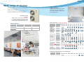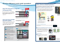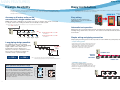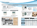
1
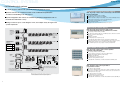
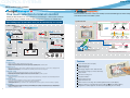
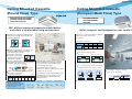
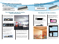
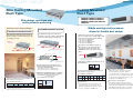
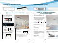
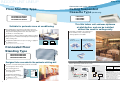
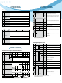
Warning
PCV0612F
Daikin products are manufactured for export to numerous countries throughout the world. Prior to
purchase, please confirm with your local authorised importer, distributor and/or retailer whether this
product conforms to the applicable standards, and is suitable for use, in the region where the product
will be used. This statement does not purport to exclude, restrict or modify the application of any local
legislation.
Ask a qualified installer or contractor to install this product. Do not try to install the product yourself.
Improper installation can result in water or refrigerant leakage, electrical shock, fire or explosion.
Use only those parts and accessories supplied or specified by Daikin. Ask a qualified installer or
contractor to install those parts and accessories. Use of unauthorised parts and accessories or
improper installation of parts and accessories can result in water or refrigerant leakage, electrical
shock, fire or explosion.
Read the User's Manual carefully before using this product. The User's Manual provides important
safety instructions and warnings. Be sure to follow these instructions and warnings.
If you have any enquiries, please contact your local importer, distributor and/or retailer.
Cautions on product corrosion
1. Air conditioners should not be installed in areas where corrosive gases, such as acid gas or alkaline gas, are produced.
2. If the outdoor unit is to be installed close to the sea shore, direct exposure to the sea breeze should be avoided. If you need to install
the outdoor unit close to the sea shore, contact your local distributor.
JMI-0107
Organization:
DAIKIN INDUSTRIES, LTD.
AIR CONDITIONING MANUFACTURING DIVISION
Organization:
DAIKIN INDUSTRIES
(THAILAND) LTD.
Scope of Registration:
THE DESIGN/DEVELOPMENT AND MANUFACTURE OF
COMMERCIAL AIR CONDITIONING, HEATING, COOLING,
REFRIGERATING EQUIPMENT, HEATING EQUIPMENT,
RESIDENTIAL AIR CONDITIONING EQUIPMENT, HEAT
RECLAIM VENTILATION, AIR CLEANING EQUIPMENT,
COMPRESSORS AND VALVES.
Scope of Registration:
THE DESIGN/DEVELOPMENT
AND MANUFACTURE OF AIR
CONDITIONERS AND THE
COMPONENTS INCLUDING
COMPRESSORS USED FOR THEM
JQA-1452
All of the Daikin Group’s business
facilities and subsidiaries in Japan
are certified under the ISO 14001
international standard for
environment management.
A special air conditioning system designed
for small offices and shops
Dealer
Head Office:
Umeda Center Bldg., 2-4-12, Nakazaki-Nishi,
Kita-ku, Osaka, 530-8323 Japan
Tokyo Office:
JR Shinagawa East Bldg., 2-18-1, Konan,
Minato-ku, Tokyo, 108-0075 Japan
http://www.daikin.com/global_ac/
c All rights reserved
08/12 Y.K.
Specifications, designs and other content appearing in this brochure are current as of August 2012 but subject to change without notice.
COOLING ONLY
HEAT PUMP
Cooling Only 50 Hz/60 Hz
Heat Pump 50 Hz/60 Hz
The ideal air conditioning system for
small offices and shops
Extending the core “5S” concept—Space saving, Sufficient capacity, Slim design, Soundreduced operation and Single phase power supply—Daikin’s VRVIII-S offers added value
with the “1E” concept—Easy installation. With all these features and more, we proudly
present the ideal air conditioning system designed for small-sized buildings.
Volume
Slim, compact and sufficient capacity
Approx.
765 mm
The
5S+1E concepts of
50%
reduction
The VRVIII-S is highly space saving, featuring slim and compact
outdoor units. It is suitable for small offices and shops with capacities
of 4, 5 and 6 HP.
320 mm
Footprint
635 mm
VRVIII
(5 HP)
Approx.
40%
900 mm
reduction
(4, 5, 6 HP)
VRVIII
(5 HP)
(4, 5, 6 HP)
S
5S
concept
Space saving
Sufficient capacity
Slim design
Sound-reduced operation
Single phase power supply
Easy installation
E
Outdoor unit can be installed
on a balcony
The compact, trunk-shaped outdoor unit can easily
be installed on a balcony, realising complete system
installation within each floor. This enables more
useful utilisation of the space on the building rooftop.
1E
concept
Contents
Introduction.......... page 1 Indoor unit lineup..... page 15 Option list............ page 33
Main features........ page 3 Specifications........... page 25
1
Control systems... page 9
Indoor units............... page 25
Outdoor units............ page 32
Indoor units......... page 33
Outdoor units.......page 35
Control systems...page 35
2
MAIN FEATURES
Wide range of choices
Indoor units
To suit the variety of rooms found in small offices
and shops, the VRVIII-S system offers wide range of
indoor and outdoor units.
VRVIII-S indoor and outdoor units are almost as easy
to install as residential air conditioning systems,
making them ideal for small offices and shops.
14 types 71 models*
A wide range of indoor units includes
71 models in 14 types. The indoor
units can be selected to match every
room and preference.
Outdoor units
3 models
Outdoor unit can be selected from three
models to provide the power that suits
your needs. The trunk-shaped outdoor unit
can be neatly installed outside the office.
Indoor unit lineup 14 types 71 models*
Outdoor unit lineup
Model Name
20
RX(Y)MQ4PVE
RX(Y)MQ5PVE
RX(Y)MQ6PVE
Type
Model Name
Capacity Index
Capacity Range
4 HP (11.2 kW)
5 HP (14.0 kW)
6 HP (15.5 kW)
Capacity Index
100
125
140
Ceiling Mounted
Cassette
(Round Flow)
Ceiling Mounted
Cassette
(Compact Multi Flow)
Ceiling Mounted
Cassette
(Double Flow)
25
32
40
50
Capacity Range 0.8 HP 1 HP 1.25 HP 1.6 HP 2 HP
100
125
140
2.5 HP 3.2 HP 4 HP
5 HP
6 HP
125
140
63
20
25
31.25
40
50
62.5
New
New
New
New
New
New
80
80
100
FXFQ-PVE
FXZQ-MVE
FXCQ-MVE
Ceiling Mounted
Cassette Corner
FXKQ-MAVE
FXDQ-PBVE
(with drain pump)
FXDQ-PBVET
(without drain pump)
Slim Ceiling
Mounted Duct
(700 mm width type)
FXDQ-NBVE
(with drain pump)
FXDQ-NBVET
(without drain pump)
Ceiling Mounted
Duct
FXMQ-PVE
Ceiling Suspended
Wall Mounted
(900/1,100 mm width type)
FXHQ-MAVE
New
FXAQ-PVE
Floor Standing
FXLQ-MAVE
Concealed
Floor Standing
FXNQ-MAVE
Note: R-410A VRV system indoor units are not compatible with the R-22 VRV system.
*13 types and 68 models for 60 Hz specifications.
Connection unit series indoor units (50 Hz only)
Type
Ceiling Suspended
Cassette
Model Name
Capacity Range
Capacity Index
Connection Unit
0.8 HP
20
1 HP
25
1.25 HP
31.25
1.6 HP
40
2 HP
50
—
3 HP
71
BEVQ71MAVE
4 HP
100
5 HP
125
BEVQ100MAVE BEVQ125MAVE
FXUQ-MAV1
Note: BEV units are necessary for Connection unit series indoor units. Refer to the Engineering Data Book for details.
3
4
MAIN FEATURES
Energy efficiency and quiet operation
Outdoor units use Daikin’s unique scroll compressor to realise energy saving
performance and quiet operation.
A collection of cutting-edge technologies
realises efficient and quiet operation.
The high efficiency compressor to achieve a higher COP
1
High COP
achieved
in all ranges!
High COP during both cooling and
heating operations
Cooling
Heating
VRVII-S
Previous model
RXYM-MVM
4 HP
3.65
5 HP
3.28
6 HP
2.92
3.68
4 HP
5 HP
3.41
6 HP
3.19
Above values are based on the following nominal conditions:
• 2 Ceiling Mounted Cassette (Round Flow) type units are connected (4 HP:
FXFQ50P x 2; 5 HP: FXFQ63P x 2; and 6 HP: FXFQ63P + FXFQ80P.)
• Cooling: Indoor temp. of 27°CDB, 19°CWB, and outdoor temp. of 35°CDB.
• Heating: Indoor temp. of 20°CDB, and outdoor temp. of 7°CDB, 6°CWB.
Quiet operation provides
luxurious comfort
Quietness is yet another important feature
of Daikin’s VRVIII-S system. To reduce
noise and realise comfortable operation,
latest technologies and features are
applied to the outdoor units.
51
-1dB(A)
5 HP
52
-1dB(A)
50
51
1
Reluctance DC motor
80
Conventional DC motor
70
More than 20%
60
AC motor
0
30
60
90
RX(Y)MQ4PVE
RX(Y)MQ5PVE
RX(Y)MQ6PVE
120
Reluctance
DC motor
Rotational speed (rps)
Small load
Low capacity
Large load
High capacity
Note: Data are based on studies conducted under
controlled conditions at a Daikin laboratory
using Daikin products.
*1 A neodymium magnet is approximately 10 times
stronger than a standard ferrite magnet.
*2 The torque created by the change in power
between the iron and magnet parts.
Previous model
RXYM-MVM
4 HP
2
90
50
Lower operation sound is achieved
in cooling operation!
1 dB(A) reduced
in each model!
VRVII-S
Cooling
3
Daikin DC inverter models are equipped with the Reluctance DC
motor for compressor. The Reluctance DC motor uses 2 different
types of torque, neodymium magnet*1 and reluctance torque*2. This
motor can save energy because it generates more power with a
smaller electric power than an AC or conventional DC motor.
Motor efficiency (%)
One of the top features of the VRVIII-S is
its energy efficiency. It achieves high COP
during cooling and heating operations by
employing Daikin’s unique scroll
compressor.
Compressor equipped with Reluctance DC motor
>> Smooth sine wave DC inverter
Sine wave DC inverter
Use of an optimised sine wave smoothes motor rotation, further improving
operating efficiency.
Nighttime quiet operation function
2
Mode 1. Automatic mode
Mode 3. Combined mode
Combinations of modes 1 and 2 can be used
depending on your needs.
*1. Initial setting. Can be selected from 6, 8 and 10 hours.
*2. Initial setting. Can be selected from 8, 9 and 10 hours.
Capacity %
Load %
Operation sound dB(A)
Mode 2. Manual mode
Starting time and ending time can be input. (An external
control adaptor for outdoor unit, DTA104A61 or
DTA104A62, and a locally obtained timer are
necessary.)
Peak in outdoor temperature
100
8 hrs
10 hrs
(Initial setting)
50
(Initial setting)
0
50
3
Night Mode
Step 1 max. - 3 dB(A)
( 4 HP/11.2 kW)
Step 1: 47 dB(A)
Step 2 max. - 6 dB(A)
( 4 HP/11.2 kW)
Step 2: 44 dB(A)
Step 3 max. - 9 dB(A)
( 4 HP/11.2 kW)
Step 3: 41 dB(A)
41
Night mode starts
8:00
12:00
16:00
20:00
DC fan motor structure
Night mode ends
0:00
4:00
8:00
Note: • This function is available in setting at site.
• The relationship of outdoor temperature (load) and time shown in the
graph is just an example.
The capacity reduction rate differs depending on the operation sound level
step selected.
5
Without the bent
blade edge
Escaping eddies are sucked in by
the bent blade edges, reducing
overall turbulence.
DC fan motor
Efficiency improved in all areas compared
to conventional AC motors, especially at
low speeds.
47
44
With the bent
blade edge
These two features work to reduce sound.
Guides are added to the bell mouth intake to
reduce turbulence in the airflow generated by
fan suction. The Aero Spiral Fan features fan
blades with the bent blade edges, further
reducing turbulence.
Mode 1. Automatic mode
Set on the outdoor PCB. Time of maximum
temperature is memorised. The low operating mode
will become active 8 hours*1 after the peak
temperature in the daytime, and operation will return to
normal 10 hours*2 after that. The operation sound
level for the night mode can be selected from 47 dB(A)
(Step 1), 44 dB(A) (Step 2) and 41 dB(A) (Step 3).
Smooth Air Inlet Bell Mouth and Aero Spiral Fan
DC motor efficiency
(comparison with AC motor)
100
Efficiency (%)
Operation sound level selectable
from 3 steps for the night mode
80
DC motor
60
Approx.
20%
increase
40 Approx.
40%
AC motor
Note: Data are based on
studies conducted under
controlled conditions at
0
a Daikin laboratory.
200 300 400 500 600 700 800 900 1000
Motor speed (rpm)
20 increase
6
MAIN FEATURES
Design flexibility
Easy installation
VRVIII-S systems offer broad design flexibility with long refrigerant piping lengths and
multiple indoor unit combinations, which provides generous freedom for office and shop
design both inside and out.
A variety of functions are provided that make installation easier, such as simple wiring
and piping and automatic test operation.
Previous model
VRVII-S
Easy wiring
As many as 9 indoor units can be
connected to a single outdoor unit
Multiple indoor unit combinations are possible.* As many as 9 indoor units can be connected
to a single outdoor unit, making the VRVIII-S a remarkably versatile system.
A printed circuit board has been
adopted that is easy to see and wire
during installation.
* Total capacity index of connectable indoor units must be 50 - 130 % of the capacity index of the outdoor unit.
For a 6 HP installation
Automatic test operation
1
2
3
4
Max.
9
units
>> Max. 8 indoor units for a 5 HP
Simply press the test operation button and the unit performs an automatic system check,
including wiring, shutoff valves, and sensors. The results are returned automatically after the
check finishes.
installation
5
6
7
8
9
>> Max. 6 indoor units for a 4 HP
Simple wiring and piping connection
installation
Unique piping and wiring systems make it possible to install a VRVIII-S system quickly and easily.
Long piping design possible
>> Super wiring system
The VRVIII-S provides the long piping
length possibility of 150 m, with a total piping
length of 300 m. If the outdoor unit is
installed above indoor units the level
difference can be up to a maximum of 50 m.
These generous allowances facilitate an
extensive variety of system designs.
Actual piping length
Max.
150
m
*2
Max.
50 m*1
Level
difference
Max.
A super wiring system is used to enable shared use of the
wiring between indoor and outdoor units and the central
control wiring, with a relatively simple wiring operation.
The DIII-NET communication system is employed to
enable the use of advanced control systems.
15 m
Level difference
between indoor
units
Outdoor unit
Central
remote
controller
Total piping length
Max.
300
m
Notes: *1. 40 m when the outdoor unit is installed below indoor units.
*2. Maximum piping length between the indoor unit and the first branch is 40 m.
Indoor unit
>> REFNET piping system
Certified operation temperature range
The versatile operation range of the VRVIII-S system
works to reduce limitations on installation locations. The
operation temperature range for heating goes all the way
down to -20°C, while cooling can be performed with
outdoor temperatures as high as 46°C. Both these
achievements are due to the adoption of a high-pressure
dome-type compressor.
7
Outdoor temperature (°CDB)
50
46°CDB
40
30
20
10
0
-10
-5°CDB
Cooling
Outdoor temperature (°CWB)
Wide operation temperature range
20
Daikin’s advanced REFNET piping system makes
installation easy. Only two main refrigerant lines are
required in any one system. REFNET greatly reduces the
imbalances in refrigerant flow between units, while using
small-diameter piping.
15.5°CWB
10
0
-10
-20
–20°CWB
Heating
8
CONTROL SYSTEMS
Control systems
The VRVIII-S system uses the same DIII-NET communication system as the
VRV, enabling the use of advanced control systems.
Individual control systems
Navigation remote controller (Wired remote controller) (Option)
Wireless remote controller (Option)
The same operation modes and settings as with wired remote controllers are possible.
A compact signal receiver unit (separate type) to be mounted into a wall or ceiling is
included.
Large buttons and arrow keys for easy operation.
Guide on display gives an explanation of each setting.
Backlight and dot matrix LCD display for easy viewing.
Weekly schedule timer can be set up easily.
10 display languages are available.
(English, German, French, Spanish, Italian, Portuguese, Greek, Dutch,
Russian and Turkish)
• A signal receiver unit (installed type) for a Ceiling Mounted Cassette (Round Flow,
Compact Multi Flow, Double Flow) type, Ceiling Suspended type and Wall Mounted
type is mounted into the indoor unit.
Signal receiver unit can be
installed on the panel
ex. Ceiling Mounted Cassette (Round Flow) type
Signal receiver unit
BRC1E61
(Separate type)
Wired remote controller (Option)
Wired remote controller
with weekly schedule timer (Option)
Displays current airflow, swing, temperature,
operating mode and timer settings.
Adds weekly schedule timer function.
Signal receiver unit
Wireless remote
controller
(Installed type)
*Wireless remote controller and signal receiver unit are sold as a set.
*Refer to page 35 for the name of each model.
Simplified remote controller (Option)
BRC1D61
Notes: 1. Standard remote controllers (BRC1C62) not required.
2. If the BRC1D61 is connected to the centralised remote controllers
(DCS303A51, DCS302CA61, DCS301BA61, DST301BA61), the
schedule function is not available.
BRC1C62
The remote controller has
centralised its frequently used
operation selectors and switches
(on/off, operation mode,
temperature setting and airflow
volume), making itself suitable
for use in hotel rooms or
conference rooms.
The exposed type remote
controller is fitted with a
thermostat sensor.
Concealed type
(For hotel use)
(BRC3A61)
Exposed type
The concealed type remote controller smartly fits into a
night table or console panel in a hotel room.
(BRC2C51)
The wired remote controller supports a wide range of control functions
Control of Cool/Heat In all the series of VRV, Cool/Heat changeover in the same refrigerant
circuit can be changed by the remote controller of the indoor unit.
changeover
1
The indoor unit can be connected by the two
remote controller, for example one in the room
and the other one in the control room, which
can control the operation of indoor unit freely.
(The last command has a priority.) Of course,
the group control by two remote controller is
also possible.
Group control
One remote controller can
control the operation of max.16
indoor units at the same time.
Equipment
related to the
central control
Outdoor
unit
Control by two remote controller
Wide variation of remote controllers for indoor units
FXFQ
FXZQ
FXCQ
FXKQ
FXDQ
FXMQ
FXHQ
FXAQ
FXL(N)Q
FXUQ
Navigation remote controller
(Wired remote controller)
(BRC1E61)
Wired remote controller
(BRC1C62)
2
Indoor unit
Remote controller
Remote controller
Remote control
The wiring of remote controller can be
extended to max. 500 m and it is possible
to install the remote controllers for the
different indoor units in one place.
Wired remote controller with
weekly schedule timer
(BRC1D61)
Wireless remote controller*
(Installed type signal receiver unit)
Remote
controller
3 Control for the combined operation
Forced OFF
input
Heat Reclaim
Ventilator
Remote
controller
Remote controller
1
9
2
Remote controller
3
Wireless remote controller*
(Separate type signal receiver unit)
Simplified remote controller
Remote controller
Remote controller
The operation of Heat Reclaim Ventilator can
be controlled by the remote controller of the
indoor unit. Of course, the remote controller
can display the time to clean the filter.
4
4
Expansion of system control
The system can be expanded to add
several controllers, such as BMS, Forced
OFF input and etc.
Refer to page 7 for the total number of indoor units that can be connected to the outdoor unit.
(Exposed type)
(BRC2C51)
Simplified remote controller
(Concealed type: for Hotel use)
(BRC3A61)
*Refer to page 35 for the name of each model.
10
CONTROL SYSTEMS
Centralised control systems
Up to 64 groups of indoor units (128 units) can be centrally controlled.
Residential central remote controller* (Option)
Optional controllers for centralised control can be combined and optimised in
accordance with building scale and purpose.
Max. 16 groups of indoor units can be easily controlled with
the large LCD panel.
Max. 16 groups (128 indoor units) controllable
Backlight and large LCD panel for easy readability
ON/OFF, temperature settings and scheduling can be controlled individually for indoor units.
All indoor units can be turned on or off at once with “ALL” button.
Each group has a dedicated button for convenience.
Outside temperature display
System integration with various air-conditioning peripheral equipment such as
Heat Reclaim Ventilator is easy.
Wiring can be run up to a total length of 2 km, and adapts easily to large-scale
system expansion.
DCS303A51
*For residential use only. Cannot be used with other centralised control equipment.
Central remote controller (Option)
Max. 64 groups (zones) of indoor units can be
controlled individually same as LCD Remote controller.
Unified on/off
controller
(DCS301BA61)
Connection of
up to 8 units
possible
Independent
and centralised
control of Heat
Reclaim
Ventilator is
possible.
Address setting of central control can be
performed from the remote controller.
DCS302CA61
Connectable number of
centralised control
equipment
Central remote
controller
2 units
Unified on / off
controller
8 units
Schedule timer
1 unit
Max. 64 groups (128 indoor units) controllable
Max. 128 groups (128 indoor units) are controllable by using 2 central remote controllers,
which can control from 2 different places.
Zone control
Malfunction code display
Max. wiring length 1,000 m (Total: 2,000 m)
Connectable with Unified ON/OFF controller, schedule timer and BMS system
Airflow volume and direction can be controlled individually for indoor units in each group operation.
Ventilation volume and mode can be controlled for Heat Reclaim Ventilator.
Up to 4 ON/OFF pairs can be set per day by connecting a schedule timer.
Group control of up to 16 units is possible 1
(group control via automatic address setting)
Unified ON/OFF controller (Option)
Max. 16 groups of indoor units can be operated
simultaneously/individually.
System without remote control is also available.
Forced
shut-down
input
Central remote
controller
(DCS302CA61)
Central control
adaptor kit
(DTA107A55)
Wiring adaptor
for other airconditioners
(DTA103A51)
Outdoor-air
processing
unit can be
connected.
DCS301BA61
Interface adaptor for SkyAir
series (built-in indoor unit)
(DTA102A52)
Up to 2 units
connectable
Schedule timer (Option)
6 cores
Schedule timer (DST301BA61)
1 unit connection possible;
8 weekly schedule control patterns possible
7 cores max.
Max. 128 indoor units can be operated as
programmed schedule.
Interlink Building Management System
(host computer monitor panel) also possible
Unification adaptor for computerised
control (DCS302A52)
1. Refer to page 7 for the total number of indoor units that can be connected to the outdoor unit.
• Certain indoor units limit the functions of some control systems.
For more details, please refer to the Engineering Data Book.
DST301BA61
11
Max. 16 groups (128 indoor units) controllable
2 remote controllers can be used to control from 2 different places.
Operating status indication (Normal operation, Alarm)
Centralised control indication
Max. wiring length 1,000 m (Total: 2,000 m)
Compact size casing (Thickness: 16 mm)
Connectable with Central Remote controller, Schedule timer and BMS system
Max. 128 indoor units controllable
When used in combination with a central remote controller, a maximum of 8 weekly schedule
patterns can be set, while the central controller can be used to select desired zones. Up to 2
ON/OFF pairs can be set per day.
Max. 48 hours back up power supply
Max. wiring length 1,000 m (Total: 2,000 m)
Compact size casing (Thickness: 16 mm)
Connectable with Central Remote controller, Unified ON/OFF controller and BMS system
12
CONTROL SYSTEMS
Advanced control systems
New
Communication functions in the user-friendly icon-based multilingual controller simplify
centralised control of the VRV system.
One touch selection to total air comfort
Daikin proudly introduces its new intelligent Touch Manager, a VRV system controller
featuring an array of simple, useful system management functions for added value.
Up to 2,560 groups (5,120 indoor units) can be controlled by one system
system overview
Dio Unit
DEC102A51
(Option)
system overview
Internal modem
(option)
New
DCS601C51
System
DCM601A51
Air Conditioning
Network Service System
Max. 64 groups
line
Phone line
Input
(Lights)
Di Unit
DEC101A51
(Option)
Input (Key signal General purpose ADP)
OFF
command
Set temperature
change command
LAN
Internet
Intranet
iTM plus adaptor line
Max. 50m
LAN
iTM plus adaptor (Max. 7 adaptors)
I/O expansion line
Air Conditioning Network
Service System modem
for connections
Max. 500m
USB memory
Via internet
RS-232C
Di/Pi line
Max. 200m
Web Access
ACC centre
I/O module I/O module I/O module
Web Access
• Air Conditioning Network Service System
(Optional Maintenance Service)
D -NET Plus Adaptor
DCS601A52 (Option)
Indoor Unit
Heat Reclaim
Ventilator
Number of indoor units expanded from 64 to 128.
kWh meter
Lighting
Pump
Fan
Sensor
Features
Central control
• Handy area settings simplify detailed management of VRV.
• Display of floor plans enables a quick search of desired air conditioning units.
• Operation history shows manner of control and origin in past operations of air conditioning units.
Remote access
• Remote access with a PC allows total air conditioning management using the same type of screens as those displayed in the
intelligent Touch Manager.
• Authorised users can centrally control individual air conditioning units from their own computers.
Automatic control
• VRVs are controlled automatically throughout the year by the schedule function.
• Interlocking VRVs and other equipment enables easy automation of building facilities operation.
• Setback adjusts temperature settings even when rooms are unoccupied.
Energy management
• The Energy Navigator feature simplifies energy management by tracking energy consumption data and identifying inefficient
operation.
Troubleshooting
• Contact information of maintenance contractors can be registered and displayed.
• E-mails are sent automatically to alert of malfunctions and potential trouble.
• The intelligent Touch Manager can link to the Air Conditioning Network Service System for 24-hour monitoring of operating
conditions and status.
Scalability
• A single intelligent Touch Manager can manage a small building or be expanded to handle medium- to large-sized buildings.
• Large building properties can also take advantage of the iTM integrator to link up and expand system up to 5 intelligent Touch
Managers for integrated control.
13
System
Components
I/O System (Max. 30 modules)
Fire alarm
D -NET
Di/Pi port
Features
Colour LCD touch panel icon display
Small manageable size
Simplified engineering
Multi language (English, French, Italian, German,
Spanish, Dutch, Portuguese, Chinese and Korean)
Yearly schedule
Auto heat/cool change-over
Temperature limitation
Enhanced history function
Simple Interlock Function
Built-in modem for connecting to Air Conditioning Network Service System (Option)
Doubling of number of connectable indoor units by adding a D -NET Plus Adaptor (Option)
Management of facilities/equipment other than A/C units (By adding Dio unit or Di unit)
14
INDOOR UNIT LINEUP
Ceiling Mounted Cassette
(Compact Multi Flow) Type
Ceiling Mounted Cassette
(Round Flow) Type
FXFQ25P/ FXFQ32P/ FXFQ40P
FXFQ50P/ FXFQ63P/ FXFQ80P
FXFQ100P/ FXFQ125P
FXZQ20M/FXZQ25M
FXZQ32M/FXZQ40M
FXZQ50M
360° airflow improves temperature distribution
and offers a comfortable living environment.
Quiet, compact, and designed for user comfort
Dimensions correspond with 600 mm X 600 mm
architectural module ceiling design
specifications.
The industry’s first* Round Flow Ceiling Mounted
Cassette type offers 360° airflow with improved
temperature distribution.
Round Flow
4-way flow
Low operation sound level
There are areas of
uneven temperature.
There are much fewer
areas of uneven temperature.
(dB(A))
FXZQ-M
20/25
32
40
50
Sound level 230 V
(H/L)
240 V
30/25
32/26
36/28
41/33
32/26
34/28
37/29
42/35
*As of April 2004, the release date for Japan.
All models are lighter than the conventional ones.
Ex: Models FXFQ25P-50P are 4.5 kg lighter
(reduced from 24 kg to 19.5 kg).
Drain pump is equipped as
standard accessory, and the
850 mm
lift height has been improved
from 750 mm to 850 mm.
A modern sophisticated decoration panel has
been applied, with a panel surface that has been
treated with a dirt-repellant coating.
Treated surface
Untreated surface
Dirt and
grime • Condition after
exposure to the
smoke of 600
3
cigarettes in 1 m
enclosed space.
Resists
soiling
Control of the airflow rate has been improved
from 2-step to 3-step control.
Low operation sound level
FXFQ-P
25/32
40
50
(dB(A))
63
80
100
125
Sound
level
30/28.5/27 31/29/27 32/29.5/27 34/31/28 36/33.5/31 43/37.5/32 44/39/34
(HH/H/L)
Example of airflow patterns:
All-round flow
Comfortable airflow
Wide discharge angle: 0° to 60°
1
Fixed angles: 5 levels
Auto swing
0°
An antibacterial treatment that uses silver ions
has been applied to the drain pan, preventing
the growth of slime, mould and bacteria that
cause blockages and odours.
The horizontal louvres prevent dew
condensation. Their non-flocking surfaces, which
repel dirt, are easy to clean.
The air filter has an anti-mould and antibacterial
treatment that prevents the growth of mould
generated from dust or moisture that may
adhere to the filter.
4-way flow
3-way flow
L-shaped 2-way flow
0°
60°
0°
60°
0°
60°
60°
Angles can be also set on site to prevent drafts (0°-35°)
or soiling of the ceiling (25°-60°), other than standard setting (0°-60°).
2
2-, 3-, and 4-way airflow patterns are available,
enabling installation in the corner of a room.
Drain pump is equipped as standard
accessory with 750 mm lift.
4-way flow
3-way flow
L-shaped
2-way flow
750 mm
For 3-way or 2-way flow installation, the sealing member for air discharge
outlet (option) must be used to close each unused outlet.
360° airflow is available, as well as 2- to
4-way flows, so you can choose the most
suitable airflow pattern depending on
location or room layout.
Note: Whatever the discharge direction, the same type of panel is used. If installing for other than all-round flow, an air discharge outlet sealing member (option) must be used to close each unused outlet.
15
16
INDOOR UNIT LINEUP
Ceiling Mounted Cassette
Corner Type
Ceiling Mounted Cassette
(Double Flow) Type
FXKQ25MA/FXKQ32MA
FXKQ40MA/FXKQ63MA
FXCQ20M/ FXCQ25M / FXCQ32M
FXCQ40M/ FXCQ50M / FXCQ63M
FXCQ80M/ FXCQ125M
Thin, lightweight, and easy to install in
shallow ceiling spaces
Slim design for flexible installation
Slim body needs only 220 mm space above
the ceiling. If you use a panel spacer (option),
the unit can be installed in the minimum space
of 195 mm.
The low profile unit (only 305 mm high) can
be installed in a ceiling space as shallow
as 350 mm. All models feature a compact
design with a depth of only 600 mm.
Min.195 mm
305 mm
Panel spacer
20 mm
(When a high-efficiency filter is attached, the
unit's height is 400 mm.)
Single-flow type allows effective air discharge
from corner or from drop-ceiling.
Providing 3 different settings of standard,
draft prevention and ceiling soiling
prevention, the auto swing mechanism
achieves even distribution of airflow and
room temperature.
(m)
3
2
FXCQ-M
20
25/32 40/50
Drain pump is equipped as standard
accessory with 500 mm lift.
(dB(A))
63
80
125
Sound level 220 V 32/27 34/28 34/29 37/32 39/34 44/38
(H/L)
240 V 34/29 36/30 37/32 39/34 41/36 46/40
500 mm
26˚C
24˚C
22˚C
1
0
Low operation sound level
28˚C
32˚C 30˚C
20˚C
1
2
3
4
5
6 (m)
Front discharge is possible with an air
discharge unit (option), which allows the
installation in the drop-ceiling or sagging wall.
Main body
Designed with higher airflow suitable for
high ceiling application up to 3 metres.
Downward discharge
Air discharge grille (Option)
Providing 2 different settings of standard
and ceiling soiling prevention, the auto
swing mechanism achieves even
distribution of airflow and room
temperature.
Drain pump is equipped as standard
accessory with 600 mm lift.
Two types of optional high-efficiency filter are
available (65% and 95%, colourimetric method).
A long-life filter (maintenance free up to one
year ) is equipped as standard accessory.
Set for front discharge using a suspended ceiling.
Main body
Air discharge grille
(Option)
8 hr/day, 25 day/month. For dust concentration of 0.15 mg/m
3
600 mm
Major maintenance work can be performed by
removing the panel. A flat-type suction grille
and a detachable blade make cleaning easy.
Downward discharge is shut off and air is blown straight out
(front discharge).
A long-life filter (maintenance free up to one
year ) is equipped as standard accessory.
8 hr/day, 25 day/month. For dust concentration of 0.15 mg/m3
17
18
INDOOR UNIT LINEUP
Slim Ceiling Mounted
Duct Type
Ceiling Mounted
Duct Type
FXMQ20P/FXMQ25P/FXMQ32P
FXMQ40P/FXMQ50P/FXMQ63P
FXMQ80P/FXMQ100P/FXMQ125P
FXMQ140P
Slim design, quietness and
static pressure switching
Suited to use in drop-ceilings!
Middle and high static pressure
allows for flexible duct design
FXDQ40NB/FXDQ50NB/FXDQ63NB
FXDQ20PB/FXDQ25PB/FXDQ32PB
Only 700 mm in width and 23 kg in weight, this
model is suitable to install in limited spaces like
drop-ceilings in hotels.
Only 200 mm in height, this model can be
installed in rooms with as little as 240 mm depth
between the drop-ceiling and ceiling slab.
30 Pa–100 Pa for FXMQ20P-32P
30 Pa–160 Pa for FXMQ40P
50 Pa–200 Pa for FXMQ50P-125P
50 Pa–140 Pa for FXMQ140P
Great for
hotel use!
200 mm
900 mm
200 mm
Only
A DC fan motor increases the external static
pressure capacity range to include middle to high
static pressures, increasing design flexibility.
700 mm
1,100 mm in width for the FXDQ63NB model.
Suspension bolt*
All models are only 300 mm in height, an
improvement over the 390 mm height of
conventional models. The weight of the
FXMQ40P has been reduced from 44 kg to
28 kg.
Air filter
300 mm
240 mm
AIR
Discharge grille*
Easy installation in buildings
with narrow ceiling spaces
Suction grille*
AIR
*To be obtained locally
Drain pump is equipped as standard accessory
with 700 mm lift.
External static pressure selectable by remote
controller switching make this indoor unit a very
comfortable and flexible model.
10 Pa-30 Pa/factory set: 10 Pa for FXDQ-PB models.
15 Pa-44 Pa/factory set: 15 Pa for FXDQ-NB models.
FXDQ-PB and FXDQ-NB models are available in
two types to suit different installation conditions.
Control of the airflow rate has been improved
from 2-step to 3-step control.
Low operation sound level
(dB(A))
FXDQ-PB/NB
20/25/32
40
50
63
Sound level
(HH/H/L)
33/31/29
34/32/30
35/33/31
36/34/32
The values of operation sound level represent those for rear-suction operation.
Sound level values for bottom-suction operation can be obtained by adding 5 dB(A).
Values are based on the following conditions:
FXDQ-PB: external static pressure of 10 Pa; FXDQ-NB: external static pressure of 15 Pa.
19
FXDQ-PB/NBVE: with a drain pump (750 mm lift)
as a standard accessory
FXDQ-PB/NBVET: without a drain pump
750 mm
Ceiling
700 mm
Ceiling
Control of the airflow rate has been improved
from 2-step to 3-step control.
Low operation sound level
FXMQ-P 20/25
32
40
50
(dB(A))
63
80/100
125
140
Sound
level 33/31/29 34/32/30 39/37/35 41/39/37 42/40/38 43/41/39 44/42/40 46/45/43
(HH/H/L)
Energy-efficient
The adopted DC fan motor is much more
efficient than the conventional AC motor,
yielding an approximate 20% decrease in
energy consumption. (FXMQ125P)
Improved ease of installation
Airflow rate can be controlled using a remote
controller during test operation. With the
conventional model, the airflow rate was controlled
from the PC board. It is automatically adjusted to
the range between approximately ±10% of the rated
HH tap airflow for FXMQ20P-125P.
Improved ease of maintenance
The drain pan can be detached for easy
cleaning. An antibacterial treatment that uses
silver ions has been applied to the drain pan,
preventing the growth of slime, mould and
bacteria that cause blockages and odours.
20
INDOOR UNIT LINEUP
Ceiling Suspended Type
Wall Mounted Type
FXHQ32MA / FXHQ63MA
FXHQ100MA
Stylish flat panel design harmonised
with your interior décor
Slim body with quiet and wide airflow
Stylish flat panel design creates a graceful
harmony that enhances any interior space.
Adoption of QUIET STREAM FAN
Uses the quiet stream fan and many
advanced technologies.
Flat panel can be cleaned with only the single
pass of a cloth across their smooth surface.
Flat panel can also be easily removed and
washed for more thorough cleaning.
Sound absorption
material
Turbulent flow
is produced
Quiet stream fan
Low operation sound level
Straightening vane
Low operation sound level
FXAQ20P/FXAQ25P
FXAQ32P/FXAQ40P
FXAQ50P/FXAQ63P
New
(dB(A))
FXAQ-P
20
25
32
40
50
63
Sound level
(H/L)
35/31
36/31
38/31
39/34
42/37
47/41
(dB(A))
FXHQ-MA
32
63
100
Sound level
(H/L)
36/31
39/34
45/37
Drain pan and air filter can be kept clean by
mould-proof polystyrene.
Installation is easy
Drain pump kit (option) can be easily
incorporated.
Vertical auto-swing realises efficiency of air
distribution. The louvre closes automatically
when the unit stops.
600 mm
Drain pump kit
(built inside main unit)
Wide air discharge openings produce a
spreading 100° airflow.
Maintenance is easy
Non-dew Flap with no implanted bristles
Bristle-free Flap minimises
contamination and makes
cleaning simpler.
Easy-to-clean flat design
Non-dew Flap
Maintenance is easier because servicing can
be performed from below the unit.
A long-life filter (maintenance free up to one
year) is equipped as standard accessory.
100°
21
5 steps of discharge angle can be set by
remote controller.
Discharge angle is automatically set at the
same angle as the previous operation when
restarting. (Initial setting: 10˚ for cooling and
70˚ for heating)
Flexible installation
Drain pipe can be fitted to from either left or
right sides.
Drain pump kit is available as optional accessory,
which lifts the drain 1,000 mm from the bottom of
the unit.
Height of drain-up
1,000 mm
Drain pump kit
Indoor unit
22
INDOOR UNIT LINEUP
Connection unit series indoor units
Ceiling Suspended
Cassette Type (50 Hz only)
Floor Standing Type
FXLQ20MA / FXLQ25MA
FXLQ32MA/FXLQ40MA
FXLQ50MA / FXLQ63MA
FXUQ71MA
FXUQ100MA
FXUQ125MA
This thin indoor unit achieves optimum
air distribution, and can be installed
without the need for ceiling cavity
Suitable for perimeter zone air conditioning
Floor Standing types can be hung on the wall for easier floor
cleaning. Running the piping from the back allows the unit to be
hung on walls. Cleaning under the unit, where dust tends to
accumulate, is considerably easier.
Depending on installation site requirements or
room conditions, 2-way, 3-way and 4-way
discharge patterns are available.
The adoption of a fibre-less discharge grille featuring an original
design to prevent condensation also helps prevent staining and
makes cleaning easier.
4-way airflow
from the centre of the store.
A long-life filter (maintenance free up to one year ) is equipped
as standard accessory.
8 hr/day, 25 day/month. For dust concentration of 0.15 mg/m3
Wall hanging
The 3-way airflow can distribute
comfortable air throughout the room.
Floor installation
Concealed Floor
Standing Type
Only one unit is needed to distribute comfortable air
throughout an L-shaped store.
FXNQ20MA / FXNQ25MA
FXNQ32MA / FXNQ40MA
FXNQ50MA / FXNQ63MA
Designed to be concealed in the perimeter skirting-wall
Connection unit
Connection unit is the device for connecting above indoor unit to VRVIII-S.
BEVQ71MA/BEVQ100MA/BEVQ125MA
The unit is concealed in skirting-wall of perimeter, that enables
to create high class interior design.
The connecting port faces
downward, greatly facilitating
on-site piping work.
Refrigerant piping layout
External wiring layout
Connection unit for indoor unit
VRV -S series
outdoor unit
Connecting
port
Liquid
pipe
Gas pipe
BEVQ-MAVE
Super wiring (DIII-NET)
Single-phase 220-240 V
power supply
Indoor unit
A long-life filter (maintenance
free up to one year ) is equipped
as standard accessory.
8 hr/day, 25 day/month. For dust concentration of 0.15 mg/m3
23
Refrigerant
piping
Applies also to Floor Standing type (FXLQ-MA).
Piping length*1
Indoor unit
Remote controller
*1
Model
Maximum piping length
between the BEV unit
and the indoor unit.
FXUQ-MA
5m
Notes:
• When connecting centralised-control device, it is
necessary to install an interface adaptor for an
indoor unit (DTA102A52).
• Connection unit BEVQ-MA is necessary for each
indoor unit.
• The refrigerant piping height difference between
the indoor units and the BEV unit must be within
4 m.
• The BEV unit must be installed within a
maximum height difference between indoor units
of 15 m.
• Branching of the refrigerant piping is not
possible downstream of the BEV unit.
24
SPECIFICATIONS
INDOOR UNITS
Ceiling Mounted Cassette (Double Flow) Type
MODEL
Ceiling Mounted Cassette (Round Flow) Type
MODEL
Cooling capacity
kcal/h(*1)
2,500
3,200
4,000
5,000
6,300
8,000
10,000
12,500
Btu/h(*1)
9,900
12,600
16,000
19,800
24,900
31,700
39,600
49,500
(*1)
2.9
3.7
4.7
5.8
7.3
9.3
11.6
14.5
(*2)
2.8
3.6
4.5
5.6
7.1
9.0
11.2
14.0
kcal/h
Power consumption Cooling
(50 Hz/60 Hz)
Heating
2,800
3,400
4,300
5,400
6,900
8,600
10,800
10,900
13,600
17,100
21,500
27,300
34,100
42,700
54,600
kW
3.2
4.0
5.0
6.3
8.0
10.0
12.5
16.0
0.033/0.032 0.033/0.032 0.047/0.042 0.052/0.050 0.066/0.063 0.093/0.092 0.187/0.186 0.209/0.208
kW
0.027/0.027 0.027/0.027 0.034/0.034 0.038/0.038 0.053/0.053 0.075/0.075 0.174/0.174 0.200/0.200
Heating capacity
Power consumption Cooling
(50 Hz/60 Hz)
Heating
Airflow rate (HH/H/L)
cfm
Sound level (HH/H/L)
Dimensions (HXWXD)
Machine weight
Liquid (Flare)
Piping
connections Gas (Flare)
Drain
dB(A)
mm
kg
mm
13/11.5/10 13/11.5/10 15/13/11 16/13.5/11 19/16.5/13.5 21/18/15
459/406/353 459/406/353 530/459/388 565/477/388 671/583/477 742/636/530 1,130/918/706 1,165/989/794
30/28.5/27 30/28.5/27 31/29/27 32/29.5/27 34/31/28 36/33.5/31 43/37.5/32
19.5
19.5
19.5
19.5
22
6.4
6.4
6.4
6.4
9.5
9.5
9.5
9.5
12.7
12.7
12.7
12.7
15.9
15.9
15.9
15.9
22
25
25
VP25 (External Dia, 32/Internal Dia, 25)
BYCP125K-W1
Colour
Fresh white
Weight
44/39/34
mm
kg
Sound level (H/L)
Heating capacity
Power consumption Cooling
(50 Hz/60 Hz)
Heating
5.5
5.5
5.5
Piping
connections Gas (Flare)
Drain
5.5
5.5
5.5
5.5
5.5
2,000
2,500
3,200
4,000
5,000
7,800
9,900
12,600
16,000
19,800
(*1)
2.3
2.9
3.7
4.7
5.8
(*2)
2.2
2.8
3.6
4.5
5.6
kcal/h
2,200
2,800
3,400
4,300
5,400
Btu/h
8,500
10,900
13,600
17,100
21,500
kW
2.5
3.2
4.0
5.0
6.3
0.073/0.075
0.073/0.075
0.076/0.080
0.089/0.095
0.115/0.128
0.064/0.069
0.064/0.069
0.068/0.073
0.080/0.088
0.107/0.122
cfm
Dimensions (HXWXD)
Machine weight
dB(A)
Piping
connections Gas (Flare)
Drain
Panel
(Option)
318/247
9/7
318/247
9.5/7.5
335/265
286X575X575
kg
18
388/282
14/10
19,800
24,900
31,700
49,500
(*1)
2.3
2.9
3.7
4.7
5.8
7.3
9.3
14.5
(*2)
2.2
2.8
3.6
4.5
5.6
7.1
9.0
14.0
kcal/h
2,200
2,800
3,400
4,300
5,400
6,900
8,600
13,800
Btu/h
8,500
10,900
13,600
17,100
21,500
27,300
34,100
54,600
kW
2.5
3.2
4.0
5.0
6.3
8.0
10.0
16.0
0.077/0.081 0.092/0.095 0.092/0.095 0.130/0.132 0.130/0.132 0.161/0.157 0.209/0.216 0.256/0.278
kW
0.044/0.048 0.059/0.062 0.059/0.062 0.097/0.099 0.097/0.099 0.126/0.124 0.176/0.183 0.223/0.245
m3/min
7/5
9/6.5
9/6.5
12/9
12/9
16.5/13
26/21
33/25
cfm
247/177
318/230
318/230
424/318
424/318
582/459
918/741
1,165/883
32/27
34/28
34/28
34/29
34/29
37/32
39/34
44/38
34/29
36/30
36/30
37/32
37/32
39/34
41/36
46/40
mm
305X775X600
305X775X600
305X775X600
305X990X600
kg
26
26
26
31
dB(A)
mm
305X990X600 305X1,175X600 305X1,665X600 305X1,665X600
32
35
47
48
6.4
6.4
6.4
6.4
6.4
9.5
9.5
9.5
12.7
12.7
12.7
12.7
12.7
15.9
15.9
15.9
VP25 (External Dia, 32/Internal Dia, 25)
BYBC50G-W1
BYBC63G-W1
BYBC125G-W1
White (10Y9/0.5)
Dimensions (HXWXD)
mm
kg
53X1,030X680 53X1,030X680 53X1,030X680 53X1,245X680 53X1,245X680 53X1,430X680 53X1,920X680 53X1,920X680
8.0
8.0
8.0
8.5
8.5
9.5
12.0
12.0
Ceiling Mounted Cassette Corner Type
6.4
6.4
12.7
12.7
12.7
12.7
12.7
Cooling capacity
Heating capacity
BYFQ60B8W1
3,200
4,000
6,300
Btu/h (*1)
9,900
12,600
16,000
24,900
(*1)
2.9
3.7
4.7
7.3
(*2)
2.8
3.6
4.5
7.1
kcal/h
2,800
3,400
4,300
6,900
Btu/h
10,900
13,600
17,100
27,300
kW
Power consumption Cooling
(50 Hz/60 Hz)
Heating
kW
3.2
4.0
5.0
8.0
0.066/0.069
0.066/0.069
0.076/0.092
0.105/0.120
0.046/0.049
0.046/0.049
0.056/0.072
0.085/0.100
Galvanised steel plate
Casing
Airflow rate (H/L)
60 Hz
Sound level (H/L)
220 V
240 V
Piping
Gas (Flare)
connections
Drain
m3/min
11/9
11/9
13/10
18/15
cfm
388/318
388/318
459/353
635/530
m3/min
11/8.5
11/8.5
13/10
18/13
cfm
388/300
388/300
459/353
635/459
38/33
38/33
40/34
42/37
40/35
40/35
42/36
44/39
mm
215X1,110X710
215X1,110X710
215X1,110X710
215X1,310X710
kg
31
31
31
34
dB(A)
mm
6.4
6.4
6.4
9.5
12.7
12.7
12.7
15.9
VP25 (External Dia, 32/Internal Dia, 25)
Model
Panel
(Option)
55X700X700
55X700X700
55X700X700
55X700X700
55X700X700
kg
2.7
2.7
2.7
2.7
2.7
Note: Specifications are based on the following conditions;
•Cooling: Indoor temp.: (*1)27°CDB, 19.5°CWB, Outdoor temp.: 35°CDB, Equivalent piping length: 7.5 m, Level difference: 0 m.
(*2)27°CDB, 19°CWB, Outdoor temp.: 35°CDB, Equivalent piping length: 7.5 m, Level difference: 0 m.
•Heating: Indoor temp.: 20°CDB, Outdoor temp.: 7°CDB, 6°CWB, Equivalent piping length: 7.5 m, Level difference: 0 m.
•Capacity of indoor unit is only for reference. Actual capacity of indoor unit is based on the total capacity index. (See Engineering Data Book for details.)
•Sound level: Anechoic chamber conversion value, measured at a point 1.5 m downward from the unit centre.
During actual operation, these values are normally somewhat higher as a result of ambient conditions.
BYK45FJW1
Colour
Dimensions (HXWXD)
Weight
mm
FXKQ63MAVE
2,500
kW
VP20 (External Dia, 26/Internal Dia, 20)
FXKQ40MAVE
kcal/h (*1)
Liquid (Flare)
6.4
FXKQ32MAVE
1-phase, 220 - 240 V/220 V, 50/60 Hz
Machine weight
6.4
White (6.5Y9.5/0.5)
FXKQ25MAVE
Power supply
493/353
6.4
Colour
Dimensions (HXWXD)
11/8
30/25-32/26-32/29 30/25-32/26-32/29 32/26-34/28-33/29 36/28-37/29-36/30 41/33-42/35-41/34
Model
Weight
25
9/7
mm
mm
12,500
16,000
BYBC32G-W1
Dimensions (HXWXD)
Liquid (Flare)
8,000
12,600
Colour
50 Hz
Galvanised steel plate
230 V, 50 HzSound level
240 V, 50 Hz(H/L)
220 V, 60 Hz
6,300
9,900
MODEL
Btu/h(*1)
m3/min
5,000
7,800
Model
Weight
kcal/h(*1)
kW
4,000
Btu/h (*1)
Liquid (Flare)
1-phase, 220-240 V/220 V, 50 Hz/60 Hz
Casing
Airflow rate (H/L)
240 V
Machine weight
Panel
(Option)
FXZQ20MVE FXZQ25MVE FXZQ32MVE FXZQ40MVE FXZQ50MVE
kW
3,200
50X950X950 50X950X950 50X950X950 50X950X950 50X950X950 50X950X950 50X950X950 50X950X950
Power supply
Cooling capacity
220 V
Dimensions (HXWXD)
Ceiling Mounted Cassette (Compact Multi Flow) Type
MODEL
2,500
Galvanised steel plate
Airflow rate (H/L)
246X840X840 246X840X840 246X840X840 246X840X840 246X840X840 246X840X840 288X840X840 288X840X840
Model
Dimensions (HXWXD)
32/26/20 33/28/22.5
2,000
Casing
Galvanised steel plate
m3/min
kcal/h (*1)
kW
13,800
Btu/h
Casing
Panel
(Option)
1-phase, 220 - 240 V/220 V, 50/60 Hz
Cooling capacity
1-phase, 220-240 V/220 V, 50/60 Hz
kW
Heating capacity
Power supply
FXFQ25PVE FXFQ32PVE FXFQ40PVE FXFQ50PVE FXFQ63PVE FXFQ80PVE FXFQ100PVE FXFQ125PVE
Power supply
FXCQ20MVE FXCQ25MVE FXCQ32MVE FXCQ40MVE FXCQ50MVE FXCQ63MVE FXCQ80MVE FXCQ125MVE
BYK71FJW1
White (10Y9/0.5)
mm
70X1,240X800
70X1,240X800
70X1,240X800
70X1,440X800
kg
8.5
8.5
8.5
9.5
Note: Specifications are based on the following conditions;
•Cooling: Indoor temp.: (*1)27°CDB, 19.5°CWB, Outdoor temp.: 35°CDB, Equivalent piping length: 7.5 m, Level difference: 0 m.
(*2)27°CDB, 19°CWB, Outdoor temp.: 35°CDB, Equivalent piping length: 7.5 m, Level difference: 0 m.
•Heating: Indoor temp.: 20°CDB, Outdoor temp.: 7°CDB, 6°CWB, Equivalent piping length: 7.5 m, Level difference: 0 m.
•Capacity of indoor unit is only for reference. Actual capacity of indoor unit is based on the total capacity index. (See Engineering Data Book for details.)
•Sound level: Anechoic chamber conversion value, measured at a point 1.5 m downward from the unit centre.
During actual operation, these values are normally somewhat higher as a result of ambient conditions.
26
SPECIFICATIONS
Slim Ceiling Mounted Duct Type (700 mm width type)
MODEL
with
drain pump
without
drain pump
FXDQ20PBVE
FXDQ20PBVET
Power supply
FXDQ25PBVET
Btu/h(*1)
Cooling capacity
kW
(*1)
(*2)
kcal/h
Heating capacity
FXDQ32PBVET
2.3
9,900
2.9
3,200
2.2
2.8
3.6
2,200
2,800
3,400
13,600
kW
2.5
3.2
4.0
0.086/0.092
kW
0.086/0.092
0.067/0.073
0.070/0.076
0.067/0.073
0.067/0.073
0.070/0.076
0.067/0.073
m3/min
cfm
External static pressure
Sound level (HH/H/L) 2 3
Dimensions (HXWXD)
Machine weight
Liquid (Flare)
Piping
connections Gas (Flare)
Drain
8.0/7.2/6.4
282/254/226
282/254/226
33/31/29
33/31/29
8.0/7.2/6.4
282/254/226
33/31/29
200X700X620
200X700X620
200X700X620
kg
23
23
23
6.4
6.4
6.4
12.7
12.7
12.7
VP20 (External Dia, 26/Internal Dia, 20)
FXDQ40NBVE
FXDQ40NBVET
Power supply
Heating capacity
5,000
6,300
Btu/h(*1)
16,000
19,800
24,900
(*1)
4.7
5.8
7.3
(*2)
4.5
5.6
7.1
kcal/h
4,300
5,400
6,900
Btu/h
17,100
21,500
27,300
kW
Heating
kW
Cooling
Heating
kW
5.0
6.3
8.0
0.160/0.182
0.165/0.185
0.181/0.192
0.147/0.168
0.152/0.170
0.168/0.179
0.147/0.168
0.152/0.170
0.168/0.179
0.147/0.168
0.152/0.170
0.168/0.179
Casing
Galvanised steel plate
Airflow rate (HH/H/L)
External static pressure
Sound level (HH/H/L) 2 3
Dimensions (HXWXD)
Machine weight
m3/min
10.5/9.5/8.5
12.5/11.0/10.0
16.5/14.5/13.0
cfm
371/335/300
441/388/353
583/512/459
dB(A)
34/32/30
35/33/31
36/34/32
mm
200X900X620
200X900X620
200X1,100X620
kg
27
28
31
Liquid (Flare)
Piping
connections Gas (Flare)
Drain
44-15 1
Pa
mm
Airflow rate (HH/H/L)
Btu/h (*1)
7,800
9,900
12,600
16,000
19,800
(*1)
2.3
2.9
3.7
4.7
5.8
(*2)
2.2
2.8
3.6
4.5
5.6
kcal/h
2,200
2,800
3,400
4,300
5,400
Btu/h
8,500
10,900
13,600
17,100
21,500
kW
2.5
3.2
4.0
5.0
6.3
0.081/0.080
0.081/0.080
0.085/0.084
0.194/0.193
0.215/0.214
0.069/0.069
0.069/0.069
0.073/0.073
0.182/0.182
0.203/0.203
kW
m3/min
9/7.5/6.5
9/7.5/6.5
9.5/8/7
16/13/11
18/16.5/15
cfm
318/265/230
318/265/230
335/282/247
565/459/388
635/582/530
Pa
30-100
1
6.4
6.4
9.5
12.7
12.7
15.9
1
30-100
1
30-100
1
30-160
1
50-200
Sound level (HH/H/L)
dB(A)
33/31/29
33/31/29
34/32/30
39/37/35
41/39/37
Dimensions (HXWXD)
mm
300X550X700
300X550X700
300X550X700
300X700X700
300X1,000X700
kg
25
25
25
28
36
6.4
6.4
6.4
6.4
6.4
12.7
12.7
12.7
12.7
12.7
Liquid (Flare)
Piping
connections Gas (Flare)
Drain
mm
VP25 (External Dia, 32/Internal Dia, 25)
MODEL
Cooling capacity
FXMQ63PVE FXMQ80PVE FXMQ100PVE FXMQ125PVE FXMQ140PVE
1-phase, 220-240 V/220 V, 50/60 Hz
kcal/h (*1)
6,300
8,000
10,000
12,500
14,300
Btu/h (*1)
24,900
31,700
39,600
49,500
57,000
(*1)
7.3
9.3
11.6
14.5
16.7
(*2)
7.1
9.0
11.2
14.0
16.0
kcal/h
6,900
8,600
10,800
13,800
15,500
Btu/h
27,300
34,100
42,700
54,600
61,400
kW
8.0
10.0
12.5
16.0
18.0
0.230/0.229
0.298/0.297
0.376/0.375
0.461/0.460
0.461/0.460
0.218/0.218
0.286/0.286
0.364/0.364
0.449/0.449
0.449/0.449
39/33/28
46/39/32
kW
Heating capacity
4,000
Cooling
5,000
Galvanised steel plate
FXDQ63NBVET
kcal/h(*1)
kW
27
FXDQ50NBVET
4,000
Casing
FXDQ63NBVE
1-phase, 220-240 V/220 V, 50/60 Hz
Cooling capacity
Power consumption
(FXDQ-NBVE:
50 Hz/60 Hz)
Power consumption
(FXDQ-NBVET:
50 Hz/60 Hz)
FXDQ50NBVE
3,200
Power supply
Slim Ceiling Mounted Duct Type (900/1,100 mm width type)
with
drain pump
without
drain pump
Power consumption Cooling
(50 Hz/60 Hz)
Heating
Machine weight
mm
mm
Heating capacity
External static pressure
30-10 1
Pa
dB(A)
8.0/7.2/6.4
2,500
kW
0.070/0.076
Galvanised steel plate
Airflow rate (HH/H/L)
2,000
0.089/0.095
0.067/0.073
0.067/0.073
Cooling capacity
1-phase, 220-240 V/220 V, 50/60 Hz
kcal/h (*1)
3.7
10,900
kW
FXMQ20PVE FXMQ25PVE FXMQ32PVE FXMQ40PVE FXMQ50PVE
Power supply
12,600
8,500
Cooling
Heating
7,800
2,500
Btu/h
Cooling
Heating
2,000
Casing
MODEL
MODEL
FXDQ32PBVE
1-phase, 220-240 V/220 V, 50/60 Hz
kcal/h(*1)
Power consumption
(FXDQ-PBVE:
50 Hz/60 Hz)
Power consumption
(FXDQ-PBVET:
50 Hz/60 Hz)
FXDQ25PBVE
Ceiling Mounted Duct Type
Power consumption Cooling
(50 Hz/60 Hz)
Heating
kW
Casing
Galvanised steel plate
Airflow rate (HH/H/L)
External static pressure
m3/min
19.5/17.5/16
25/22.5/20
32/27/23
cfm
688/618/565
883/794/706
1,130/953/812
Pa
50-200
1
50-200
1
50-200
1
1,377/1,165/988 1,624/1,377/1,130
50-200
1
50-140
1
Sound level (HH/H/L)
dB(A)
42/40/38
43/41/39
43/41/39
44/42/40
46/45/43
Dimensions (HXWXD)
mm
300X1,000X700
300X1,000X700
300X1,400X700
300X1,400X700
300X1,400X700
kg
36
36
46
46
47
9.5
9.5
9.5
9.5
9.5
15.9
15.9
15.9
15.9
15.9
Machine weight
Liquid (Flare)
Piping
connections Gas (Flare)
Drain
mm
VP25 (External Dia, 32/Internal Dia, 25)
Note: Specifications are based on the following conditions;
•Cooling: Indoor temp.: (*1) 27°CDB, 19.5°CWB, Outdoor temp.: 35°CDB, Equivalent piping length: 7.5 m, Level difference: 0 m.
(*2) 27°CDB, 19°CWB, Outdoor temp.: 35°CDB, Equivalent piping length: 7.5 m, Level difference: 0 m.
•Heating: Indoor temp.: 20°CDB, Outdoor temp.: 7°CDB, 6°CWB, Equivalent piping length: 7.5 m, Level difference: 0 m.
•Capacity of indoor unit is only for reference. Actual capacity of indoor unit is based on the total capacity index. (See Engineering Data Book for details.)
•Sound level: Anechoic chamber conversion value, measured at a point 1.5 m downward from the unit centre.
During actual operation, these values are normally somewhat higher as a result of ambient conditions.
1: External static pressure can be modified using a remote controller that offers seven (FXMQ20-32P), thirteen (FXMQ40P), fourteen (FXMQ50125P) or ten (FXMQ140P) levels of control. These values indicate the lowest and highest possible static pressures. The standard static
pressure is 50 Pa for FXMQ20-32P and 100 Pa for FXMQ40-140P.
VP20 (External Dia, 26/Internal Dia, 20)
Note: Specifications are based on the following conditions;
•Cooling: Indoor temp.: (*1) 27°CDB, 19.5°CWB, Outdoor temp.: 35°CDB, Equivalent piping length: 7.5 m, Level difference: 0 m.
(*2) 27°CDB, 19°CWB, Outdoor temp.: 35°CDB, Equivalent piping length: 7.5 m, Level difference: 0 m.
•Heating: Indoor temp.: 20°CDB, Outdoor temp.: 7°CDB, 6°CWB, Equivalent piping length: 7.5 m, Level difference: 0 m.
•Capacity of indoor unit is only for reference. Actual capacity of indoor unit is based on the total capacity index. (See Engineering Data Book for details.)
•Sound level: Anechoic chamber conversion value, measured at a point 1.5 m downward from the unit centre.
During actual operation, these values are normally somewhat higher as a result of ambient conditions.
1: External static pressure is changeable to set by the remote controller. This pressure means "High static pressure - Standard". (Factory setting is 10 Pa for
FXDQ-PB models and 15 Pa for FXDQ-NB models.)
2: The values of operation sound level represent those for rear-suction operation. Sound level values for bottom-suction operation can be
obtained by adding 5 dB(A).
3: Values are based on the following conditions: FXDQ-PB external static pressure of 10 Pa; FXDQ-NB: external static pressure of 15 Pa.
28
SPECIFICATIONS
Ceiling Suspended Type
Floor Standing Type/Concealed Floor Standing Type
MODEL
FXHQ32MAVE
FXHQ63MAVE
Power supply
FXHQ100MAVE
FXLQ20MAVE FXLQ25MAVE FXLQ32MAVE FXLQ40MAVE FXLQ50MAVE FXLQ63MAVE
MODEL
FXNQ20MAVE FXNQ25MAVE FXNQ32MAVE FXNQ40MAVE FXNQ50MAVE FXNQ63MAVE
1-phase, 220-240 V/220 V, 50/60 Hz
Cooling capacity
kcal/h(*1)
3,200
6,300
10,000
Btu/h(*1)
12,600
24,900
39,600
(*1)
3.7
7.3
11.6
(*2)
3.6
7.1
11.2
kcal/h
3,400
6,900
10,800
Btu/h
13,600
27,300
42,700
kW
Heating capacity
kW
Power consumption Cooling
(50 Hz/60 Hz)
Heating
kW
Power supply
FXLQ
4.0
8.0
12.5
0.115/0.145
0.135/0.199
0.111/0.142
0.115/0.145
0.135/0.199
Heating capacity
FXNQ
White (10Y9/0.5)
3
Airflow rate (H/L)
Sound level (H/L)
Dimensions (HXWXD)
Machine weight
m /min
12/10
17.5/14
25/19.5
cfm
424/353
618/494
883/688
36/31
39/34
45/37
mm
195X960X680
195X1,160X680
195X1,400X680
kg
24
28
33
Piping
connections Gas (Flare)
Drain
mm
Power consumption Cooling
(50 Hz/60 Hz)
Heating
9.5
9.5
12.7
15.9
15.9
2,500
3,200
4,000
5,000
6,300
7,800
9,900
12,600
16,000
19,800
24,900
(*1)
2.3
2.9
3.7
4.7
5.8
7.3
(*2)
2.2
2.8
3.6
4.5
5.6
7.1
kcal/h
2,200
2,800
3,400
4,300
5,400
6,900
Btu/h
8,500
10,900
13,600
17,100
21,500
27,300
kW
2.5
3.2
4.0
5.0
6.3
8.0
0.049/0.047
0.049/0.047
0.090/0.079
0.090/0.084
0.110/0.105
0.110/0.108
0.049/0.047
0.090/0.079
0.090/0.084
0.110/0.105
0.110/0.108
kW
m3/min
7/6
7/6
8/6
11/8.5
14/11
16/12
cfm
247/212
247/212
282/212
388/300
494/388
565/424
35/32
35/32
35/32
38/33
39/34
40/35
240 V
37/34
37/34
37/34
40/35
41/36
42/37
FXLQ
600X1,000X222
600X1,000X222
600X1,140X222
600X1,140X222
600X1,420X222
600X1,420X222
FXNQ
610X930X220
610X930X220
610X1,070X220
610X1,070X220
610X1,350X220
610X1,350X220
FXLQ
25
25
30
30
36
36
19
19
23
23
27
27
Airflow rate (H/L)
Dimensions
(HXWXD)
VP20 (External Dia, 26/Internal Dia, 20)
Machine weight
220 V
dB(A)
mm
kg
FXNQ
Liquid (Flare)
Piping
connections Gas (Flare)
Drain
Wall Mounted Type
MODEL
FXAQ20PVE FXAQ25PVE FXAQ32PVE FXAQ40PVE FXAQ50PVE FXAQ63PVE
1-phase, 220-240/220V, 50/60Hz
Power supply
Cooling capacity
kcal/h(*1)
2,000
2,500
3,200
4,000
5,000
6,300
Btu/h(*1)
7,800
9,900
12,600
16,000
19,800
24,900
(*1)
2.3
2.9
3.7
4.7
5.8
7.3
(*2)
2.2
2.8
3.6
4.5
5.6
7.1
kcal/h
2,200
2,800
3,400
4,300
5,400
6,900
Btu/h
8,500
10,900
13,600
17,100
21,500
27,300
kW
2.5
3.2
4.0
5.0
6.3
8.0
0.019
0.028
0.030
0.020
0.033
0.050
0.029
0.034
0.035
0.020
0.039
0.060
kW
Heating capacity
Power
consumption
Cooling
Heating
kW
Casing
0.049/0.047
FXLQ: Ivory white (5Y7.5/1) / FXNQ: Galvanised steel plate
Sound level (H/L)
6.4
2,000
Btu/h (*1)
Casing
dB(A)
Liquid (Flare)
Cooling capacity
kcal/h (*1)
kW
0.111/0.142
Casing
1-phase, 220 - 240 V/220 V, 50/60 Hz
mm
6.4
6.4
6.4
6.4
6.4
9.5
12.7
12.7
12.7
12.7
12.7
15.9
21O.D.
Note: Specifications are based on the following conditions;
•Cooling: Indoor temp.: (*1) 27°CDB, 19.5°CWB, Outdoor temp.: 35°CDB, Equivalent piping length: 7.5 m, Level difference: 0 m.
(*2) 27°CDB, 19°CWB, Outdoor temp.: 35°CDB, Equivalent piping length: 7.5 m, Level difference: 0 m.
•Heating: Indoor temp.: 20°CDB, Outdoor temp.: 7°CDB, 6°CWB, Equivalent piping length: 7.5 m, Level difference: 0 m.
•Capacity of indoor unit is only for reference. Actual capacity of indoor unit is based on the total capacity index. (See Engineering Data Book for details.)
• Sound level: Anechoic chamber conversion value, measured at a point 1.5 m in front of the unit at a height of 1.5 m.
During actual operation, these values are normally somewhat higher as a result of ambient conditions.
White (3.0Y8.5/0.5)
Airflow rate (H/L)
Sound level (H/L)
Dimensions (HXWXD)
Machine weight
m3/min
7.5/4.5
8/5
8.5/5.5
12/9
15/12
19/14
671/494
cfm
265/159
282/177
300/194
424/318
530/424
dB(A)
35/31
36/31
38/31
39/34
42/37
47/41
mm
290X795X238
290X795X238
290X795X238
290X1,050X238
290X1,050X238
290X1,050X238
kg
11
11
11
14
14
14
6.4
6.4
6.4
6.4
6.4
9.5
12.7
12.7
12.7
12.7
12.7
15.9
Liquid (Flare)
Piping
connections Gas (Flare)
Drain
mm
VP13 (External Dia, 18/Internal Dia, 13)
Note : Specifications are based on the following conditions;
•Cooling: Indoor temp.: (*1) 27°CDB, 19.5°CWB, Outdoor temp.: 35°CDB, Equivalent piping length: 7.5 m, Level difference: 0 m.
(*2) 27°CDB, 19°CWB, Outdoor temp.: 35°CDB, Equivalent piping length: 7.5 m, Level difference: 0 m.
•Heating: Indoor temp.: 20°CDB, Outdoor temp.: 7°CDB, 6°CWB, Equivalent piping length: 7.5 m, Level difference: 0 m.
•Capacity of indoor unit is only for reference. Actual capacity of indoor unit is based on the total capacity index. (See Engineering Data Book for details.)
•Sound level : Anechoic chamber conversion value, measured at a point 1 m in front of the unit and 1 m downward.
During actual operation, these values are normally somewhat higher as a result of ambient conditions.
29
30
SPECIFICATIONS
OUTDOOR UNITS
Connection unit series indoor units
* A type of BEV unit is necessary for each Connection unit series indoor unit. Refer to the Engineering Data Book for details.
* If indoor units from the Connection unit series are connected within a single refrigerant system to indoor units from any other
series, cooling/heating switchover will not be possible using the remote controller of the Connection unit series indoor units.
However, if the remote controller of an indoor unit from the other series is set as a master remote controller, cooling/heating
switchover will be possible.
* If all indoor units are from the Connection unit series, an outdoor unit Cool/Heat selector will be needed to enable
cooling/heating switchover.
* Group control between Connection Unit series equipment within one system is possible. However, group control with the other
VRV indoor units is not possible.
Ceiling Suspended Cassette Type (50 Hz only)
Cooling Only
MODEL
Indoor unit
FXUQ71MAV1
Connection unit
BEVQ71MAVE
Power supply
9,600
12,000
13,300
Btu/h
38,200
47,700
52,900
kW
11.2
14.0
15.5
Power consumption
kW
2.95
3.97
4.44
Capacity control
%
Heating capacity (Max.)
Cooling
Heating
Sound level (H/L)
230 V
Dimensions (HXWXD)
Machine weight
Dimensions (H x W x D)
Machine weight
Drain
mm
1,345 x 900 x 320
kg
125
12,500
Sound level
dB(A)
39,600
49,500
Operation range
°CDB
(*1)
8.3
11.6
14.5
(*2)
8.0
11.2
14.0
Kcal/h
7,700
10,800
12,000
Btu/h
30,700
42,700
47,800
kW
9.0
12.5
14.0
0.189
0.298
0.298
0.169
0.278
0.278
19/14
29/21
32/23
cfm
671/494
1,024/741
1,130/812
dB(A)
40/35
43/38
165X895X895
230X895X895
230X895X895
kg
25
31
31
Charge
Liquid
Piping
connections
Gas
15.9 (Flare)
51
53
-5 to 46
R-410A
4.0
kg
ø9.5 (Flare)
mm
MODEL
ø15.9 (Flare)
RXYMQ4PVE
ø19.1 (Brazing)
Cooling capacity
Heating capacity
Cooling
Power
consumption
Heating
Capacity control
9,600
12,000
13,300
Btu/h
38,200
47,800
52,900
kW
11.2
14.0
15.5
Kcal/h
10,800
13,800
15,500
Btu/h
42,700
54,600
61,400
kW
12.5
16.0
18.0
2.95
3.97
4.44
4.09
4.82
kW
3.27
%
24 to 100
Ivory white (5Y7.5/1)
Hermetically sealed scroll type
Type
Motor output
kW
Dimensions (H x W x D)
Machine weight
Piping
connections
3.0
m /min
106
mm
1,345 x 900 x 320
kg
Sound level (Cooling/Heating) dB(A)
Refrigerant
2.5
3
Airflow rate
Operation
range
RXYMQ6PVE
Kcal/h
Casing colour
Compressor
RXYMQ5PVE
1-phase, 220-230 V, 50 Hz/220 V 60 Hz
Power supply
VP 20 (External Dia. 26/Internal Dia. 20)
Note: Specifications are based on the following conditions;
•Cooling: Indoor temp.: (*1) 27°CDB, 19.5°CWB, Outdoor temp.: 35°CDB, Equivalent piping length: 7.5 m, Level difference: 0 m.
(*2) 27°CDB, 19°CWB, Outdoor temp.: 35°CDB, Equivalent piping length: 7.5 m, Level difference: 0 m.
•Heating: Indoor temp.: 20°CDB, Outdoor temp.: 7°CDB, 6°CWB, Equivalent piping length: 7.5 m, Level difference: 0 m.
•Capacity of indoor unit is only for reference. Actual capacity of indoor unit is based on the total capacity index. (See Engineering Data Book for details.)
•Sound level: Anechoic chamber conversion value, measured at a point 1.5 m below the unit centre.
During actual operation, these values are normally somewhat higher as a result of ambient conditions.
3.5
Heat Pump
9.5 (Flare)
mm
50
Type
Refrigerant
44/39
mm
3.0
106
10,000
m3/min
2.5
m /min
7,100
Liquid
Gas
kW
3
Airflow rate
White(10Y9/0.5)
Airflow rate (H/L)
Motor output
28,300
Casing
Indoor unit
BEVQ125MAVE
Hermetically sealed scroll type
Type
Btu/h(*1)
kW
24 to 100
Ivory white (5Y7.5/1)
Kcal/h(*1)
kW
Piping
connections
BEVQ100MAVE
1-phase, 220-240 V, 50 Hz
Cooling capacity
Power
consumption
FXUQ125MAV1
RXMQ6PVE
Kcal/h
Casing colour
FXUQ100MAV1
RXMQ5PVE
1-phase, 220-230 V, 50 Hz/220 V 60 Hz
Cooling capacity
Compressor
MODEL
RXMQ4PVE
Power supply
125
50/52
51/53
Cooling
°CDB
-5 to 46
Heating
°CWB
-20 to 15.5
Liquid
Gas
53/55
R-410A
Type
Charge
3.5
kg
mm
4.0
ø9.5 (Flare)
ø15.9 (Flare)
ø19.1 (Brazing)
Note: Specifications are based on the following conditions;
• Cooling: Indoor temp.: 27°CDB, 19.5°CWB, Outdoor temp.: 35°CDB, Equivalent piping length: 7.5 m, Level difference: 0 m.
• Heating: Indoor temp.: 20°CDB, Outdoor temp.: 7°CDB, 6°CWB, Equivalent piping length: 7.5 m, Level difference: 0 m.
• Sound level: Anechoic chamber conversion value, measured at a point 1 m in front of the unit at a height of 1.5 m. During
actual operation, these values are normally somewhat higher as a result of ambient conditions.
• Refrigerant charge is required.
31
32
OPTION LIST
INDOOR UNITS
Ceiling Mounted Cassette (Round Flow) Type
No.
1
2
3
Item
Decoration Panel
Sealing member of air discharge outlet
Panel spacer
High efficiency filter unit 65%
High efficiency filter unit 90%
Replacement high efficiency filter 65%
Replacement high efficiency filter 90%
Filter related
Filter chamber
Long life replacement filter Non-woven type
Ultra long-life filter
Replacement ultra long-life filter
Without T shape and fan
Chamber type
With T shape without fan
Fresh air intake kit
Direct installation type
Branch duct chamber
Chamber connection kit
Insulation kit for high humidity
4
5
6
7
8
Ceiling Mounted Duct Type
Type FXFQ25P FXFQ32P FXFQ40P FXFQ50P FXFQ63P FXFQ80P FXFQ100P FXFQ125P
BYCP125K-W1
KDBH55K160F
KDBP55H160FA
KAFP556B80
KAFP557B80
KAFP552B80
KAFP553B80
KDDFP55B160
KAFP551K160
KAFP55B160
KAFP55H160H
KDDP55B160
KDDP55B160K
KDDP55X160
KDJP55B80
KKSJ55KA160
KDTP55K80
KAFP556B160
KAFP557B160
KAFP552B160
KAFP553B160
KDTP55K160
Type
Item
FXZQ20M
FXZQ25M
Decoration panel
Sealing member of air discharge outlet
Panel spacer
Replacement long-life filter
Fresh air intake kit
Direct installation type
1
2
3
4
5
FXZQ32M
FXZQ40M
1
Decoration Panel
2
Note:
FXCQ25M
FXCQ32M
Item
Filter related
FXCQ40M
BYBC32G-W1
KAFJ532G36
KAFJ533G36
Filter chamber bottom suction KDDFJ53G36
Long life replacement filter
KAFJ531G36
High efficiency filter 65% 1
High efficiency filter 90% 1
FXCQ50M
BYBC50G-W1
KAFJ532G56
KAFJ533G56
KDDFJ53G56
KAFJ531G56
1
2
Panel related
Air inlet and air
discharge outlet
related
FXKQ25MA
Decoration Panel
Panel Spacer
Long life replacement filter
Air discharge grille
Air discharge blind panel
Flexible duct (with shutter)
FXKQ32MA
65%
KAF372AA36
KAF372AA56
KAF372AA80
KAF372AA160
90%
KAF373AA36
KAF373AA56
KAF373AA80
KAF373AA160
KDDF37AA36
KDDF37AA56
KDDF37AA80
KDDF37AA160
3
Long life replacement filter
KAF371AA36
KAF371AA56
KAF371AA80
KAF371AA160
4
Long life filter chamber kit
KAF375AA36
KAF375AA56
KAF375AA80
KAF375AA160
White
KTBJ25K36W
KTB25KA56W
KTB25KA80W
KTB25KA160W
Fresh white
KTBJ25K36F
KTBJ25K56F
KTBJ25K80F
KTBJ25K160F
Brown
KTBJ25K36T
KTBJ25K56T
KTBJ25K80T
KTBJ25K160T
KDAJ25K36A
KDAJ25K56A
KDAJ25K71A
KDAJ25K140A
Service panel
Air discharge adaptor
Ceiling Suspended Type
No.
Item
Type
FXHQ32MA
1
Drain pump kit
KDU50N60VE
2
Replacement long-life filter (Resin net)
KAF501DA56
3
L-type piping kit (for upward direction)
KHFP5MA63
1
FXHQ63MA
FXHQ100MA
KDU50N125VE
KAF501DA80
KAF501DA112
KHFP5MA160
Item
Type
FXAQ20P
FXAQ25P
Drain pump kit
FXAQ32P
FXAQ40P
FXAQ50P
FXAQ63P
K-KDU572EVE
Floor Standing Type
FXCQ63M
FXCQ80M FXCQ125M
No.
BYBC63G-W1
KAFJ532G80
KAFJ533G80
KDDFJ53G80
KAFJ531G80
BYBC125G-W1
KAFJ532G160
KAFJ533G160
KDDFJ53G160
KAFJ531G160
1
Ceiling Mounted Cassette Corner Type
Type
FXMQ100P
FXMQ125P
FXMQ140P
Filter chamber
FXKQ40MA
BYK45FJW1
KPBJ52F56W
KAFJ521F56
K-HV7AW
KDBJ52F56W
KFDJ52FA56
FXKQ63MA
BYK71FJW1
KPBJ52F80W
KAFJ521F80
K-HV9AW
KDBJ52F80W
KFDJ52FA80
Item
Type FXLQ20MA FXLQ25MA FXLQ32MA FXLQ40MA FXLQ50MA FXLQ63MA
Long life replacement filter
KAFJ361K28
KAFJ361K45
KAFJ361K71
Concealed Floor Standing Type
No.
1
Item
FXMQ50P
FXMQ63P
FXMQ80P
2
No.
1 Filter chamber is required if installing high efficiency filter.
No.
FXMQ40P
Wall Mounted Type
Ceiling Mounted Cassette (Double Flow) Type
No.
FXMQ20P
FXMQ25P
FXMQ32P
FXZQ50M
BYFQ60B8W1
KDBH44BA60
KDBQ44BA60A
KAFQ441BA60
KDDQ44XA60
Type FXCQ20M
Type
High efficiency filter
6
KDJP55B160
Item
1
5
Ceiling Mounted Cassette (Compact Multi Flow) Type
No.
No.
Item
Type FXNQ20MA FXNQ25MA FXNQ32MA FXNQ40MA FXNQ50MA FXNQ63MA
Long life replacement filter
KAFJ361K28
KAFJ361K45
KAFJ361K71
FXUQ100MA
FXUQ125MA
Ceiling Suspended Cassette Type
No.
1
2
3
4
5
Type
Item
Replacement long-life filter
Sealing member of air discharge outlet (*1)
Decoration panel for air discharge
Vertical flap kit
L-shape piping kit
FXUQ71MA
KAF495FA140
KDBH49FA80
KDBT49FA80
KDGJ49FA80
KDBH49FA140
KDBT49FA140
KDGJ49FA140
KHFP49MA140
Note: (*1): This option is necessary for setting up 2-way (opposing directional) airflow when the air conditioner is installed.
Slim Ceiling Mounted Duct Type (700 mm width type)
No.
1
Item
Type
FXDQ20PB
FXDQ25PB
Insulation kit for high humidity
FXDQ32PB
KDT25N32
Slim Ceiling Mounted Duct Type (900/1,100 mm width type)
No.
1
33
Item
Insulation kit for high humidity
Type
FXDQ40NB
FXDQ50NB
KDT25N50
FXDQ63NB
KDT25N63
34
OPTION LIST
OUTDOOR UNITS
CONTROL SYSTEMS
Cooling only
No.
1
1-1
System Configuration
Type
RXMQ4P
Item
RXMQ5P
Cool/Heat Selector
No.
RXMQ6P
Model No.
Note 3
KRC19-26A
Fixing Box
Item
1
KJB111A
Residential central remote controller
DCS303A51
Note 2
2
Central remote controller
DCS302CA61
KHRP26M22H (Max. 4 branch)
2
Function
•Up to 16 groups of indoor units (128 units) can be easily controlled using the large LCD panel. ON/OFF,
temperature settings and scheduling can be controlled individually for indoor units.
2-1
REFNET Header
Electrical box with earth terminal (3 blocks)
KJB311AA
•Up to 64 groups of indoor units(128 units) can be connected, and ON/OFF, temperature setting and
monitoring can be accomplished individually or simultaneously. Connectable up to 2 controllers in one
system.
KHRP26M33H (Max. 8 branch)
Note 2
3
3
REFNET Joint
4
Central drain plug
KKPJ5F180
5
Fixture for preventing overturning
KPT-60B160
6
1
1-1
K-KYZP15C
Wire fixture for preventing overturning
3-1
Electrical box with earth terminal (2 blocks)
3-2
Noise filter (for electromagnetic interface use only)
KJB212AA
4
Schedule timer
5
Interface adaptor for SkyAir-series
DST301BA61
For SkyAir, FD(Y)M-FA, FDY-KA
Type
RXYMQ4P
Item
RXYMQ5P
Cool/Heat Selector
6
Central control adaptor kit
7
Wiring adaptor for other air-conditioner
•Up to 16 groups of indoor units(128 units) can be turned, ON/OFF individually or simultaneously, and
operation and malfunction can be displayed. Can be used in combination with up to 8 controllers.
KEK26-1A
FDYB-KA, FVY(P)J-A, FXUQ-MA
For UAT(Y)-K(A),FD-K
•Programmed time weekly schedule can be controlled by unified control for up to 64 groups of indoor units
(128 units). Can turn units ON/OFF twice per day.
DTA102A52
•Adaptors required to connect products other than those of the VRV System to the high-speed DIII-NET
communication system adopted for the VRV System.
DTA107A55
* To use any of the above optional controllers, an appropriate adaptor must be installed on the product unit to be
controlled.
RXYMQ6P
DTA103A51
KRC19-26A
Fixing Box
KHRP26M33H (Max. 8 branch)
REFNET Joint
4
Central drain plug
KKPJ5F180
5
Fixture for preventing overturning
KPT-60B160
6
Wire fixture for preventing overturning
K-KYZP15C
-NET
DTA109A51
Expander Adaptor
8-1
Cool/Heat Selector
3
D
8
KJB111A
KHRP26M22H (Max. 4 branch)
2
DCS301BA61
Note 2
Heat pump
No.
Unified ON/OFF controller
KHRP26A22T
Mounting plate
KRP4A92
•Up to 1024 units can be centrally controlled in 64 different groups.
•Wiring restrictions (max. length: 1,000 m, total wiring length: 2,000 m, max. number of branches: 16)
apply to each adaptor.
•Fixing plate for DTA109A51
Notes: 1. Installation box for adaptor must be obtained locally.
2. For FXUQ-MAV1, an interface adaptor (DTA102A52) for the SkyAir series is necessary.
3. For residential use only. Cannot be used with other centralised control equipment.
KHRP26A22T
Building Management System
No.
Item
1
Model No.
Function
Basic
Hardware intelligent Touch Controller
DCS601C51
•Air-Conditioning management system that can be controlled by a compact all-in-one unit.
Option
Hardware DIII-NET plus adaptor
DCS601A52
•Additional 64 groups (10 outdoor units) is possible.
intelligent Touch
Controller
CONTROL SYSTEMS
1-1
1-2
KJB411A
Electrical box with earth terminal (4 blocks)
•Wall embedded switch box.
Operation Control System Optional Accessories
No.
Type
Item
2
FXFQ-P
FXZQ-M
FXKQ-MA FXDQ-PB
FXDQ-NB
FXCQ-M
FXMQ-P
FXHQ-MA
FXAQ-P
Basic
2-1
C/O BRC7F635F BRC7E531W BRC7C67 BRC4C63 BRC4C66 BRC4C66 BRC7EA66 BRC7EA619 BRC4C64 BRC7CA529W
Wireless
1
Hardware intelligent Touch Manager
Remote controller
•Air-conditioning management system that can be controlled by touch screen.
iTM plus adaptor
DCM601A52
•Additional 64 groups (10 outdoor units) is possible.
Max. 7 iTM plus adaptors can be connected to intelligent Touch Manager.
iTM integrator
DCM601A53
•Max. 5 intelligent Touch Managers can be integrated.
iTM power proportional
distribution
DCM002A51
•Power consumption of indoor units are calculated based on operation status of the indoor unit and
outdoor unit power consumption measured by kWh metre.
iTM energy navigator
DCM008A51
•Building energy consumption is visualised.
Wasted air-conditioning energy can be found out.
Hardware
2-2
H/P BRC7F634F BRC7E530W BRC7C62 BRC4C61 BRC4C65 BRC4C65 BRC7EA63W BRC7EA618 BRC4C62 BRC7CA528W
Wired
DCM601A51
FXLQ-MA FXUQ-MA
FXNQ-MA
intelligent Touch
Manager
Option
2-3
BRC1C62
Software
2
Navigation remote controller (Wired remote controller)
BRC1E61
2-4
3
Wired remote controller with weekly schedule timer
BRC1D61
2-5
Di unit
DEC101A51
•8 pairs based on a pair of On/Off input and abnormality input.
4
Simplified remote controller (Exposed type)
—
BRC2C51
—
BRC2C51
—
2-6
Dio unit
DEC102A51
•4 pairs based on a pair of On/Off input and abnormality input.
5
Remote controller for hotel use (Concealed type)
—
BRC3A61
—
BRC3A61
—
DMS502B51
•Interface unit to allow communications between VRV and BMS. Operation and monitoring of airconditioning systems through BACnet® communication.
6
Adaptor for wiring
KRP1C63
KRP1BA57
KRP1B61
KRP1B61
KRP1B56
KRP1C64 KRP1BA54
KRP1B61
—
Optional DIII board
DAM411B51
7-1
Wiring adaptor for electrical appendices (1)
KRP2A62
KRP2A62
KRP2A61
KRP2A61
KRP2A53
KRP2A61
KRP2A62
KRP2A61 KRP2A61
—
•Expansion kit, installed on DMS502B51, to provide 2 more DIII-NET communication ports. Not usable
independently.
7-2
Wiring adaptor for electrical appendices (2)
KRP4AA53
KRP4AA53
KRP4AA51 KRP4AA51
KRP4A54
KRP4AA51
KRP4AA52
KRP4AA51 KRP4AA51
Optional Di board
DAM412B51
•Expansion kit, installed on DMS502B51, to provide 16 more wattmeter pulse input points. Not usable
independently.
DMS504B51
•Interface unit to allow communications between VRV and BMS. Operation and monitoring of airconditioning systems through LONWORKS communication.
DCS302A52
•Interface between the central monitoring board and central control units.
3
—
*1 Interface for use in BACnet
3-1
8
Remote sensor (for indoor temperature)
KRCS01-4B
KRCS01-1B
9
Installation box for adaptor PCB
Note 2,3
Note 4.6
KRP1H98
KRP1BA101 KRP1B96
10
External control adaptor for outdoor unit
DTA104A62 DTA104A62 DTA104A61 DTA104A61
11
Adaptor for multi tenant
DTA114A61
Note 2,3
—
KRCS01-4B
Note 4,6
Note 2,3
KRP1BA101 KRP4A96
DTA104A53
DTA104A61
KRP4AA53
KRCS01-1B
Note 3
Note 2,3
KRP1CA93 KRP4AA93
DTA104A62
Communication
line
3-2
4
—
KRP1BA97
DTA104A61 DTA104A61
—
®
5
*2 Interface for use in LONWORKS
Contact/analogue
signal
Unification adaptor for
computerised control
®
®
®
Notes: *1. BACnet is a registered trademark of American Society of Heating, Refrigerating and Air-Conditioning Engineers (ASHRAE).
*2. LONWORKS is a trademark of Echelon Corporation registered in the United States and other countries.
*3. Installation box for adaptor must be obtained locally.
®
Note: 1. Installation box
is necessary for each adaptor marked
2. Up to 2 adaptors can be fixed for each installation box.
35
.
—
3. Only one installation box can be installed for each indoor unit.
4. Up to 2 installation boxes can be installed for each indoor unit.
DTA114A61
—
5. Installation box
6. Installation box
DTA114A61
—
is necessary for second adaptor.
is necessary for each adaptor.
36
MEMO