1
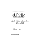
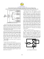
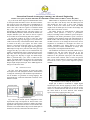
International Journal of Emerging Technology and Advanced Engineering
Website: www.ijetae.com (ISSN 2250-2459, ISO 9001:2008 Certified Journal, Volume 3, Issue 5, May 2013)
FPGA Based Wireless Control System for Robotic Applications
Khushbu Lalpuriya1, N. Ravi Prakash2, Naveen Rastogi3
1
VLSI and Embedded system design, Gujarat Technological University, Ahmedabad
2,3
Institute for Plasma Research, Gandhinagar
FPGA are used for time critical applications like real
time multi motor control in robotic arms, any multi-motor
precision application or any parallel processing application.
In order to accomplish more work, more logic circuits can
be added. FPGA get used ispecifically to do tasks a
microcontroller cannot do efficiently, such as highly
parallel or low latency operations, operating in multiple
clock domains, or doing custom logic at hardware speeds.
For these all reasons, FPGA is used to develop a control
system.
Spartan 3E FPGA board is used for system
implementation. Xc3s500E chip is used inside the board.
Kit contains on-board 50 MHz clock oscillator. For
experiment, two 9-pin RS-232 ports (DTE- and DCEstyle), 10 user-I/O pins, two-input SPI-based Analog-toDigital Converter (ADC) with programmable-gain preamplifier and 8 LEDs are used . More details about kit are
given in datasheet of Xilinx Spartan3E user manual [2].
To control robot remotely, wireless module ZigBee Pro
is used which works on ISM (Industrial, scientific and
Medical) band. It works on IEEE 802.15.4 standard. The
modules operate within the ISM 2.4 GHz frequency band.
Data rate to transmit the data is 250 kbps. It has indoor
range of 100 m and outdoor range of 1500 m which is
sufficient for robot control. More details of the module are
given in ZigBee manual [7]. Wireless module is interfaced
with the Spartan 3E FPGA board to control the
applications.
Work process flow and description of main modules are
given in the subsequent topics.
Abstract— Robotic applications are much more needed and
almost mandatory requirement in today's fast moving
industrial economy. In these circumstances the development
of Robotics is also taking up the speed with the help of various
technologies directly or indirectly suitable for robotic
applications. FPGA takes advantage over microcontroller due
to its hardware based parallel architecture. Motors are one of
the core part of the Robots and controlling them with FPGA is
little tricky. FPGA based wireless interface is used to remotely
control robotic applications. For that FPGA based PWM
signal generation method is used. Code can be made in such a
manner so that multiple parts (motors) can be controlled at a
time. The ports availability also provides flexibility to extend
the support for the number of motors or any Data acquisition
mechanism. A user friendly wireless interface is developed to
control robot remotely.
keywords— FPGA, multiple motors, parallel architecture,
PWM signal, robotic applications, wireless interfaces
I.
INTRODUCTION
In the fast growing world, real time controlling of any
robotic application is very important. The idea behind
developing the system is to make a single control system to
control multiple robotic applications simultaneously
because individual controller for every application is very
difficult to synchronize and development of logic for every
different application is also very time consuming. So the
system is to be developed such that it can control any
robotic application from remote area simultaneously in real
time. Communication interfaces are also to be developed
using which user can easily control any application
remotely. The whole control logic should be inside the
system, so the selection of controller is important. It
should be such that it contains large number of memory
storage inside it, so more numbers of logics can be added
within it.
For general applications, microcontroller is good enough
but critical applications would need real-time processing
that is time critical. In this case, FPGA would be the best
solution.
II.
P ROCESS FLOW
The main concept to build the system is to generate a
logic inside FPGA for proper selection of address signal
and data signal to control any kind of robots simultaneously
in robotic applications. Conceptual process flow is shown
in the figure below which contains the required basic
blocks. These blocks are generated in Verilog language to
load the logic in FPGA chip. The details of process flow is
described below:
335
International Journal of Emerging Technology and Advanced Engineering
Website: www.ijetae.com (ISSN 2250-2459, ISO 9001:2008 Certified Journal, Volume 3, Issue 5, May 2013)
B. WIRELESS INTERFACING VIA ZIGBEE MODULE
To interface FPGA with robotic applications, wireless
module ZigBee is used. Two modules are used in
experiment. From two, one is Coordinator which works as
transmitter and another is End device which works as
Receiver. Coordinator is attached with PC and End device
is attached with robotic application. Signal is transmitted to
robot from PC through coordinator ZigBee and received by
end device ZigBee. Robot is controlled as per the command
given from PC and logic developed inside the FPGA chip.
Every key pressing of PC represents particular ASCII
values which is transmitted through coordinator ZigBee
and it is wirelessly received end device ZigBee. End device
ZigBee sends the RS232 IC of FPGA board and it sends the
data to the FPGA chip through voltage translator. FPGA
has control logic of PWM signal generation module. So
whenever respectively key is sent through the PC, it will be
received by FPGA chip and will be sent to robot from the
digital I/O port. Any action/movement can be given to
robot by changing just the logic in the FPGA. Using this
concept, any robot can be controlled by FPGA through
wireless module.
Fig. 1. FPGA based wireless control system
For ease of use, the data is sent from PC. For that, Serial
interfacing is done which receives the data serially and
convert it to 8 bit binary numbers. Received 8 bit binary
numbers are stored in 8 bit latch. Here 8 bit latch is used to
store the desired received data for further use. From 8 bit
latched output, all bits are separated to access more number
of ports using less control signal.
From 8 bits of latch, 3 bits go into 3to8 decoder as a data
and 4th bit enables that decoder. Likewise, other 3 bits go
into the other 3to8 decoder as a data and 8th bit enables
that decoder. Output of the decoder is used to enable PWM
module for DC motor and other signals are the input
control signals to drive the DC motor. Other decoder's
output is used to enable the PWM module for Servo motor
and other signals are the input control signals. PWM
modules have separate logic for DC motors and Servo
motors. As per the user input, it can change the values of
respective signals.
Main modules of the control system are described in
next two sections.
C. PWM SIGNAL GENERATION MODULE
PWM is abbreviation of Pulse Width Modulation. It is
also known as the duty-cycle variation method. This
method is commonly used in speed control of motors.
"Pulse” is meant by an electromagnetic wave or
modulation. "Width Modulation” is meant by to adjust to or
keep in proper measure or proportion the width of the
pulse with respect to the frequency of the wave. The duty
cycle is defined as the percentage of digital ‘high’ to digital
‘low’ plus digital ‘high’ pulse-width during a PWM period.
50 MHz
PWM Period
control
20 ns
20 ms
A. SERIAL INTERFACING VIA RS232 PROTOCOL
Whenever any robot is to be remotely controlled through
the PC via wireless module then serial interfacing is very
important to communicate between them. In this
experiment, to control the robot through PC, RS232
interfacing is done. Spartan 3E FPGA kit has on-board
DTE and DCE DB9 port and RS232 voltage translator IC
in the kit. The data signal is transmitted from PC and
received by the FPGA chip using pin 2 and pin 3 of the
DB9 connector respectively.
Input Signal
PWM Duty
cycle Control
Duty Cycle
Up Counter
PWM Reg
PWM Signal
Fig. 2. Block diagram of PWM module
336
International Journal of Emerging Technology and Advanced Engineering
Website: www.ijetae.com (ISSN 2250-2459, ISO 9001:2008 Certified Journal, Volume 3, Issue 5, May 2013)
Fig. 2 shows the block diagram of PWM module which
is developed inside the FPGA to drive the motor with the
help of driver circuit. The architecture of the PWM part of
the module consists of two registers, an up counter and on
board clock. One of the two registers is to hold the PWM
duty cycle value, which is the ratio of ON/OFF time
determining the PWM waveform. The other register is to
hold the PWM period data, which controls the duration of a
complete ON/OFF cycle. The values in the two registers
are accessible via serial interfacing and can be updated.
Up and down counters are used to count only when
enabled and the Toggle flip flop toggles every time there is
a final count from any of the enabled counters. When a data
is loaded in the duty cycle register, the down counter
begins to count down from high value to zero. When it
crosses zero, the final count goes high, which toggles the
PWM output to high. Every time the final count goes high
it triggers the duty cycle value to be re-loaded and the Upcounter is enabled and the value is counted from zero to the
high value. Once the Up-counter reaches the final count, it
again triggers the flip-flop to toggle the PWM output.
When a particular duty cycle value is loaded into the
register, the PWM module will generate the corresponding
PWM signal and send it through the on-board General
Purpose Input Output (GPIO) pin. These PWM signals are
then given to drive the motor.
III.
PWM module is implemented inside the FPGA chip in
such a way that it can directly access the GPIO pins, and
thus through the driver card, it drives robot. H-bridge
circuit is used as DC motor driver circuit. The PWM
outputs from the GPIO pins are fed into the H-bridge and
then to drive a DC motor of robot.
The FPGA designs are implemented in Xilinx ISE
software, which provides a variety of performance
analyses, including resource utilization, speed, and power
consumption. The Xilinx performance report is based on
simulations of the hardware design. The interconnection of
PWM module with the FPGA chip has clock frequency of
50 MHz . However we can change the clock across various
frequencies in simulation to investigate the effects on
module performance. The timing analyzer of the ISE
software provides accurate information on delays from
various points, nets and pads inside the FPGA.
The simulation waveforms are measured with the help of
simulation tool and the results show that as per the
command given, signals can be properly selected and
addressed to the particular output port with 40ns delay.
Here for DC motor selection, when '1' and '0' are pressed
then it gives forward output to respective output channel.
Likewise for '0' and '1' , gives reverse output to respective
channel.
IMPLEMENTATION
We have used Xilinx Spartan 3E board and Xilinx
development tool ISE (Integrated Software Environment)
to design the control logic and conducted experimental test.
All the modules are generated in Verilog language. The
experimental test verified the functional correctness of the
hardware module.
Fig. 5. Simulation result for multiple DC motor control
Output port of FPGA is connected to Digital Signal
Oscilloscope before directly applying to motor. As shown
in the waveform first two channels are for one DC motor
which is in forward direction and last two are for second
DC motor which is in reverse direction. Here medium
speed is selected by applying 50% duty cycle.
Fig. 4. Experimental Set up
Fig. 4 shows the overall system configuration of the
experimental setup and Spartan 3E FPGA board is the
central piece with wireless end device module and robotic
application with required motor driver circuit attached. The
board has a XC3s500E FPGA chip on it The GPIO pins on
the board are directly connected to the FPGA device.
Fig. 6. Experimental waveform for DC motor logic
337
International Journal of Emerging Technology and Advanced Engineering
Website: www.ijetae.com (ISSN 2250-2459, ISO 9001:2008 Certified Journal, Volume 3, Issue 5, May 2013)
As shown in the first waveform, three servo motors are
controlled at the same angle and in the second waveform,
two motors are controlled at same angle and the third is at
different angle.
IV.
In this paper, FPGA based real time control system is
developed for wirelessly control any type of motors in
robotic applications. Addressing of control signals and
sending data to particular signal are implemented in this
paper. Hardware module is developed to generate PWM
output pulses, which are the basic building blocks to drive
robots. With the use of communication interfaces provided,
all modules can be easily accessible. ZigBee and FPGA
interfacing was also successfully developed. Functional
verifications are done by applying the logic on the robotic
applications. This work was the prototype of a big system.
By applied logic, total 16 motors can be controlled but by
taking advantage of FPGA, more number of logics can be
added into the developed control system.
Fig. 7. Experimental waveform for DC motor control
As shown in the waveform, two DC motors are
simultaneously driven from a applied logic in FPGA. Here
logic is tested by applying different speed controls.
Module is tested with robotic application. Module is
tested with DC motor to test the control of the speed and
direction. From experiment, the speed of the motor is
varied as per the command given from the PC and the
direction is also controlled. The precise control of DC
motor can be checked by taking feedback from the encoder
attached on the wheel of the DC motor.
Module is tested with the servo motor to test the angle
control. From experiment, the angle of the motor is varied
as per the command given from the PC and the direction is
also controlled. Angles of the robotic application with servo
motors is tested as shown below:
Acknowledgment
This work is carried out in Institute for Plasma Research
as a part of Dissertation work of Master of Engineering
under guidance of Mr. N. Ravi Prakash. I am very thankful
to Institute for Plasma Research for giving me opportunity
to work.
Table 1
Experimental servo angles
Angle to be controlled
0°
45°
90°
135°
180°
CONCLUSION
Required PWM signal
1 ms
1.25 ms
1.50 ms
1.75 ms
2.00 ms
REFERENCES
[1]
[2]
[3]
[4]
[5]
[6]
[7]
Fig. 8. Experimental waveforms for servo motor control
338
Samir Palnitkar, "Verilog HDL, A guide to digital design and
synthesis", SunSoft press 1996
Xilinx, "Spartan-3E FPGA Starter Kit Board User Guide", UG230
(v1.2) January 20, 2011
Narashiman Chakravarthy, Jizhong Xiao, "FPGA-based Control
System for Miniature Robots" IEEE/RSJ International conference on
Intelligent Robots and systems, October 9,2006
National Instruments, "Pulse Width Modulation using NI-DAQmx
and LabVIEW", May10, 2010
Tim Bennett and Vincent Rosa, "Speed control of DC motor using
Pulse width modulation", Data Acquisition and Control Systems,
Spring 2009
"Servo motors control & Arduino", Future Electronics
MaxStream, Inc. "XBee™/XBee-PRO™ OEM RF Modules",
October,2010


![2008 [DAMN SMALL NAS]](http://vs1.manualzilla.com/store/data/005757702_2-ad0d2f1082977ee9ed587e807bbc0127-150x150.png)