1
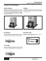
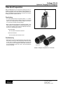
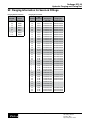
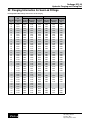
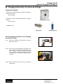
Parflange ECO 25 Hydraulic Flanging and Flaring Tool Bulletin 4390 - ECO25 June 2015 Parflange ECO 25 Hydraulic Flanging and Flaring Tool WARNING FAILURE OR IMPROPER SELECTION OR IMPROPER USE OF THE PRODUCTS AND/OR SYSTEMS DESCRIBED HEREIN OR RELATED ITEMS CAN CAUSE DEATH, PERSONAL INJURY AND PROPERTY DAMAGE. This document and other information from Parker Hannifin Corporation, its subsidiaries and authorized distributors provide product and/or system options for further investigation by users having technical expertise. It is important that you analyze all aspects of your application and review the information concerning the product or system in the current product catalog. Due to the variety of operating conditions and applications for these products or systems, the user, through its own analysis and testing, is solely responsible for making the final selection of the products and systems and assuring that all performance, safety and warning requirements of the application are met. The products described herein, including without limitation, product features, specifications, designs, availability and pricing, are subject to change by Parker Hannifin Corporation and its subsidiaries at any time without notice. Offer of Sale The items described in this document are hereby offered for sale by Parker Hannifin Corporation, its subsidiaries or its authorized distributors. This offer and its acceptance are governed by the provisions stated in the “Offer of Sale.” 2 Parker Hannifin Corporation Tube Fittings Division Columbus, Ohio http://www.parker.com/tfd Parflange ECO 25 Hydraulic Flanging and Flaring Tool Table of Contents Features and Advantages....................................................................................4 ECO 25 Specifications.........................................................................................5 Setup Instructions................................................................................................5 Tube End Preparation..........................................................................................6 90˚ Flanging Information for Seal-Lok Fittings............................................ 7-13 37˚ Flaring Information for Triple-Lok Fittings........................................... 14-20 Component Parts Breakdown..................................................................... 21-27 ECO 25 Guide Assembly...............................................................................21 ECO 25 Flare/Flange Head Assembly..........................................................23 ECO 25 Die Holder Assembly.......................................................................25 ECO 25 Motor Assembly...............................................................................27 Offer of Sale........................................................................................................28 3 Parker Hannifin Corporation Tube Fittings Division Columbus, Ohio http://www.parker.com/tfd Parflange ECO 25 Hydraulic Flanging and Flaring Tool Features and Advantages Easy to Operate Portable The ECO 25 is capable of flanging or flaring steel and stainless tubing with a few simple operations. And since each die has flanging tooling on one side and flaring tooling on the other, you only need one die to perform both functions. In addition, because of its adjustable tube stop, the ECO 25 does not require a different die for each wall thickness of tubing – just one die for each tube outside diameter. The ECO 25 has handles on three sides of the machine, making moving it around the workplace an easy task. It can either be set on its rubber feet or, for a more permanent location, bolted to a work bench or cart. 90˚ Flanging Hydraulic Pump The ECO 25 is capable of completing 90° flanges on steel and stainless steel tubing from ¼” through 1½” outside diameters for use with O-ring Face Seal tube fittings, such as Parker Seal-Lok™. The ECO 25 is easily operated using a hand hydraulic pump, allowing it to be utilized virtually anywhere. Hand Pump 37˚ Flaring The ECO 25 is capable of completing 37° flares on steel and stainless steel tubing from ¼” through 1½” outside diameters for use with JIC 37˚ flared tube fittings, such as Parker Triple-Lok®. 4 Parker Hannifin Corporation Tube Fittings Division Columbus, Ohio http://www.parker.com/tfd Parflange ECO 25 Hydraulic Flanging and Flaring Tool ECO 25 Specifications Height 20.5 in. (520 mm) Width 15 in. (381 mm) Depth 20.5 in. (520 mm) Weight 190 lbs. (86.4 kg) Electrical Requirements 110 Volt, 1 phase, 60Hz/20A Motor 1.5 HP Maximum Pump Flow 20 in.3/min. Max. # Flares/Flanges per day 50 Capacity (90° Flanging) Steel Tubing 1 1/2" O.D. x .120 Wall (38mm O.D. x 4mm Wall) Stainless Steel Tubing 1 1/2" O.D. x .120 Wall (38mm O.D. x 4mm Wall) Capacity (37° Flaring) Steel Tubing 1 1/2" O.D. x .120 Wall (38mm O.D. x 4mm Wall) Stainless Steel Tubing 1 1/2" O.D. x .120 Wall (38mm O.D. x 4mm Wall) Setup Instructions Step 1: ECO 25 Adapter Step 5: Hose Conversion Adapters Ensure the ECO 25 Adapter (part number 6 F5OLO-S) is properly installed into the SAE straight thread port in the rear of the ECO 25 cylinder. Install Hose Conversion Adapter #1 (part number 6 G6L-S) onto the 1/4" male NPT threaded end (smaller end) of the Hose Assembly (part number 910133) using a pipe thread sealant. Then, install Hose Conversion Adapter #2 (part number 6-6 G6L-S) onto the 3/8" male NPT end (larger end) of the Hose Assembly using a pipe thread sealant.. Step 2: Hydraulic Pump Tee Install the Hydraulic Pump Adapter (part number 6-6 FLO-S) into the NPT pipe thread port in the rear of the hand-hydraulic pump with a pipe thread sealant. Assemble the swivel end of the Hydraulic Pump Tee (part number 6 R6LO-S) to the Hydraulic Pump Adapter. Make sure the branch end of the Tee is oriented upward. Step 6: Hose to Pump Tee Assembly Assemble the swivel end of the Hose Conversion Adapter #2 (part number 6-6 G6L-S) to the remaining end of the Hydraulic Pump Tee (part number 6 R6LO-S). Step 3: Pressure Gauge Adapter Step 7: Hose to ECO 25 Assembly Assemble the Pressure Gauge Adapter (part number 6 G6L-S) onto the NPT Pipe Thread end of the pressure gauge (part number 900044) with a pipe thread sealant. Assemble the swivel end of Hose Conversion Adapter #1 (part number 6 G6L-S) to the ECO 25 Adapter (part number 6 F5OLO-S). Step 4: Pressure Gauge Step 8: Check for Leaks Assemble the Pressure Gauge and Adapter assembly onto the Assuring all connections are properly tightened, operate the branch end of the Hydraulic Pump Tee (part number 6 R6LO-S). hydraulic pump and check for leaks. Make sure to orient the front of the gauge toward the front of the ECO 25 so it may be seen during operation. 5 Parker Hannifin Corporation Tube Fittings Division Columbus, Ohio http://www.parker.com/tfd Parflange ECO 25 Hydraulic Flanging and Flaring Tool Tube End Preparation Tube end preparation is one of the most critical processes in obtaining an optimum seal of a flanged or flared tube end connection. Regardless of the tube material, similar guidelines for tube cut-off, deburring, and cleanliness can help assure the tube to fitting connection remains leak free. Tube Cutting • It is critical that the tube be cut squarely within +/- 1° in order to assure the proper tube to fitting connection. A tube end which is not cut squarely may result in a flange or flare which is not circular, potentially causing leakage. • W hen cutting tube in preparation for flanging or flaring, a saw which utilizes a toothed blade is recommended. This type of tool will assure that the tube end is not hardened from excessive heat or cold working of material. Recommended Low speed Circular Saw, Hacksaw Not Recommended Rotary Tube Cutter, Abrasive Saw Tube Deburring • D eburring the inside and outside diameter of the tube end is necessary to assure the tube fits properly inside the flange or flare sleeve. In addition, proper deburring of the tube end is necessary to form a flanged or flared tube end which is free of imperfections that may create a leak path between the tube and fitting. Improper Cut Proper Cut Samples of improper and proper cuts on steel tube 6 Parker Hannifin Corporation Tube Fittings Division Columbus, Ohio http://www.parker.com/tfd Parflange ECO 25 Hydraulic Flanging and Flaring Tool 90˚ Flanging Information for Seal-Lok Fittings Flanging Die Set, Inch Sizes Tube O.D. (in.) 1/4 3/8 1/2 5/8 3/4 1 1 1/4 1 1/2 Die Set Part Number M2504 M2506 M2508 M2510 M2512 M2516 M2520 M2524 Flanging Pin, Inch Sizes Tube O.D. (in.) 1/4 1/4 1/4 3/8 3/8 3/8 1/2 1/2 1/2 1/2 1/2 5/8 5/8 5/8 5/8 5/8 3/4 3/4 3/4 3/4 3/4 3/4 1 1 1 1 1 1 1 1/4 1 1/4 1 1/4 1 1/4 1 1/4 1 1/4 1 1/2 1 1/2 1 1/2 1 1/2 1 1/2 Wall Thickness (in.) 0.028 0.035 0.049 0.035 0.049 0.065 0.035 0.049 0.065 0.083 0.095 0.049 0.065 0.083 0.095 0.120 0.049 0.065 0.083 0.095 0.109 0.120 0.065 0.083 0.095 0.109 0.120 0.134 0.065 0.083 0.095 0.109 0.120 0.134 0.065 0.083 0.095 0.109 0.120 Flanging Pin Steel Tube B4004X028180 B4004X035180 B4004X049180 B4006X035180 B4006X049180 B4006X065180 B4008X035180 B4008X049180 B4008X065180 B4008X083180 B4008X095181 B4010X049180 B4010X065180 B4010X083180 B4010X095180 B4010X120180 B4012X049180 B4012X065180 B4012X083180 B4012X095180 B4012X109180 B4012X120180 B4016X065180 B4016X083180 B4016X095180 B4016X109180 B4016X120180 B4016X134180 B4020X065180 B4020X083180 B4020X095180 B4020X109180 B4020X120180 B4020X134180 B4024X065180 B4024X083180 B4024X095180 B4024X109180 B4024X120180 7 Flanging Pin Stainless Tube B4004X035180SS B4004X049180SS B4006X035180SS B4006X049180SS B4006X065180SS B4008X035180SS B4008X049180SS B4008X065180SS B4008X083180SS B4008X095180SS B4010X049180SS B4010X065180SS B4010X083180SS B4010X095180SS B4012X049180SS B4012X065180SS B4012X083180SS B4012X095180SS B4012X109180SS B4012X120180SS B4016X065180SS B4016X083180SS B4016X095180SS B4016X109180SS B4016X120180SS B4020X083180SS B4020X095180SS B4020X109180SS B4020X120180SS B4024X095180SS B4024X109180SS B4024X120180SS Parker Hannifin Corporation Tube Fittings Division Columbus, Ohio http://www.parker.com/tfd Parflange ECO 25 Hydraulic Flanging and Flaring Tool 90˚ Flanging Information for Seal-Lok Fittings Parflange ECO 25 Dial Settings and Pressures for 90˚ Flanging Steel Tube Tube O.D. (in.) 1/4 1/4 1/4 3/8 3/8 3/8 1/2 1/2 1/2 1/2 1/2 5/8 5/8 5/8 5/8 5/8 3/4 3/4 3/4 3/4 3/4 3/4 1 1 1 1 1 1 1 1/4 1 1/4 1 1/4 1 1/4 1 1/4 1 1/4 1 1/2 1 1/2 1 1/2 1 1/2 1 1/2 Wall Thickness (in.) 0.028 0.035 0.049 0.035 0.049 0.065 0.035 0.049 0.065 0.083 0.095 0.049 0.065 0.083 0.095 0.120 0.049 0.065 0.083 0.095 0.109 0.120 0.065 0.083 0.095 0.109 0.120 0.134 0.065 0.083 0.095 0.109 0.120 0.134 0.065 0.083 0.095 0.109 0.120 Tube Stop Setting 0088 0086 0077 0095 0089 0082 0099 0094 0093 0088 0079 0088 0083 0075 0071 0068 0081 0075 0075 0064 0059 0055 0074 0072 0064 0059 0055 0050 0081 0075 0072 0067 0064 0059 0070 0065 0061 0056 0053 Head Stop Setting 0199 0196 0198 0200 0202 0201 0203 0195 0204 0204 0204 0195 0200 0199 0197 0208 0197 0200 0202 0200 0199 0198 0196 0198 0199 0201 0200 0201 0194 0199 0199 0196 0199 0200 0192 0196 0197 0194 0198 Stainless Steel Tube Flanging Pressure (psi) 1000 1000 1500 1000 1600 2000 1000 1500 1600 2000 2200 1600 2000 2600 2000 4800 1500 2000 3000 3000 3000 3000 3000 3000 3200 3400 4000 4500 3600 4000 4000 4000 4800 5000 2000 3600 4600 4600 5000 Tube Stop Setting 0086 0075 0082 0084 0082 0098 0094 0088 0078 0073 0078 0078 0072 0066 0077 0067 0064 0059 0045 0050 0065 0063 0064 0047 0045 0063 0062 0058 0045 0031 0044 0038 8 Head Stop Setting 0201 0208 0205 0206 0206 0202 0198 0205 0201 0200 0198 0201 0208 0206 0202 0206 0200 0203 0203 0203 0200 0204 0199 0201 0201 0203 0202 0201 0198 0190 0192 0187 Flanging Pressure (psi) 2000 3000 2500 2500 3000 2000 3000 3500 3600 3600 3000 3000 5000 5000 4600 5600 5000 5000 6000 6500 4500 5000 5500 6500 6500 6500 6000 6000 6500 6500 6500 6000 Parker Hannifin Corporation Tube Fittings Division Columbus, Ohio http://www.parker.com/tfd Parflange ECO 25 Hydraulic Flanging and Flaring Tool 90˚ Flanging Information for Seal-Lok Fittings Components Required • D ual-Function Flare/Flange Die Set (contains tooling for both Flanging and Flaring) See chart page 7 • F langing Pin specific to Tube O.D., Wall Thickness, and Tube Material Dual Function Die Set See chart page 7 • LB-2000 Lubricant Flanging Pin LB-2000 Lubricant ECO 25 Operating Instructions for 90˚ Flanging for Seal-Lok FIttings Step 1:Measure the tube O.D. and wall thickness for proper die and pin selection. Step 2:Select the die set and flanging pin matching the tube O.D., wall thickness and material of your tube from the charts on page 7. The die set is stamped with the tube O.D. and the pin is stamped with both the tube O.D. and wall thickness (and material if flanging stainless steel tube). Step 3:Open the swing arm to expose die cavity and main spindle head. 9 Parker Hannifin Corporation Tube Fittings Division Columbus, Ohio http://www.parker.com/tfd Parflange ECO 25 Hydraulic Flanging and Flaring Tool 90˚ Flanging Information for Seal-Lok Fittings Step 4:Raise the tube stop and install the flanging pin into the main spindle head of the machine. Be sure to lower the tube stop to its original position after inserting the pin. Step 5:Using the LB-2000 lubricant, adequately lubricate the flanging pin as well as the inside diameter of the tube end. It is very important to lubricate the Flanging Pin and Inside Diameter of the tube end prior to each flanging operation. Step 6:Insert the bottom half of the die set (either die half can be used) into the die cavity of the machine using the keyways on either side to secure the die. Ensure that the 90° Flange side of the die half is facing toward the main spindle head of the machine (away from the operator). Step 7:Place a Parflange mechanical sleeve (part number TPL) onto the end of the tube with the widest part of the sleeve facing the end of the tube you intend to flange. Place the sleeve and tube assembly into the bottom half of the die set, ensuring the Parflange sleeve is placed into the corresponding cavity in the die half. Step 8:Insert the top half of the die set into the die cavity on top of the other half, also ensuring that the 90° Flange side of the die half is facing toward the main spindle head of the machine. Step 9:Set Tube Stop adjustment dial to recommended value for flanging the O.D., wall thickness and material of the tubing you are using (See Chart on page 8). Dial settings are recommendations only and may require adjustment to obtain desired results. 10 Parker Hannifin Corporation Tube Fittings Division Columbus, Ohio http://www.parker.com/tfd Parflange ECO 25 Hydraulic Flanging and Flaring Tool 90˚ Flanging Information for Seal-Lok Fittings Step 10:Set Head Stop adjustment dial to recommended value for flanging the O.D., wall thickness and material of the tubing you are using (See Chart on page 8). Dial settings are recommendations only and may require adjustment to obtain desired results. Step 11:Close swing arm against shoulder bolt. Step 12:While keeping tube end against tube stop, rotate clamp vise arm clockwise and securely clamp tube in die set. Be sure to properly support long tubes during the clamping and flanging process. Step 13:Obtain the recommended flanging pressure for the O.D., wall thickness, and tube material you are using from the chart on page 8. Step 14:Press and release green start button on front of machine to start rotation of main spindle head. If head does not rotate upon activation of motor, check electrical connections and retry. Be sure to use an electrical outlet with 110V/20A power. Step 15:Ensure the tube is held in position and slowly actuate the hydraulic hand pump. The flanging pin will come forward and the tube stop will automatically rise up and away from the tube. The pressure gauge will show a rapid rise in pressure as the pin engages the tube end and flanges the tube. 11 Parker Hannifin Corporation Tube Fittings Division Columbus, Ohio http://www.parker.com/tfd Parflange ECO 25 Hydraulic Flanging and Flaring Tool 90˚ Flanging Information for Seal-Lok Fittings Step 16:When the pressure gauge reaches the recommended flanging pressure from Step 13, de-energize the hydraulic power supply. This will allow the flanging pin and spindle head to retract to their original position. Step 17:Press the red stop button on the front of the machine to stop rotation of the main spindle head. Step 18:Rotate clamp vise handle counter-clockwise to loosen clamp from die set and tube and open swing arm to expose die halves. Step 19:Remove the top half of the die set from the die cavity and set aside. Step 20:Remove flanged tube from bottom half of die. 12 Parker Hannifin Corporation Tube Fittings Division Columbus, Ohio http://www.parker.com/tfd Parflange ECO 25 Hydraulic Flanging and Flaring Tool 90˚ Flanging Information for Seal-Lok Fittings Step 21: I nspect flange to ensure proper surface finish. Measure the flange diameter and compare to values in chart below. Adjusting the ECO 25 to compensate for over/undersized flange diameters Flange Diameter If the flange diameter of your ECO 25 tube assembly is not within the diameter specifications listed, please complete the following steps: • F irst, check to make sure that the correct flanging pin and die set are being used for the outside diameter, wall thickness, and material tubing you are using. Keep in mind that each Die Set can be used with every wall thickness of that size tubing and also with both carbon and stainless steel tubing. However, the flanging pins are specific to the outside diameter, wall thickness, and material of the tubing. • O nce the tooling and tubing have been verified, the correct method of increasing or decreasing the diameter of the tube flange is to alter the Head Stop adjustment dial (do not change the Tube Stop adjustment dial setting). • T o increase the diameter of a tube flange, adjust the Head Stop adjustment dial Clockwise (dial setting number will increase) a small amount and repeat the flanging process. If the desired result is not achieved, repeat adjustment process as needed until the proper sized flange is made. Inch Tube O.D. (in.) 1/4 3/8 1/2 5/8 3/4 1 1-1/4 1-1/2 Metric Tube O.D. (mm) 6 10 12 14, 15, 16 18, 20 22, 25 28, 30, 32 38 Flange Diameter (in.) .478 / .502 .594 / .620 .719 / .745 .875 / .923 1.048 / 1.097 1.298 / 1.347 1.549 / 1.597 1.861 / 1.910 90˚ Flange dimensions • T o decrease the diameter of a tube flange, adjust the Head Stop adjustment dial Counter Clockwise (dial setting number will decrease) a small amount and repeat the flanging process. If the desired result is not achieved, repeat adjustment process as needed until the proper sized flange is made. 13 Parker Hannifin Corporation Tube Fittings Division Columbus, Ohio http://www.parker.com/tfd Parflange ECO 25 Hydraulic Flanging and Flaring Tool 37˚ Flaring Information for Triple-Lok Fittings Flaring Die Sets, Inch Sizes Fitting Dash Size 4 6 8 10 12 16 20 24 Tube O.D. (in.) 1/4 3/8 1/2 5/8 3/4 1 1 1/4 1 1/2 Die Set Part Number M2504 M2506 M2508 M2510 M2512 M2516 M2520 M2524 Flaring Pins, Inch Sizes Tube O.D. (in.) 1/4 1/4 1/4 3/8 3/8 3/8 1/2 1/2 1/2 1/2 5/8 5/8 5/8 5/8 3/4 3/4 3/4 3/4 3/4 1 1 1 1 1 1 1/4 1 1/4 1 1/4 1 1/4 1 1/4 1 1/2 1 1/2 1 1/2 1 1/2 1 1/2 Wall Thickness (in.) 0.028 0.035 0.049 0.035 0.049 0.065 0.035 0.049 0.065 0.083 0.049 0.065 0.083 0.095 0.049 0.065 0.083 0.095 0.109 0.065 0.083 0.095 0.109 0.120 0.065 0.083 0.095 0.109 0.120 0.065 0.083 0.095 0.109 0.120 Flaring Pin Part Number B4004X028074 B4004X035074 B4004X049074 B4006X035074 B4006X049074 B4006X065074 B4008X035074 B4008X049074 B4008X065074 B4008X083074 B4010X049074 B4010X065074 B4010X083074 B4010X095074 B4012X049074 B4012X065074 B4012X083074 B4012X095074 B4012X109074 B4016X065074 B4016X083074 B4016X095074 B4016X109074 B4016X120074 B4020X065074 B4020X083074 B4020X095074 B4020X109074 B4020X120074 B4024X065074 B4024X083074 B4024X095074 B4024X109074 B4024X120074 Note: T ooling suitable for 37˚ flaring of steel and stainless steel tube materials. One die covers each tube O.D., but a different pin is required for each tube wall thickness. 14 Parker Hannifin Corporation Tube Fittings Division Columbus, Ohio http://www.parker.com/tfd Parflange ECO 25 Hydraulic Flanging and Flaring Tool 37˚ Flaring Information for Triple-Lok Fittings Parflange ECO 25 Dial Settings and Pressures for 37˚ Flaring Tube O.D. (in.) 1/4 1/4 1/4 3/8 3/8 3/8 1/2 1/2 1/2 1/2 5/8 5/8 5/8 5/8 3/4 3/4 3/4 3/4 3/4 1 1 1 1 1 1 1/4 1 1/4 1 1/4 1 1/4 1 1/4 1 1/2 1 1/2 1 1/2 1 1/2 1 1/2 Wall Thickness (in.) 0.028 0.035 0.049 0.035 0.049 0.065 0.035 0.049 0.065 0.083 0.049 0.065 0.083 0.095 0.049 0.065 0.083 0.095 0.109 0.065 0.083 0.095 0.109 0.120 0.065 0.083 0.095 0.109 0.120 0.065 0.083 0.095 0.109 0.120 Steel Tube Tube Stop Setting 0150 0150 0150 0150 0150 0150 0150 0150 0150 0150 0150 0150 0150 0150 0150 0150 0150 0150 0150 0150 0150 0150 0150 0150 0150 0150 0150 0150 0150 0150 0150 0150 0150 0150 Head Stop Setting 0275 0275 0275 0275 0275 0275 0275 0275 0275 0275 0275 0275 0275 0275 0275 0275 0275 0275 0275 0275 0275 0275 0275 0275 0275 0275 0275 0275 0275 0275 0275 0275 0275 0275 Flaring Pressure (psi) 1000 1000 1000 1000 1000 1000 1000 1000 1000 1000 1000 1500 2000 2000 1000 1500 2000 2000 2000 1500 1500 1500 2000 3000 2500 2500 3000 3000 3500 2000 2000 2000 2500 2500 Stainless Steel Tube Flaring Tube Stop Head Stop Pressure Setting Setting (psi) 0150 0275 1000 0150 0275 1000 0150 0275 1500 0150 0275 1000 0150 0275 1500 0150 0275 1500 0150 0275 1500 0150 0275 1500 0150 0275 1500 0150 0275 1500 0150 0275 1500 0150 0275 2000 0150 0275 2000 0150 0275 2500 0150 0275 1500 0150 0275 2000 0150 0275 2000 0150 0275 2500 0150 0275 2500 0150 0275 2000 0150 0275 2000 0150 0275 2500 0150 0275 3500 0150 0275 4000 0150 0275 2500 0150 0275 3000 0150 0275 3500 0150 0275 3500 0150 0275 3500 0150 0275 2000 0150 0275 2000 0150 0275 2500 0150 0275 3000 0150 0275 3000 15 Parker Hannifin Corporation Tube Fittings Division Columbus, Ohio http://www.parker.com/tfd Parflange ECO 25 Hydraulic Flanging and Flaring Tool 37˚ Flaring Information for Triple-Lok Fittings Components Required • D ual-Function Flare/Flange Die Set (contains tooling for both Flanging and Flaring) See chart page 14 • Flaring Pin specific to Tube O.D. and Wall Thickness Dual Function Die Set See chart page 14 • LB-2000 Lubricant Flaring Pin LB-2000 Lubricant ECO 25 Operating Instructions for 37˚ Flaring for Triple-Lok FIttings Step 1:Measure the tube O.D. and wall thickness for proper die and pin selection. Step 2:Select the die set and flaring pin matching the tube O.D. and wall thickness of your tube from the chart on page 7. The die set is stamped with the tube O.D. and the pin is stamped with both the tube O.D. and wall thickness. Step 3:Open the swing arm to expose die cavity and main spindle head. 16 Parker Hannifin Corporation Tube Fittings Division Columbus, Ohio http://www.parker.com/tfd Parflange ECO 25 Hydraulic Flanging and Flaring Tool 37˚ Flaring Information for Triple-Lok Fittings Step 4:Raise the tube stop and install the flaring pin into the main spindle head of the machine. Be sure to lower the tube stop to its original position after inserting the pin. Step 5:Using the LB-2000 lubricant, adequately lubricate the flaring pin as well as the inside diameter of the tube end. It is very important to lubricate the Flaring Pin and Inside Diameter of the tube end prior to each flaring operation. Step 6:Insert the bottom half of the die set (either die half can be used) into the die cavity of the machine using the keyways on either side to secure the die. Ensure that the 37° Flare side of the die half is facing toward the main spindle head of the machine (away from the operator). Step 7:Insert the top half of the die set into the die cavity on top of the other half, also ensuring that the 37° Flare side of the die half is facing toward the main spindle head of the machine. Step 8:Rotate the Tube Stop adjustment dial clockwise until it cannot be adjusted any further (dial should read approximately 0150). At this point, the tube stop should be in contact with the back side of the die set, but please ensure it is not pressing against the die set too tightly, as this can damage the machine. The aim is to line up the tube end flush with the back side of the die set. This process will be the same for every size and wall thickness of tubing used. Step 9:Rotate the Head Stop adjustment dial clockwise until it cannot be adjusted any further (dial should read approximately 0275 but it may be slightly higher or lower). The aim is to get the head stop out of the way of the spindle head travel, as it is not necessary for the flaring process. This process will be the same for every size and wall thickness of tubing used. 17 Parker Hannifin Corporation Tube Fittings Division Columbus, Ohio http://www.parker.com/tfd Parflange ECO 25 Hydraulic Flanging and Flaring Tool 37˚ Flaring Information for Triple-Lok Fittings Step 10:Insert the tube through the die set until it touches the tube stop. You may have to raise the upper die half slightly to allow the tube to fully insert through the die set. Step 11:Close swing arm against shoulder bolt. Step 12:While keeping the tube end against the tube stop, rotate clamp vise arm clockwise and securely clamp tube in die set. Be sure to properly support long tubes during the clamping and flaring process. Step 13:Obtain the recommended flaring pressure for the O.D., wall thickness, and tube material you are using from the chart on page 15. Step 14:Press and release green start button on front of machine to start rotation of main spindle head. If head does not rotate upon activation of motor, check electrical connections and retry. Be sure to use an electrical socket with 110V/20A power. Step 15:Ensure the tube is held in position and energize the hydraulic power supply. The flaring pin will come forward and the tube stop will automatically rise up and away from the tube end. The pressure gauge will show a rapid rise as the pin engages the tube end and flares the tube. 18 Parker Hannifin Corporation Tube Fittings Division Columbus, Ohio http://www.parker.com/tfd Parflange ECO 25 Hydraulic Flanging and Flaring Tool 37˚ Flaring Information for Triple-Lok Fittings Step 16:When the pressure gauge reaches the recommended flaring pressure from Step 13, de-energize the hydraulic power supply. This will allow the flaring pin and spindle head to retract to their original position. Step 17:Press the red stop button on the front of the machine to stop rotation of the main spindle head. Step 18:Rotate clamp vise handle counter-clockwise to loosen clamp from die set and tube and open swing arm to expose die halves. Step 19:Remove the top half of the die set from the die cavity and set aside. Step 20:Remove flared tube from bottom half of die set 19 Parker Hannifin Corporation Tube Fittings Division Columbus, Ohio http://www.parker.com/tfd Parflange ECO 25 Hydraulic Flanging and Flaring Tool 37˚ Flaring Information for Triple-Lok Fittings Step 21:Inspect the flare to ensure proper surface finish. Measure the flare diameter and compare to values in chart below. Adjusting the ECO 25 to compensate for over/undersized flare diameters If the flare diameter of your ECO 25 tube assembly is not within the diameter specifications listed, please complete the following steps: • F irst, check to make sure that the correct flaring pin and die set are being used for the outside diameter, wall thickness, and material tubing you are using. Keep in mind that each Die Set can be used with every wall thickness of that size tubing and also with both carbon and stainless steel tubing. However, the flaring pins are specific to the outside diameter and wall thickness of the tubing. Inch Tube O.D. (in.) 1/4 5/16 3/8 1/2 5/8 3/4 1 1 1/4 • O nce the tooling and tubing have been verified, the correct method of increasing or decreasing the diameter of the tube flare is to alter the flaring pressure used during the flaring process. • T o increase the diameter of a tube flare, repeat the flaring process as before, but utilize a slightly higher flaring pressure than noted in the charge on page 15. Continue this process until the flare diameter is within the specifications listed to the right. 1 1/2 Metric 37° Flare Tube O.D. Diameter ØA (mm) (in.) 6 .340/.360 8 .400/.430 10 .460/.490 12 .630/.660 15 & 16 .760/.790 18 & 20 .920/.950 25 1.170/1.200 30 & 32 1.480/1.510 38 1.700/1.730 37° Flare Dimensions • T o decrease the diameter of a tube flare, repeat the flaring process as before, but utilize a slightly lower flaring pressure than noted in the chart on page 15. Continue this process until the flare diameter is within the specifications listed to the right. 20 Parker Hannifin Corporation Tube Fittings Division Columbus, Ohio http://www.parker.com/tfd 59 8 46 35 56 16 78 65 10 1 57 37 11 45 44 36 50 12 Component Parts Breakdown - ECO 25 Guide Assembly 9 20 39 40 34 6 19 21 Parflange ECO 25 Hydraulic Flanging and Flaring Tool 21 Parker Hannifin Corporation Tube Fittings Division Columbus, Ohio http://www.parker.com/tfd Qty. 1 2 1 1 1 1 1 1 4 4 1 8 4 1 2 2 1 6 1 1 1 1 1 1 1 3 Item 1 6 8 9 10 19 20 21 39 40 46 56 57 65 78 16 34 35 36 37 44 45 12 50 11 59 SK112111JW0501 SK112111JW06 SK072012JW00 BRONZE BUSHING GUIDE RAIL SK080212RH00 GUIDE REAR-FRONT BOLT GUIDE RAIL BOLTS TUBE STOP FORCE ROD BOLT BUMPER FOOT TUBE STOP FORCE ROD SET SCREW HEAD STOP COTTER PIN BUSHING SCREW SK080312JW00 SK080212JW00 PISTON DOWEL PIN PISTON SCREW SK0328201202JW SK0410201200JW SK081212EL00 GUIDE DOWEL Part Number SK112111JW01_02 RETRACTING SPRING SK112111JW03 SK112111JW04 SK112111JW02 5/16" -18 X 2.125" HEIGHT 8-32 X 1/8" LG ALLOY STEEL SET SCREW 1/16" DIA. 1" LG. STANDARD STEEL COTTER PIN 10-32 X 7/16" LG BUTTON HEAD SOCKET CAP SCREW PISTON CAP PISTON SHAFT 1/8" X 3/8" STEEL DOWEL PIN 1/4"-20 X 3/4 LG. BLACK OXIDE ALLOY STEEL SOCKET HEAD CAP SCREW PISTON CYLINDER HYDRAULIC CYLINDER PISTON SPRING PISTON END PLUG 3/8" DIA. X 7/8" LG. STEEL DOWEL HEAD STOP HEAD STOP ARM THREADED BAR - HEAD STOP SAE 863 BRONZE SLEEVE BEARING FOR 1 1/2" SHAFT DIAMETER, 1 3/4" OD, 1" LENGTH 1 1/2" DIAMETER 12 1/2" LONG DIE POST 1/2"-20 UNF-2B THREAD 1" DEPTH DRILLED ON CENTER BOTH ENDS TUBE STOP FORCE ROD 3/8"-16 X 1 3/4" BLACK OXIDE ALLOY STEEL SOCKET CAP SCREW GRADE 8 1/2"-20 X 1 1/2" BLACK OXIDE ALLOY STEEL SOCKET CAP SCREW GRADE 8 Description BACK PLATE 6" LENGTH, 1 15/16" OD, .192" WIRE DIAMETER, SPRING TEMPERED STEEL COMPRESSION SPRING GUIDE CENTER GUIDE FRONT GUIDE REAR Component Parts Breakdown - ECO 25 Guide Assembly Parts List Parflange ECO 25 Hydraulic Flanging and Flaring Tool 22 Parker Hannifin Corporation Tube Fittings Division Columbus, Ohio http://www.parker.com/tfd 30 25 28 29 ECO 25 Flare/Flange Head Assembly 7 26 24 27 43 13 33 41 31 Parflange ECO 25 Hydraulic Flanging and Flaring Tool 23 Parker Hannifin Corporation Tube Fittings Division Columbus, Ohio http://www.parker.com/tfd Item 7 13 24 25 26 27 28 29 30 31 33 41 43 Qty. 1 1 1 2 1 1 1 1 3 1 1 1 1 Part Number SK112311JW0102 LARGE PULLEY KEY GUIDE BEARING SKF 51206 BEARING SKF 6012-2RS1 BEARING INA BK3026 BEARING INA HK5022 BEARING TORRINGTON FNT-4060 THRUST WASHER TORRINGTON FTRA-4060 OUTER CIRCLIP BR 58 BORE STOP RING SK112311JW02 SK080712JW00 PULLEY BELT Description FLARE HEAD 3/8" x 3/8" x 1.850" KEY STOCK THRUST BALL THRUST BEARING 30MM ID 52MM OD 16MM WIDTH RUBBER SEALED DEEP GROOVE BALL BEARING 60MM ID 95MM OD 18MM WIDTH BUDGET BK DRAWIN CUP TYPE NEEDLE ROLLER BEARINGS 30MM ID 37MM OD 26MM WIDTH DRAWN CUP TYPE NEEDLE ROLLER BEARING 50MM ID 58MM OD 22MM WIDTH NEEDLE ROLLER CAGE 40MM ID 60MMOD 3MM WIDTH THRUST WASHER 40MM ID 60MM OD 1MM WIDTH BLACK FINISH STEEL EXTERNAL RETAINING RING FOR 2 5/16" SHAFT DIAMETER LIGHT DUTY SPIRAL EXTERNAL RETAINING RING STEEL FOR 1 3/4" SHAFT DIAMETER HEAD PIN HOLDER LARGE PULLEY 3/8" L PITCH; 24" PITCH LENGTH; 1" BELT WIDTH; 64 TEETH; SINGLE SIDED ECO 25 Flare/Flange Head Assembly Parts List Parflange ECO 25 Hydraulic Flanging and Flaring Tool 24 Parker Hannifin Corporation Tube Fittings Division Columbus, Ohio http://www.parker.com/tfd Parflange ECO 25 Hydraulic Flanging and Flaring Tool Component Parts Breakdown - ECO 25 Die Holder Assembly 25 24 5 23 4 18 13 2 15 1 12 10 9 20 14 21 16 8 19 25 Parker Hannifin Corporation Tube Fittings Division Columbus, Ohio http://www.parker.com/tfd Parflange ECO 25 Hydraulic Flanging and Flaring Tool Component Parts Breakdown ECO 25 Die Holder Assembly Parts List Item 1 2 4 Qty. 1 2 1 Part Number SK112411JW02_02 KEY GUIDE SK112411JW01 5 2 SWING BOLTS 8 4 GUIDE RAIL BOLTS 9 10 12 13 14 15 16 2 1 1 1 1 1 2 POSITION INDICATOR SK041712JW02 SK041712JW03 SK041712JW00 SK041712JW01 TUBE STOP SET SCREW BUMPER FOOT 18 4 KEY GUIDE IDLER MOUNT BOLTS 19 20 21 23 24 25 2 2 1 1 1 1 THREADED BAR CLIP STAR KNOB HANDLE THREADED BAR - TUBE STOP DIE VICE GRIP HANDLE DIE VICE GRIP BOLT BALL PLUNGER Description FRONT PLATE 5/16" X 5/16" X 3.138" LONG KEY STOCK SWING ALLOY STEEL SHOULDER SCREW, 3/4" SHOULDER DIAMETER, 1 1/4 L SHOULDER, 5/8-11 THREAD 1/2"-20 X 1 1/2" BLACK OXIDE ALLOY STEEL SOCKET CAP SCREW GRADE 8 4 DIGIT POSITION INDICATOR TUBE STOP GUIDE POST TUBE STOP SLIDER NUT TUBE STOP PLATE TUBE STOP COLLAR 5-40 UNC-2A X 0.5" LONG SET SCREW 5/16" -18 X 2.125" HEIGHT #6-32 X 5/8" BLACK OXIDE ALLOY STEEL SOCKET CAP SCREW GRADE 8 9/16" EXTERNAL RETAINING RING REFERENCE FASTENAL PN 11101409 TUBE STOP ADJUSTMENT SCREW DIE VICE GRIP HANDLE DIE VICE GRIP BOLT REFERENCE CARRLANE PN CL-60-BP-3 26 Parker Hannifin Corporation Tube Fittings Division Columbus, Ohio http://www.parker.com/tfd Parflange ECO 25 Hydraulic Flanging and Flaring Tool Component Parts Breakdown - ECO 25 Motor Assembly 17 55 51 42 18 Component Parts Breakdown - ECO 25 Motor Assembly Parts List Item Qty. Part Number 17 1 MOTOR 18 1 SK112211JW01_02 42 1 SMALL PULLEY 51 4 MOTOR MOUNT2GUIDE BOLTS 55 3 MOTOR, HEAD STOP MOUNT BOLTS Description NEMA 56 FRAME, 1.5 HP, 1725 RM, 115/230V, SINGLE PHASE 60 HZ E-MOTOR MOTOR PLATE 3/8" PITCH; L BELT SIZE; 1" BELT WIDTH; 14 TEETH; 1.671" PITCH DIAMETER; 5/8" FINISHED BORE 1/2"-20 X 7/8" BLACK OXIDE ALLOY STEEL SOCKET CAP SCREW GRADE 8 5/16"-24 X 1/2" BLACK OXIDE ALLOY STEEL SOCKET CAP SCREW GRADE 8 27 Parker Hannifin Corporation Tube Fittings Division Columbus, Ohio http://www.parker.com/tfd Parflange ECO 25 Hydraulic Flanging and Flaring Tool Offer of Sale Offer of Sale The items described in this document and other documents and descriptions provided by Parker Hannifin Corporation, its subsidiaries and its authorized distributors (“Seller”) are hereby offered for sale at prices to be established by Seller. This offer and its acceptance by any customer (“Buyer”) shall be governed by all of the following Terms and Conditions. Buyer’s order for any item described in its document, when communicated to Seller verbally, or in writing, shall constitute acceptance of this offer. All goods, services or work described will be referred to as “Products”. 1. Terms and Conditions. ASeller’s willingness to offer Products, or accept an order for Products, to or from Buyer is subject to these Terms and Conditions or any newer version of the terms and conditions found on-line at www.parker.com/saleterms/. Seller objects to any contrary or additional terms or conditions of Buyer’s order or any other document issued by Buyer. without Buyer ordering the items manufactured using such property. Seller shall not be responsible for any loss or damage to such property while it is in Seller’s possession or control. 9. Special Tooling. A tooling charge may be imposed for any special tooling, including without limitation, dies, fixtures, molds and patterns, acquired to manufacture Products. Such special tooling shall be and remain Seller’s property notwithstanding payment of any charges by Buyer. In no event will Buyer acquire any interest in apparatus belonging to Seller which is utilized in the manufacture of the Products, even if such apparatus has been specially converted or adapted for such manufacture and notwithstanding any charges paid by Buyer. Unless otherwise agreed, Seller shall have the right to alter, discard or otherwise dispose of any special tooling or other property in its sole discretion at any time. 2. Price Adjustments; Payments. Prices stated on Seller’s quote or other documentation offered by Seller are valid for 30 days, and do not include any sales, use, or other taxes unless specifically stated. Unless otherwise specified by Seller, all prices are F.C.A. Seller’s facility (INCOTERMS 2010). Payment is subject to credit approval and is due 30 days from the date of invoice or such other term as required by Seller’s Credit Department, after which Buyer shall pay interest on any unpaid invoices at the rate of 1.5% per month or the maximum allowable rate under applicable law. 10.Buyer’s Obligation; Rights of Seller. To secure payment of all sums due or otherwise, Seller shall retain a security interest in the goods delivered and this agreement shall be deemed a Security Agreement under the Uniform Commercial Code. Buyer authorizes Seller as its attorney to execute and file on Buyer’s behalf all documents Seller deems necessary to perfect its security interest. 3. Delivery Dates; Title and Risk; Shipment. All delivery dates are approximate and Seller shall not be responsible for any damages resulting from any delay. Regardless of the manner of shipment, title to any products and risk of loss or damage shall pass to Buyer upon placement of the products with the shipment carrier at Seller’s facility. Unless otherwise stated, Seller may exercise its judgment in choosing the carrier and means of delivery. No deferment of shipment at Buyers’ request beyond the respective dates indicated will be made except on terms that will indemnify, defend and hold Seller harmless against all loss and additional expense. Buyer shall be responsible for any additional shipping charges incurred by Seller due to Buyer’s acts or omissions. 11.Improper use and Indemnity. Buyer shall indemnify, defend, and hold Seller harmless from any claim, liability, damages, lawsuits, and costs (including attorney fees), whether for personal injury, property damage, patent, trademark or copyright infringement or any other claim, brought by or incurred by Buyer, Buyer’s employees, or any other person, arising out of: (a) improper selection, improper application or other misuse of Products purchased by Buyer from Seller; (b) any act or omission, negligent or otherwise, of Buyer; (c) Seller’s use of patterns, plans, drawings, or specifications furnished by Buyer to manufacture Product; or (d) Buyer’s failure to comply with these terms and conditions. Seller shall not indemnify Buyer under any circumstance except as otherwise provided. 4. Warranty. Seller warrants that the Products sold hereunder shall be free from defects in material or workmanship for a period of twelve months from the date of delivery to Buyer or 2,000 hours of normal use, whichever occurs first. The prices charged for Seller’s products are based upon the exclusive limited warranty stated above, and upon the following disclaimer: DISCLAIMER OF WARRANTY: THIS WARRANTY COMPRISES THE SOLE AND ENTIRE WARRANTY PERTAINING TO PRODUCTS PROVIDED HEREUNDER. SELLER DISCLAIMS ALL OTHER WARRANTIES, EXPRESS AND IMPLIED, INCLUDING DESIGN, MERCHANTABILITY AND FITNESS FOR A PARTICULAR PURPOSE. 12.Cancellations and Changes. Orders shall not be subject to cancellation or change by Buyer for any reason, except with Seller’s written consent and upon terms that will indemnify, defend and hold Seller harmless against all direct, incidental and consequential loss or damage. Seller may change product features, specifications, designs and availability with or without notice to Buyer. 13.Limitation on Assignment. Buyer may not assign its rights or obligations under this agreement without the prior written consent of Seller. 5. Claims; Commencement of Actions. Buyer shall promptly inspect all Products upon delivery. No claims for shortages will be allowed unless reported to the Seller within 10 days of delivery. No other claims against Seller will be allowed unless asserted in writing within 30 days after delivery. Buyer shall notify Seller of any alleged breach of warranty within 30 days after the date the defect is or should have been discovered by Buyer. Any action based upon breach of this agreement or upon any other claim arising out of this sale (other than an action by Seller for an amount due on any invoice) must be commenced within 12 months from the date of the breach without regard to the date breach is discovered. 14.Force Majeure. Seller does not assume the risk and shall not be liable for delay or failure to perform any of Seller’s obligations by reason of circumstances beyond the reasonable control of Seller (hereinafter “Events of Force Majeure”). Events of Force Majeure shall include without limitation: accidents, strikes or labor disputes, acts of any government or government agency, acts of nature, delays or failures in delivery from carriers or suppliers, shortages of materials, or any other cause beyond Seller’s reasonable control. 6. LIMITATION OF LIABILITY. UPON NOTIFICATION, SELLER WILL, AT ITS OPTION, REPAIR OR REPLACE A DEFECTIVE PRODUCT, OR REFUND THE PURCHASE PRICE. IN NO EVENT SHALL SELLER BE LIABLE TO BUYER FOR ANY SPECIAL, INDIRECT, INCIDENTAL OR CONSEQUENTIAL DAMAGES ARISING OUT OF, OR AS THE RESULT OF, THE SALE, DELIVERY, NON-DELIVERY, SERVICING, USE OR LOSS OF USE OF THE PRODUCTS OR ANY PART THEREOF, OR FOR ANY CHARGES OR EXPENSES OF ANY NATURE INCURRED WITHOUT SELLER’S WRITTEN CONSENT, EVEN IF SELLER HAS BEEN NEGLIGENT, WHETHER IN CONTRACT, TORT OR OTHER LEGAL THEORY. IN NO EVENT SHALL SELLER’S LIABILITY UNDER ANY CLAIM MADE BY BUYER EXCEED THE PURCHASE PRICE OF THE PRODUCTS. 15.Waiver and Severability. Failure to enforce any provision of this agreement will not waive that provision nor will any such failure prejudice Seller’s right to enforce that provision in the future. Invalidation of any provision of this agreement by legislation or other rule of law shall not invalidate any other provision herein. The remaining provisions of this agreement will remain in full force and effect. 16.Termination. Seller may terminate this agreement for any reason and at any time by giving Buyer thirty (30) days written notice of termination. Seller may immediately terminate this agreement, in writing, if Buyer: (a) commits a breach of any provision of this agreement (b) appointments a trustee, receiver or custodian for all or any part of Buyer’s property (c) files a petition for relief in bankruptcy on its own behalf, or by a third party (d) makes an assignment for the benefit of creditors, or (e) dissolves or liquidates all or a majority of its assets. 7. User Responsibility. The user, through its own analysis and testing, is solely responsible for making the final selection of the system and Product and assuring that all performance, endurance, maintenance, safety and warning requirements of the application are met. The user must analyze all aspects of the application and follow applicable industry standards and Product information. If Seller provides Product or system options, the user is responsible for determining that such data and specifications are suitable and sufficient for all applications and reasonably foreseeable uses of the Products or systems. 17.Governing Law. This agreement and the sale and delivery of all Products hereunder shall be deemed to have taken place in and shall be governed and construed in accordance with the laws of the State of Ohio, as applicable to contracts executed and wholly performed therein and without regard to conflicts of laws principles. Buyer irrevocably agrees and consents to the exclusive jurisdiction and venue of the courts of Cuyahoga County, Ohio with respect to any dispute, controversy or claim arising out of or relating to this agreement. 8. Loss to Buyer’s Property. Any designs, tools, patterns, materials, drawings, confidential information or equipment furnished by Buyer or any other items which become Buyer’s property, will be considered obsolete and may be destroyed by Seller after two consecutive years have elapsed 28 Parker Hannifin Corporation Tube Fittings Division Columbus, Ohio http://www.parker.com/tfd Parflange ECO 25 Hydraulic Flanging and Flaring Tool Offer of Sale Offer of Sale 18.Indemnity for Infringement of Intellectual Property Rights. Seller shall have no liability for infringement of any patents, trademarks, copyrights, trade dress, trade secrets or similar rights except as provided in this Section. Seller will defend and indemnify Buyer against allegations of infringement of U.S. patents, U.S. trademarks, copyrights, trade dress and trade secrets (“Intellectual Property Rights”). Seller will defend at its expense and will pay the cost of any settlement or damages awarded in an action brought against Buyer based on an allegation that a Product sold pursuant to this Agreement infringes the Intellectual Property Rights of a third party. Seller’s obligation to defend and indemnify Buyer is contingent on Buyer notifying Seller within ten (10) days after Buyer becomes aware of such allegations of infringement, and Seller having sole control over the defense of any allegations or actions including all negotiations for settlement or compromise. If a Product is subject to a claim that it infringes the Intellectual Property Rights of a third party, Seller may, at its sole expense and option, procure for Buyer the right to continue using the Product, replace or modify the Product so as to make it noninfringing, or offer to accept return of the Product and return the purchase price less a reasonable allowance for depreciation. Notwithstanding the foregoing, Seller shall have no liability for claims of infringement based on information provided by Buyer, or directed to Products delivered hereunder for which the designs are specified in whole or part by Buyer, or infringements resulting from the modification, combination or use in a system of any Product sold hereunder. The foregoing provisions of this Section shall constitute Seller’s sole and exclusive liability and Buyer’s sole and exclusive remedy for infringement of Intellectual Property Rights. 19.Entire Agreement. This agreement contains the entire agreement between the Buyer and Seller and constitutes the final, complete and exclusive expression of the terms of sale. All prior or contemporaneous written or oral agreements or negotiations with respect to the subject matter are herein merged. 20.Compliance with Law, U. K. Bribery Act and U.S. Foreign Corrupt Practices Act. Buyer agrees to comply with all applicable laws and regulations, including both those of the United Kingdom and the United States of America, and of the country or countries of the Territory in which Buyer may operate, including without limitation the U. K. Bribery Act, the U.S. Foreign Corrupt Practices Act (“FCPA”) and the U.S. AntiKickback Act (the “Anti-Kickback Act”), and agrees to indemnify and hold harmless Seller from the consequences of any violation of such provisions by Buyer, its employees or agents. Buyer acknowledges that they are familiar with the provisions of the U. K. Bribery Act, the FCPA and the Anti-Kickback Act, and certifies that Buyer will adhere to the requirements thereof. In particular, Buyer represents and agrees that Buyer shall not make any payment or give anything of value, directly or indirectly to any governmental official, any foreign political party or official thereof, any candidate for foreign political office, or any commercial entity or person, for the purpose of influencing such person to purchase products or otherwise benefit the business of Seller. 29 Parker Hannifin Corporation Tube Fittings Division Columbus, Ohio http://www.parker.com/tfd Parflange ECO 25 Hydraulic Flanging and Flaring Tool Notes 30 Parker Hannifin Corporation Tube Fittings Division Columbus, Ohio http://www.parker.com/tfd Parflange ECO 25 Hydraulic Flanging and Flaring Tool Notes 31 Parker Hannifin Corporation Tube Fittings Division Columbus, Ohio http://www.parker.com/tfd Parker Fluid Connectors Group North American Divisions & Distribution Service Centers Your complete source for quality tube fittings, hose & hose fittings, brass & composite fittings, quickdisconnect couplings, valves and assembly tools, locally available from a worldwide network of authorized distributors. Fittings: Available in inch and metric sizes covering SAE, BSP, DIN, GAZ, JIS and ISO thread configurations, manufactured from steel, stainless steel, brass, aluminum, nylon and thermoplastic. Hose, Tubing and Bundles: Available in a wide variety of sizes and materials including rubber, wire-reinforced, thermoplastic, hybrid and custom compounds. Worldwide Availability: Parker operates Fluid Connectors manufacturing locations and sales offices throughout North America, South America, Europe and Asia-Pacific. For information, call toll free... 1-800-C-PARKER (1-800-272-7537) North American Divisions Distribution Service Centers Energy Products Division Stafford, TX phone 281 566 4500 fax 281 530 5353 Buena Park, CA phone 714 522 8840 fax 714 994 1183 Fluid System Connectors Division Otsego, MI phone 269 694 9411 fax 269 694 4614 Hose Products Division Wickliffe, OH phone 440 943 5700 fax 440 943 3129 Industrial Hose Division Strongsville, OH phone 440 268 2120 fax 440 268 2230 Parflex Division Ravenna, OH phone 330 296 2871 fax 330 296 8433 Quick Coupling Division Minneapolis, MN phone 763 544 7781 fax 763 544 3418 Tube Fittings Division Columbus, OH phone 614 279 7070 fax 614 279 7685 © 2013 Parker Hannifin Corporation Parflange is a registered trademark of Parker Hannifin Corporation. Parker Hannifin Corporation Tube Fittings Division 3885 Gateway Blvd. Columbus, OH 43228 phone 614 279 7070 fax 614 279 7868 e-mail [email protected] www.parker.com/tfd Conyers, GA phone 770 929 0330 fax 770 929 0230 Lakeville, MN phone 952 469 5000 fax 952 469 5729 Louisville, KY phone 502 937 1322 fax 502 937 4180 Portland, OR phone 503 283 1020 fax 503 283 2201 Toledo, OH phone 419 878 7000 fax 419 878 7001 fax 419 878 7420 (FCG Kit Operations) Canada Grimsby, ONT phone 905 945 2274 fax 905 945 3945 (Contact Grimsby for other Service Center locations.) Bulletin 4390-ECO25