1
US008145180B2
(12) Unlted States Patent
(10) Patent N0.2
Brown et a].
(54)
(75)
US 8,145,180 B2
(45) Date of Patent:
Mar. 27, 2012
POWER GENERATION FOR PROCESS
3,218,863 A
DEVICES
3,229,759 A
1/1966 Grover et al.
3,232,712
2/1966
Inventors: Gregory C. Brown, Chanhassen, MN
11/1965 Calvert ......................... .. 73/398
A
Stearns
3,249,833 A
5/1966 Vosteen ..
3,374,112 A
3/1968 Danon
(U$);AndreWJ-Kl0SlI1Sk1,Chaska,
3,557,621
1/1971
MN (US); Steven R. Trimble, Prior
3,568,762 A
Lake
3,612,851
MN(US)- Mark Fandrey Eden
- ~’
’
’
Frame’ MN (Us)
A
(73)
Assignee: Rosemount Inc., Eden Prairie, MN (US)
(*)
Notice:
. . . ..
“ 117/226
. . . ..
3/1971 Harbaugh
A
10/1971
Fowler . . . . . . . .
12/1971
Morgan ..
A
1/1972
3,697,835 A
10/1972
23/255
317/246
Ferran . . . . .
3,631,264 A
3,633,053
165/105
. ... ...
73/398
.. 165/105
. . . .. 362/30
327/309
Peters
.....
S t
......................... .. 317/246
'
. . . .. 310/15
_ a on
(Continued)
Subject to any disclaimer, the term of this
patent is extended or adjusted under 35
U.S.C. 154(b) by 716 days.
FOREIGN PATENT DOCUMENTS
672 368 A5 11/1989
CH
(Continued)
(21) App1.No.: 11/236,317
_
OTHER PUBLICATIONS
(22) Filed:
Sep. 27, 2005
Zahnd et al., Piezoelectric Windmill: A Novel Solution to Remote
(65)
Pl‘iOr Publication Data
Us 2006/0116102 A1
Sensing, Japanese Journal of Applied Physics, published Dec. 24,
2004).*
Jun' 1’ 2006
Zahnd et al., Piezoelectric Windmill, A Novel Solution to Remote
.
.
Related U's'Apphcatlon Data
sensing, Japanese Journal of Applied Physics, Dec. 24, 2004*
St Pierre et al., Fuel Cells: a New, Ef?cient and Cleaner Power
(63) Continuation-in-part of application No. 10/850,828,
Source, AlChE J0l1fI1?1,-Il11~2001~*
?led on May 21, 2004.
(51)
(Continued)
Int. Cl.
Primary Exammer
.
* Albert DeCady
Assistant Examiner * Darrin Dunn
H01M 10/44
(200601)
Christenson;
Attorney,Westman,
Agent,Champlin
0}’
& Kelly,
i PA.
(52)
US. Cl. ...... .. 455/3431; 700/11; 713/300; 320/101
(58)
Field of Classi?cation Search ................ .. 320/101;
(57)
700/17; 290/44; 713/300; 455/3431
_
_
A process device includes a controller and a wireless com
See application ?le for Complete Search history
()
56
ABSTRACT
_
munications module. The wireless communications module
is coupled to the controller. A power generation module is
p'ddg
rov1 e to enerate e 1"yf
ectr1c1t
or thp
e rocess d'Th
ev1ce.
e
References Cited
power generator module can be disposed within the process
device or it can be a separate unit coupled to the process
U.S. PATENT DOCUMENTS
2,533,339 A
12/1950 Willenborg ................. .. 177/311
2,883,489 A
3,012,432 A
4/1959 Eadie, Jr. et a1.
.. 335/148
12/1961 Moore et al. .................... .. 73/40
device.
9 Claims, 11 Drawing Sheets
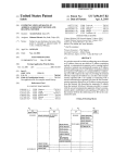
r402
412
43g
/405
I
HEA TOUT
ME77-MNOL FUEL CELL
ME77-MNOL STORAGE
~
"L633"
Pan/E12 007'
MFR/MAL BARRIER
J-
{P \ “432
_L
Oval/T’ ‘r|
l
|
T
434\ 428x
424
IFUEL 0N|
RE-CHAREE
STOkAGE
ELEMENT
To FULL CHARGE A
426
FROM
541%
43,
CONTROLL R
dSLL-‘EP MODE
_ __ DME8_ ._ __
|
{A438
1" '
'
f
UNIT 5
our‘ MIN
l
(POWER
435
[ENABLE
W0
|
,|
R4 TTERY
'\-4zo
. - - -
ENABLE
DE VI5E)
Pl/ CHECK
+
POWER FOR PV
TRANSMIW'ER
ENABLE
- - -
Fl/CHECK
N .9
4
WIREL E55
TRANSMISSION
1
POWER FOR
WIRELESS
TRANSMITTER
_ “ PM? _ _
TR
c410
406
US 8,145,180 B2
Page2
U_S_ PATENT DOCUMENTS
D225,743 S
3,742,450 A
3,808,480 A
l/l973 seltZer ~~~~~~~~~~~~~~~~~~~~~~~ ~~ BIO/102
6/1973 Weller
~ 375/257
4/1974 J9hI1_St9I1_~~
1 317/256
318811962 A
5/ 1975 Rublnsteln
3,885,432
5/1975
A
319241219 A
3,931,532
A
136/209
HerZl
~
73/86112
12/1975 Braun ~~
2/1997
5,606,513 A
5,610,552 A
5,614,123 A
2/1997 Louwagie etal. ..
702/138
3/1997 Schlesingeretal. ........ .. 327/560
3/1997 Kanatzidis et a1. ......... .. 252/582
5,618,471 A
4/1997 Kanatzidisetal. .
5,637,802
6/1997
A
5,644,135
~~ “0/813
5,656,782 A
4,008,619 A
2/1977 Alcalde @1111 ~
73/724
364/571.02
........... ..
310/306
8/1997 Powell, 11 et al.
.... .. 73/756
73/398
5,665,899 A
9/1997 Willcox ,,,,,,,, ..
731/1.63
~429/104
.... .. 29/627
5,682,476 A
5705 978 A
10/1997 Tapperson etal.
M998 Fricket al
395/200.05
3405“
4/1978 HerZ1‘?ta1~ ~
340/87039
9/1978
11/1978
6/ 1979
9/1979
12/1979
Ffedef1°1<_ ~~~~~~~~~~~~~~ ~~
73/861~22
Stachurskl ~~~~~~~~~~~~~~~~~~ 11 136/205
Bell ~~~~~~~ ~~
~ 361/283
Lee ~~~~ ~~
~ 361/283
Bell et al. .
. 361/283
.361/283
416/37
~ 340/595
~ 361/283
Anastasla ~~~~~~~~~~~~~~~~~~ 11 361/283
11/1982 Lee etél ~~~~~~~~~~~~~~~~~~~~ 11 361/283
ll/l982 IWaSakI
73/654
413221775 A
3/1982 Delaton?
4,336,567 A
6/1982
211322133? A
£2; lljrlck
413891895 A
M983 RLYAHJIW
1
Miller
252/582
. . . . ..
8/1977 Jones ~~~~~~~~ ~~
12/1977 Passleretal.
4,287,553 A
9/1981 Braunlich
412971076 A * 10/1981 13011119918131
413221724 A
3/1982 Grudzinski
4,358,814 A
4,361,045 A
A
417/334
......
7/1997
~ ~ ~ 11310/4
A
A
A
A
A
Fricketal,
6/1997 Warrior etal.
~~~~~~~~~~~
410841155 A
McCabe ....... ..
5,642,301 A
1/1977 Nllssf’n 6‘ a1~
4,ll61060
4,125,122
411581217
411681518
4,177,496
Byrd
9/1996 Kunkel ........................... 11 322/3
5,599,172 A 11
410051319 A
4,042,757 A
4,063,349 A
1/1976
338/34
5,554,922 A
1
1
5,722,249 A
3/1998 Miller, 11.,.,,,,,,,,,,,,,,,,,,,,62/2382
5,757,608
5,787,120
5,793,963
5,803,604
5 811201
5/1998
7/1998
8/1998
9/1998
9/1998
A
A
A
A
A *
5’851’083 A
5,870,695 A
5,872,494 A
Bernot et a1.
Louagie et a1. .
Tapperson etal.
Pompei
Skowronski
. 361/283.4
375/257
395/200.31
374/181
429/17
Palm
'
Brownét'alw
Palan etal.
5,899,962 A
M1998
2/1999
2/1999
5/1999
Louwagie etal.
"403/337
702/138
"I 333/252
702/138
5,911,162 A
6/1999
Denner ,,,,,,,,, H
,, 73/718
5929372 A
5954526 A
7/1999 Oudoire etal. .
9/1999 srriith ,,,,,,,, ,.
136/208
439/136
5,957,727 A
9/1999 Page, Jr
.. 439/60758
W724
5,978,658 A
11/1999 Shoji ................... .. 455/66
5,992,240 A
11/1999
4,390,321 A
4,422,125 A
6/1983 Langlols etal.
12/1983 Antonazzietal. .
417/15
. 361/283
6013 204 A
6’038’927 A
V2000
W000
4,422,335 A
4,434,451 A
12/1983 Ohnesorge etal.
73/724
2/1984 Delatorre .................... .. 361/283
6’079’276 A
6’104’759 A
60000
8/2000
" 73%
"'3'75/295
4,455,874 A
4,458,537 A
6/1984 Paros ............................ 11 73/704
7/1984 Bell et al. .
73/718
6’109’979 A
6’126’327 A
872000
10/2000
439/709
" 709/221
10/2000 Appa
290/55
11/2000
,,,,,,,,,,,,,,,,,,,,,,,,,,,, “323/273
30001
1310/46
4,475,047 A
4,476,853 A
: ~~~~~ '1
Tsuruokaetal.
.. 73/718
- -
252584
W706
307/66
1 126/578
4,485,670 A
10/1984 Ebe1t,Jr. ..
10/1984 Arbogast
12/1984 carnarda etal.
73/179
6’l27’739 A
6,150,793 A
15439177 S
4,490,773 A
12/1984
. 361/283
D439’l78 S
30001
307/66
D439’179 S
30001
' 1310/46
. 361/283
73/718
D439’l80 S
D439,181 S
30001
3/2001
' DID/85
, D10/46
Moffatt ..... ..
4,510,400 A
4/1985 Kiteley
4,542,436 A
4,562,742 A
9/1985 Carusillo .
1/1986 Bell ~~~~~~~ 11
4,570,217 A
2/1986 Allen etal.
4,590,466 A
5/1986 Wik1und etal.
A *
1
gilglsngbjfk
A
1
5/2001 Tapperson et a1. .......... .. 340/825
7/2001
E63 ~~~~~~~~~~~~~~~~~~~~~~~~~~~~~~
6,282,247 B1
8/2001 Shen .......... ..
Tjamér'gt'gl"
6,295,875 B1
6/1988 SZabO 611111
151533
Metal ~
1
~
11340/87031
Avg/17(1)?‘
Fricketal ~ ~ ~ ~ ~ ~
6,312,617 B1
11/2001
Kanatzidisetal.
6,326,764 131*
12/2001 Virtudes ,,,,,,,,,,,,,, ..
320/101
6,338,283 B1
1/2002 Blazquez Navarro .
73/8658
3/2002
5/2002 Fellows
324/60
6,405,139 B1
6/2002 Kicinskié1,,,, .
5/1990 Possum etal- ~~~~~~~~~~~~~~~~~~~~ ~~ 73/4
8/1990 Granthametal. .... ..
361/283.1
6,429,786 B1
6,441,747 B1
51/2002
@2002
12/1990 Nlshlhara
A
l/l991
Gross
~~~~~~~
510091311 A
4/1991
Schenk ~~~~~ ~~
73/724
252/623
Ruckleyetal.
709/250
60/517
Bansemiretal.
Khairetal,
....,, 702/33
.. 340/870.27
n 340/87016
10/2002 Behm etal, ................... .. 73/753
B1
11/2002
Lovoi ......................... ..
455/41.2
~ 206/332
6,484,107 B1
11/2002
Roper et al.
.. 702/50
12/2002 Behm et al
5/1991 Kelleheretal.
363/26
6 487912 B1
6/1991
361/56
6’504’489 B1
V2003
.
73/753
' '''''
' "'3'40/8703
320/32
6’508’131 B2
M2003
'
5,060,295 A
10/1991
. 455/186
6’510’740 B1
V2003
"" " 73/708
5,094,109 A
D331,370 s
5,168,419 A
3/1992 Dean et a1. 11111111111111111111 11 73/718
12/1992 Williams ..................... .. D10/46
12/1992 Delatorre
. 361/283
6,511,337 B1
5471’829 S
239/320
D10/g5
D472’831 S
1/2003
3/2003
40003
5,170,671 A
5,194,819 A
12/1992 Miau etal.
3/1993 Briefer
73/861.22
73/718
6 546’805 B2
6’553’076 B1
400%
400%
. 310/339
73/733
6’568’279 B2
6’57l’132 B1
500%
500%
6,574,515 B1
6/2003 Kirkpatrick et a1. .......... .. 700/19
5,223,763 A
5,230,250 A
6/1991 Ishiietal.
.
6,457,367 B1
377/6
5,023,746 A
5,025,202 A
~ ~ ~ ~ ~~ 73/718
6,430,699
~ ~ ~ ~~
5,014,176 A
Epstein ..... ..
375/285
10/2001
6,360,277 B1
10/1989 Schulte ‘ital
4,977,480 A
.. 429/30
6385 972 B1
418781012 A
~
George et a1.
. 73/151
10/1989 Delatorre
4,982,412
‘gm/825 07
~
4,875,369 A
4,926,674 A
4,951,174 A
' DIG/52
‘257/419
6,255,010 B1
~
£231??? A
50001
5/2001
6,236,334 B1
1
4,749,993 A
1
“A987
D44l’672 S
62363096 B1
1 ~~~~~~~~~~~~~ "
1
417041607 A
700/19
340/870.28
' 1310/46
Borrasetal.
6/1993 Chang .... ..
7/1993 Delatorre ..... ..
A
73/75'6
'
Davisetal
"
700/2
53293818 A
M994 Prick et a1‘ "
73/708
6,593,857 B1
7/2003
Roper et al. ...... ..
. 340/870.3
5,412,535 A
5,1995
Chao et a1‘ "
' 361/700
6,609,427 B1
8/2003
West?eldetal.
.... .. 73/753
5,492,016
5,495,769 A
2/1996
3/1996 Pinto
Broden
etal.
etal...
73/724
73/18
616“01308
616611220 B1
10/2003
12/2003 Keyghobadeta1~
5,506,757 A
4/1996 Brorby ............. ..
. 361/796
616621662 B1
12/2003
5,531,936 A
7/1996 Kanatzidisetal.
. 252/587
66671594 B2
12/2003
5,542,300 A
5,554,809 A
8/1996 Lee .............. ..
73/724
9/1996 Tobita etal. .................. .. 73/700
6,680,690 B1
6,711,446 B2
1/2004
3/2004
US 8,145,180 B2
Page 3
6,744,814 B1
6,747,573 B1
6/2004
6/2004
6,765,968 B1
7/2004 Nelson et al.
6,774,814 B2
6,778,100 B2
6,792,259 B1
8/2004
8/2004
9/2004
6,794,067 B1*
6,823,072 B1
6,838,859 B2
Blanksby et al. ........... .. 375/232
Gerlach et al. .
340/87021
...... .. 375/257
Hilleary ................. .. 340/870.07
Schempf ................ .. 340/870.07
Parise .... ..
. 455/343.1
10/2004
10/2004
2004/0218326 A1
11/2004 Duren et al.
2004/0242169 A1
2004/0249483 A1*
2004/0259533 A1
12/2004
12/2004
12/2004
6,839,546 B2
6,839,790 B2
. 429/408
381/7
322/38
1/2005 Hedtke .................... .. 455/67.11
1/2005 Barros De Almeida
2005/0011278
2005/0017602
2005/0023858
2005/0029236
2005/0040570
6,843,110
6,891,477
6,891,838
6,898,980
6,901,523
et al. ........................... ., 710/305
1/2005 Deane et al.
. 73/114.35
5/2005 Aronstam
340/606
5/2005 Petite et a1. .
. 370/401
5/2005 Behm et al. .
73/756
5/2005 Verdun ....................... .. 713/320
B2
B2
B1
B2
B2*
9/2004 Acker et al.
11/2004 Hoover
1/2005 Shah
2004/0211456 A1
2004/0214543 A1
A1
A1
A1
A1
A1
Brown et al.
Arms et al. ..
Bingle et al.
Gambino et al.
Asselborn
2005/0044241 A1*
2005/0046595 A1
2/2005
3/2005
Dunstan
709/228
Blyth .......................... .. 340/908
2005/0056106 A1
2005/0072239 A1
3/2005 Nelson et al. .............. .. 73/866.3
4/2005 Longsdorfet al.
.. 73/649
4/2005 Yoo ................... ..
415/4.3
4/2005 Kanatzidis et al
136/239
2005/0074324 A1*
6,904,295 B2
6,907,383 B2
6/2005 Yang ........................... .. 455/522
6/2005 Eryurek et al
. 702/183
6,910,332 B2
6/2005
60/520
6,942,728 B2
9/2005 Caillat et al.
117/3
700/19
6,961,624 B2* 11/2005 Kirkpatrick et al.
6,984,899 B1*
6,995,677 B2
1/2006 Rice ................. ..
2/2006 Amnstam et a1, ,
6,995,685 B2
2/2006
7,010,294 B1
3/2006 Pyotsia et a1.
7,036,983 B2
5/2006 Green et al.
7,058,542 B2
6/2006 Hauhia et al.
7,073,394 B2
7/2006
7,088,285 B2
7,109,883 B2
7,116,036 B2
. 73/861.18
310/339
.... .. 296/76
219/121.69
.... .. 266/99
4/2005 Tsujiura
5/2005 Hirsch ..
310/339
290/42
2005/0109395 A1
5/2005
.. 137/8
2005/0115601 A1
6/2005 Olsen et al. ..
2005/0118468 A1
6/2005 Adams et al.
2005/0122653 A1*
2005/0130605 A1
6/2005
6/2005
McCluskey eta.
Karschnia et al. ..
Seberger ..
136/212
429/22
. 361/92
455/90.3
340/870.39
2005/0132808 A1
6/2005
Brown et al.
.... .. 73/592
455/420
2005/0134148 A1
6/2005 Buhler et al.
310/339
. 374/179
2005/0139250 A1
6/2005 DeSteese et al.
702/183
2005/0164684 A1
7/2005
Chen et al. .... ..
. 455/141.1
. 73/861.22
2005/0182501 A1
8/2005
Franchuk et al.
.... .. 700/81
8/2006 Smith ......................... .. 342/124
2005/0201349 A1
9/2005 Budampati
9/2006
10/2006
Randall ........ ..
290/44
340/606
361/93.1
Albsmeier et al. ............ .. 455/91
WojsZnis et al. .............. .. 700/52
Nixon et al.
. 455/414.1
1/2005
1/2005
2/2005
2/2005
2/2005
2005/0076944 A1
2005/0082949 A1*
2005/0099010 A1
Fellows .... ..
Brown et al. ............... .. 136/243
Osone et al. .
. 455/197.2
Foster .... ..
Trimble et al. ........ .. 340/870.16
Balasubramaniam
et a1,
2005/0208908 A1
2005/0222698 A1
136/212
370/342
9/2005
10/2005
Karschnia et al. .
Eryurek et al. .
James
. 455/127.1
.... .. 700/90
,,,,,,,,,,,,,,,,,,,,,,,,,,, ,, 310/322
2005/0228509 A1
10/2005
7,173,343 132*
2/2007 Kugel ,,,,,,,,,,,,,,,,,,,,,,,,, ,, 290/1R
2005/0245291 A1
11/2005 BroWn etal.
7,197,953 B2
4/2007
2005/0273205 A1*
12/2005
Nickerson etal. .......... .. 700/284
Shepard etal. ............. .. 370/254
01in ,,,,,,,,,,,,,,,,,,,,,,,,,,, ,, 73/g665
........ ..
.. 700/19
455/572
7,233,745 B2
6/2007 Loechner
, 398/128
2005/0276233 A1
12/2005
7,262,693 B2
55/2007 Karschnia et a1, ,
, 340503
2005/0281215 A1
12/2005 Budampatiet a1. .
370/328
7,271,679 B2
9/2007
,,,, H 333/24
2005/0289276 A1
12/2005
Karschnia et al. ..
710/305
7,301,454 B2
Lundberg @131, H
11/2007 Seyfang et a1, ,
H 340/53926
2006/0002368 A1
1/2006 Budampatiet al. .
370/351
. 174/5062
2006/0028327 A1
2/2006
Amis ......... ..
340/431
290/2
2006/0036404 A1
2/2006 Wiklund et al.
702/183
, 439/573
2006/0060236 A1
3/2006 Kim et al.
136/203
Nelson ,,,,,,,,,,,,,,,,,,,,,,,,,, ,, 322/37
2006/0063522 A1
3/2006
455/423
7,319,191 B2
1/2008
7,329,959 B2
Z/goog Kim et a1,
7,351,098 B2
4/2008 Gladd et a1,
7,560,907 B2
7/2009
7,626,141 B2
P0011 etal. ..
12/2009 R0dIigueZ_Medina
et a1‘ “““““““““““““““““ “ 219/260
7,726,017 B2
7,983,049 B2
2001/0025349 A1
6/2010
Evans et a1‘ ‘
29/854
7/2011 Leifer et a1‘
9/2001 Sharood etal
‘ 36l/728
. 713/340
4/2006 Brahmajosyula et al.
4/2006
Stefener et al. ............... .. 429/34
2006/0092039 A1
5/2006
Saito et al. .... ..
.. 340/82537
2006/0128689 Al*
2006/0131428 A1
6/2006 Gomtsyan et al.
6/2006 Wang eta1~
.. 5l4/2l7.0l
235/492
1/2002
2006/0134470 A1*
6/2006
3/2002 Eryurek at a]
5/2002 Loechner
_ 702/183
' 702/188
2006/0148410 A1
2006/0181406 A1
7/2006 Nelson et al.
8/2006 Petite et al
2002/00g2799 A1
2002/0095520 A1
6/2002 Pramanik
7/2002 Wettstein etal.
' 702/130
. 709/253
2006/0227729 A1
2006/0266404 A1
10/2006 Budampatietal
11/2006 Hiller eta1~
370/278
136/205
2002/0097031 A1
2002/010596g A1
7/2002 Cook et a1‘
g/ZOOZ Pruzan et a1‘
‘ 323/273
' 370/465
2006/0274644 A1
2006/0274671 A1
12/2006 Budampati et al. .
12/2006 Budampatiet a1. .
370/216
370/254
2006/0287001
2006/0290328
2007/0006528
2007/0030816
2007/0030832
12/2006
12/2006
2003/0043052 A1
2003/0079553 A1
mun/0083038 A1
10/2002
11/2002
Bell ,,,,,,, n
Kasai et al. .
62/33
. 323/284
2/2003
Kogure ,,,,, n
n 340/35
2/2003
3/2003
3/2003
5/2003
5/2003
Mickle etal.
. 600/509
Holder et a1, ,,,,,,,,,,,,,,, n 290/1A
Tapperson etal. ..... .. 340/82537
Cain et a1‘ ““ “
' 73/861‘27
POOH et a1‘ “
455/344
2003/0097521 A1
5/2003 pfandler et a1‘
2003/0l34161 A1>I<
2003/0143958 A1
2003/0167631 A1
7/2003
7/2003
9/2003
Gore et a1‘ “
Elias et al. ..
Hallenbeck ,
‘ 711/103
A1
A1
A1
A1
A1
2007/0039371 A1
2007/0054630 A1
2007/0055463 A1*
2007/0135867 A1*
Kaye et al.
370/310
2002/0029130 A1
2002/0065631 A1
A1
A1
A1
A1
A1*
73/71g
2006/0077917 A1
2006/0088751 A1*
2002/0011115 A1
2002/014g236
2002/0163323
2003/0030537
2003/0032993
2003/0042740
prick ,,,,,,,,,,,, n
McFarland ........... ..
Budampatiet a1. .
. 455/552.1
Qrth ~~~~~~~~~~~~~~~~~~~~~~~~~~~~ ~- 323/218
1/2007
Dlebold et al.
2/2007
2/2007
2/2007
3/2007
3/2007
Kolavennu ~~~~ ~
Gonla et al. .
Omat? eta1~
Schelble et al.
FlorenZ et al. .... ..
........... .. 48/197R
6/2007 Klosterman et al.
429/12
455/73
29/g35
2007/0229255 A1
2007/0233283 A1
2007/0237137 A1
10/2007
10/2007
10/2007
2003/0171g27 A1*
2003/0199778 A1
9/2003 Keyes et a1,
700/19
10/2003 Mickle etal. ............... .. 600/509
2007/0273496 A1
2007/0275755 A1
11/2007 Hedtke ...... ..
11/2007 Chae eta1~
2003/0204371 A1
10/2003
Sciamanna ,,,,,,,,,,,,,,,,, u 702/1g3
.... .. 429/12
. 455/67.ll
340/521
~ 370/252
370/338
~~~~ ~- 73/9
.. 455/90.3
.. 702/50
.. 607/60
Loechner ...... ..
340/540
Chen ~~~~~ ~~_~ ~~~~~~~~~~~~~~~~~~~~~ ~~ 700/17
McLaughlin ............... .. 370/389
340/506
455/557
2007/0279009 A1
12/2007
429/26
2007/0280144 A1
12/2007 Hodson et al. .............. .. 370/312
Faust ..... ..
. 342/124
LitWin ........................ .. 374/120
2007/0280178 A1
2007/0280286 A1
12/2007
12/2007
Hodson et al. ..
Hodson et al. .... ..
Parise ......................... .. 455/572
Marganski et al.
95/116
9/2004 West?eld et al. ..
. 375/219
10/2004 Hedtke ..... ..
710/37
2007/0280287
2007/0282463
2007/0285224
2007/0288204
12/2007
12/2007
12/2007
12/2007
Samundrala et al. ..
Hodson et al. .... ..
Karschnia et al.
Gienke et al.
2004/0200519 A1
10/2004
. 136/238
2008/0010600 A1
1/2008
2004/0203434 A1
10/2004 Karschnia et al. ....... .. 455/67.11
2008/0054645 A1
3/2008 Kulkarniet al.
2004/0081872 A1*
4/2004 Herman et a1
2004/0085240 A1
2004/0086021 A1
5/2004
5/2004
2004/0142733
2004/0159235
2004/0184517
2004/0199681
7/2004
8/2004
A1
A1
A1
A1
SterZelet al. ..
A1
A1
A1
A1
Kobayashi .................. .. 320/166
370/338
.. 370/466
370/466
.. 700/20
340/538
702/188
Katano ....................... .. 715/748
US 8,145,180 B2
Page 4
2008/0083446 A1
2008/0088464 A1
2008/0123581 A1
4/2008 Chakraborty et al. ...... .. 136/205
4/2008 Gutierrez .................... .. 340/606
5/2008 Wells et a1.
W0
W0
WO 2004/059139
WO 2004/082051
7/2004
9/2004
W0
WO 2004/094892
11/2004
2008/0141769 A1
2008/0280568 A1
6/2008 Schmidt et a1. .......... .. 73/20419
11/2008 Kielb et a1. ................ .. 455/741
W0
W0
WO 2005/086331
WO 2006/109362
9/2005
10/2006
2008/0310195 A1
12/2008 Seberger et al.
363/26
W0
WO 2007/002769
1/2007
2009/0015216 A1
2009/0066587 A1
1/2009 Seberger et al.
3/2009 Hayes et al.
. 323/234
. 343/702
W0
W0
WO 2005/060482
WO 2009/003146
7/2007
12/2008
2009/0081957 A1
3/2009
Sinreich .... ..
455/68
W0
WO 2009/003148
12/2008
2009/0167613 A1
7/2009 Hershey et al
. 343/702
W0
WO 2009/063056
5/2009
2009/0195222
8/2009
. . . ..
A1
2009/0200489 A1
Lu et a1.
......
8/2009 Tappel et al. ............ .. 250/4923
10/2009 Hedtke ,,,,,,,,,,,,,,,,,,,,,,,,, H 73/579
12/2009 Vanderaa e131, ,,,,,,,,,, H 455/903
2009/026043g A1
2009/0311975 A1
FOREIGN PATENT DOCUMENTS
CN
CN
CN
CN
DE
DE
DE
1251953
14293 54
1442822
100386602 C
2710211
3340834 A1
3842379
5/2000
7/2003
9/2003
4/2005
9/1978
5/1985
6/1990
5/1996
DE
DE
DE
DE
196 22
201 07
10104
100 41
295
112 U1
582 A1
160
7/2001
10/2001
3/2002
DE
102 21 931 A1
5/2002
DE
EP
EP
10 2004 020 393
0 518 916 B1
0 524 550 A1
11/2005
2/l99l
1/1993
EP
EP
0 895 209 Al
0 945 714
2 / 1999
9/l999
EP
EP
1 202 145
1 202 145 A1
50002
5/2002
EP
EP
Ep
Ep
1 192 614
1 293 853
1 482 568 A2
1879294
100%
3/2003
12/2004
1/2008
F1
322/3
118699 B
A
A
A
A
OTHER PUBLICATIONS
Larwood et al., Controlled Velocity Testing of an 8-kW Wind Tur
bine, American Wind Energy Association’s WindPower 2001 Con
ference, Jul. 2001.*
Schmidt, Piezoelectric Energy Conversion in Windmills, IEEE,
1992*
Schmidt, Theoretical Electric Power Output Per Unit Volume of PVf
and Mechanical to Electrical Conversion Ef?ciency as Functions of
Frequency, IEEE 1986*
The International Search Report and Written Opinion in Appln. No.
PCT?JS2006/035728, ?led Sep. 13,2006.
USA & Metric Thread Standards http://www.carrlane.com/Catalog/
index.cfm/29425071FOB221118070C1C513906103E05543BOB
05543BOB012009083C3B285357474A2D020609090C0015312A
365l5F5-54A5B'
Noti?cation of Transmittal of the International Search Report or the
Declarat1oniPCT/US03/
10403.
..
>9
W1reless R&D A1ms to Boost Traf?c , by M. Moore, InTech with
Industrial
Computing, Feb. 2002, 3. pgs.
‘1
,
,,
System Checks Faraway Mach1nes Health , by J. Strothman,
InTech with Industrial Computing, Feb. 2002, 1 pg.
“Wireless Management Toolkit XYR 5000”, by Honeywell Interna
tional Inc., Phoenix, Arizona, 3 pgs., Oct. 2003.
“Wireless Analog Input Transmitters XYR 5000”, by Honeywell
International Inc., Phoenix, Arizona, 4 pgs., Oct. 2003.
“Quad Analog Output Module Installation and User’s Manual”, by
Honeywell International Inc., Phoenix, Arizona, pp. Ii, iii, iv and
2/2008
1'12, D90 2003
6/ 1975
4/19g5
3/ 1996
7/ 1998
6/2004
4/ 1984
Internat1onal Search Report and Wr1tten Op1n1on of Appl1cat1on No.
PCT/US2005/015848, ?le May 5, 2005.
“Wireless Dual Analog Input Interface Transmitter Installation and
User’s Manual”, by Honeywell International Inc., Phoenix, Arizona,
pp. Ii-vi and 7-43, Dec. 2003.
“XYR 5000 Wireless Dual Analog Input Interface, Model Selection
_
_
_
_
_
GB
GB
GB
GB
GB
JP
1 397 435
2 145 876
2293446
2 320 733
2 403 043
59-075684
JP
60-125181
7/ 1985
Guide”, by Honeywell International Inc., Phoenix, Arizona, Dec.
JP
02 067794
3/1990
2003.
JP
06 199284 A
7/ 1994
“Wireless Measure, Monitor & Control”, by Accutech, 4 pgs. May
JP
09-182308
7/1997
2003.
JP
ll-03698l
2/1999
“Wireless Instrumentation, Multi-Input Field Unit”, by Accutech, 2
JP
11-215867
8/1999
pgsq Dec, 2003,
JP
JP
JP
11/1999
11/2001
12/2002
“Quad Analog Output Module”, by Accutech, 1 pg. Dec. 2003.
3 Pages from Website www.chemicalprocessing.com, Apr. 2004.
4 Pages from Website http://content.honeywell.com/imc/eznews/
JP
JP
JP
JP
JP
JP
11303726
2001524226
2002369554
2003/042881
2003051894
2003134261
2003495903
2004021877
2004 069197
2/2003
2/2003
5/2003
7/2003
1/2004
3/2004
JP
'
2004 146254
5/2004
JP
2004208476
7/2004
JP
2005_72080
3/2005
eznews0403/news.htm, 2004.
The International Search Report and Written Opinion in Appln. No.
PCT?JS2005/021757, ?led Jun. 21, 2005.
The First Communication of European Patent Application 06 80
3540'1’ ?led Sep' 13’ 2006'
First Of?ce Action of Chinese patent application 200580006438.X,
?led Mar. 2, 2005.
.
,
1
.
f
1.
.
Examlriliciri consu tat1on or European patent app 1cat1on 05 724
RU
RU
2 131934 (:1
2168062 CI
6/1999
50001
115903’.
5. Ma“ 2’ 2005'
.
.
.
xam1nat1on Report of the European Patent Of?ce 1n Appl1cat1on No.
057241903, ?led Mar. 2, 2005.
RU
2003128989
1/2007
SU
1746056
7/1992
The Of?c1al Commun1cat1on 1n Appl1cat1on No. 057462418, ?led
1813916 A1
5/1993
May 5’ 2005'
SU
W0
W0
W0
W0
W0
W0
W0
W0
.
.
.
.
.
.
.
.
.
.
WO 88/05964
WO 91/11029
WO 91/13417
WO 95/07522
W0 99/53 286
W0 01/218723
WO 02/05241
W0 03/023536
8/1988
7/1991
9/1991
3/1995
10/ 1999
7/2001
1/2002
3/2003
Second Of?ce Act1on from Ch1nese Patent Appl1cat1on No.
20058001425124 ?led May 5, 2005.
Second Of?ce Action from Chinese patent application No.
2005800142124 ?led May 2005.
Noti?cation of Transmittal of the International Search Report and the
Written Opinion, PCT/US2007/019636, dated Oct. 1, 2008.
Invitation to Pay Additional Fees and Partial Search Report, PCT/
US2007/019396, dated Oct. 7, 2008.
W0
W0 03/089881
10/2003
The Of?cial Action in Application No. 2006145434/09, ?led May 5,
W0
WO 2004/038998
5/2004
2005.
US 8,145,180 B2
Page 5
First examination report for Indian application No. 3589/CHENP/
2006, dated Apr. 17, 2009.
Second Of?ce Action from Chinese patent application No.
200580006438.X, dated Apr. 10, 2009.
Third Of?ce Action from Chinese patent application No.
2005800142124, dated Dec. 19,2008.
Of?cial Action from Russian patent application 2008116682, dated
Jan. 16, 2009.
Second Of?cial Action from Russian patent application No.
2008116682, ?led. Sep. 13,2006.
Decision on refusal to grant a patent for invention for Russian patent
application No. 2006145434, ?led May 5, 2005.
Fourth Of?ce Action for Chinese patent application No.
2005800142124, dated Jul. 24, 2009.
Of?cial Letter for Mexican patent application No. PNN2006/
013488, dated Jun. 25, 2009.
Fourth Of?cial Action issued for Russian patent application No.
2008116682, dated Dec. 18,2009.
English machine translation of JP2004208476 A.
“Every Little Helps,” Economist, vol. 278, No. 8469, p. 78, Mar. 18,
2006.
“Thermal Design and Heat Sink Manufacturing & TestingiTotal
Thermal and Heat Sink . . . ,” http://www.enertron-inc.com/enertron
products/integrated-heat-sink.php, Mar. 31, 2006.
Of?ce Action from US. Appl. No. 11/028,486, dated May 9, 2008.
“Heat PipeiWikipedia, the free encyclopedia,” http://en.wikipedia.
org/wiki/Heatipipe, Mar. 31, 2006.
“High Power Single PSE Controller With Internal Switch,” Linear
Technology LTC4263-1, p. 1-20.
Of?ce Action from European patent application No. 078377694,
dated Jul. 14, 2009.
First Of?ce Action from Australian patent application No.
2005248759, dated Apr. 30, 2009.
Second Of?ce Action from Australian patent application No.
2005248759, dated Aug. 28, 2009.
Search Report and Written Opinion for international patent applica
tion No. PCT/US2009/002476, dated Apr. 21, 2009.
Third Of?ce Action from Chinese patent application No.
200580006438.X, dated Sep. 28, 2009.
First Of?ce Action from Chinese
2005800142124, dated Mar. 14, 2008.
First Of?cial Action from Russian
2006134646, dated Mar. 12, 2008.
First Of?cial Action from Russian
2008103014, dated Jun. 9, 2009.
First Of?ce Action for Chinese
200680015575.4, dated Oct. 31, 2008.
Fifth Of?ce Action from Chinese
2005800142124, dated Nov. 13, 2009.
Second Of?ce Action for Chinese
2002 Microchip Technology Inc., “Stand-Alone CAN Controller
with SPITM Interface,” pp. 1-75, Mar. 1, 2002.
Rosemount Reference Manual 00809-0 100-4022,Rev AA, Jul. 2002,
“Model 4600 Oil & Gas Panel Transmitter,” 65 pages.
Transmitter Schematic, Sold Jul. 2002, 5 pages.
Noti?cation of Transmittal of the International Search Report and the
Written Opinion for the international patent application No. PCT/
US2010/047463 dated Dec. 1, 2010.
Noti?cation of Transmittal of the International Search Report and the
Written Opinion of the International Searching Authority for Inter
national Application No. PCT/US2006/025206 dated Nov. 10, 2006.
“Mechatronic Drives in Mobile Hydraulics,” Internet Article,
Soncebox News. No. 4, Oct. 2004.
Of?ce Action from European Application No. 058538083, dated
Nov. 6, 2007.
The International Search Report and Written Opinion in Application
No. PCT/US2009/003619, dated Sep. 30, 2009.
The International Search Report and Written Opinion in Application
No. PCT/US2006/035728, dated Jan. 12,2007.
“Noti?cation of Transmittal of the International Search Report and
The Written Opinion of the International Searching Authority” for
PCT/US2008/011451 dated Mar. 30, 2009.
The International Search Report and Written Opinion in Application
No. PCT/US2009/003616, dated Jan. 13,2010.
First Examination Report for Indian patent application No. 4676/
CHENP/2006 dated Apr. 17, 2009.
The International Search Report and Written Opinion in Application
No. PCT/US2009/003611, dated Nov. 4, 2009.
The International Search Report and Written Opinion in Application
No. PCT/US2009/003621, dated Sep. 30, 2009.
Rejection Notice for Japanese patent application No. 2007527282
dated Jul. 22, 2010.
Summons to attend oral proceedings for the European application
No. 057462418 dated May 26, 2010.
The sixth Of?ce Action from Chinese application No.
20058000142124, dated Aug. 17,2010.
The seventh Of?ce Action from Chinese patent application No.
2005800142124 issued on Jan. 31, 2011.
Noti?cation of Transmittal of the International Search Report and the
Written Opinion for International application No. PCT/US2009/
patent application No.
062152 dated Jun. 2, 2010.
First Of?ce Action for Chinese application No. 200780018710.5
patent application No.
Noti?cation on Results of Examining the Invention for Patentability
patent application No.
from Russian patent application No. 2006145434 dated Aug. 1,2008.
First Rejection Notice issued for Japanese patent application No.
patent
application
No.
patent application No.
patent application No.
200680015575.4, dated Sep. 25, 2009.
Second Of?cial Action for Russian patent application No.
2006145434, dated Apr. 2, 2008.
First Of?ce Action for Chinese patent application No.
2006800352485, dated Nov. 6, 2009.
Third Of?cial Action for Russian patent application No.
2008116682, dated Sep. 11, 2009.
Communication from European Patent Of?ce dated Mar. 2, 2010 for
European application No. 06 803 540.1.
Foundation Fieldbus Power Supply, A Look at Powering Fieldbus,
www.analogservices.com/fbsupp2.pdf, Oct. 22, 2000.
Fourth Of?ceAction from Chinese application No. 2005/80006438.x
dated May 17, 2010.
First Of?ce Action from Japanese patent application No. 2008
532280 dated Mar. 1, 2011.
US. Appl. No. 12/855,128, ?led Aug. 12,2010.
Of?ce Action from European Application No. 057462418, dated
Aug. 29, 2007.
International Search Report for International Application No. PCT/
US 03/27561, ?led Mar. 9, 2003, dated Jun. 15, 2004.
dated May 12,2010.
2007-527282 dated Dec. 14, 2009.
The Of?cial Communication from European patent application No.
057462418 dated Nov. 12, 2010.
The Minutes in accordance with Rule 124(4) EPC for European
application No. 057462418 dated Nov. 4, 2010.
Communication pursuant to Rules 161 and 162 EPC from European
patent application No. 09767057.4 dated Jan. 26, 2011.
Communication pursuant to Rules 161 and 162 EPC from European
patent application No. 097670632 dated Jan. 28, 2011.
Communication from corresponding EP application No. 088372362
dated Nov. 3, 2010.
Noti?cation of Transmittal of the International Search Report and the
Written Opinion for the international patent application No. PCT/
US2010/047444 dated Dec. 10, 2010.
Third Of?ce Action for Chinese patent application No.
200680015575 .4, dated Jun. 2010.
Decision on Refusal to Grant from Russian patent application No.
2006145434 dated Feb. 18, 2011.
Second Examination Report for Indian patent application No. 4676/
Chenp/2006 dated Apr. 8, 2010.
The International Search Report and Written Opinion in Application
No. PCT/US2009/003636, dated Oct. 6, 2009.
Second Of?ce Action for the corresponding Chinese patent applica
tion No. 200680035248.5 dated Oct. 19, 2011.
* cited by examiner
US. Patent
Mar. 27, 2012
Sheet 1 0111
US 8,145,180 B2
12
10
CON TROL
5Y5 TEM
M
|__..|____
ICIRC'UITRV
l
(PRIOR ART)
US. Patent
Mar. 27, 2012
Sheet 2 0111
12’\
CONTROL
5Y5 TEM
16
r 14
FIELD
DEVICE
F18
[/0
P0 WER
L__+ (20
ACTUA TOR /
TRANSDUCER
Fig. 2
(PRIOR AR 7-)
US 8,145,180 B2
US. Patent
10
2‘
Mar. 27, 2012
Sheet 3 or 11
US 8,145,180 B2
ML CONTROL
SYS TEM
24
A
(34
C?
FIELD DEVICE
—>
~26
WIRELESS
COMM UNICA 7TONS
32
PO WER
—->
CON TROLL ER
{'20
35)
ACTUA TION
TRANSDUCER "——
Fig. 3
US. Patent
Mar. 27, 2012
1'94
Sheet 4 0111
US 8,145,180 B2
US. Patent
Mar. 27, 2012
Sheet 5 or 11
US 8,145,180 B2
A
A
T_/_]Z0
ENE/26y
ANTENNA
CONVERTER
CONTROLLER <
365
—
\
[0?5725'507
>
366
3L2
I
Lil/F2’!
K374
F370
IF - - - - - -|
BA TTb-py 4
> MEMORY
I LCD DISPLAY I
M
— — —
— — —
376
‘
CLOCK
~P114
L372
4/360
LOOP
#368
comm UNICA Top
I
I
112
Fig. 5 A
US. Patent
Mar. 27, 2012
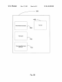
' Wind-Powered Generator
Sheet 6 0f 11
/\
602
Thermopile
700
Compressed-Gas based
/\
generator
702
_________________________________ __
Fig. 5B
US 8,145,180 B2
Fuel Cell
US. Patent
Mar. 27, 2012
Sheet 7 0f 11
416
US. Patent
Mar. 27, 2012
Sheet 8 or 11
US 8,145,180 B2
US. Patent
Mar. 27, 2012
Sheet 9 or 11
US 8,145,180 B2
WIRELESS
COMM UNICA U'ONS
MODULE
O
HYDROCARBON-BASED
PROCESS FLUID
if
Fly. 8
US. Patent
Mar. 27, 2012
Sheet 10 0f 11
US 8,145,180 B2
SUPPOR T
Fig. 9A
608
614 602
615
604
610
600
Fig. 9B
US. Patent
Mar. 27, 2012
Sheet 11 0f 11
US 8,145,180 B2
624
624
626
632
f // 625
/ 623
634
628
630
/610
622
620
604
600
Fig. 108
US 8,145,180 B2
1
2
POWER GENERATION FOR PROCESS
DEVICES
alternative, the process control loop can carry digital signals
used for communication With ?eld devices. Digital commu
nication alloWs a much larger degree of communication than
analog communication. Field devices that communicate digi
tally can respond to and communicate selectively With the
CROSS-REFERENCE TO RELATED
APPLICATIONS
control room and/or other ?eld devices. Further, such devices
can provide additional signaling such as diagnostics and/or
alarms.
In some installations, Wireless technologies have begun to
be used to communicate With ?eld devices. Wireless opera
This application is a continuation-in-part application of
US. patent application Ser. No. 10/850,828, ?led May 21,
2004, entitled WIRELESS POWER AND COMMUNICA
TION UNIT FOR PROCESS FIELD DEVICES.
tion simpli?es ?eld device Wiring and setup. Wireless instal
BACKGROUND OF THE INVENTION
lations are currently used in Which the ?eld device is manu
factured to include an internal battery, potentially charged by
The present invention relates to industrial process control
a solar cell Without any sort of Wired connection. Problems
exist in using an internal battery as the energy demands of
Wireless devices may vary greatly depending on numerous
and monitoring systems. More speci?cally, the present inven
tion relates to the generation of electrical poWer for such ?eld
devices.
In industrial settings, control systems are used to monitor
and control inventories of industrial and chemical processes,
and the like. Typically, the control system performs these
functions using ?eld devices distributed at key locations in the
industrial process and coupled to the control circuitry in the
factors such as the device reporting rate, device elements, et
cetera.
20
control room by a process control loop. The term “?eld
device” refers to any device that performs a function in a
distributed control or process monitoring system, including
all devices used in the measurement, control and monitoring
of industrial processes.
Field devices, also referred to herein as process devices, are
used by the process control and measurement industry for a
variety of purposes. Usually such devices have a ?eld-hard
ened enclosure so that they can be installed outdoors in rela
25
Di?iculties also arise in installations Where solar poWer is
not reliable. For example, it becomes problematic to use solar
poWer in areas that experience full shade tWenty-four hours a
day, seven days a Week, or in parts of the World Where solar
isolation numbers are very small, such as in the Arctic circle.
Accordingly, in these installations, poWering a Wireless pro
cess device using solar poWer is not reliable. Accordingly,
there is an ongoing signi?cant need for Wireless process
devices that can operate using an abundant reneWable source
of poWer that is not dependent upon the sun.
SUMMARY OF THE INVENTION
30
tively rugged environments and are able to Withstand climata
A process device includes a controller, a Wireless commu
logical extremes of temperature, humidity, vibration,
currently available that receive all of their operating poWer
nications module. The Wireless communications module is
coupled to the controller. A poWer generation module is pro
vided to generate electricity for the process device. The poWer
generator module can be disposed Within the process device
from a knoWn 4-20 mA loop. These devices are able to not
or it can be a separate unit coupled to the process device.
mechanical shock, etc. These devices also can typically oper
ate on relatively loW poWer. For example, ?eld devices are
35
only operate upon the loop but communicate over the loop
both With analog signals (actually modulating the 4-20 mA
signal) and digitally.
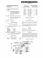
BRIEF DESCRIPTION OF THE DRAWINGS
40
Some ?eld devices include a transducer. A transducer is
understood to mean either a device that generates an output
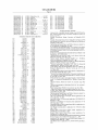
FIG. 1 is a diagrammatic vieW of an exemplary ?eld device
With Which the Wireless poWer and communication unit in
signal based on a physical input or that generates a physical
output based on an input signal. Typically, a transducer trans
forms an input into an output having a different form. Types of
accordance With the present invention is particularly useful.
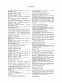
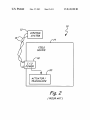
FIG. 2 is a block diagram of the ?eld device shoWn in FIG.
45
1.
transducers include various analytical equipment, pressure
sensors, thermistors, thermocouples, strain gauges, ?oW
FIG. 3 is a block diagram of a ?eld device including Wire
less communication circuitry for communicating With a
transmitters, positioners, actuators, solenoids, indicator
remote device such as a display or hand held unit.
FIG. 4 is a front elevation vieW of a Wireless poWer and
lights, and others.
Typically, each ?eld device also includes communication
50
circuitry that is used for communicating With a process con
trol room, or other circuitry, over a process control loop. In
some installations, the process control loop is also used to
deliver a regulated current and/ or voltage to the ?eld device
for poWering the ?eld device.
Traditionally, analog ?eld devices have been connected to
the control room by tWo-Wire process control current loops,
munication unit in accordance With embodiments of the
present invention.
55
With each device connected to the control room by a single
tWo-Wire control loop. Typically, a voltage differential is
maintained betWeen the tWo Wires Within a range of voltages
under the control of the control room by controlling the mag
nitude of the current through the loop. In addition to, or in the
FIG. 5B is a block diagram of an energy conversion module
in accordance With an embodiment of the present invention.
FIG. 6 is a diagrammatic vieW of an electrical poWer gen
eration system for a process device in accordance With an
embodiment of the present invention.
60
from 12-45 volts for analog mode and 9-50 volts for digital
mode. Some analog ?eld devices transmit a signal to the
control room by modulating the current running through the
current loop to a current proportional to the sensed process
variable. Other analog ?eld devices can perform an action
communication unit in accordance With embodiments of the
present invention mounted to a ?eld device.
FIG. 5A is a block diagram of a Wireless poWer and com
FIG. 7 is a diagrammatic vieW of a poWer generation sys
tem for process devices in accordance With an embodiment of
the present invention.
65
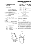
FIG. 8 is a diagrammatic vieW of a Wireless process device
in accordance With an embodiment of the present invention.
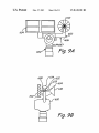
FIGS. 9A and 9B are front and side elevation vieWs,
respectively, of a process device in accordance With an
embodiment of the present invention.
US 8,145,180 B2
3
4
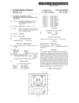
FIGS. 10A and 10B are front and side elevation vieWs,
respectively, of a process device in accordance With another
speci?c examples such as fuel cell and Wind-based generators
are provided later in the speci?cation. The poWer from mod
ule 38 energiZes controller 35 to interact With actuator/trans
embodiment of the present invention.
ducer 20 and Wireless communications module 32. Wireless
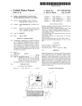
communications module 32, in turn, interacts With other
DETAILED DESCRIPTION OF THE PREFERRED
EMBODIMENTS
devices as indicated by reference numeral 24 via antenna 26.
FIG. 4 is a front elevation vieW of a Wireless poWer and
communication unit 100 attached to a ?eld device 14, shoWn
in phantom. Unit 100 preferably attaches to device 14 via a
standard ?eld device conduit 102. Examples of suitable con
The present invention provides electrical poWer generation
for ?eld devices using sources of energy that are located
proximate the ?eld device. Additionally, these sources of
energy do not rely upon solar energy. Embodiments of the
present invention include providing a Wireless poWer and
communication unit for alloWing ?eld devices that are
duit connections include l/2-14 NPT, M20><1.5, G1/2, and 3/8
18 NPT. Unit 100 may include a joint alloWing rotation 104
about axis 106 and rotation 108 about axis 110. Further,
attachment region 112 of unit 100 is preferably holloW in
order to alloW conductors therein to couple unit 100 to device
14. In embodiments Where positional adjustment of the hous
ing is not desired, attachment region 112 could simply be a
designed for Wired communication to operate Wirelessly.
Additionally, embodiments of the present invention include
generating poWer for a ?eld device using a non-solar source of
energy disposed proximate the ?eld device.
Embodiments of the present invention utiliZe a non-solar
energy source proximate the ?eld device in order to generate
poWer for use by the ?eld device. As used herein, the term
“non-solar” includes any source of poWer generated by mol
piece of conduit.
Unit 100 includes housing 114 that is mounted upon
20
scribed With respect to FIG. 8) to alloW unit 100 to poWer and
communicate With device 14 in accordance With a standard
ecules physically proximate the process device. Thus, non
solar energy can include Wind poWer, fuel cell technology that
makes use of oxygen proximate the ?eld device, and/or fuel
cell technology that makes use of molecules in the process
?uid itself for energy. Detailed descriptions of each of these
embodiments is set forth in greater detail beloW.
FIGS. 1 and 2 are diagrammatic and block diagram vieWs
industry protocol such as 4-20 mA, HART®, FOUNDA
TIONTM Fieldbus, Pro?bus-PA, Modbus, or CAN. Prefer
25
Since unit 100 is external to device 14, multiple variations
of unit 100 can be provided With varying internal poWer
30
control room or control system 12 that couples to one or more
?eld devices 14 over a tWo-Wire process control loop 16.
nication circuitry (not shoWn in FIG. 4) Which is coupled to
Examples of process control loop 16 include analog 4-20 mA
and digital communication such as the HighWay Addressable
Remote Transducer (HART®) standard, as Well as all-digital
protocols such as the FOUNDATIONTM Fieldbus standard.
Generally process control loop protocols can both poWer the
?eld device and alloW communication betWeen the ?eld
device and other devices.
In this example, ?eld device 14 includes circuitry 18
coupled to actuator/transducer 20 and to process control loop
16 via terminal board 21 in housing 23. Field device 14 is
illustrated as a process variable (PV) generator in that it
35
40
designed.
Unit 100 can also include a local user interface. Accord
45
local inputs such as button 124. A local user interface is
50
the unit, the ?eld device, orboth. As de?ned herein “local user
55
ate in the presence of vibration and/or electromagnetic inter
ference. Field devices of the sort illustrated in FIG. 1 repre
interface” means having either local user input(s) (such as a
button), local user output(s) (such as an LCD), or a combina
tion of the tWo. As illustrated in FIG. 4, the LCD can be
co-located With cell(s) 116.
sent a relatively large installed base of legacy devices, Which
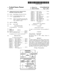
FIG. 5 is a block diagram of a Wireless poWer and commu
60
device 34 includes poWer generation module 38, controller
35, Wireless communication module 32, and actuator/trans
nication unit in accordance With embodiments of the present
invention. Unit 360 includes controller 362, poWer storage
device 364 (illustrated as a battery), energy converter 365,
loop communicator 368, and Wireless communication inter
face module 366.
ducer 20. Module 38 may include an internal poWer storage
ner in Which this generation occurs can take many forms and
important because When the combined unit/?eld device sys
tem is operating totally Wirelessly, it is more convenient for a
technician to interact With the local user interface rather than
Wirelessly trying to access the device via a handheld comput
ing device or the like. The local interface can be used to access
explosive atmospheres. Further, such devices must also oper
unit, and is adapted to poWer ?eld device 34. PoWer genera
tion module 38 generates electricity for device 34. The man
ingly unit 100 may include a display, such as an LCD display
122 that may be mounted proximate one of cells 116. In order
to receive local user input, unit 100 can include one or more
Generally ?eld devices are characterized by their ability to
are designed to operate in an entirely Wired manner.
FIG. 3 is a block diagram ofa Wireless ?eld device. Field
housing 114, or cell(s) 116 can be practiced as Well. External
antenna embodiments, hoWever, are particularly advanta
geous Where unit 100 is ?eld hardened in order to Withstand
environments similar to those for Which ?eld devices are
couples to a process and senses an aspect, such as tempera
operate in the “?eld” Which may expose them to environmen
tal stresses, such as temperature, humidity and pressure. In
addition to environmental stresses, ?eld devices must often
Withstand exposure to corrosive, haZardous and/or even
antenna 120. Providing external antenna 120 facilitates Wire
less communication in comparison to internal antennas since
many ?eld-hardened enclosures are metal and Would likely
attenuate the Wireless signal. HoWever, embodiments With an
internal antenna proximate a radio-transparent portion of
ture, pressure, pH, ?oW, or other physical properties of the
process and provides and indication thereof. Other examples
of ?eld devices include valves, actuators, controllers, and
displays.
generation modules depending upon the speci?c poWer
requirements of the ?eld device to Which the unit Will be
attached. Unit 100 also preferably includes Wireless commu
is useful. Process control or monitoring system 10 includes a
communication, hybrid protocols Which include both analog
ably, the protocol accommodates digital communication in
order to enhance the level of interaction betWeen unit 1 00 and
device 14.
of an exemplary ?eld device With Which a Wireless poWer and
communication unit in accordance With the present invention
attachment region 112. Housing 114 contains circuitry (de
65
Controller 362 preferably includes a loW-poWer micropro
cessor and appropriate charging circuitry to convey suitable
amounts of energy from cell(s) 116 and/or storage device 364
US 8,145,180 B2
5
6
to power unit 360 and any ?eld devices coupled to attachment
region 112. Additionally, controller 362 also directs excess
energy from cell(s) 116 and/or converter 365 to storage
device 364. Controller 362 can also be coupled to optional
temperature measurement circuitry such that controller 362
can reduce charging current to storage device 364 if device
364 begins to overheat. For example, the temperature mea
suring circuit may contain a suitable temperature-sensing
element, such as a thermocouple coupled to storage device
364. An analog-to-digital converter then converts the signal
(shoWn in FIG. 5B). Finally, in embodiments Where the poWer
storage device has a relatively large capacity in comparison to
the energy needs of the application, converter 365 may be
omitted. It is also expressly contemplated that combinations
of the various conversion modules illustrated in FIG. 5B can
be employed.
Wireless communication module 366 is coupled to con
troller 362 and interacts With external Wireless devices via
antenna 120 based upon commands and/or data from control
ler 362. Depending upon the application, Wireless communi
from the thermocouple to a digital representation thereof, and
provides the digital signal to controller 362.
Controller 362 can be con?gured, through hardWare, soft
cation module 366 may be adapted to communicate in accor
dance With any suitable Wireless communication protocol
including, but not limited to: Wireless networking technolo
gies (such as IEEE 802.11b Wireless access points and Wire
Ware, or both to actively manage poWer for itself and attached
?eld devices. In this regard, controller 362 can cause itself or
any desired ?eld devices to enter a loW-poWer sleep mode.
less netWorking devices built by Linksys of Irvine, Calif.),
Sleep mode is any operating mode Where poWer consumption
is reduced. With respect to ?eld devices, sleep mode could
result from commanding the ?eld device to set its operating
current at its loWest alloWable current rail. Events Which may
20
precipitate entering loW-poWer mode could include: the expi
ration of an activity period, an input from one or more of the
local user inputs, communication from one or more attached
?eld devices, or Wireless communication. Such events could
also be used to cause unit 360 and/or any attached ?eld
25
devices to aWaken from sleep mode. Additionally, controller
cellular or digital networking technologies (such as
Microburst® by Aeris Communications Inc. of San Jose,
Calif.), ultra Wide band, free space optics, Global System for
Mobile Communications (GSM), General Packet Radio Ser
vice (GPRS), Code Division Multiple Access (CDMA),
spread spectrum technology, infrared communications tech
niques, SMS (Short Messaging Service/text messaging), or
any other suitable Wireless technology. Further, knoWn data
collision technology canbe employed such that multiple units
can coexist Within Wireless operating rage of one another.
Such collision prevention can include using a number of
362 can selectively cause any attached ?eld device to enter
different radio-frequency channels and/or spread spectrum
sleep mode based upon any logic or rules contained in pro
gramming instructions Within controller 362 and/ or Wireless
communication received via Wireless communication mod
techniques.
Wireless communication module 366 can also include
30
transducers for a plurality of Wireless communication meth
ule 366. Preferably, local inputs, such as button 124 are user
ods. For example, primary Wireless communication could be
con?gurable. Thus a single button could be used to aWaken a
?eld device for a user-selectable period of time, and if so
con?gured, depressed again to cause the ?eld device to return
to sleep mode. In one embodiment, the con?gurable local
input button uses a jumper or sWitch to preset the folloWing
functions:
Button Depress Time to Activateiselect either 1, 1.5, 2 or
3 seconds. Field device ignores button presses having
durations shorter than the preset.
Unit On Timeiselect either 10, 15, 30 seconds, or 5, 15,
30, 60 minutes.
If the button is pressed tWice in close succession, the ?eld
device stays on for a preset period (for example 60
minutes) after Which it returns to sleep mode.
If the button is pressed a second time after a preset interval
(for example 5 seconds) the ?eld device Will return to
performed using relatively long distance communication
methods, such as GSM or GPRS, While a secondary, or addi
35
802.1 lb or Bluetooth.
Some Wireless communications modules may include cir
cuitry that can interact With the Global Positioning System
(GPS). GPS can be advantageously employed in unit 360 for
40
vice (GPRS) cell phone module, that has both a normal oper
ating mode and a sleep mode. A signal from controller 362
could cause module 366 to enter sleep mode When signi?cant
Wireless communication is not Warranted.
Energy converter 365 can be any device that is able to
generate electrical energy for use by the process device. Con
verter 365 can preferably include a generator (612) coupled to
a movable member such that environmental motion, such as
Waves or Wind generate electricity. Further, converter 365 can
include fuel cell 408. Further, converter 365 can employ
remote location. HoWever, location sensing based upon other
45
into electricity using compressed gas based generator 704
Memory 370 is illustrated in FIG. 5 as being separate from
controller 362, but may, in fact, be part of controller 362.
Memory 370 can be any suitable type of memory including
volatile memory (such as Random Access Memory), non
volatile memory (such as ?ash memory, EEPROM memory,
etc.) and any combination thereof. Memory 370 may contain
program instructions for controller 362 as Well as any suitable
50
administrative overhead data for unit 360. Memory 370 may
contain a unique identi?er for unit 360, such that unit 360 can
distinguish Wireless communications meant for it among
other Wireless communications. Examples of such an identi
55
Electronic Serial Number, global phone number, Internet
?er could include, a MediaAccess Controller (MAC) address,
Protocol (IP) address, or any other suitable identi?er. More
over, memory 370 may include information about attached
?eld devices, such as their unique identi?ers, con?gurations,
and abilities. Finally, controller 362, using memory 370 can
60
cause the output of unit 360 to be provided in any suitable
form. For example, con?guration and interaction With unit
360 and/or one or more associated ?eld devices could be
provided as HyperText Markup Language (HTML) Web
thermopile devices 702 (shoWn in FIG. 5B) to generate elec
tricity from disparate temperatures using the Peltier Effect.
Further still, the process may provide a source of energy in the
form of compressed gas or the like, that could be transformed
mobile devices to alloW ?nding the individual unit 360 in a
techniques can be used as Well.
sleep mode.
Controller 362 can also preferably cause portions of cir
cuitry Within unit 360 or attached ?eld devices to enter sleep
mode. For example, Wireless communication module 366
may be a commercially available General Packet Radio Ser
tional communication method could be provided for techni
cians, or operators near the unit, using for example, IEEE
pages.
65
Clock 372 is illustrated as being coupled to controller 362,
but may also be part of controller 362. Clock 372 alloWs
controller 362 to provide enhanced operation. For example,
US 8,l45,180 B2
7
8
clock 372 can be used to time the periods set forth above With
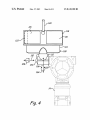
the heat generated by the exothermic reaction of fuel cell 408.
A source of liquid methane 412 is adapted to be stored in
compartment 404 on top of module 410. Liquid methane
storage system 412 is couplable to methanol fuel cell 408 via
respect to con?gurable button 125. Additionally, controller
362 can store information from one or more attached ?eld
devices, and correlate the information With time in order to
recognize trends. Further still, controller 362 can supplement
groove 414.
The ?rst fuel cells Were based on H2+O2QH2O+2ei Since
information received from one or more ?eld devices With time
information before transmitting it via Wireless communica
tion module 366. Further still, clock 372 can be used to
automatically generate periodic sleep/aWaken commands for
unit 360 and/or ?eld devices.Another form of periodic use for
clock 372 is to cause controller 362 to issue, via module 366,
a heartbeat type signal to periodically indicate an acceptable
10
Methanol is catalytically decomposed into H2+|biproducts| +
|heat. Atmospheric air is used as an oxygen (02) source. A
very signi?cant advantage of this type of fuel cell is its com
pact siZe. Small, methanol fuel cells based on micro-electro
mechanical systems (MEMS) technology can be built that are
capable of supplying adequate poWer for a Wireless process
status to an external Wireless device.
Loop communicator 368 is coupled to controller 362 and
interfaces controller 362 to one or more ?eld devices coupled
to one or more attachment regions 112. Loop communicator
368 is knoWn circuitry that generates appropriate signals in
order to communicate in accordance With an industry proto
col, such as those set forth above. In embodiments Where unit
360 is coupled to a plurality of ?eld devices that communicate
in accordance With different protocols, it is conceivable that
variable transmitter. Current state of the art for methanol fuel
cells indicates that a device roughly the siZe of a deck of cards
Would provide adequate fuel storage and electricity genera
20
connection(s) made through attachment region 112 alloWs
25
Wire loop. HoWever, it is also contemplated that embodiments
operating temperature. In embodiments Where the poWer sys
tem housing 400 is made of metal, this generated heat is
30
communication. For ease of technician access, unit 360 may
include tWo or more terminals proximate loop communicator
35
FIG. 5 also illustrates optional operator button block 374
and LCD display block 376 in phantom being coupled to
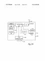
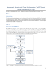
electrically coupled to methanol fuel cell 408 and receives
controller 362. This illustration is intended to shoW that all
40
from electronics module 410 via thermal barrier 406. Metha
nol storage 412 is coupled to methanol fuel cell 408 via
electrically controlled valve 422. Valve 422 receives its con
trol signal from a fuel-on output line 424 from module 410.
to interact With each local display individually based upon
inputs from the ?eld device, the con?gurable button associ
Electricity generated in fuel cell 408 is provided through line
ated With the ?eld device, one or more buttons or inputs
disposed proximate unit 360, or from Wireless communica
50
eration system for a process device in accordance With an
embodiment of the present invention. System 360 is illus
trated as being an external module to a process device, but can
also be manufactured to be integral With the process device.
Module 360 includes housing 400 that is couplable to the
process device. Housing 400 includes a pair of compartments
402, 404 that are separated by thermal barrier 406. A small
form factor methanol fuel cell 408 is placed in compartment
402. Electronics control and poWer management system 410
includes a number of poWer management components and
circuits and is disposed in compartment 404. Electronics
module 410 may include an ultra high capacity capacitor,
and/ or battery to handle peak transmission poWer demands.
55
tronics module 410 is also preferably encapsulated in order to
further thermally isolate the electronics in module 410 from
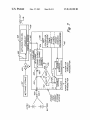
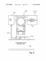
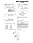
420 to charge and control circuit 426. Charge and control
circuit 426 provides an output 428 through diode 430 that is
arranged to ensure that energy does not How back thorough
fuel cell 408. If an additional energy storage unit is provided,
it is coupled to Vow line 432. The voltage at node 434 is
compared, using preferably a comparator, With a minimum
threshold voltage. If the voltage at node 434 is less than the
minimum threshold voltage, then charging is enabled via line
436. If, hoWever, the voltage at node 434 is greater than the
minimum threshold, then a signal is provided along line 438
to enable poWer for the process variable transmitter as Well as
poWer for the Wireless communicator. Accordingly, if insuf
?cient poWer is available from the methanol based fuel cell to
run the process variable transmitter and/or the Wireless trans
mitter, then the poWer circuit focuses upon storing enough
Additional details regarding the actual circuit employed in
module 410 that are provided With respect to FIG. 7. Elec
poWer therefrom via line 420. Methanol based fuel cell is
disposed Within compartment 402 that is thermally isolated
poWer and communication unit 360, or both are coupled to
controller 362. Additionally, local user displays, on each ?eld
device, Wireless poWer and communication unit 360, or both
are also coupled to controller 362. This alloWs controller 362
tion.
FIG. 6 is a diagrammatic vieW of an electrical poWer gen
provided as an alternative embodiment.
FIG. 7 is a diagrammatic vieW of the poWer generation
system for process devices in accordance With an embodi
ment of the present invention. Electronics module 410 is
Prairie, Minn.
local inputs, be they on individual ?eld devices, Wireless
dissipated by both convection and radiation. Additionally,
thermal barrier 406 helps protect electronics 410. Housing
400 also includes a vent 418 to alloW atmospheric oxygen to
interact With cell 408. In embodiments Where venting may be
objectionable, a miniature fan in a small, sealed duct can be
368 or attachment region 112 in order to facilitate the cou
pling of a handheld con?guration device, such as the Model
375 Handheld device available from Rosemount, Inc. of Eden
416 is disposed on top of housing 400 to release heat gener
ated by cell 408. It is important to ensure that the heat gener
ated by the catalytic decomposition of methanol is dissipated
and prevented from heating electronics 410 beyond their safe
the same conductors used for communication, such as a tWo
of the invention can be practiced Where poWer is provided to
the ?eld device on separate conductors than those used for
tion for the Wireless process variable ?eld device.
Since the catalytic decomposition of methanol generates
heat, cell 408 is separated thermally from electronics 410 and
liquid storage tank 412. Additionally, a heat dissipating cover
multiple loop communicators could be used to alloW control
ler 362 to interact With the various ?eld devices. The physical
unit 360 to poWer and communicate With the ?eld devices. In
some embodiments, this can be done by providing poWer over
H2 is dif?cult to store and is dangerous to handle, alternate
fuel cell strategies Were investigated. One attractive fuel cell
technology is that based on the methanol fuel cell. Methanol
fuel cells are currently knoWn and can be built practically.
65
energy to run either the process variable transmitter or the
Wireless communicator at some later time. FIG. 7 also illus
trates a unit controller and sleep mode timer 438 that gener
ates an enable signal sent to the process variable transmitter
and the Wireless communicator. Thus, unit controller and
sleep mode timer 438 can cause the process variable trans