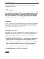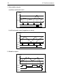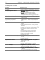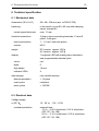
1
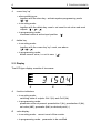
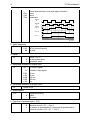
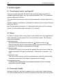
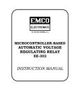
Programmable Preselect Counter GEL 104 User Manual P1 P2 SET PSC F1 F2 LENORD, BAUER & CO. GMBH, 04/99 MO T O R T E C H N O L O G Y L T D MOTEC HOUSE, CHADKIRK BUSINESS PARK, STOCKPORT, CHESHIRE SK6 3NE ENGLAND Subject to change without notice TELEPHONE: +44 (0)161 217 7100 FAX: +44 (0)161 217 7101 E-MAIL: [email protected] WEB SITE: www.motec.co.uk Lenord, Bauer & Co. GmbH Dohlenstraße 32 D - 46 145 Oberhausen Phone +49 - 208 - 99 63 - 0 • Fax +49 - 208 - 67 62 92 Internet: http://www.lenord.de • E-Mail: [email protected] OPERATOR'S MANUAL G E L 1 0 4 C o n t e n t s 1 Introduction ................................................................................................ 1 1.1 1.2 1.3 Fundamental safety instructions.............................................................1 Designated use ......................................................................................2 Guarantee, liability and copyright ...........................................................2 2 Control elements........................................................................................ 3 2.1 2.2 Keyboard ................................................................................................3 Display....................................................................................................4 3 Programming.............................................................................................. 5 3.1 3.1.1 3.1.2 3.2 3.2.1 3.2.2 3.3 Operating parameters ............................................................................5 Preselections 1 (P1) and 2 (P2) .............................................................6 Set value (SET) ......................................................................................6 Display parameters ................................................................................6 Prescaler (PSC) .....................................................................................6 Decimal point..........................................................................................7 System parameters ................................................................................7 4 Control signals ......................................................................................... 10 4.1 4.2 4.3 4.4 4.5 4.6 Count inputs Input A and Input B ........................................................10 Reset ....................................................................................................10 Count gate Inhibit ................................................................................10 Display Hold .........................................................................................11 Keylock .................................................................................................11 Outputs Out 1, Out 2 ............................................................................11 5 Assembly, commissioning, diagnosis of errors ................................... 13 5.1 5.2 5.3 Assembly instructions...........................................................................13 Commissioning.....................................................................................13 Diagnosis of errors ...............................................................................14 6 Technical specification ........................................................................... 15 6.1 6.2 6.3 6.4 6.5 Mechanical data ...................................................................................15 Electrical data.......................................................................................15 Environmental conditions .....................................................................17 Type code.............................................................................................17 Dimensions...........................................................................................18 7 Pin layout .................................................................................................. 19 1 INTRODUCTION 1 1 Introduction 1.1 Fundamental safety instructions ▲ The programmable preselect counters type GEL 104 have been built in accordance with state-of-the-art standards and the recognised safety regulations. Nevertheless, its use may constitute a risk to life and limb of the user or of third parties, or cause damage to the counter or to other components property. The counters must only be used − in accordance with their designated use − in technically perfect condition. In order to maintain this status and to ensure a safe operation of the counters, only skilled personnel1 are allowed to commission, connect and service these components, while observing the current regulations for prevention of accidents and safety instructions as well as the operating instructions. ▲ If a break down or malfunctioning of the counter may cause injury or damage works equipment, this must be prevented by taking additional safety measures, such as, for example, installation of limit switches, protective devices, etc. ▲ If a safe operation can no longer be ensured, the counter must be stopped and secured against unintentional operation. ▲ When mounting and connecting, the counter and all other components concerned, must be de-energised: voltages up to 250 VAC may occur! Make sure that meanwhile the line cannot be switched on. ▲ To ensure the hand contact safety (VDE 0106) of the connecting terminals a professional connection of the current-carrying cables is required. Terminals not being assigned ('NC') must not be wired-up. ▲ The counter must only be repaired by LENORD+BAUER or a company/person authorised by LENORD+BAUER. 1 Skilled personnel does mean: − persons being familiar with the safety principles of automation systems, − persons being trained on commissioning and servicing, − persons knowing how to operate the device and knowing the relevant instructions in the manual which are vital for the proper functioning of the device. 2 1 INTRODUCTION 1.2 Designated use The GEL 104-type counters have been exclusively built for measuring and controlling purposes in industry. In conjunction with an incremental pulse generator, e.g. positions, lengths or angles may be measured and displayed or cutting and dosing jobs may be performed. The counters should not be put into operation unless being built in. Designated use also means that the user follows all instructions given in this manual. Using the device for purposes other than those mentioned above is considered contrary to its designated use. LENORD, BAUER & CO. GMBH cannot be held liable for any damage resulting from such use. 1.3 Guarantee, liability and copyright In principle, our general 'Terms of delivery and payment' apply which are part of the sales contract and are made available to the Buyer upon signing of the contract at the latest. LENORD, BAUER & CO. GMBH will not accept any claim under guarantee nor any other responsibility in case of injury to persons or damages, if they are due to one or several of the following reasons: • non-designated use of the counter • improper mounting, commissioning and operation of the counter • operation of the counter when the safety devices of the line are defective or not operative • non-observance of the instructions supplied in the manual regarding storage, assembly, commissioning and operation of the counter • unauthorised modifications of the counter's design • improper repair • disasters caused by foreign objects and Force Majeure This manual was prepared with utmost care. We do, however, not assume any liability with regard to faultlessness. LENORD+BAUER hold the copyright of this operating manual. The manual is only intended for the buyer or the machine builder and their personnel. All instructions, notes and other data supplied must not be copied, distributed or communicated neither partially nor entirely. Violations might be prosecuted. 2 CONTROL ELEMENTS 3 2 Control elements 2.1 Keyboard The function of these five keys depends on the current mode of operation of the counter. 1 1 F1 F2 2 3 4 5 X1104055 store key • in counting mode: in conjunction with another key only: start programming mode (see further below) • in programming mode: save last entry and − terminate programming mode or − selection of subsequent parameter (depending on the programming plane) 2 sign key • in counting mode: − programming of the 1st preset value P1 (F1) − together with the store key: programming the set value SET ( F1) • in programming mode: change sign ( ) 3 cursor key 'left' • in counting mode: − programming of the 2nd preset value P2 (F2) − together with the store key: programming of a prescaler PSC (prescaler) or decimal point ( + F2) • in programming mode: activate next input position of a value ( ) + 4 4 2 CONTROL ELEMENTS cursor key 'up' • when switching on: together with the store key: activate system programming mode ( + ) • in counting mode: together with the delete key: reset = set count to set value and reset outputs ( + = ) • in programming mode: increment value at active input position 5 ( ) delete key • in counting mode: together with the cursor key 'up': reset, see above ( + = ) • in programming mode: delete current value, i.e. set to zero ( ) 2.2 Display The LED-type display consists of two areas: P1 P2 SET PSC A A B X1104022 function indicators • in counting mode: switching state of outputs Out 1 (P1) and Out 2 (P2) • in programming mode: parameter active at present: preselection 1(P1), preselection 2 (P2), set value (SET), prescaler (PSC) or decimal point (–) B value display • in counting mode: current count of the counter • in programming mode: parameter to be modified 3 PROGRAMMING 5 3 Programming Several programming planes are available for programming the counter. Via the 1st programming plane the user is provided with access to the operating parameters, i.e. preselection 1 / 2 and set value, which are frequently changed. In the second programming plane the display parameters, the prescaler and the decimal point can be set. Access to the operating and display parameters can be locked by means of the control input Keylock (terminal 28). In the third programming plane the general mode of operation of the counter and all plant or machine relevant system parameters will be fixed. Normally, this is only necessary on commissioning or after a retrofit. 3.1 Operating parameters Enter this programming plane by a short pressing of a certain key or key combination (see below). The active parameter is indicated by flashing of the respective indicator (P1, P2 or SET) and the lowest digit of the pertaining value. To return to the counting mode either − press the store key or − it is carried out automatically approx. 15 seconds after actuation of a key (without saving a modified value). Programming is performed as follows: • if required, cancel a value using the delete key (you may only erase an entire value, i.e. you may not erase it digit by digit) • use the cursor key to go to position of the value to be changed (the activated digit flashes) • use the cursor key to increment the figure concerned • modify all remaining digits of the value as described above • in case of a negative value press the operational sign key • save value by pressing the key 6 3 PROGRAMMING 3.1.1 Preselections 1 (P1) and 2 (P2) Key: F1 for preselection 1 (P1) F2 for preselection 2 (P2) P1 may be interpreted either as absolute or relative value (see para. 3.3, system parameter F20). P2 is the main preselection by means of which an automatic reset is initiated in the counter, provided that it had been programmed accordingly (see para. 3.3, system parameters F4). As soon as the count reaches the programmed value of P1 or P2 (via counting pulses counted upwards or downwards), the respective relay switch Out 1 or Out 2 (Out 1 is reset by P2). 3.1.2 Set value (SET) Key: + F1 In case of a reset the count of the counter will be set to this value (via keyboard, terminal or automatically). 3.2 Display parameters Key: + F2 The parameter last modified is the active one: prescaler (prescaler, indicator PSC) or decimal point. By briefly pressing the store key you may switch back and forth between the two parameters. To return to the counting mode either − press the store key longer than 2 seconds or − it is performed automatically approx. 15 seconds after having last actuated any key (modified parameters will not be saved) A reset is always performed. 3.2.1 Prescaler (PSC) Values must be entered as described in para. 3.1. By means of the prescaler the number of counting pulses (= encoder pulses ∗ edge evaluation) may be converted in such a way, that the count will be displayed in the required unit. A residual value processing is not performed. 3 PROGRAMMING 7 Setting range: 0.0005 … 99.9999 (standard setting: 1.0000) If you enter a value less than 0.0005 the error message Error0 will be emitted. To enter a new value press the store key. 3.2.2 Decimal point Use the cursor key –. –.– –.–– –.––– to select one of the 4 possible variants: = = = = display without decimal point display with one decimal display with two decimals display with three decimals 3.3 System parameters To enter this operating plane press the store key and the cursor key simultaneously upon switching on the supply voltage. The following parameters and their variants are available (standard settings are printed in boldface): Parameter Variant Description 1. Count inputs A, B In dIF A, B as differential inputs: A accumulative, B subtractive Input A + 1 Input B - 1 0 0 1 Count 0 -1 E110401A ud A is the count input, B is the counting direction input (up/down) Input A 1 Input B 1 count pulses 0 up/down 0 1 Count 0 -1 E110401B 8 3 PROGRAMMING Ph1 Ph2 Ph4 phase discriminator mode with edge evaluation once, twice, quadruple Input A 1 90° 0 Input B 1 Count 0 8 5 0° eval.: x4 eval.: x2 eval.: x1 0 5 0 5 0 up down E110401C 2. Input frequency Fr 0.03 40 input damping 30 Hz (bounce-proof), 40 kHz 3. Mode F4 0 1 count = P2 ⇒ no automatic reset automatic reset 4. Switching duration of output Out 1 F5 oFF bI 0.02 0.05 0.10 0.50 1.00 no output signal bistable output signal 20 ms 50 ms 100 ms 500 ms 1s 5. Switching duration of output Out 2 F6 same as F5 6. Reset-signal F13 0 1 signal processing static, dynamic 7. Function of preselection 1 (P1) F20 0 1 value is effective absolute (count = P1 → Out 1), in relation to preselection 2 (presignal for preselection 2, count of counter = P2 + P1 → Out 1) 3 PROGRAMMING 9 8. Output signal memory F21 0 outputs reset after having switched on the power supply 1 same switching status as prior to switching on the power supply, monostable times, however, being started anew 9. Input signal level F24 0 npn: active level: Low 1 pnp: active level: High 10. Lock keyboard reset F26 0 1 if the signal Keylock is active, the keyboard reset is not locked, locked 11. Programming lock for the set value F27 0 1 if the Keylock signal is active, the key combination is unlocked, locked + F1 12. Programming lock for display parameters F28 0 1 if the Keylock signal is active, the key combination is not locked, locked + F2 13. Programming lock for preselection F29 0 1 2 3 if the Keylock signal is active, the key(s) F1 and F2 are not locked F1 is locked (preselection P1) F2 is locked (preselection P2) F1 and F2 are locked (both preselections) 14. Standard settings F30 0 no function 1 all parameters are set to standard (upon pressing the store key) Use the cursor key to select the requested option and confirm by pressing the key; thus the subsequent parameter will be automatically activated. To return to the counting mode longer than 2 seconds or − press the store key − this is performed automatically approx. 40 seconds after having last actuated any key (modified parameters will not be saved). 10 4 CONTROL SIGNALS 4 Control signals 4.1 Count inputs Input A and Input B The count inputs (terminals 30 and 29) are controlled with the positive or negative signal edge (pnp / npn, see system parameter F24). The maximum counter frequency is 40 kHz. You may use all commercial electronic pulse generators, whose High level is > 8 V. Signals emitted by mechanical, potential-free switches are processed (bouncefree, max. 30 Hz). Use the first system parameter ‘In’ to determine the function of the counting inputs, i.e. the counting mode (see para. 3.3, 1st point). 4.2 Reset If a reset is carried out the count of the counter will be set to the programmed value (standard: 0) and outputs Out 1 and Out 2 will be reset. The following options are available: a) keyboard reset By simultaneously pressing the delete key and the cursor key (can be locked by means of the Keylock signal, provided that the system parameter F26 had been programmed accordingly) b) terminal reset At terminal 26 High or Low level will be applied (the active level is fixed via system parameter F24 and its processing – either static or dynamic – via F13) c) automatic reset The count of the counter reaches the preselection value P2 (provided that the system parameter F4 had been programmed accordingly) d) programming reset is effected when leaving the 2nd programming plane where the display parameters can be changed. 4.3 Count gate Inhibit As long as High (or Low) level is applied to the control input Inhibit (terminal 25), both counting inputs are locked (to determine the active level use system 4 CONTROL SIGNALS 11 parameter F24). Thus you can interrupt the counting mode, although the counting pulses continue. 4.4 Display Hold As long as High (or Low) level is applied to the control input Hold (terminal 27), the current count of the counter is 'frozen' without loosing any pulse (the active level is fixed by system parameter F24); when changing the level the current count will be shown again. Thus, especially where rapid counting operations are concerned, the counter can comfortabely be read at any time without having to interrupt the current counting operation. 4.5 Keylock As long as High (or Low) level is applied to the control input Keylock (terminal 28) (use system parameter F24 to determine the level), certain programming planes cannot be activated and/or a keyboard reset cannot be carried out. (depending on system parameters F26 … F29). 4.6 Outputs Out 1, Out 2 The outputs Out 1 and Out 2 are available as transistor outputs (pnp) and as potential-free change-over contacts. To protect the counter against harmful voltage spikes we recommend external measures for spark prevention. Some fundamental characteristics are: • The outputs can be locked individually or can be switched to monostable or bistable operation; for this purpose use system parameters F5 and F6. • The switching status prevailing prior to switching off the voltage supply may be reactivated upon switching on, provided that system parameter F21 had been programmed accordingly; monostable times will be started anew. • As soon as the count has reached the preselection P2, Out 1 will be reset; the same also applies to the count provided that system parameter F4 has been programmed accordingly (automatic reset). • If a reset is performed Out 1 and Out 2 will be reset. Examples: 12 4 CONTROL SIGNALS 1. Monostable outputs a) without automatic reset Count P2 P1 Out 2 t E110401D b) with automatic reset (negative set value) Count P2 P1 0 SET t Out 1 Out 2 E110401E 2. Bistable outputs Count P2 P1 t Out 1 Out 2 Reset E110401F 5 ASSEMBLY, COMMISSIONING, DIAGNOSIS OF ERRORS 13 5 Assembly, commissioning, diagnosis of errors 5.1 Assembly instructions 1. Before incorporating the counter into the control panel the installation frame (see dimensioned drawing in chapter 6) must be pulled off the counter housing. For this purpose slightly lift the 4 catch brackets (alternately on top and at the bottom, and pushing them forward catch by catch). 2. Turn back the screws of the installation frame by approx. 5 mm. 3. Insert counter into the cut-out of panel and snap installation frame into place. 4. Fix the counter with the screws against the panel (free from play). 5.2 Commissioning Before setting the counter into operation check whether you can answer the following questions with yes: ✔ Does the supply voltage rating correspond to the voltage specified at the counter? ✔ Has the supply voltage been connected to the correct terminals and is the polarity correct for DC supply? ✔ The maximum counter frequency will not be exceeded? ✔ Have the control pulses for the counter got the necessary switching thresholds (see para. 6.2)? ✔ Has programming been performed properly, i.e. according to the specific requirements? 14 5 ASSEMBLY, COMMISSIONING, DIAGNOSIS OF ERRORS 5.3 Diagnosis of errors Problem Possible cause no display • supply voltage OFF or improperly connected all display segments are ON • short-time: self-test after having switched on the supply voltage • sporadic: contact of supply voltage connections not in perfect condition or voltage fluctuates under the minimum value keyboard reset not possible • locked (system parameter F26) and signal Keylock active input of preselection or other programming not possible • programming lock(s) switched on (system parameter F27 … F29) and signal Keylock active counter does not count • counting input not connected properly or bridged • earth connection counter – pulse generator defective • incorrect level (npn/pnp, system param. F24) • contact/pulse generator does not switch properly • max. counting frequency is exceeded • input Reset, Hold or Inhibit activated • pulse or pause width too small • prescaler too small counter does not count correctly • bounce/disturbing pulses, vibrations at the encoder • incorrect prescaler outputs without function • signal duration programmed "off" (system parameter F5 or F6) • faulty relay • contacts welded because of overload Error0 message • programming of prescaler < 0.0005 confirm error message with the store key Error1 message • counted value limits exceeded (< -99 999, > 999 999) use keyboard reset to delete error message 6 TECHNICAL SPECIFICATION 15 6 Technical specification 6.1 Mechanical data dimensions (W × H × D) 96 × 48 × 108 mm (acc. to DIN 43 700) fastening in the panel cut-out 92 × 45 mm with clamping frame, screws M3 control panel thickness electrical connection max. 11 mm 2 plug-in-type connecting terminals, 10 and 8 poles, 5 mm grid lead cross section 1…1,5 mm2 with end splices screws M2.6 weight DC version: approx. 200 g AC version: approx. 420 g display 7-segment-LED with leading zero elimination and programmable decimal point colour red digits 6 digit height 14 mm indicator LEDs 4 data storage non-volatile memory data conservation > 10 years read cycles unlimited write cycles > 100 000 6.2 Electrical data Voltage supply a) DC Ub overload protection 12…24 V= -5% / +10% external fuse: 12 V= : 0.25 A fast-blow / 0.25 A slow-blow (IEC 127 / UL 198) 24 V= : 0.16 A slow-blow / 0.20 A slow-blow (IEC 127 / UL 198) 16 6 TECHNICAL SPECIFICATION peak current consumption max. 300 mA (incl. 60 mA encoder current) power consumption b) AC overload protection current consumption circuit interruption max. 4.5 W (worst case) 115 / 230 VAC -10% / +6%, 50…60 Hz external fuse: 115 VAC : 63 mA slow-blow 230 VAC : 32 mA slow-blow typ. 50 / 25 mA (incl. encoder supply) 1 half-wave acc. to IEC 127-2 counting and control inputs switch level Low: ≤ 2 V; High: ≥ 8 V amplitude max. ±40 V switch edge pnp / npn (programmable) pulse shape any input resistance approx. 5 kΩ count gate Inhibit (term. 25) static min. pulse duration 12 µs (damped 17 ms) Reset (terminal 26) min. pulse width display Hold (terminal 27) static or dynamic (programmable) 2 ms (damped 17 ms) static min. pulse width 3 ms Keylock (terminal 28) static min. pulse width 3 ms count inputs Input A, Input B (terminals 29 and 30) frequency max. 40 kHz (in case of square wave 1:1 with amplitude > 10 V and phase error of max. ±20°); max. 30 Hz (bounce-proof) pulse width min. 12,5 µs (damped min. 17 ms) 6 TECHNICAL SPECIFICATION 17 Outputs encoder supply (terminals 31, 32) max. current relay Out 1, Out 2 DC type: Ub - 2 V AC type: 12…24 VDC 60 mA change-over contact contact protection none; recommended to be provided externally in case of capacitive and inductive loads switching voltage 5 VAC/DC … 30 VDC / 250 VAC switching current 10 mA … 1 A transistor Out 1, Out 2 pnp switching voltage DC version: Ub - 2 V; AC version: 24 VDC switching current max. 10 mA operate lag max. 10 ms 6.3 Environmental conditions operating temperature 0 °C … + 50 °C storing temperature -20 °C … + 70 °C protection class (IEC 144) front: IP54 connecting side: IP20 electromagnetic immunity (EMC, IEC 801, P2 + P4) DC version: severity 3 AC version: severity 2 resistance to vibrations 10 m/s2 (10…150 Hz) acc. to IEC 68, P2-4 resistance to thermal shocks 100 m/s2 (18 ms) acc. to IEC 68, P2-27 design according to DIN 57411 / VDE 0411, protection class II ambient conds. (DIN 40 040) 40°C / 92% relative humidity of air contamination level 2 acc. to VDE 0110 6.4 Type code GEL 104.1 GEL 104.2 DC operating voltage 12 ... 24 VDC AC operating voltage 115 / 230 VAC 18 6 TECHNICAL SPECIFICATION 6.5 Dimensions 8 clamping frame 48 plug-in terminals 96 108 45 Panel Cutout mm 92 E1104084 7 PIN LAYOUT 19 7 Pin layout DC version AC version L 230 V~ 1 2 3 4 5 6 7 8 9 10 11 12 13 14 15 16 N 63 mA T 115 V~ 32 mA T L 0V +Ub: 12...24 V= NC NC N [m]A T: slow-blow [m]A F: fast-blow NC Out1 30 V=/1 A, 250 V~/1 A (max. 250 V related to earth) NC Out2 30 V=/1A, 250 V~/1 A (max. 250 V related to earth) NC Out1 (Transistor: UO/10 mA) Out2 (Transistor: UO/10 mA) 0V pnp 25 26 27 28 29 30 31 32 0.25 A F (12 V), 0.16 A T (24 V) IEC 127 0.25 A T (12 V), 0.20 A T (24 V) UL 198 npn Inhibit Reset Hold Keylock Input B Input A 0V Encoder supply: UO/ 60 mA AC version: UO = 12...24 VDC DC version: UO = Ub - 2 V E1104025 Note: The DC type has no galvanic isolation between the voltage supply and the electronic inputs and outputs!