1
Translation of the original instructions
Electrospindle
ES748, ES750
User Manual
Edition.Revision 1.1
H5801H0083 ENGLISH
Serial number
Information about the publication
Information about the publication
Code
Issue
H5801H0083
1
Revision
Description of updates
0 (11/2011)
new document
1 (06/2012)
General revision
Code of previous issue
This manual has been prepared for use by customers only, and contains information protected by
copyright. It must not be photocopied or reproduced in any form, either fully or in part, without the
prior written consent of the manufacturer.
HSD S.p.A. © - H5801H0083.fm051112
3
Information about the publication
4
HSD S.p.A. © - H5801H0083.fm051112
Index
Index
1
Preliminary information
1.1
1.2
1.3
1.4
1.5
1.6
1.7
2
Technical Specifications
2.1
2.2
2.3
3
Description of main parts: ES748 .................................................................................... 13
Description of main parts: ES750 ..................................................................................... 14
Characteristics and performance ..................................................................................... 16
Transport, packing, unpacking, storage
3.1
3.2
3.3
3.4
3.5
4
Documents supplied with the product ................................................................................ 7
Scope of the manual .......................................................................................................... 7
Symbols used in the manual .............................................................................................. 8
Risks associated with the use of the product ..................................................................... 8
Product Information .......................................................................................................... 10
Glossary .......................................................................................................................... 11
Warranty ........................................................................................................................... 12
Warnings ..........................................................................................................................
Dimensions and weights ..................................................................................................
Transport and packing conditions ....................................................................................
Unpacking ........................................................................................................................
Storage ............................................................................................................................
21
21
21
22
23
Installation and commissioning
4.1
4.2
4.3
4.4
4.5
4.6
4.7
4.8
4.9
4.10
4.11
4.12
Preliminary installation checks .........................................................................................
Preparing the factory services ..........................................................................................
Mechanical connections ...................................................................................................
Specifications for the compressed air supplied to the manufacturer's products ..............
Example diagrams for pneumatic circuits by the customer ..............................................
ES748 and ES750 connections for air cylinder ...............................................................
ES750 connections for Oil cylinder ................................................................................
Internal pressurisation ......................................................................................................
Refrigerator ......................................................................................................................
Tool cooling ......................................................................................................................
Example diagram of the cone's cleaning circuit ...............................................................
Electrical connections ......................................................................................................
HSD S.p.A. © - H5801H0083TOC.fm051112
25
25
26
27
29
31
32
32
33
34
35
36
5
Index
5
General post-installation checks
5.1
5.2
6
Use and adjustment
6.1
6.2
6.3
6.4
6.5
6.6
6.7
6.8
6.9
6.10
7
Environmental conditions .................................................................................................
Running-in ........................................................................................................................
Warm-up ..........................................................................................................................
Collet ................................................................................................................................
Tool holder cone ...............................................................................................................
Tool ..................................................................................................................................
Fluids distributor ...............................................................................................................
Procedure to follow if the tool becomes jammed in the piece being machined ...............
Sensors ............................................................................................................................
Encoder ............................................................................................................................
Daily maintenance ........................................................................................................... 62
Biweekly maintenance ..................................................................................................... 64
Bearings ........................................................................................................................... 64
Replacing components
8.1
Replacement and adjustment of the sensor unit .............................................................. 66
9
Disposal of the product
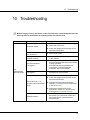
10
Troubleshooting
11
List of spare parts
12
Assistance
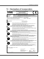
13
Declaration of incorporation
6
43
43
43
44
44
45
46
47
48
52
Programmed maintenance
7.1
7.2
7.3
8
Electrospindle pre-startup checks .................................................................................... 39
First start-up checks ......................................................................................................... 41
HSD S.p.A. © - H5801H0083TOC.fm051112
1 Preliminary information
1
Preliminary information
1.1
Documents supplied with the product
The following documents are supplied together with the product:
Declaration of incorporation as provided for by Appendix IIB of Directive 2006/42/EC
Product test certificate
This manual, containing warnings and instructions for the transport, installation, use,
maintenance and disposal of the product
Check that all the documents listed above are present on delivery of the product. If
necessary, further copies can be obtained on request from the manufacturer.
1.2
Scope of the manual
The manual forms an integral part of the product and as such must accompany it at all times,
otherwise the product will be lacking in one of its primary safety requirements.
The manual must be well taken care of, distributed and made available to all personnel involved.
The purpose of the warnings contained in the manual is to safeguard the health and safety of
personnel exposed to residual risks.
The manual provides information on the most appropriate behaviour to adopt for the correct use of
the product as provided for by the manufacturer.
In the case where the information contained in the manual conflicts with health and safety
standards, contact the manufacturer to request the necessary corrections and/or adaptations.
In order to prevent incorrect operation that could constitute a hazard for personnel and/or cause
damage to the product, all the documents supplied with the product must be read and fully
understood.
The manual must be stored in an appropriate location and must always be readily available for
consultation.
The information contained in the manual is indispensable for using the product in a safe and
correct manner for the purposes for which it has been designed.
HSD S.p.A. © - 0101h00a.fm051112
7
1 Preliminary information
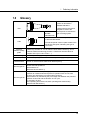
1.3
Symbols used in the manual
Danger
Indicates a procedure, practice or similar action that could cause injury if not
respected or carried out correctly.
Caution
Indicates an operating procedure, practice or similar action that could damage or
completely destroy the product if not respected or carried out correctly.
Information
Highlights particularly important information of a general nature that must not be ignored.
1.4
Risks associated with the use of the product
The manufacturer is not aware and cannot be aware of how the product will be installed.
Consequently, the installer or final user must perform a risk analysis relating specifically to the type
of installation and the methods adopted.
It is nevertheless the responsibility of the installer to ensure that there is adequate protection
against risks of accidental contact with moving parts.
The installer and user must also take into account the possible presence of other types of risk, in
particular that deriving from the entry of foreign bodies and the use of explosive, flammable, toxic
or hot gases.
Consideration should also be given to risks inherent to maintenance operations, which must be
carried out under conditions of maximum safety by ensuring that the product is isolated and at a
complete standstill.
An overall risk analysis must be carried out on the completed machine on which the
manufacturer's product will be installed. A conformity declaration must then be issued in line with
Appendix IIA of directive 2006/42/EC and its subsequent amendments.
The product must not be put into service until the machine in which it has been incorporated has
been made to comply with the requirements of Directive 2006/42/EC and its subsequent
amendments.
1.4.1
Risks associated with improper handling and/or use
It is absolutely forbidden to bypass, remove, modify or render inoperative any safety devices,
controls or guards protecting individual parts or the product as a whole.
Never place hands, arms or any other parts of the body near to moving parts.
The product must not be used in environments where there is an explosion risk .
The elimination of faults or anomalies in the operation of the product or modifications to the
type of operation or installation must not be carried out by unauthorised personnel.
8
HSD S.p.A. © - 0101h00a.fm051112
1 Preliminary information
On completion of any extraordinary maintenance involving the removal of guards, barriers or
other safety devices, these must be replaced before starting the product, making sure that
they are positioned correctly and in full working order.
All guards and safety devices must be maintained efficient and in perfect condition. Warning
and danger signs and symbols must be clearly legible and must never be removed.
When performing troubleshooting operation on the product, take all the necessary precautions
described in the Instruction Manual to prevent damage or injury.
Remember to tighten all screws, nuts and locking rings of each mechanical component that
has been adjusted or set-up.
Before starting the product, make sure that all the safety devices are installed and in perfect
working order. If this is not the case, under no circumstances must the product be started,
instead inform the works safety manager or the department head.
The operator must be provided with Personal Protection Equipment (PPE) as provided for by
current legislation. Loose bulky clothing and accessories (ties, wide sleeves, etc.) must not be
worn
1.4.2
Risks specific to product maintenance
In order to be able to work in complete safety on a product already installed on a
machine, refer to the machine's instruction manual.
Isolate the product from the mains power supply before proceeding with any maintenance
operations!
Even though the product has been disconnected from the mains power supply, the rotating
and mobile parts may still be in motion due to inertia. Therefore, prior to carrying out any
maintenance operations, make sure that the rotating and mobile parts of the product are
stationary.
1.4.3
Residual risks
The product has been analysed in compliance with Directive 2006/42/EC in order to identify
possible risk sources. The risks that remain (residual risks) and the relative countermeasures are
highlighted in the relative sections of this manual.
HSD S.p.A. © - 0101h00a.fm051112
9
1 Preliminary information
1.5
Product Information
1.5.1
Purpose of the product
The product cannot function on its own: it is a machine component designed to be assembled with
other machine parts or incorporated in machinery in order to constitute a machine as provided for
by Directive 2006/42/EC.
The product must not be put into service until the machine in which it has been incorporated has
been made to comply with the requirements of Directive 2006/42/EC and its subsequent
amendments.
1.5.2
Identification of the product and manufacturer
The serial number represents the only means recognised by the manufacturer of identifying
the product. The product user is responsible for ensuring that the serial number remains intact.
The position of the product serial number is shown in chapter 2 “Technical Specifications” .
An adhesive is applied to the product bearing the address of the registered offices of the
manufacturer.
10
HSD S.p.A. © - 0101h00a.fm051112
1 Preliminary information
1.6
Glossary
Tool holder cone locking
system as described in
standard DIN 69871.
ISO
CONE ISO DIN 69871
SCREW
DOWEL
FNAG051082
A plate similar to that shown
alongside is fixed to the
electrospindle to indicate the
type of locking system.
Tool-holder cone connection system, described
in standard DIN 69893.
HSK
HSK - DIN 69893 CONE
The electrospindle carries a plate similar to the
one shown alongside, indicating the type of
connection.
Dynamic
balance quality
grade
The balance quality of a rotating object according to standard ISO 1940/1,
indicated by the letter G. Low G values indicate better balancing. G=0.4
indicates maximum balancing precision. G assumes discrete values in
multiples of 2.5 (G=0.4 G=1 G=2.5 …).
Rated voltage
Maximum power supply voltage.
Rated frequency
Rated
characteristics
Minimum frequency at which the maximum power supply voltage is provided.
The set of nominal values reached at rated frequency.
Service type S1
Operation at constant load with a duration sufficient to ensure that the motor
reaches thermal equilibrium.
Abbreviated to S1.
(Standard CEI EN 60034-1)
Service type S6
A sequence of identical operating cycles, each consisting of a period of
operation at constant load and a period of operation with no load, with
constant rpm and without any intermediate rest times.
Abbreviated to S6, followed by the percentage ratio between the period of
operation under load and the duration of one cycle.
For example: S6 40%
(40% operating time under load, 60% operating time without load)
(standard CEI EN 60034-1)
HSD S.p.A. © - 0101h00a.fm051112
11
1 Preliminary information
60xW
C Nm = ----------------------2xxrpm
C = torque
W = power
rpm = revolutions per minute
Torque and
power
The precise definition of torque and power is beyond the scope of this
manual. Nevertheless, it can be said that torque is the force with which the
tool bites into the work piece (and for the same torque, the force increases as
the diameter of the tool decreases). Power, instead, is proportional to the
torque and speed of rotation and, as such, determines the maximum
machining speed (in line with tool performance, characteristics of the
material being machined and the type of machining).
Coolant
Fluid, liquid or gas (including air) used to transfer heat from the spindle to the
environment.
Scheduled
maintenance
A series of activities required to maintain the condition and operation of the
product the same as that provided for by the manufacturer at the moment of
its introduction onto the market. The maintenance is carried out by means of
programmed adjustments, repairs, part replacements, etc..
1.7
Warranty
For information about the warranty, please refer to the documentation issued on purchase of the
machine.
12
HSD S.p.A. © - 0101h00a.fm051112
2 Technical Specifications
2
Technical Specifications
2.1
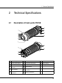
Description of main parts: ES748
13
11
1
12
2
3
4
14
5
6
10
9
15
7
8
1
Front flange
7
Sensors
13
Cylinder
2
8 fixing holes Ø12,5
8
Pneumatic connectors
14
Spiral casing
3
Nose
9
EC plate
15
Fixing surface
4
Pressurisation
labyrinth
10
Serial number
5
ISO coupling
11
Passage of power cables with
connector
6
2 holes M12 for
extraction
12
Sensor connectors
HSD S.p.A. © - 0102h00a.fm051112
13
2 Technical Specifications
2.2
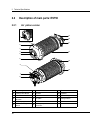
Description of main parts: ES750
2.2.1
Air piston version
13
5*
12
1
11
2
3
14
4
5
6
10
9
15
7
8
1
Front flange
6
2 holes M12 for extraction
12
Sensor connectors
2
8 fixing holes Ø12,5
7
Sensors
13
Cylinder
3
Nose
8
Pneumatic connectors
14
Spiral casing
4
Pressurisation
labyrinth
9
EC plate
15
Fixing surface
5
ISO coupling
10
Serial number
5*
HSK connecting
device
11
Passage of power cables with
connector
14
HSD S.p.A. © - 0102h00a.fm051112
2 Technical Specifications
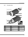
2.2.2
Oil piston version
12
6
9
1
2
3
14
4
5
10
15
12
7
8
7*
16
11
13
1
Front flange
7
Sensors
12
Sensor connectors
2
8 fixing holes Ø12,5
7*
Analogue sensor
13
Cylinder
3
Nose
8
Hydraulic connections
14
Spiral casing
4
Pressurisation
labyrinth
9
EC plate
15
Fixing surface
5
ISO coupling
10
Serial number
16
Fluids distributor
6
2 holes M12 for
extraction
11
Passage of power cables with
connector
HSD S.p.A. © - 0102h00a.fm051112
15
2 Technical Specifications
2.3
Characteristics and performance
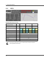
2.3.1
ES748
FNZ4100487 Rev.00 (SP 150.110.62)
Nominal voltage
(supplied by inverter)
V
380
380
380
380
Rated frequency
Hz
133
267
533
800
Rated speed
rpm
2000
4000
8000
12000
Duty type
S1
cont
S6
40%
S1
cont
S6
40%
S1
cont
S6
40%
S1
cont
S6
40%
Rated power
kW
20
24
17
20
12
14
8
8
Rated torque
Nm
95.4
114.5
40.5
47.7
14.3
16.7
6.4
6.4
Rated current
A
45
54
30
40
25
32
20
20
Rated efficiency
0.8
Power factor cos
0.8
Number of poles
8
Insulation class
F
Class IP
54
Cooling type
Weight
Liquid cooling
kg
~ 105
The maximum rated current "S1/cont" is used to set the "maximum continuous
current" parameter of the inverter.
16
HSD S.p.A. © - 0102h00a.fm051112
2 Technical Specifications
Parameters of the equivalent electrical network
unit of
measurement
Value
Nominal power (S1)
kW
20
Nominal current (S1)
A
45
Nominal line voltage
V
380
Nominal speed at nominal load
rpm
1995
Rated frequency
Hz
133
No-load line voltage
V
366
No-load current
A
26.3
Stator resistance (20°C)
0.206
Stator dispersion reactance
Stator dispersion inductance
mH
0.82
Rotor dispersion reactance
0.32
Rotor dispersion inductance
mH
0.38
Main field reactance
0.901
Main field inductance
mH
1.08
Field weakening start speed
rpm
2000
Maximum motor speed
rpm
12000
Description
Rotor resistance (20°C)
0.138
0.682
Power factor
0.80
Rotor moment of inertia
Kg m
Connection
Y or D
HSD S.p.A. © - 0102h00a.fm051112
2
6.57E-02
Y
17
2 Technical Specifications
2.3.2
ES750
FNZ4100497 Rev.00 (SP 150.110.62)
Nominal voltage
(supplied by inverter)
V
380
380
380
Rated frequency
Hz
85
200
667
Rated speed
rpm
1275
3000
10000
Duty type
S1
cont
S6
40%
S1
cont
S6
40%
S1
cont
S6
40%
Rated power
kW
30
36
30
36
11
11
Rated torque
Nm
224
269
95.5
114.6
10.5
10.5
Rated current
A
74
89
70
84
23
23
Rated efficiency
0.8
Power factor cos
0.8
Number of poles
8
Insulation class
F
Class IP
54
Cooling type
Weight
Liquid cooling
kg
~ 150
The maximum rated current "S1/cont" is used to set the "maximum continuous
current" parameter of the inverter.
18
HSD S.p.A. © - 0102h00a.fm051112
2 Technical Specifications
Parameters of the equivalent electrical network
unit of
measurement
Value
Nominal power (S1)
kW
30
Nominal current (S1)
A
74
Nominal line voltage
V
380
Nominal speed at nominal load
rpm
1211
Rated frequency
Hz
85
No-load line voltage
V
373
No-load current
A
61
Stator resistance (20°C)
0.218
Stator dispersion reactance
Stator dispersion inductance
mH
1.1
Rotor dispersion reactance
0.217
Rotor dispersion inductance
mH
0.41
Main field reactance
3.063
Main field inductance
mH
5.7
Field weakening start speed
rpm
1275
Maximum motor speed
rpm
10000
Description
Rotor resistance (20°C)
0.19
0.572
Power factor
0.8
Rotor moment of inertia
Kg m
Connection
Y or D
HSD S.p.A. © - 0102h00a.fm051112
2
1.32E-01
Y
19
2 Technical Specifications
20
HSD S.p.A. © - 0102h00a.fm051112
3 Transport, packing, unpacking, storage
3
Transport, packing, unpacking,
storage
3.1
Warnings
Product lifting and handling operations can create hazardous situations for the personnel
involved. Therefore, it is advisable to follow the instructions supplied by the manufacturer and
to use the appropriate equipment.
The installation and assembly operations must always be carried out by specialised
technicians only.
All the lifting and handling operations of the product and its parts must be performed with
extreme care, avoiding impacts that could compromise its operation or damage any coated
parts.
The user is responsible for selecting the lifting equipment (cables, straps or
chains, etc.) regarded as most suitable in terms of operation and capacity with
respect to the weight of the load indicated on the packing and on the product
label.
3.2
Dimensions and weights
Weight of the packed product: this is reported on the packing.
Linear dimensions of the packed product: these are reported in the documents accompanying
the product.
3.3
Transport and packing conditions
The product is shipped protected by a VCI plastic wrapping and expanded foam, and packed in a
wooden case or in a special cardboard box.
The following figure illustrates methods that can be used to lift the case using cables and a forklift.
In the case of a forklift, make sure that the centre of gravity of the case is between the forks when
lifting.
HSD S.p.A. © - 0103h00a.fm051112
21
3 Transport, packing, unpacking, storage
The examples shown are for information purposes only, in that it is not possible for the
manufacturer to determine all the possible configurations for lifting its products beforehand.
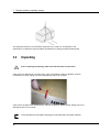
3.4
Unpacking
Prior to opening the packing, make sure that the seals are still intact.
If the product is delivered in a wooden case, insert a screwdriver under the fastener. Use the
screwdriver as a lever, taking care not to damage the case or its contents.
If the product is packed in a cardboard box, remove the strips of adhesive tape, taking care not to
damage the box or its contents.
The expanded foam and plastic wrapping must be disposed of as plastic material.
22
HSD S.p.A. © - 0103h00a.fm051112
3 Transport, packing, unpacking, storage
3.5
Storage
If the product is to be placed in storage, it must be protected against weather, humidity, dust and
aggressive atmospheric and environmental agents.
It is therefore necessary to:
carry out periodic checks to ascertain the general storage condition of the product
Manually rotate the shaft approximately once a month to make sure that the bearings remain
perfectly greased.
STORAGE TEMPERATURE: from +5°C (+41°F) to +55°C (+131°F)
RELATIVE HUMIDITY WITHOUT CONDENSATION: from 5% to 55%
HSD S.p.A. © - 0103h00a.fm051112
23
3 Transport, packing, unpacking, storage
24
HSD S.p.A. © - 0103h00a.fm051112
4 Installation and commissioning
4
Installation and commissioning
4.1
Preliminary installation checks
Before carrying out any operations, MAKE SURE:
that no part of the electrospindle has been damaged by impact or any other cause during
transport and/or handling;
that the connectors are undamaged.
4.2
Preparing the factory services
It is the responsibility of the customer to ensure the availability of the factory services (e.g.
electricity supply, compressed air supply, etc.).
The electricity supply line of the electrospindle must have a sufficient power rating. The connection
to the mains electricity supply must be carried out by a qualified electrician.
The customer is responsible for the entire power supply system to the product
as far as the connectors.
The user must guarantee all the safety conditions necessary for "earthing" the
electrospindle.
The earthing system must comply with current standards in the country of
installation and must be checked regularly by qualified personnel.
HSD S.p.A. © - 0104h00a.fm051112
25
4 Installation and commissioning
4.3
Mechanical connections
The load-bearing structure on which the product is to be mounted must be sufficiently rigid to
support the weight and type of machining to be carried out.
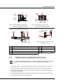
4.3.1
Fixing structure for spindles with round casing
The fixing structure to which the spindle is fixed,
must have a flatness of less than 0.015 mm and a
perpendicularity to the axis of the spindle of less
than 0.015 mm.
r 0,015
n A 0,015
1
Fixing structure
of the electrospindle
2
Electrospindle
-An A 0,015
1
r 0,015
2
26
HSD S.p.A. © - 0104h00a.fm051112
4 Installation and commissioning
4.3.2
Tool change system
The tool holder magazine has to position the cones with the following accuracy:
both ISO and HSK: concentricity between the spindle shaft and tool holder cone
0,2 mm;
HSK only: perpendicolarity between the spindle shaft and the tool holder contact
surface 0,1 mm.
ISO
HSK
-B-
-A1
-Ca C 0,2
a A 0,2
3
n B 0,1
1
Spindle shaft ISO
2
Tool holder cone ISO
3
HSK spindle shaft
4
HSK tool holder cone
4
2
4.4
Specifications for the compressed air supplied to
the manufacturer's products
Introduce compressed air with purity according to ISO 8573-1, Class 2 4 3, i.e.:
• Class 2 for the solid particles: size of the solid particles < 1 m;
• Class 4 for humidity: dew point < 3°C (37.4°F);
• Class 3 for total oil: oil concentration < 1 mg / m3;
Failure to comply with these specifications may cause the malfunction of the
electrospindle.
The guarantee will be deemed as null and void if traces of pollutants are found
during repairs.
HSD S.p.A. © - 0104h00a.fm051112
27
4 Installation and commissioning
For example, compliance with the above specifications can be obtained following the
instructions written below:
If the machine has a lubricated air circuit, this must be isolated from the dry air circuit
feeding the electrospindle by means of non-return valves.
The filters shown in diagrams of the following figures must be installed as close as
possible to the electrospindle.
In view of the fact that the efficiency of the filters is <100%, it is important that the
machine tool is supplied with suitably treated air.
As an indication, introduce compressed air with a purity according to ISO 8573-1,
classes 7 6 4, into the circuits illustrated below, i.e.:
• Class 7 for solid particles:
dimensions of solid particles < 40 µm;
concentration of solid particles < 10mg/m3.
• Class 6 for humidity:
dew point < 10°C (°F).
• Class 4 for total oil:
oil concentration < 5 mg / m3.
At the end of the working day, discharge the compressed air system to allow the
filters to drain automatically.
Perform regular maintenance on the filters in line with the manufacturer's
instructions and replace them when they become saturated and less efficient
(approximately every 6/12 months).
1
4
2
28
3
1.
Main compressed air supply.
2.
Pre-filter 5 µm.
3.
Oil separator filter 0.1 µm.
4.
To the manufacturer's product.
HSD S.p.A. © - 0104h00a.fm051112
4 Installation and commissioning
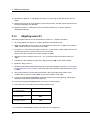
4.5
Example diagrams for pneumatic circuits by the
customer
4.5.1
Actuation of the tool change piston (air actuation)
Optional
7
2
5
10
9
6
11
1
4
3
8
1
6 bar mains supply pressure
7 monostable 5-2 valve with electro-pneumatic
control and spring return
2
air multiplier 2:1
8 unidirectional flow regulator
(to adjust the locking impulse)
3
pre-filter 5 µm
9 cylinder for the tool change
4
oil separator filter 0.1 µm
10 Tool release air inlet
5
pressure regulator: min 6 bar
max 10 bar
11 Piston at the upper end of stroke return air
inlet
6
pneumatic tank *
*
Tank volume = 0,4 l (useful volume 0,28 l)
The cylinder of this electrospindle is double acting: the cylinder must be kept under
pressure when the piston needs to be kept at the upper end of stroke with the tool
locked, away from rotating parts.
HSD S.p.A. © - 0104h00a.fm051112
29
4 Installation and commissioning
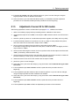
4.5.2
Actuation of the tool change piston (oil actuation optional)
The circuit indicated here is merely an example
The electrospindle ES750 may be optionally fitted with an oil-type cylinder to perform the tool
change operations.
An example system layout is shown below.
1
2
6050bar
bar
5
6
30 bar
3
4
1 High pressure circuit (60 bar)
4 Safety switch on the piston recovery circuit
(calibrated at 30 bar)
2 Low pressure circuit
5 Oil inlet for tool release
3 Bistable solenoid valve
6 Oil inlet for tool locking
It is not necessary to supply 60 bar constantly for tool locking.
When the safety switch has confirmed piston recovery at the upper limit switch, you can
reduce the pressure to 10 bar.
30
HSD S.p.A. © - 0104h00a.fm051112
4 Installation and commissioning
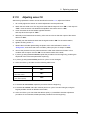
4.5.3
Pressurization supply
4 Bar
4
6
1
(D)
3
2
5
1
6 bar mains supply pressure
4
pressure regulator 4 bar
2
pre-filter 5 µm
5
pressure switch calibrated to 4 bar
3
oil separator filter 0.1 µm
6
electrospindle pressurisation
The circuits proposed are indicative only.
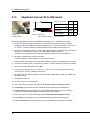
4.6
ES748 and ES750 connections for air cylinder
2
5
3 1 4
Compressed air connection points
*
1
Tool locking air inlet (piston return)
5 barmin - Ø8
2
Cleaning of cone 4 bar / tool coolant*
Ø 10
3
Tool change air (expulsion)
6,5 barmin - Ø8
4
Electrospindle pressurisation air inlet
4 bar - Ø8
5
DPC Pressurisation air inlet
4 bar - Ø8
Max. pressure 4 bar
HSD S.p.A. © - 0104h00a.fm051112
31
4 Installation and commissioning
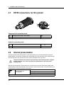
4.7
ES750 connections for Oil cylinder
3
1
4
2
Compressed air connection points
1
Cleaning of cone 4 bar / tool coolant*
Ø6
2
Electrospindle pressurisation air inlet
4 bar - Ø8
* Max.
pressure 4 bar
Hydraulic connection points
3
Oil inlet for tool release
60 barmin - G1/4
4
Oil inlet for tool locking
10 barmin - G1/4
4.8
Internal pressurisation
The internal pneumatic pressurisation circuit prevents the entry of harmful particles inside the
electrospindle. This must be supplied with compressed air at 4 bar (58 PSI), which outlets through
the front labyrinth in the spindle nose area, and the drainage holes of the DPC.
The pressurisation air must also be present when the electrospindle is stopped
and the machine is on. This will prevent the penetration of dust from other
working areas.
With the spindle stopped, check that there is a uniform flow of air from around the spindle shaft
(pressurisation) and in the drainage holes of the DPC. If this is not the case, check the efficiency of
the pneumatic circuit and check the connections.
Pressurisation air
consumption
4800 litres/hour(*)
80 l/min.(*) ± 10%
2.8 cfm(*)
(*) volume with: P = 4 bar (58 PSI) and T = 20°C (68° F)
32
HSD S.p.A. © - 0104h00a.fm051112
4 Installation and commissioning
4.9
Refrigerator
The manufacturer recommends the use of demineralized water for the cooling system with the
addition of 10% ethylene glycol and anti-corrosion additives to ensure the smooth operation of the
circuit and the motor.
The gaskets isolating the cooling circuits inside the electrospindle are made of
NBR: use additives that do not degrade this material.
On request, the manufacturer supplies ARTIC-FLU-5 (code: H2161H0022) which is a pre-mixed
ready-to-use liquid coolant tried and tested by himself.
The product contains monoethylene glycol and eco friendly corrosion inhibitors, without amines,
nitrates and phosphates, and can guarantee protection against corrosion for approximately 1 year.
ARTIC-FLU-5 prevents the formation of rust, scale and foam deposits as well as hardening,
cracking and swelling of seals and couplings.
The coolant complies with various international standards, including CUNA NC 956-16.
4.9.1
Cooler specifications
3400 W (ES748)
Cooling capacity
5200 W (ES750)
Minimum flow
5 litres/minute
Coolant type
Demineralized water
+ 10% Ethylene Glycol + corrosion inhibitor
Cooler set temperature
+25+/-3°C (+77+/-5°F)
4.9.2
Cooling characteristics
Input cooling temperature: t = 20 °C - 30 °C
Anticorrosive means: Vmax = 25 Vol%
Solid materials filter < 100 µm
Type of water additives
BRAND
TIPO (TYPE)
ARAL
SAROL 340 - 2 ÷ 3 %
CINCINNATI
CINCINNATI CIMCOOL MG 602 - 4 %
HENKEL
P3 - PREVOX 6710 - 2 ÷ 3 %
CASTROL
SYNTILO R PLUS - 2 ÷ 3 %
HSD S.p.A. © - 0104h00a.fm051112
33
4 Installation and commissioning
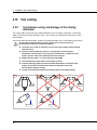
4.10 Tool cooling
4.10.1
Tool internal cooling and drainage of the rotating
distributor
The cooling water runs through the rotating distributor to the tool (DPC, patented). The excess
water runs through the DPC drainage holes. The more the tool obstructs the flow the more the
drained water.
The excess water gets eliminated. To allow a complete drainage, refer to the following instructions:
To make the distributor (DPC) correctly works and to avoid ruining the
electrospindle, follow the instructions below:
The water to be used to internally cool the tool must comply with the below
characteristics;
Filter the cooling water by means of a 25 µm filter. Perform regular
maintenance on the filter in line with the manufacturer's instructions and
replace it when it becomes saturated and less efficient;
Supply the DPC with a < 10 l/min delivery (0,35 CFM);
The distributor drainage holes must always be clear;
The DPC drainage pipes must be orientated downwards. The pipes must
remain downwards orientated even when the machine moves the
electrospindle (figures below);
Tilt the electrospindle towards the drainage holes side (figure below).
DPC
!
34
HSD S.p.A. © - 0104h00a.fm051112
4 Installation and commissioning
4.10.2
Tool external cooling
The water to be used to externally cool the tool must comply with the below characteristics:
aggressive index (A.I.) = 11-12
Electric conductibility no greater than 600 microS/cm
Turbidity not higher than 20 mg/l
Chlorides no greater than 300mg/l
Only with an accurate analysis is it possible to establish whether the water used for
the machining operation falls within the required parameters.
Do not use additives with sodium chloride (NaCl) as they provoke corrosion
(rust).
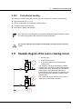
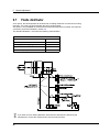
4.11 Example diagram of the cone's cleaning circuit
1
2
(T)
HSD S.p.A. © - 0104h00a.fm051112
1
Air inlet 4 bar
2
Water inlet for the tool
3
To be connected to the tool coolant/cone
cleaning inlet
The diagram in the figure represents a possible
example of the pneumatic circuit for the automatic
cleaning of the cone. During the tool change the
water supply is interrupted and replaced by
pressurised air, which removes any particles. The
jet of compressed air must be on until the collet
remains open.
The control and regular cleaning of the cone is
imperative, as described in chapter 7.
3
35
4 Installation and commissioning
4.12 Electrical connections
The electricity supply to the electrospindle MUST be through an inverter.
The position of the electrical connectors or the outlet of the free cables is shown in
paragraph 2.1.
In addition to the supplied electrical plug connector, pre-wired plug connectors of various
lengths are also available on request.
4.12.1
Power cables
WHITE
U Phase
RED
V Phase
BLACK
W Phase
YELLOW/GREEN
Earth
36
HSD S.p.A. © - 0104h00a.fm051112
4 Installation and commissioning
4.12.2
Encoder wiring + motor thermal probe
ES748
Encoder L+B 1Vpp and TTL
with connector
UB+
(ROSA)
UB(NERO)
UA+
(BIANCO)
UB = 5V
(ROSSO)
UA(MARRONE)
5V SENSE
(VERDE)
UN(GIALLO)
SCHERMO
UN+
(GRIGIO)
0V GND
SONDA TERMICA MOTORE
SONDA TERMICA MOTORE
0V GND
(BLU)
TTL manufacturer encoder
without connector
Yellow
A+
GREEN
A-
BROWN
B+
BLUE
B-
GREY
N+
WHITE
N-
RED
24V
BLACK
0V
BROWN
THERMAL
BROWN
THERMAL
PONTE PIN 15 CON PIN 7
ES750
Encoder L+B 1Vpp and TTL
without connector
TTL manufacturer encoder
without connector
WHITE
UA+
Yellow
A+
BROWN
UA-
GREEN
A-
PINK
UB+
BROWN
B+
BLACK
UB-
BLUE
B-
GREY
UN+
GREY
N+
Yellow
UN-
WHITE
N-
RED
UB = 5V
RED
24V
BLUE
0V GND
BLACK
0V
GREEN
5V Sense
BROWN
THERMAL
BROWN
THERMAL
HSD S.p.A. © - 0104h00a.fm051112
37
4 Installation and commissioning
4.12.3
Sensor connections
Sensor unit ES748 and ES750 with air cylinder
4
1 +Vcc
3 0V
4 Output
1
3
100
Sensor unit ES750 with oil cylinder
4
1 +Vcc
3 0V
4 Output
4.12.4
1
3
Analogue sensor
Available as an option only with electrospindles ES750 with oil cylinder.
COLOUR
Signal
BROWN
24V
BLUE
0V
BLACK
Output
38
HSD S.p.A. © - 0104h00a.fm051112
5 General post-installation checks
5
General post-installation checks
5.1
Electrospindle pre-startup checks
5.1.1
Pneumatic circuit
The tubes of the pneumatic circuit must be of the diameter specified in section 4.6 “ES748 and
ES750 connections for air cylinder”. Introduce dried and filtered compressed air according to
the specifications in the said section;
for the connections, see possible labels on the product, and section 4.6 “ES748 and ES750
connections for air cylinder”;
the pressurising air must always be present, even when the electrospindle is stationary: check
(with the electrospindle stationary and the tool holder inserted) that a uniform and continuous
flow of air exits from the labyrinth on the spindle nose;
the cone cleaning air must be present during the tool change;
The progress of the tool holder cone ejection must be that specified in section 6.4.1 “Tool
holder locking and ejection device”.
5.1.2
Hydraulic circuit
The liquids used must meet the specifications and instructions in section 4.9 “Refrigerator”.
5.1.3
Electrical circuit
The earth of the product (indicated in the section from 4.12) must be
connected to the earth of the machine;
The thermal cut-out must activate a safety procedure to protect the
electrospindle windings against overheating (see section 6.9.5 “Use and
technical characteristics of the thermal alarm”).
HSD S.p.A. © - 0105h00a.fm051112
39
5 General post-installation checks
5.1.4
Inverter programming
The maximum voltage set on the inverter must correspond to the rated value indicated on the
motor rating plate.
The set frequency value at which the voltage becomes maximum (rated frequency) must
correspond to the rated value indicated on the motor rating plate.
The maximum speed set on the inverter must correspond to the value indicated on the motor
rating plate.
The maximum continuous current set on the inverter must correspond to the rated current
value indicated on the motor rating plate.
Contact the manufacturer if it is considered necessary to check the other parameters of the
inverter.
40
HSD S.p.A. © - 0105h00a.fm051112
5 General post-installation checks
5.2
First start-up checks
Start the electrospindle only if the sensors (where present) verify the following
conditions simultaneously:
Sensor 1
ON
Tool holder cone present
Sensor 2
OFF
Collet closed
Sensor S1+S4
(HSK versions only)
ON
Tool holder cone inserted and in contact with the
HSK surface
Sensor 5
ON
Piston in safety
The sensor “ON” condition corresponds to an output of +24 V.
The sensor “OFF” condition corresponds to an output of 0 V.
With ES750 fitted with oil cylinder, only start up the electrospindle if the
sensors indicate that the tool is connected - see the table in paragraph 6.9
“Sensors”.
The electrospindle must not be started without the tool holder inserted.
The cylinder of the spindle is double acting: the cylinder must be kept under
pressure to hold the piston on the upper limit switch, away from fast-rotating
parts.
The safety condition is indicated by the output “ON” of sensor S5.
The control sensors must intervene according to the logic described in paragraph
6.9 “Sensors”.
The tool change cycle must only take place with the shaft stopped.
with the tool holder inserted and without performing machining operations, perform the
preheating cycle described in paragraph 6.3.
HSD S.p.A. © - 0105h00a.fm051112
41
5 General post-installation checks
42
HSD S.p.A. © - 0105h00a.fm051112
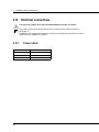
6 Use and adjustment
6
Use and adjustment
6.1
Environmental conditions
The manufacturer has tested and verified its electrospindles according to environmental conditions
standard (IEC 60034-1:2006-05).
Contact the manufacturer for information regarding applications in special environments.
6.2
Running-in
Prior to being packed, the electrospindle is subjected to an automatic running-in cycle to ensure
the correct distribution of lubricant (long-life grease) along the ball races of the bearings and to
run-in the balls and races of the bearings themselves. The running-in cycle also includes a
detailed check of all the control and signalling devices through the simulation of various machining
cycles on the test-bench.
6.3
Warm-up
The manufacturer uses high-precision angular contact bearing pairs, pre-loaded and lubricated for
life with special high-speed grease.
When starting-up the electrospindle for the first time each day, allow it to run a short warm-up cycle
to allow the bearings to gradually reach a uniform operating temperature and obtain uniform
expansion of the races and correct pre-loading and rigidity.
The following cycle, with a tool holder inserted and without performing
machining operations, is recommend:
50% maximum rated speed for 2 minutes;
75% maximum rated speed for 2 minutes;
100% maximum rated speed for 1 minute.
Pre-heating cycle must also be performed each time the machine is not
working for a period of time sufficient to cool the electrospindle to room
temperature.
During machining, the spindle can reach high temperatures and, as such, must
not be touched without taking the due precautions.
To perform the preheat it is necessary to insert a tool-holder WITHOUT a tool.
HSD S.p.A. © - 0106h00a.fm051112
43
6 Use and adjustment
6.4
6.4.1
Collet
Tool holder locking and ejection device
The tool holder is locked mechanically by means of elastic springs that develop an axial force
equal to:
ELECTROSPINDLE MODEL
AXIAL FORCE OF THE
SPRING
AXIAL FORCE ON THE
TOOL HOLDER
ISO 50
9900 N +/- 10%
9900 N +/- 10%
HSK B100
9800 N +/- 10%
28000 N +/- 10%
The tool holder locking and ejection are activated by the movement of a double-acting compressed
air piston with a pressure of 10.
6.5
Tool holder cone
The geometry of the taper of the cones must comply with norm DIN69893;
The geometry of the taper of the cones has to reflect the standard DIN69871;
Avoid the presence of inserts, slots or other forms that could disturb the dynamic balance of
the tool holder;
The dynamic balance quality grade must be G = 2.5 or better (standard ISO1940);
The balancing is carried out with the tool holder assembled (cone, spring collet, ring nut, tool).
It is forbidden to use tool holders that do not comply with the above conditions.
Non compliance with these instructions can lead to a risk of breakage or an
imperfect coupling of the tool holder cone, with the resulting risks for the user.
NOTE:
L1
44
L2
In the ISO tool-holders, the
tenons positions does not
comply with norm DIN69871.
For further information refer
to the spindle drawing.
L1 = L2
HSD S.p.A. © - 0106h00a.fm051112
6 Use and adjustment
6.5.1
General recommendations regarding tool holder cones
IMPORTANT:
The choice of tool holder is a determining factor as regards safety.
The tapered surfaces of the tool holder and its housing on the spindle-shaft must be
kept extremely clean to allow safe coupling (see section 7 “Programmed
maintenance”).
During machining operations, avoid all contact whatsoever between the non-cutting
rotating parts and the piece being machined.
The tool holder cone seating must always be protected against the entry of impurities:
use a suitable plug or a tool holder cone.
At the end of the working day, always remove the tool holder cone from the
electrospindle to avoid sticking. Close the tool holder housing using a clean tool holder
cone at ambient temperature.
Do not rotate the electrospindle without a tool holder inserted. Rotating the electrospindle
without a tool holder will upset the balance and operation of the HSK collet. The tool
holder must be introduced until in contact with the nucleus of the collet.
6.6
Tool
The tools must have a dynamic balance grade of G=2.5 or greater (standard ISO1940).
RESPECT THE MAXIMUM REVOLUTIONS PER MINUTE (rpm) INDICATED BY
THE TOOL MANUFACTURER.
Depending on the type and quality of the machining operation to be performed, and the material
used, it is the users responsibility to operate at lower speeds (NEVER HIGHER) than those
specified by the tool manufacturer.
When selecting the tool to use, the following recommendations must be taken into consideration:
Always use tools with optimum sharpness qualities and correctly tightened in the relative tool
holder.
Never use deformed or damaged tools or those with missing parts or not perfectly balanced.
Always make sure that all the surfaces are unmarked and perfectly clean before inserting the
tool in the relative collet.
The essential requisites for using high-speed tools are:
- compact, short and light tools
- precise, with any inserts correctly fitted with a high degree of safety
- balanced and symmetrically coupled with the tool holder
- with cutting edges near to the rotation axis.
HSD S.p.A. © - 0106h00a.fm051112
45
6 Use and adjustment
6.7
Fluids distributor
As an option, the electrospindle can be fitted with a rotating distributor for internal tool cooling
purposes. The cooling is performed with the aid of cooling liquids.
This option is only available for the ES750 electrospindle, fitted with oil cylinder.The hydraulic
connection points are illustrated in section 4.9.
The standard distributor must have the following characteristics:
Characteristics
Minimum pressure
5 bar
Maximum pressure
80 bar
Cooling liquid filtering degree
50 µm
Dry rotation*
possible
Maximum capacity
60l/min
*
not allowed with pressurised air
If you want to use a rotating distributor other than the standard one offered by the
manufacturer, contact the manufacturer's technical service office.
46
HSD S.p.A. © - 0106h00a.fm051112
6 Use and adjustment
6.8
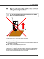
Procedure to follow if the tool becomes jammed
in the piece being machined
For models with ISOP type tool coupling, in the case where the machine goes
into alarm status or stops with the tool locked onto the piece being machined,
do not move the spindle along the Z-axis!
Z
Y
X
If possible, free the piece by hand and then perform a tool change.
If this is not possible, proceed as follows:
Supply air to the tool change circuit;
Slowly move the spindle away from the work piece by moving it along the Z-axis until the collet
opens (sensor S2 output “ON”);
Make sure that the cone has been freed from the collet;
Move the spindle away from the work piece;
Then manually remove the jammed tool.
If this procedure is not followed, the tool holder will drag the locking system (collet/screw dowel)
with it until the cone is released. After which, the collet will move back violently due to the force
exerted by the spring and could cause damage to the screw dowel.
HSD S.p.A. © - 0106h00a.fm051112
47
6 Use and adjustment
1
2
3
4
UTENSILE BLOCCATO
UTENSILE RILASCIATO
IMPATTO
5
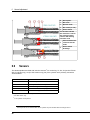
6.9
N.
Description
1
ISO cone
2
Spindle shaft
3
ISO collet (or nut)
4
Screw dowel
The arrows indicate
the direction in which
the locking system
returns after having
freed the cone
5
Point at which the
collet will hit the
shaft
6
Screw dowel
breakage
6
Sensors
The electrospindles are fitted with inductive sensors1 for monitoring, S1, S2, S3 (version ES750
with oil cylinder only), S4 (for HSK version only), S5 (if the cylinder unit is present), and with a
"thermal alarm".
NAME
SIGNAL INFORMATION
S1
Tool holder present
S2
Collet open - Tool uncoupled
S3*
Tool is lacking or is too long
S1+S4**
Correct tool holder coupling
Piston at the upper end of stroke
S5***
*
Only for ES750 version with oil cylinder
**
For HSK version only
***
If the cylinder unit is present
1 Electrospindle
48
version ES750 fitted with oil cylinder may also be fitted with an analogic sensor.
HSD S.p.A. © - 0106h00a.fm051112
6 Use and adjustment
6.9.1
Electrospindle statuses and corresponding analogue
sensor outputs
Reading range
2÷5
Power supply
14 ÷ 30
V DC
Output voltage
0 ÷ 10
V
Collet closed without tool
3,5 ÷ 5
V (23°)
Collet closed, tool coupled
2 ÷ 3,5
V (23°)
Tool badly coupled
1,2 ÷ 2
V (23°)
0,8 ÷ 1,2
V (23°)
Output voltage
Tool ejected
6.9.2
mm
Technical characteristics of inductive sensors
Proximity PNP type Normally Open (N.O.)
Power supply voltage
10 - 30V (DC)
Maximum load
100 mA
No-load absorption
<17 mA
Nominal reading distance
1 mm
S4 (HSK version)
Proximity PNP type Normally Closed (N.C.)
Power supply voltage
10 - 30V (DC)
Maximum load
100 mA
No-load absorption
<17 mA
Nominal reading distance
1 mm
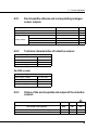
6.9.3
Status of the electrospindle and output of the inductive
sensors
S1
S2
S5
Collet open
(tool holder cone ejected)
OFF
ON
OFF
Tool holder cone locked correctly
ON
OFF
ON
Collet closed but with no tool holder cone
OFF
OFF
ON
* according to the operational status of the machine
HSD S.p.A. © - 0106h00a.fm051112
49
6 Use and adjustment
HSK B100
S1
S2
S1+S4
S5
Collet open
(tool holder cone ejected)
OFF
ON
OFF
OFF
Tool holder cone locked correctly
ON
OFF
ON
ON
Collet closed but with no tool holder cone
OFF
OFF
OFF
ON
* according to the operational status of the machine
ES750 with oil cylinder
Status
S1
S2
S3
Tool released
OFF
ON
OFF
No tool holder
ON
OFF
ON
Tool holder connected
ON
OFF
OFF
Tool holder badly connected (case 1: tool
too
long)
ON
OFF
ON
Tool holder badly connected (case 2: tool
too
short)
OFF
OFF
OFF
Tool holder present but not correctly locked. This situation is indicated by the output:
S1
S1+S4
ON
OFF
This condition is dangerous: if it is detected, stop the rotation or the tool change procedure, inspect
the machine and remove the cause preventing the tool holder from coupling correctly.
The electrospindle shaft can only rotate in the "tool holder cone correctly
locked" state. If outputs S1+S4 and S5 change to “OFF”, stop the rotation of the
electrospindle shaft.
50
HSD S.p.A. © - 0106h00a.fm051112
6 Use and adjustment
6.9.4
Description of the sensors
Sensor S1: “Tool holder present” signal
The signal from sensor S1 indicates the presence of the tool holder cone.
Ignore output S1 during the period from the release command to the couple tool
command.
Sensors S1+S4: Tool holder locked signal
Both sensors S1 and S4 are connected in series:sensor S1 checks the presence of the tool holder
cone, and in case it is present it enables the reading of sensor S4 which will check its position. The
output only changes to “ON” if both conditions are verified as positive.
Ignore the S1+S4 output during the period from the release command to the couple
tool command.
Sensor S2: “collet open” signal
Signal S2 is used during the tool change cycle: it detects the opening of the collet and
whether it is possible to continue with the next phases of the tool-change cycle.
Sensor S5: Piston “upper end of stroke” signal
Sensor S5 is “ON” when the piston is at the upper end of stroke position.
The piston is double acting and should therefore be fed to be moved and maintained in this
position. The electrospindle can be seriously damaged if the rotation occurs when the piston is not
at the upper end of stroke position.
The electrospindle shaft can only rotate in the "tool holder cone correctly
locked" state. If outputs S1 or S5 change to “OFF”, stop the rotation of the
electrospindle shaft.
The ES750 electrospindle with oil cylinder is fitted with sensor S3 instead of sensor S5.If sensor
S3 is ON then the tool is lacking or is too long.
Sensor S3: Lacking tool or too long tool signal
The signal from sensor S3 indicates the lacking of the tool in the closed collet or indicates a too
long tool in the cone (out of tolerance).If the shaft starts running this will ruin the collet and could
break and release some parts of the electrospindle.
HSD S.p.A. © - 0106h00a.fm051112
51
6 Use and adjustment
6.9.5
Use and technical characteristics of the thermal alarm
The electrospindle is fitted with a normally-closed bimetallic strip switch inserted in the electric
windings of the stator which opens when a temperature that may damage the windings is reached.
The contacts re-close when the temperature reduces and returns to the safe values.
The thermal alarm must be connected to the Numerical Control, which should interrupt the
machining operation and stop the rotation of the spindle shaft if the switch opens.
If the shaft stops while the tool is still being pushed against the piece being
machined, the spindle bearings may break. If the tool is not immediately moved
away from the piece and the rotation stopped, there is a risk of burning out the
stator.
For the bimetallic strip switch connection, see section 4.12 “Electrical connections”.
Technical characteristics of the bimetallic strip:
Power supply
48 V DC MAX
Current
1.6 A MAX
Switching cycles
10000 Cycles
Contact interruption time
< 1 ms
Contact resistance (according to MIL R 5757)
< 50 m
Isolation voltage
2 kV
6.10 Encoder
6.10.1
General description
The encoder incrementally encodes the position data detected by signals A and B, A negated and
B negated.
The signals are in phase quadrature, i.e. the signals A, B, A- ??and B- are offset from each other
by 90 degrees.
The encoder also provides Zero and Zero denied signals.
There are two encoder models available with a different number of rotation pulses depending on
the electrospindle:
"Square Wave" from the manufacturer;
Lenord+Bauer "Square Wave";
"Sine" (Lenord+Bauer);
52
HSD S.p.A. © - 0106h00a.fm051112
6 Use and adjustment
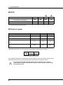
6.10.2
Technical characteristics of the manufacturer's
rectangular encoder
CHARACTERISTICS
VALUE
Rated power supply
12 V DC ÷ 24 V DC +/- 10%
Absorption
99 mA to 12 V DC
51 mA to 24 V DC
Operating temperature
0°C ÷ 70°C (+32°F ÷ 158°F)
Max. operating altitude
2000m (6500ft)
Signal input
750 pulses per rotation + zero notch
Signal output
TTL electrical levels compatible (0V, +5V line driver)
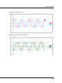
Manufacturer's Square Wave encoder signal
T
D
5V
A
0V
5V
B
0V
5V
A
0V
5V
B
0V
5V
Z
Z
T
Period
D
Phase displacement (D=T/4)
HSD S.p.A. © - 0106h00a.fm051112
0V
5V
0V
53
6 Use and adjustment
6.10.3
Lenord+Bauer Square Wave Encoder technical
specifications
CHARACTERISTICS
VALUE
Rated power supply
5V DC +/- 5%
Operating temperature
-30°C ÷ +85°C (-22°F ÷ +185°F)
Max. operating altitude
2000m (6500ft)
Signal input
1024 pulses per rotation + zero notch
Signal output
TTL electrical levels compatible (0V, +5V line driver)
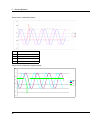
Lenord+Bauer Square Wave Encoder Signals
T
D
5V
A
0V
5V
B
0V
5V
A
0V
5V
B
0V
5V
Z
Z
T
Period
D
Phase displacement (D=T/4)
0V
5V
0V
A voltage level higher than the one specified (5V ±5%) may damage the encoder
reader.
54
HSD S.p.A. © - 0106h00a.fm051112
6 Use and adjustment
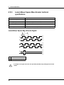
6.10.4
Technical characteristics of the Lenord+Bauer sine
encoder
CHARACTERISTICS
VALUE
Rated power supply "U"
5V DC +/- 5%
Operating temperature
-30° C ÷ 85° C (-22° F ÷ 185° F)
Max. operating altitude
2000m (6500ft)
Signal input
256 pulses per rotation + zero notch
A/B signal output
500 mV peak-to-peak with average value “U ref.”=U/2
1V peak-to-peak as difference of signals with average value
“U ref.” (see figures below)
A/B signal phase displacement
90° (a quarter period)
Z signal output
500 mV peak compared with idle value
U ref. ±80mV
1V peak as difference of signals with idle value
U ref.-160mV= 2.34V (see figures below)
HSD S.p.A. © - 0106h00a.fm051112
55
6 Use and adjustment
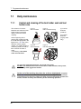
Temporal flow of signal A:
A
3
2,75
2,5
2,25
2
A3
2,75
2,5
2,25
2
A diff= (A) - (A-)
3,25
3
2,75
2,5
2,25
2
1,75
56
HSD S.p.A. © - 0106h00a.fm051112
6 Use and adjustment
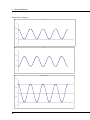
Temporal flow of signal B:
B
3
2,75
2,5
2,25
2
B3
2,75
2,5
2,25
2
B diff= (B) - (B-)
3,25
3
2,75
2,5
2,25
2
1,75
HSD S.p.A. © - 0106h00a.fm051112
57
6 Use and adjustment
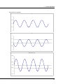
Temporal flow of signal Z:
Z+
3
2,75
2,5
2,25
2
Z3
2,75
2,5
2,25
2
Z diff= (Z) - (Z-)
3,5
3,25
3
2,75
2,5
2,25
2
1,75
58
HSD S.p.A. © - 0106h00a.fm051112
6 Use and adjustment
Displacement of signals A and B
3
2,75
2,5
A
B
2,25
2
Displacement of signals A and B negated
3
2,75
2,5
AB-
2,25
2
HSD S.p.A. © - 0106h00a.fm051112
59
6 Use and adjustment
Temporal flow of differential signals:
T
Period
D
Phase displacement (D=T/4)
A diff.
(A) - (A-)
B diff.
(B) - (B-)
Z diff.
(Z) - (Z-)
Temporal flow of differential negated signals:
3,25
3
2,75
2,5
A diffB diff-
2,25
Z diff-
2
1,75
1,5
60
HSD S.p.A. © - 0106h00a.fm051112
7 Programmed maintenance
7
Programmed maintenance
In order to be able to work in complete safety on an electrospindle installed on a
machine, refer to the machine's instruction manual.
Fully complying with programmed maintenance is essential for maintaining the
usage and operating conditions envisaged by the manufacturer at the moment
the product is placed on the market.
The frequency was assessed considering a 5-day working week, 8 hours per day
under normal working conditions.
Thoroughly read this section before carrying out any maintenance operations on the
electrospindle.
The safety requirements to take into account during the various phases of maintenance work on
the electrospindle are:
the maintenance and/or lubrication operations must only be carried out by qualified skilled
personnel, appropriately authorised by the technical management of the works and in
accordance with current directives and standards, using equipment, tools and products
suitable for the purpose.
Suitable clothing must be worn when carrying out maintenance operations, such as close-
fitting overalls and safety shoes, and avoiding at all costs loose clothing and that with
protruding parts.
During the various maintenance phases, it is advisable to delimit the machine and identify it
with a sign indicating "MACHINE UNDER MAINTENANCE".
During all maintenance operations, make sure that the electrospindle:
is disconnected from the electricity supply
and that the tool is absolutely stationary (not rotating).
The maintenance manager must make use of a well co-ordinated team of personnel capable of
guaranteeing the absolute safety of anyone exposed to possible hazardous situations. All
personnel taking part in the maintenance operations must be in full visual contact with each other
in order to be able to signal any dangers that may arise.
HSD S.p.A. © - 0107h00a.fm051112
61
7 Programmed maintenance
7.1
7.1.1
Daily maintenance
Control and cleaning of the tool holder seat and tool
holder cone
The surfaces of contact
between tool holder and tool
holder seat must be kept
clean to ensure a secure
coupling.
At the beginning of the
working day, make sure that
the surfaces highlighted in the
figures from 1 to 4 are clean,
and free of dust, grease,
coolant, oil, metal particles or
machining waste, as well as
free of traces of oxide or
scale;
if necessary, clean with a
clean and soft cloth.
Figure 1:
ISO tool holder
Figure 2:
ISO tool holder housing
1
1
Figure 3:
HSK tool holder
(1) Conical
surfaces
(in black)
(2) Contact
surfaces
(in grey, HSK
only)
Figure 4:
HSK tool holder seat
1
2
2
1
To clean the highlighted surfaces, use a soft clean cloth;
DO NOT use abrasive tools such as steel wool, metal brushes, emery cloth,
acids or any other aggressive means.
At the end of the working day clean the surfaces highlighted in figures
from 1 to 4 with a soft and clean cloth; imperfect cleaning can lead to serious
consequences for the user's safety, the wear of the electrospindle and the tool
holder, and the accuracy and efficiency of the machining operation.
62
HSD S.p.A. © - 0107h00a.fm051112
7 Programmed maintenance
Never direct a jet of
compressed air in the zone of
the pressurised labyrinth seal,
in that any infiltration would
damage the interior of the
electrospindle.
Do not direct a jet of
compressed air inside the
electrospindle when the tool
holder is not coupled, as this
could dirt the mating surface
with the tool holder or cause
machining residues to enter the
electrospindle itself.
7.1.2
1
Coupling surface
2
Labyrinth seal
1
2
Protection of the tool holder seat
The tool holder seat must always be protected from the intrusion of impurities, which could soil,
oxidise, or in any way degrade the contact surfaces: never leave the electrospindle without a tool
holder cone inserted.
The cone used for protection must not have through holes.
To avoid sticking, remove the tool holder in the electrospindle both after any
heavy work as well as at the end of the working day, and replace it with a clean
tool holder at room temperature to protect the interior of the electrospindle from
the external environment.
The tool holder to be removed may be hot! Use gloves!
HSD S.p.A. © - 0107h00a.fm051112
63
7 Programmed maintenance
7.2
7.2.1
Biweekly maintenance
Tool holder cone cleaning with alcohol
For all versions:
• Carefully clean the contact surfaces of the tool holders (shown in the figure 1 and 3) with a
clean and soft cloth, moistened with ethyl alcohol;
7.3
Bearings
Do not touch the bearings as they are permanently lubricated with special high
speed grease, and DO NOT NEED THE PERIODIC ADDITION OF GREASE.
64
HSD S.p.A. © - 0107h00a.fm051112
8 Replacing components
8
Replacing components
In order to be able to work in complete safety on an electrospindle installed on a
machine, refer to the machine's instruction manual.
The electrospindle contains a spring that has been pre-loaded with a force of
around one hundred kilograms. This spring is applied to a screw dowel that can
be violently ejected if the electrospindle is dismantled by inadequately trained
personnel.
Only carry out the operations described in this manual. Follow the instructions
scrupulously and in the case of doubt, contact the Manufacturer's Assistance
Service.
Observe the maintenance safety instructions given on page 61.
Replacement and adjustment operation are only authorised with the original
spare parts of the manufacturer described in this section of the manual.
Any other type of intervention is not allowed and will invalidate the warranty.
HSD S.p.A. © - 0108h00a.fm051112
65
8 Replacing components
8.1
Replacement and adjustment of the sensor unit
8.1.1
Identification of the sensors
ES748 and ES750
with air cylinder
ES750
with oil cylinder
S5
S2
S1
S1
S3
S2
8.1.2
Description of the sensor unit
The sensors are pre-assembled in calibrated nuts to be easily inserted into the electrospindle at
the correct depth. It is therefore important to correctly identify the sensor to be replaced: for this
purpose, both the sensors installed on the electrospindle and those supplied as spares, are
supplied with a numbered label (figure below).
The exchange of sensors damages moving parts.
Figure 5: Sensor unit ES748 and ES750 with air cylinder
1
3
4
6
66
5
HSD S.p.A. © - 0108h00a.fm051112
8 Replacing components
8
9
7
9
8
7
Figure 6: locking the sensor with brackets
ES748 and ES750 with air cylinder
Ch 12
2
Figure 7: locking the sensor with a block
ES748 and ES750 with air cylinder
Figure 8: Sensor unit ES750 with oil cylinder
3
1
4
7
8
9
6
Figure 9: locking the sensor with bracket
ES750 with oil cylinder
1
Electric connector
6
Calibrated position
2
Eccentricity marking
7
Bracket and block
3
Pre-inserted nut
8
Sensor unit
4
Sensor
9
Screw
5
Eccentricity between the nut and sensor, for adjustment
8.1.3
Replacing and regulating the sensor group
For the replacement and adjustment of the sensors illustrated in this and subsequent
paragraphs, refer to figures 5 and 6 or 8 and 9 of the previous paragraph.
5.
remove the screw “9” that blocks the bracket or block “7” of the sensor unit “8” to replace;
6.
remove the defective sensor unit from its seat, and disconnect its electrical connector “1”;
7.
connect the electrical connector of the new sensor unit with the corresponding numbered
connector on the spindle;
8.
verify the functionality of the new sensor by placing the end in contact with a metal object;
9.
insert the new sensor unit in the empty seat;
HSD S.p.A. © - 0108h00a.fm051112
67
8 Replacing components
10. reposition the bracket “7” and tighten the screw “9” but not fully, so that the sensor unit can
rotate;
11. rotate the sensor unit by a few degrees (or few mm) at a time, until the outputs required in the
following paragraphs are obtained;
12. tighten the screw “9” holding the sensor unit with a fixed wrench, in order to keep the
calibration performed.
8.1.4
Adjusting sensor S1
After having replaced the sensor unit as described in section 8.1.3, adjust it as follows:
1.
do not fully tighten the sensor as careful adjustment must be performed;
2.
attach the tool holder cone "S1 short" and check that the output of S1 is "ON"; if the output is
"OFF" rotate the sensor unit until it turns to "ON";
3.
the sensor “4” is eccentric with respect to the nut “3” that holds it: slowly rotate the nut in the
direction that moves the sensor away from the tool holder;
stop as soon as the output of the sensor changes to "OFF";
4.
delicately turn the nut back by about 15° - 20°, so that the output of the sensor returns to
"ON";
5.
manually turn the shaft and check that the signal remains "ON" for the entire rotation;
6.
tighten the fixing screw “9”;
7.
release the tool holder pressurising the piston at the value indicated in section 4.6 “ES748 and
ES750 connections for air cylinder”, and check that in this condition (collet open) the S1 output
is “OFF”;
8.
remove the pressure from the piston and let the collet close without tool holder: in this
condition the S1 output must be “OFF” for the entire rotation of the shaft;
9.
if points (7) and (8) are not verified, repeat the procedure from the beginning, reducing the
amplitude of the rotation performed at point (4);
10. if points (7) and (8) are verified, perform a cycle of 10 tool changes;
11. at the end of the cycle make sure the following table is met:
CONDITION
tool holder blocked
no tool holder
with collet closed
collet open
(tool holder ejected)
OUTPUT S1
ON *
OFF *
OFF
* for the entire rotation of the shaft
12. if the table is not verified, repeat the procedure from the beginning;
68
HSD S.p.A. © - 0108h00a.fm051112
8 Replacing components
13. if the table is verified, make the machine perform a cycle of 100 tool changes, using the
largest possible number of different tool holders;
14. at the end of the cycle check that the table at point (11) is satisfied: if so the adjustment
procedure of S1 is finished; if not repeat the procedure from the beginning.
8.1.5
Adjustment of sensor S2 for ISO models
After having replaced the sensor as described in paragraph 8.1.3, calibrate it as follows:
1.
attach a tool holder properly before proceeding with the calibration of the sensor;
2.
check that the output of S2 is "OFF"; if the output is "ON" rotate the sensor unit until it turns to
"OFF";
3.
feed the cylinder by means of a unidirectional pressure regulator, set initially at 0 bar (0 PSI);
4.
increase the feed pressure in increments of 0.1 bar (1.5 PSI), to slowly advance the piston,
and at the same time check that the output of S2 is “OFF”;
5.
as long as the tool holder is firmly blocked, the S2 output must be "OFF" ;
if the output changes during the advance of the piston, rotate the sensor unit slightly until the
output returns to "OFF";
6.
when the tool holder begins to loosen, but is not yet free to fall, the S2 output must still remain
"OFF" (if necessary rotate the sensor unit);
7.
when the supply pressure at which the tool holder is finally free to fall is reached, increase the
pressure further by 0.2 bar (3 psi), and block the pressure regulator;
8.
rotate the sensor unit so that in this condition the S2 output is “ON”;
9.
perform a cycle of 10 tool changes;
10. at the end of the cycle check that steps (1) to (8) have been verified without having to rotate
the sensor;
11. if the requested output have not been verified, repeat the entire procedure from the
beginning;
12. if the requested output are verified, make the machine perform a cycle of 100 tool changes,
using the largest possible number of different tool holders;
13. at the end of the cycle check that steps (1) to (8) have been verified without having to rotate
the sensor;
14. if the requested output have not been verified, repeat the entire procedure from the
beginning;
15. if the requested output have verified, the adjustment procedure of S2 is finished.
HSD S.p.A. © - 0108h00a.fm051112
69
8 Replacing components
8.1.6
Adjustment of sensor S2 for HSK models
B1
B2
HSK E25
6.5
6,35
HSK E40/F50
8,5
8,35
HSK F63
10.5
10,3
HSK A63/B80
10.5
10,3
B
A
Table 1: (B) values
Figure 10:
ejector position
Figure 11:(A) ejector
(B) reference position
( +/- 0.1 mm )
After having replaced the sensor as described in paragraph 8.1.3, calibrate it as follows:
1.
act on the cylinder to bring the spindle to a "collet open (tool holder ejected)" condition
supplying it with the pressure indicated in paragraph 4.6 “ES748 and ES750 connections for
air cylinder”; in these conditions, position B takes on the maximum value (figure 11);
2.
as shown in both figures 10 and 11 check, with a depth gauge, that position (B) of the ejector,
relating to the nose-spindle, assumes the “B1” value indicated in table 1;
if not do not proceed further and contact the Assistance Service of the manufacturer;
3.
discharge completely the cylinder's pressure;
in these conditions, position B takes on the minimum value ;
4.
feed the cylinder by means of a unidirectional pressure regulator, set initially at 0 bar (0 PSI);
5.
increase the pressure with 0,1 bar steps (1,5 PSI), in order to make the ejector move slowly;
6.
stop when position (B) reaches value “B2”;
7.
if necessary loosen the screw “9” (Figure 6: “locking the sensor with brackets ES748 and
ES750 with air cylinder”) relating to sensor S2;
8.
turn the sensor S2 until the position in which the signal "ON" with (B) > B2 and "OFF" with
(B) < B2 is found;
9.
Fully tighten screw “9”.
10. perform a cycle of 10 tool changes;
11. at the end of the cycle check that point (8) is satisfied without moving the sensor;
12. if necessary move the sensor, then repeat the whole process from the beginning;
13. if not necessary move the sensor, then make the machine perform a cycle of 100 tool
changes, using the largest possible number of different tool holders;
14. at the end of the cycle check that point (8) is satisfied without moving the sensor;
15. if necessary move the sensor, then repeat the whole process from the beginning;
16. if it is not necessary to move the sensor, then the S2 adjustment process is complete.
70
HSD S.p.A. © - 0108h00a.fm051112
8 Replacing components
8.1.7
Adjustment of the S4 sensor (only present in HSK
models)
After having replaced the sensor as described in paragraph 8.1.3, calibrate it as follows:
1.
put thickness spacers of 0.15 mm and 0.18 mm between the stop surfaces of the tool holder
cone and the shaft-spindle, as shown in the figure below;
2.
Insert and lock the tool holder cone in the spindle, then check that the signal from sensor S4
corresponds to that indicated in the following table:
CONDITION
SPACER
INTRODUCED
OUTPUT
S4
tool holder blocked
0,15 mm
ON
tool holder blocked
0,18 mm
OFF
collet open
(tool holder ejected)
OFF
3.
Rotate the shaft manually and check that the table is verified for the entire 360° rotation.
4.
if not, rotate the sensor until the position necessary to obtain the output described in the table
is found;
5.
Fully tighten screw “9”.
6.
perform a cycle of 10 tool changes;
7.
at the end of the cycle, check that the table shown in point (2) has been satisfied for the entire
360° rotation of the shaft. Otherwise repeat the procedure from the start;
8.
if the table is verified, make the machine perform a cycle of 100 tool changes, using the largest
possible number of different tool holders;
9.
at the end of the cycle, check that the table shown in point (2) has been satisfied for the entire
360° rotation of the shaft. Otherwise repeat the procedure from the start;
if the table in point (2) is satisfied, the calibration of S4 is complete.
HSD S.p.A. © - 0108h00a.fm051112
71
8 Replacing components
8.1.8
Adjusting sensor S5
After having replaced the sensor as described in paragraph 8.1.3, calibrate it as follows:
1.
attach a tool holder properly before proceeding with the calibration of the sensor;
2.
supply 6 bar (87 PSI) to the cylinder to keep the piston at the upper limit switch
3.
position the sensor in the highest position allowed by the movement (5)
("high" = opposite direction to the tool holder);
4.
verify that in this condition the output of S5 is “OFF”;
5.
slowly move the sensor downwards until the position needed for S5 output to be “ON” is
found;
6.
move the sensor a little further downwards;
7.
lock the position of the sensor by tightening the screw “9”;
8.
perform 10 "tool eject" - "back to upper limit switch" cycles;
9.
move the piston to the upper limit switch
10. verify that in this condition the output of S5 is “ON”;
11. free the "piston at the upper end of stroke return air inlet" of the cylinder;
12. feed the tool holder expulsion air inlet of the cylinder by means of a unidirectional pressure
regulator, set initially at 0 bar (0 PSI);
13. increase the supply pressure in increments of 0.1 bar (1.5 psi), and simultaneously turn the
shaft by hand to check that it rotates freely and is not being held back by friction with the
piston;
14. when the S5 output is “OFF”, the manual rotation of the shaft must still be completely free;
15. if the cylinder rubs against the shaft when the sensor S5 is “ON” , this means that the sensor
has been advanced too much at the point [6] of this procedure: repeat the entire procedure,
performing a finer advance at the point [6];
16. if point [14] of the procedure is satisfied, perform 50 "tool eject" - "return to upper end of
stroke" cycles;
17. check the calibration by repeating steps from [9] to [16] of this procedure four times.
8.1.9
Adjustment of the sensors for ES750 with oil cylinder
Unlike the standard electrospindles, the sensors for version ES750 with oil cylinder, are fitted with
a socket that allows them to be adjusted by moving along the spindle axis. The adjustment of both
sensors S1 and S2 are performed the same way.
72
HSD S.p.A. © - 0108h00a.fm051112
8 Replacing components
8.1.10
Adjusting sensor S3
After having replaced the sensor unit as described in section 8.1.3, adjust it as follows:
1.
do not fully tighten the sensor as careful adjustment must be performed;
2.
attach the tool holder cone "S1 long" and check that the output of S3 is “ON”; if the output is
“OFF” move the sensor unit towards the spindle's nose until it turns to “ON”;
3.
move the socket in the tool-holder opposite direction
and stop when the output is ”OFF”;
4.
delicately move forwards the socket by a few mm at a time so that the output of the sensor
returns to “ON”;
5.
manually turn the shaft and check that the signal remains “ON” for the entire rotation;
6.
tighten the fixing screw “9”;
7.
release the tool holder pressurising the piston at the value indicated in section 4.9
“Refrigerator”, and check that in this condition (collet open) the S1 output is “OFF”;
8.
remove the pressure from the piston and let the collet close without tool holder: in this
condition the S3 output must be “ON” for the entire rotation of the shaft;
9.
if points (7) and (8) are not verified, repeat the procedure from the beginning, reducing the
amplitude of the movement performed at point (4);
10. if points (7) and (8) are verified, perform a cycle of 10 tool changes;
11. at the end of the cycle make sure the following table is met:
CONDITION
tool holder blocked
OUTPUT S1
ON *
no tool holder
with collet closed
ON *
collet open
(tool holder ejected)
OFF
* for the entire rotation of the shaft
12. if the table is not verified, repeat the procedure from the beginning;
13. if the table is verified, make the machine perform a cycle of 100 tool changes, using the
largest possible number of different tool holders;
14. at the end of the cycle check that the table at point (11) is satisfied: if so the adjustment
procedure of S3 is finished; if not repeat the procedure from the beginning.
HSD S.p.A. © - 0108h00a.fm051112
73
8 Replacing components
74
HSD S.p.A. © - 0108h00a.fm051112
9 Disposal of the product
9
Disposal of the product
The electrospindle contains a spring that has been pre-loaded with a force of
around one hundred kilograms. This spring is applied to a screw dowel that can
be violently ejected if the electrospindle is dismantled by inadequately trained
personnel.
Only carry out the operations described in this manual. Follow the instructions
scrupulously and in the case of doubt, contact the Manufacturer's Assistance
Service.
At the end of the electrospindle's life cycle, it is the user's responsibility to dispose of it in the
correct manner.
First of all, clean the various parts and then separate them into mechanical and electrical
components. The different materials, such as electric motors (copper windings), metal
components, plastic materials, etc. must be sorted and separated then disposed of in accordance
with the laws applicable in the country of installation .
HSD S.p.A. © - 0109h00a.fm051112
75
9 Disposal of the product
76
HSD S.p.A. © - 0109h00a.fm051112
10 Troubleshooting
10 Troubleshooting
Before carrying out any operations on the electrospindle, read and implement all the
warnings and recommendations regarding safety and maintenance.
Problems
Cause
Remedy
Check for the presence of mains voltage;
No power supply:
Check the connectors;
Check the integrity and continuity of the
electrical connections.
The tool holder
is not inserted:
The tool holder is not
inserted correctly:
Insert a tool holder.
See item "The tool holder is not coupled"
in this chapter.
Wait for the electrospindle to cool down:
The thermal switch
has tripped:
The
electrospindle
does not rotate:
The inverter protection
has tripped:
the thermal switch will reset automatically
to allow operation.
If the thermal switch trips frequently,
consult item "The electrospindle
overheats" later in this chapter.
Consult the manual or contact the
manufacturer of the inverter.
Check the connectors;
Check the integrity and continuity of the
electrical connections;
The series of S1 + S4
sensors is disconnected or
faulty:
Regulate the sensor as described in
section 8.1 “Replacement and adjustment
of the sensor unit”;
Replace the defective sensor as
described in section 8.1 “Replacement
and adjustment of the sensor unit”.
Consult the manuals or the suppliers of
Rotation denied:
HSD S.p.A. © - 0110h00a.fm051112
the machine, the numerical control and
the inverter that is connected to the
electrospindle.
77
10 Troubleshooting
Problems
Cause
Foreign bodies
between the tool holder
and shaft-spindle:
The tool holder cone is
not the correct type:
Remedy
Remove the macroscopic impurities and
clean as described in section
7 “Programmed maintenance”.
Choose a tool holder according to the
indications described in section 6.5 “Tool
holder cone”.
Check the required pressure values in
The tool holder does
not couple:
The collet does not
open due to insufficient
pressure:
section 4.4 “Specifications for the
compressed air supplied to the
manufacturer's products”;
Check the integrity and efficiency of the
pneumatic circuit.
Check the connectors;
Check the integrity and continuity of the
electrical connections;
Sensor S2 is
disconnected or faulty:
Regulate the sensor as described in
section 8.1 “Replacement and adjustment
of the sensor unit”;
Replace the defective sensor as described
in section 8.1 “Replacement and
adjustment of the sensor unit”.
Check the required pressure values in
The tool holder does
not eject:
Insufficient pressure:
section 4.4 “Specifications for the
compressed air supplied to the
manufacturer's products”;
Check the integrity and efficiency of the
pneumatic circuit.
Check the required pressure values in
No pressurisation:
Insufficient pressure or
pneumatic circuit
inefficient:
section 4.4 “Specifications for the
compressed air supplied to the
manufacturer's products”;
Check the integrity and efficiency of the
pneumatic circuit;
Contact the manufacturer's assistance
service.
Check the connectors;
Check the integrity and continuity of the
electrical connections;
One of the sensors
does not supply the
required output:
Sensor disconnected
or faulty:
Regulate the sensor as described in
section 8.1 “Replacement and adjustment
of the sensor unit”;
Replace the defective sensor as described
in section 8.1 “Replacement and
adjustment of the sensor unit”.
78
HSD S.p.A. © - 0110h00a.fm051112
10 Troubleshooting
Problems
Cause
Remedy
Check the specifications of the system at
Insufficient cooling:
paragraph 4.9 “Refrigerator”;
Check the integrity and efficiency of the
cooling circuit.
The electrospindle
overheats:
Machining
is too heavy:
The inverter
parameters are
incorrect:
Performance lower
than specifications:
The inverter
parameters are
incorrect:
The tool holder
is not balanced:
Electrospindle
vibrates:
Check the parameters on the plate of the
electrospindle and in chapter 2 “Technical
Specifications”, in the paragraphs related
to the actual model.
Check the parameters on the plate of the
electrospindle and in chapter 2 “Technical
Specifications”, in the paragraphs related
to the actual model.
Choose a tool holder according to the
indications described in section 6.5 “Tool
holder cone”.
The tool
is not balanced:
Choose and use the tool as shown in
Dirt between the tool
holder cone
and shaft-spindle:
Remove the macroscopic impurities and
The inverter
parameters are
incorrect:
section 6.6 “Tool”.
clean as described in section
7 “Programmed maintenance”.
Check the parameters on the plate of the
electrospindle and in chapter 2 “Technical
Specifications”, in the paragraphs related
to the actual model.
Machining
is too heavy:
Lighten the machining.
Fixing screws loose:
Tighten the fixing screws:
Electrospindle
vibrates:
Bearings damaged:
Bearings noisy:
Bearings damaged:
HSD S.p.A. © - 0110h00a.fm051112
Lighten the machining.
Contact the manufacturer's assistance
service.
Contact the manufacturer's assistance
service.
79
10 Troubleshooting
80
HSD S.p.A. © - 0110h00a.fm051112
11 List of spare parts
11 List of spare parts
Manufacturer code
Description
H3811H1242
Calibration sensor gauges
H5664H0062
Inductive sensor (S1)
H5664H0063
Inductive sensor ES750 with oil cylinder
H5664H0040
Inductive sensor
2138A0547
Sensor plug connectors
2138A0548
Sensor plug connectors "90°"
2138A0326
17 pin female connectors (Encoder)
HSD S.p.A. © - 0112h00a.fm051112
81
11 List of spare parts
82
HSD S.p.A. © - 0112h00a.fm051112
12 Assistance
12 Assistance
HSD S.p.A.
TECHNOLOGICAL EQUIPMENT FOR AUTOMATION
registered office:
Via della Meccanica, 16
61122 PESARO (ITALY)
Loc. Chiusa di Ginestreto
factory headquarters:
P.le Alfio De Simoni, sn
61122 PESARO (ITALY)
Tel.
(+39) 0721.205.211
Fax
(+39) 0721.205.247
E-mail
[email protected]
www.hsd.it
HSD Deutschland GmbH
Brückenstrasse, 32
D-73037 Göppingen
Tel.
+49(0)7161 956660
Fax
+49(0)7161 9566610
E-mail
[email protected]
www.hsddeutschland.de
HSD USA Inc.
3764 SW, 30th Avenue
33312 Fort Lauderdale, Florida USA
Phone no.
(+1) 954 587 1991
Fax
(+1) 954 587 8338
E-mail
[email protected]
www.hsdusa.com
HSD S.p.A. © - 0113h00a.fm051112
83
12 Assistance
HSD Mechatronic Shangai Co. Ltd.
D2, First floor, 207 Taigu road
Waigaoqiao Free Trade Zone
200131, Shangai – China
Phone no.
(+86) 215866 1236
E-mail
[email protected]
www.hsd-china.cn
84
HSD S.p.A. © - 0113h00a.fm051112
13 Declaration of incorporation
13 Declaration of incorporation
DICHIARAZIONE D’INCORPORAZIONE
DECLARATION OF INCORPORATION
EINBAUERKLÄRUNG
DÉCLARATION D’INCORPORATION
DECLARACIÓN DE INCORPORACIÓN
IL FABBRICANTE /
THE MANUFACTURER /
DER HERSTELLER /
LE FABRICANT /
EL FABRICANT:
HSD S.p.A. registered office: via Della Meccanica, 16 - 61122 Pesaro (PU) Italy
factory headquarters: p.le Alfio De Simoni, s/n - 61122 Pesaro (PU) Italy
Tel.: (+39) 0721 205 211 - Fax: (+39) 0721 205 247
DICHIARA CHE LA QUASI- MACC HINA (2006/42/CE ALLEGATO IIB) /
DECLARE THAT THE PA RTLY C OMPLETED MACHINE (2006/42/EEC A NNEXE IIB) /
ERKLÄRT, DA SS DIE UNVO LLS TÄNDIGE MASC HINE (2006/42/EG ANLAGE IIB) /
DÉCLARE QUE LA QUASI-MAC HINE (2006/42/CE ANNEXE IIB) /
DECLARA QUE LA CASI MÁQUINA (2006/42/CE A DJUNTO IIB):
Electrospindle
Marble - Glass series
Matricola / Serial Number / Seriennummer / Numéro de série / Número de serie:
Codice HSD / HSD Code /
Code HSD / Code HSD /
Código HSD:
I
Codice Cliente / Customer
Code / Kunden-Code / Code
client / Código del cliente:
•
R ISPETTA I REQUISITI ESSENZIALI APPLICATI (2006/42/CE A LLEGATO I):
•
IL FABBRICANTE SI IMPEGNA A TRASMETTERE, IN RISPOSTA A D UNA RICHIESTA ADEGUATAMENTE MOTIVATA DALLE
AUTORITÀ NAZIONALI, INFORMAZIONI PERTINENTI LA QUASI MACCHINA.
PERSONA AUTORIZZATA A COSTITUIRE LA DOCUMENTAZIONE TECNICA PERTINENTE:
NOME E C OGNOME: G IUSEPPE GROSSO - INDIRIZZO: P. LE ALFIO D E SIMONI, SN – 61122 – PESARO (ITALY)
1.1.5 - 1.3.2 - 1.3.4 - 1.3.6 - 1.5.01 – 1.5.08 – 1.5.09 – 1.5.10 – 1.5.11 – 1.7.1 - 1.7.3 – 1.7.4 – 1.7.4.1 – 1.7.4.2 - 1.7.4.3
I L FABBRICANTE VIETA LA MESSA IN SERVIZIO FINCHÉ LA MACCHINA FINALE IN CUI DEVE ESSERE INCORPORATA
NON E STATA DICHIARATA CONFORME SE DEL CASO ALLE DISPOSIZIONI DELLA PRESENTE DIRETTIVA.
GB
•
•
C OMPLIES WITH THE FOLLOWING APPLICABLE ESSENTIAL REQUIREMENTS (2006/42/EEC A NNEXE I):
1.1.5 - 1.3.2 - 1.3.4 - 1.3.6 - 1.5.01 – 1.5.08 – 1.5.09 – 1.5.10 – 1.5.11 – 1.7.1 - 1.7.3 – 1.7.4 – 1.7.4.1 – 1.7.4.2 - 1.7.4.3
THE MANUFACTURER UNDERTAKES TO TRANSMIT, IN RESPONSE TO A REASONED REQUEST BY THE NATIONAL AUTHORITIES,
RELEVANT INFORMATION ON THE PARTLY COMPLETED MACHINERY.
PERSON AUTHORISED TO COMPILE THE RELEVANT TECHNICAL DOCUMENTATION:
NAME AND SURNAME: G IUSEPPE GROSSO - ADDRESS: P.LE A LFIO DE SIMONI, SN – 61122 – PESARO (ITALY)
THE MANUFACTURER STATES THAT THE PARTLY COMPLETED MACHINERY MUST NOT BE PUT INTO SERVICE UNTIL THE FINAL
MACHINERY INTO WHICH IT IS TO BE INCORPORATED HAS BEEN DECLARED IN CONFORMITY WITH THE PROVISIONS OF THIS
DIRECTIVE, WHERE APPROPRIATE.
D
F
•
DEN FOLGENDEN WESENTLICHEN ANFORDERUNGEN ENTSPRICHT (2006/42/EG ANLAGE I):
1.1.5 - 1.3.2 - 1.3.4 - 1.3.6 - 1.5.01 – 1.5.08 – 1.5.09 – 1.5.10 – 1.5.11 – 1.7.1 - 1.7.3 – 1.7.4 – 1.7.4.1 – 1.7.4.2 - 1.7.4.3
•
DER HERSTELLER VERPFLICHTET SICH, DIE SPEZIELLEN UNTERLAGEN ZUR UNVOLLSTÄNDIGEN MASCHINE EINZELSTAATLICHEN
STELLEN AUF VERLANGEN ZU ÜBERMITTELN.
FÜR DIE AUSSTELLUNG DER TECHNISCHEN DOKUMENTATION BERECHTIGTE PERSON:
VOR- UND NACHNAME: G IUSEPPE GROSSO - A NSCHRIFT: P. LE A LFIO DE SIMONI , SN – 61122 – PESARO (ITALY)
DIE UNVOLLSTÄNDIGE M ASCHINE DARF ERST DANN IN BETRIEB GENOMMEN WERDEN, WENN FESTGESTELLT WURDE, DASS
DIE M ASCHINE, IN DIE DIE UNVOLLSTÄNDIGE M ASCHINE EINGEBAUT WERDEN SOLL, DEN BESTIMMUNGEN DER
VORLIEGENDEN RICHTLINIE ENTSPRICHT.
•
EST CONFORME AUX CRITÈRES ESSENTIELS APPLIQUÉS (2006/42/EG ANNEXE I):
1.1.5 - 1.3.2 - 1.3.4 - 1.3.6 - 1.5.01 – 1.5.08 – 1.5.09 – 1.5.10 – 1.5.11 – 1.7.1 - 1.7.3 – 1.7.4 – 1.7.4.1 – 1.7.4.2 - 1.7.4.3
•
LE FABRICANT S’ENGAGE , EN RÉPONSE À UNE DEMANDE ADÉQUATEMENT MOTIVÉE DES AUTORITÉS NATIONALES, À LEUR
TRANSMETTRE DES INFORMATIONS CONCERNANT LA QUASI-MACHINE.
PERSONNE AUTORISÉE À CONSTITUER LA DOCUMENTATION TECHNIQUE PERTINENTE:
PRÉNOM ET NOM : G IUSEPPE GROSSO - ADRESSE: P.LE A LFIO DE SIMONI, SN – 61122 – PESARO (ITALY)
L E FABRICANT INTERDIT LA MISE EN SERVICE TANT QUE LA MACHINE FINALE DANS LAQUELLE ELLE DOIT ÊTRE INCORPORÉE
N’AURA PAS ÉTÉ DÉCLARÉE CONFORME, LE CAS ÉCHÉANT, AUX DISPOSITIONS DE LA PRÉSENTE DIRECTIVE.
E
•
R ESPETA LOS SIGUIENTES REQUISITOS ESENCIALES APLICADOS (2006/42/EG ADJUNTO I):
1.1.5 - 1.3.2 - 1.3.4 - 1.3.6 - 1.5.01 – 1.5.08 – 1.5.09 – 1.5.10 – 1.5.11 – 1.7.1 - 1.7.3 – 1.7.4 – 1.7.4.1 – 1.7.4.2 - 1.7.4.3
•
EL FABRICANTE SE COMPROMETE A TRANSMITIR, COMO RESPUESTA A UNA SOLICITUD ADECUADAMENTE MOTIVADA DE LAS
AUTORIDADES NACIONALES, INFORMACIONES REFERENTES A LA CASI-MÁQUINA.
PERSONA AUTORIZADA A CONSTITUIR LA DOCUMENTACIÓN TÉCNICA PERTINENTE:
NOMBRE Y APELLIDO: G IUSEPPE GROSSO - D IRECCIÓN : P.LE ALFIO D E SIMONI, SN – 61122 – PESARO (ITALY)
EL FABRICANTE PROHIBE LA PUESTA EN SERVICIO HASTA QUE LA MÁQUINA FINAL EN LA CUAL DEBE SER INCORPORADA NO
HAYA SIDO DECLARADA CONFORME, SI ES EL CASO, A LAS DISPOSICIONES DE LA PRESENTE DIRECTIVA.
Data / Date / Datum / Date / Fecha:
Pesaro, 25/03/2010
M-SQ006 Rev. 09 25/03/2010
HSD S.p.A. © - 0114h00a.fm051112
Procuratore Speciale
Special Attorney
Sonderbevollmächtiger
Fondé de pouvoir extraordinaire
Mandatario Especial
FABRIZIO PIERINI
85
13 Declaration of incorporation
86
HSD S.p.A. © - 0114h00a.fm051112
HSD S.p.A.
Sede legale:
Via della Meccanica, 16
61122 Pesaro (PU) Italy
Tel. +39 0721 439100
Fax +39 0721 439150
Sede centrale:
P.le A.De Simoni, sn
61122 PESARO (ITALIA)
Tel. +39 0721 205 211
Fax +39 0721 205 247
E-mail [email protected]
web www.hsd.it