1
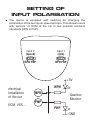
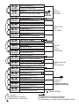
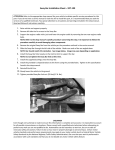
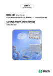
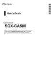
GEARBOX
MONITOR
MODEL NR. 1.1203
USER MANUAL
USER SAFETY
!
!
Before starting to drive with a mounted gearbox monitor you
need to make sure that:
=
=
=
the monitor does not limit field of vision of the driver;
monitor indications will not distract the driver;
“shift light” LED will not blind the driver, especially at night.
If any of the above conditions are not fulfilled, the location or
angle of the monitor has to be changed.
!
It is forbidden to base any significant decisions concerning safety
on the monitor indications, including:
=
=
selection of braking points;
selection or evaluation of driving speed.
LIABILITY DISLAIMER
!
The producer does not take any responsibility for damages which
may arise due to correct or incorrect operation of the monitor,
including: health and life of the driver and other people, damage
to property, including vehicles together with elements of
equipment.
!
Gearbox monitor is an indicator. The user must take into
consideration the possibility of inaccurate indications of the
device. Because of the above, the producer cannot be held
responsible for any damages to the vehicle which may be related
to the use of the monitor, including:
=
=
engine damage;
gearbox damage.
INTRODUCTION
!
The gearbox monitor is a microprocessor controlled device that
enables easier handling of the gearshift in sport cars and gives a
more sportive appearance to normal cars.
!
The main function of the gearbox monitor is to display the current
gear. The gear is calculated based on the speed and rpm. It also
displays a warning when the rpm exceedes the user defined limit.
!
This device works in cars with a speed sensor (VSS) and
electrically regulated ignition. Most of the cars with electronic fuel
injection (regardless of the kind of fuel) will meet these
requirements.
INSTALLATION
!
!
We suggest to install monitor after the start-up (setting of inputs
polarization and finding best position).
Find the optimal spot in the cockpit.
=
=
!
!
For racing purposes, when the information about the gear and
the rpm going beyond the limit is important, we suggest to place
the device in the field of view of the driver. Later test the position
during training.
For everyday use and for „on-boards“, we suggest to place the
monitor centrally, facing the driver or the camera.
Fix the device with glue or double-sided tape.
Lay the cable under the cockpit, next to the radio
=
We suggest to place the cable first temporarily and fix it only
after testing the monitors position during training. For
permanent fixation lead the cable through a small hole in the
cockpit.
!
connect the 4-wire cable of the monitor with the electrical system
of the car in the correct order as follows:
=
=
the BROWN wire to a grounding (for example grounding of the
radio)
the GREEN wire to the rpm signal (the rpm input in cockpit or
the rpm signal from the ECM or the signal from the electronic
ignition module)
Do not connect signals from other sources since it can cause
malfunction of the device.
=
=
the WHITE wire to the speed signal (input from the electronic
speedometer or the signal from the speedsensor VSS)
the YELLOW cable to the electric power supply +12V (for
example: radiomemory supply).
Power supply +12V should be connected to a circuit that is not
switched off by the car key. The power supply cannot be interrupted
during learning process (including engine off operation). Otherwise
the device will reset before the learnig data will be saved in
EEPROM (memory). After programming the supply voltage is not
necessary in standby mode.
!
The correctly connected gear shift monitor will display a „wave“
and the correct power supply will be confirmed with a sound.
ATTENTION!
=
=
You will find the nessesary circuits (rpm and speed inputs from
the ECM or cockpit) on the cars electric circuit diagram. In case
of doubt, let an electrician make the connections.
To avoid cutting of the electrical wires, connect the device with
the help of clamps.
SETTING UP THE DEVICE
!
!
The correctly connected gear shift monitor will display a „wave“
and an acoustic signal will be heard. Then the display will be
cleared and a r control sign will be shown. Now, the device is
ready to receive the rpm and speed signals.
Start the engine:
=
=
=
!
a rotating red wheel and a „humming“ sound signal that the
speed signal was wrongly connected to the rpm input. In such a
case change the rpm and speed connections;
no response from the device with the engine running means
that the rpm input was wrongly connected. Check and correct
the wiring of the signals and select correct polarisation of rpm
input. (info on the next page)
When you see the green wheel on the display - start driving
(move on):
=
=
!
a rotating green wheel and a „fanfare“ sound signal the correct
rpm signal connection;
„fanfare“ sound and the letter „n“ on the display signal the
readiness of the device;
a constantly spinning green wheel indicates a wrong speed
signal wiring. Check and correct the wiring of the speed signal
and select correct polarisation of the speed input. (info on the
next page).
Stop the car.
SETTING OF
INPUT POLARISATION
!
The device is equipped with switches for changing the
polarization of the two inputs: speed and rpm. This allows to work
with sensors, or ECM of the car in two possible electrical
standards (NPN or PNP).
input 2
(speed)
input 1
(rpm)
NPN PNP
NPN PNP
+5V
electrical
installation
of the car
ECM, VSS...
NPN
NPN
Gearbox
Monitor
PNP
PNP
GND
PROGRAMMING
THE DEVICE
The device will programm itself automaticaly during driving.
It will save all the gears and the maximall rpm limit.
The following suggestions will help you to programm the device fast
and easy and to use its full potential.
!
Put in the first gear, start driving, accelerate and wait untill the
number (1) appears on the display.
!
Put in the second gear and drive untill the number (2) appears on
the display.
!
!
!
!
!
!
!
Repeat for all the gears including the reverse gear.
During programming pay atention to the fact that the gears must
be programmed in the correct order
=
=
gear 1 and 2;
gear 3,4,5 (and 6 if present) and the reverse gear.
During programming of the gears (or while standing still), the
device will simultaneously store the rpm range. To set the rpm
limit accelerate the engine to the maximal rpm. The set rpm limit
will be used in the future, to signal gear changes.
Exceeding of the rpm limit will be signaled with r and a red LED.
Do not stop the engine until all the gears (5, reverse and 6 if
present) are programmed and the rpm limit is set.
When all the gears and the rpm limit are set and the engine is
turned off the programming is finished. The learning data is
stored in EEPROM.
After each power-up the data will be restored and monitor will be
ready to use.
!
!
!
ADVANTAGES
AND LIMITATIONS
Signalisation of the max. rpm - The defined maximal rpm will
be displayed early enough to give sufficient time for the gear
change. In unmodified cars we suggest to set the rpm limit at the
max rpm of the engine (cut-off). It enables the maximal use of the
engine's power, without the danger of loosing speed as a result of
cutting off the fuel supply.
Driving in the neutral gear - Due to the method of calculation
the device displays always the gear that corresponds to the
current speed/rpm ratio (even if you drive in neutral gear). The
effect is negligible during dynamic sportive driving. In special
situations, like braking with the left foot, one can use this effect to
pick the right moment to change gear without the clutch. This also
allows driving with a defect clutch.
Reverse gear- the device differentiates between the gears
based only on the ratio difference, without taking the direction
into account. That means that the reverse gear will be displayed
correctly only if the transmission difference between the 1 and
the reverse gear is greater then 2-3%. If the device signals 1
during the programming of the reverse gear change the accuracy
to 1% (see editing parameters option A.1.). If it does not make
any difference, you will be unable to differentiate between the first
and reverse gear.
SETUP OF
THE GEARBOX MONITOR
!
The following parameters can be adjusted:
=
=
=
=
Display brightness
Display color
Monitor working modus
Gear discretization accuracy
A reset is also possible. It allows new programming.
Change the parameters in the following way:
!
!
!
!
!
!
!
Turn off the engine.
Start the engine.
Immediately after the green wheel is displayed press the
acceleration pedal to go over the half of the max rpm. Then let it
go. The device should respond by showing a „wave“ on the
display and making a sound. The first blockade, that protects
from an unintended reprogramming, is now removed. (the upper
barr on the display).
Repeate the acceleration manouver. You will see a „wave“ on the
display and hear a sound again. The second blockade is
removed (the middle bar on the display).
Press the acceleration one more time. You see another „wave“
on the display and hear a sound. The last blockade is removed
(the lower bar on the display). Now the device goes into a
parameter-edit modus.
After all the blockades are removed, edit the parameter
according to the following algorithm.
The editing can be finished at any time by starting driving or
turning the engine off (in this case the new setup will be stored
only temporary - in cache memory - till power off).
S.y.
Set yes ?
r.y.
Edit Parameter ?
Editing of the parameter
Go to
parameter
Reset ?
reset yes ? Reset of all the saved values
b.3.
Brightness 3 ?
b.2.
Brightness 2 ?
b.1.
Brightness 1 ?
b.0.
Brightness 0 ?
C.F.
Full color range?
C.r.
Red color?
RESET
edit modus
and Exit
brightness 3? sets high brightness level
brightness 2? sets middle brightness level
brightness 1? sets low brightness level
Brightness set
go to
color editing
brightness 0? gears will not be displayed
color Full ? Color dependent on the rpm
Color set
Go to
working
modus editing
color red ? Set the red color
C.G.
Green color?
d.S.
Sport modus?
d.E.
Easy modus?
A.1.
Accuracy 1%
A.2.
Accuracy 2%
A.3.
Accuracy 3%
A.6.
Accuracy 6%
A.9.
Accuracy 9%
color Green? set the green color
display Sport ? displays „n“ when in neutral
display Easy ? „fade-in, fade-out“ gear display
Working modus set
go to
editing accuracy
Accuracy 1%? admissible tolerance 1%
Accuracy 2%? admissible tolerance 2%
Accuracy 3%? admissible tolerance 3%
Accuracy 6%? admissible tolerance 6%
Accuracy 9%? admissible tolerance 9%
No reaction
(acceptance) by the user
is signalled by a „humming“
Accuracy sett
„Fanfare“all parameters set
and stored in EEPROM
Factory settings
acceptance of the setting by the user
(pressing on the acceleration pedal)
is confirmed by a „wave“ and a modulated sound
ABSOLUTE MAXIMUM
RATINGS
Voltage of any inputs relative to GND . . . . . . . . . . . . . . . -0,7..+18V
O
Storeage temperature . . . . . . . . . . . . . . . . . . . . . . . . . -15..+60 C
Relative humidity . . . . . . . . . . . . . . . . . . . . . . . . . . . . . . . . 0..80%
Stresses above those listed under ‘Absolute
Maximum Ratings’ may cause permanent damage
to the device.
TECHNICAL DETAILS
Supply voltage . . . . . . . . . . . . . . . . . . . . . . . . . . . . 11,3 ... 14,8V=
O
Operating temperature . . . . . . . . . . . . . . . . . . . . . . . . -10 ... +50 C
Inputs (optically separated) . . . . . . . . . . . . . . . . . . . . . . Rin = 1,5k
Dimensions . . . . . . . . . . . . . . . . . . . . . . . . . . . . . . . . ~ 6 x 6 x 6 cm
For further information contact:
MAVI Digital Electronics
Tel.: +48 32 442 04 37
[email protected]
More info: www.mavi.com.pl