1
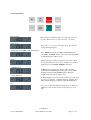
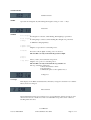
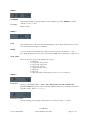
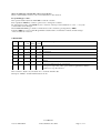
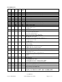
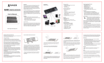
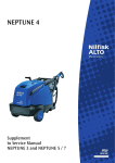
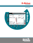
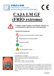
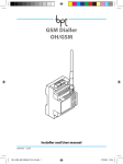
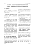
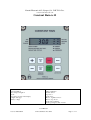
Nortoft Electronic A/S, Sejrupvej 38, DK 7323 Give.
www.nortoftelectronic.com
Constant Rain 6-12
Features:
Speed regulation
Pre- and post-irrigation
Clock
Stop time is shown in the display
Length of the pipe
Battery voltage
Charge regulation
Pressure sensor
Stop sensor
Speed sensor
Motor 1, regulation motor
Motor 2, stop motor
Slowly start of turbine
Slowly opening for inlet of water
User Manual
Ver.1.0 2015-06-01
© Nortoft Electronics 2015
Page 1 of 11
Short hand manual
+
DEPART
PREVOR-
STOP
MENU
-
ARRIVEE
POSTNACH-
START
RESET
PROG
Place machine:
Place machine at hydrant, Display shows the same start and
stop time. Wheel out hose to the end of lane. ( ex 218m )
Select Speed:
Press “+” or “-“ keys for the right speed. Speed can be
changed during Irrigation.
Start Irrigate, Select PRE- and POST Irrigation.
Press START For starting, For PRE- and POST Irrigation,
press PRE- and POST- irrigation key’s Bars indicating PRE
and POST Irrigation will be shown
Starting:
Turbine will start, as water pressure increases, after a while
the regulator finds the correct speed.. Irrigation is continued
until end of lane and STOP SENSOR is activated.
-PRE Irrigation
If PRE irrigation is activated, Turbine will stop again
immediately and PRE Irrigation takes place. Bar for PRE
Irrigating is flashing during PRE Irrigation. When pre
irrigation time has elapsed, turbine starts.
-POST Irrigation
If POST irrigation is activated, Turbine will stop at end, when
stop sensor is activated, and POST Irrigation will take place.
Bar for POST Irrigating is flashing during POST Irrigation.
Stop:
Stop sensor is activated, Turbine and Irrigation is shut down.
Machine is ready for disconnection and transport to a new
lane.
User Manual
Ver.1.0 2015-06-01
© Nortoft Electronics 2015
Page 2 of 11
MENU’s
Standard readout
Status bars
A Pre Irrigation
B Post Irrigation
C Charge
D Speed 1 Sensor
E Speed 2 Sensor
F Pressure
G Motor 1
H Motor 2
I Stop Sensor
Standard readout, Voltage low
Press the key MENU 1 time for showing menu 2
Press the key MENU 2 times for showing menu 3
Press the key MENU 3 times for showing the menu 4
( Only when analog pressure selected )
User Manual
Ver.1.0 2015-06-01
© Nortoft Electronics 2015
Page 3 of 11
Standard menu:
Standard readout
SPEED
Speed can be changed at any time during the irrigation, using “+” and “ –“ keys.
.
Status bars
STATUS
A Pre Irrigation
Pre Irrigation is selected, when flashing, Pre Irrigating is performed.
B Post Irrigation
Post Irrigating is selecteed, when flashing Post Irrigation is performed.
C Charge
SolarPanel is charging battary.
D Speed 1 Sensor
E Speed 2 Sensor
Magnets on speedsensor is activating sensor.
F Pressure
Pressure is ON, if digital of analog sensor is selected.
The machine can only work when the pressure is high.
G Motor 1
H Motor 2
Motor ( Valve ) has reached its end position.
I Stop Sensor
Magnet on stop sensor is activating sensor.
The machine can only work when the stop switch is on.
The stop switch has 3 functions:
1: Resets the distance counter.
2: Post-irrigation.
3: Inhibits the pulses to the regulator-motor.
Voltage low
Voltage
If the display shows LO in stead Status bars, the battery voltage is lower than 11.8 V and the
battery need to be charged.
Motor Current
The actual Current used by motor. The motor is stopped when the current exceeds 4.5 A. If
current exceeds 4.5A, and the motor has not reached their end position, there could be a
blocking inside the valve.
User Manual
Ver.1.0 2015-06-01
© Nortoft Electronics 2015
Page 4 of 11
MENU 2
DISTANCE
The remaining length of the pipe. Distance can be changed by pressing
with the “+” and “ –“ keys
PROG key 3 times,
Voltage
Battery voltage.
MENU 3
STOP
The reamining time for Pre, Post and normal Irrigating is shown. If the watch has been set, this
is the actual time when irrigation is finished.
WATCH
To set the watch press the PROG key 3 times, the time can then be set with the “+” and “ –“
keys. When the battery has been removed the watch is 00:00, and is remaining zero until it is set.
STOP CODE
The code shows the cause for the machine has stopped.
0 = Running
1 = Stopped by low pressure.
2 = Stopped by supervision.
3 = Stopped by stop key.
4 = Stopped by stop sensor.
5 = Not used
6 = Not used.
7 = The current has been interrupted or there is a lose connection.
MENU 4
Pressure
Shows pressure [BAR] ( 00.0 ) or [PSI] ( 000 ). The machine can only work when the
pressure is high. Has pressure not been selected ( Machinedata 14 = 0 ), irrigating is performed
regardless status ( Status F Pressure ).
Pressure Fault
If selected analog pressure gauge is dismounted or connection is fault, --.- is shown.
User Manual
Ver.1.0 2015-06-01
© Nortoft Electronics 2015
Page 5 of 11
START:
The turbine can only start if the magnet activates the stop sensor (or stop sensors), see Status: I Stop Sensor.
When the START key is pressed, the main valve opens. Next the by-pass valve closes (the turbine starts). If the
magnet does not activate the stop sensor, it is only the main valve that opens; this is used if the pressure should
be released before disconnecting the hose at the hydrant.
STOP:
When the magnet is removed from the stop sensor, the turbine stops and the main valve closes (opens at lowpressure stop). If post-irrigation is chosen, the turbine stops and after the post-irrigation time, the main valve
closes. If the key STOP is pressed the turbine stops and the main valve closes, regardless of post-irrigation.
SUPERVISION:
The CONSTANT RAIN has a built in system for supervision. The supervision starts to work, if for some reason
the machine irrigates at the same place longer than a specified time. This time is factory adjusted to 20 minutes,
see programming for changing this time. If it is set to 0 there is no supervision. If supervision of speed, data # 20
= 1, is selected, irrigation is stopped when speed was below 50% of selected, in specified time.
SPEED:
The speed is adjusted with the the ”+” and “ –“ keys, the speed first changes by steps of 0.1 m/h, then after 10
steps it changes by 1.0 m/h. The speed can be changed at any time, even while the machine is running. If the
time is checked it shows the new time for the remaining irrigation.
PRE-IRRIGATION:
Pressing the key PRE- can activate pre-irrigation. The time for pre-irrigation is calculated by the Program Rain
as 8 x the time for running 1 metre at the actual speed. The constant " 8 " ( constant no. 2 ) can be changed, see
programming. If the pre-irrigation is on, the machine starts and run 1/2 metre, then it stops for the pre-irrigation
time. By pressing the key START the pre-irrigation is cancelled. The magnet at the stop sensor should be in
place, before activating the pre-irrigation. Time for PRE- can be changed by ‘+’ or ‘-‘immediately after pressing
the PRE- key.
POST-IRRIGATION:
Post-irrigation can be activated by pressing the key POST- The time for post-irrigation is calculated by the
Program Rain as 8 x the time for running 1 metre at the actual speed. The constant " 8 " (constant no.3) can be
changed, see programming. The post-irrigation starts to count down when the magnet is removed from the stop
sensor. When the magnet is removed, the motor for speed regulation stops the turbine, after the post-irrigation
time the main valve closes, (opens at machines with stop for low pressure). At machines with only one motor for
speed regulation, the turbine starts after the post- irrigation time. By pressing the key START the postirrigation is cancelled. The magnet at the stop sensor should be in place, before activating the post-irrigation.
Time for POST- can be changed by ‘+’ or ‘-‘immediately after pressing the POST- key.
User Manual
Ver.1.0 2015-06-01
© Nortoft Electronics 2015
Page 6 of 11
There are different constants that can be set by the user.
These constant will be saved for years even if the battery is disconnected.
Programming procedure:
The speed should be adjusted to 11.1 m/h to reach the constants.
Press rapidly the PROG key 3 times to gain access to change the constants.
By subsequent pressing on the PROG key the constant no. will step forward. With the “+” and “ –“ keys the
constant value can be changed.
The CONSTANT RAIN goes back to normal and saves the constant by pressing the key MENU.
If the key MENU is not pressed the Program Rain switches back to normal after 1 minute, and the changes
of the constants are not saved.
CONSTANTS
Const
no.
Note
0
Fact.
Adj.
Min.
Value
100
-
1
Max.
Value
Description
- Enter 111 to reach machine data
Unused
2
8
1
15 Pre irrigation
3
8
1
15 Post irrigation
4
20
0
99 Supervision time [minutes]
5
6
Unused
0
0
2 0 = Stop for high pressure slow shutdown
1 = Stop for low pressure, valve opens and close again after 3 minutes
2 = Motor for stop disconnected
The constant no. 0 (the code) should be 111 to reach the machine data.
Then press " PROG " and the machine data is shown.
User Manual
Ver.1.0 2015-06-01
© Nortoft Electronics 2015
Page 7 of 11
MACHINE DATA
M.Data Note
no.
Fact.
Adj
Min. Max.
Value Value
Description
0
1
2
3
4
5
6
7
8
9
10
11
12
400
110
1850
12.00
200
10
4
0.89
3
160
2
100
1
0
40
500
5.00
50
5
1
0.70
0
0
1
0
0
1000
200
3000
30.00
1000
40
20
1.00
45
300
5
250
1
13
14
25
0
1
0
25
2
15
0
0
160.0
16
1
0
1
17
0
0
1
18
1
0
1
19
20
0
0
0
0
200
1
21
0
0
1
40
0
0
2
41
0.50
0.10
5.00
Analog Pressure
0 = ON/OFF Pressure switch
1 = Analog Pressure sensor – Display units [BAR]
2 = Analog Pressure sensor – Display units [PSI]
Sensor Offset voltage [V]
42
0.20
0.05
5.00
Sensor Gain voltage [V]/[BAR]
43
3.5
0.0
25.0
44
0.2
0.0
25.0
Pressure set point [BAR]
Set point for pressure OFF / ON
Pressure hysteresis [BAR]
Set point - 0.5 * Hysteresis for OFF ( Fact. 3.4 [BAR] = OFF )
Set point + 0.5 * Hysteresis for ON ( Fact. 3.6 [BAR] = ON )
Pipe length
[m]
Pipe diameter
[mm]
Reel drum diameter
[mm]
Windings pr. layer
Large drive sprocket
Small drive sprocket
Number of magnets
Ovality
First pulse to main valve
[sec]
Short pulses to main valve
[msec]
Time between short pulses
[sec]
Number of short pulses
Shut-down system,
0 = Only regulator motor
1 = 2 Motors
Preset of pulse to regulation motor at start [sec]
Pressure switch
0 = no pressure switch mounted
1 = pressure switch mounted
2= pressure switch mounted ( only start )
Distance between pulses 40.0-160.0 [mm]
roller Ø80 mm = 62.5 [mm]
0 = running by the formula ( M. data number 0 to 7 )
Speed sensor
0 = round sensor for roller
1 = double sensor
Opening of main valve
0 = fast opening
1 = slow opening
Pressure switch
0 = Main valve stay open at low pressure
1 = Main valve closes at low pressure
Delay from stopsensor to the regulator motor stops the turbine [sec].
Supervision of the right speed
0 = Supervision off.
1 = Supervision on ( 50 % of selected speed )
Meter or foot readings in the display
0 = Meter.
1 = Foot
User Manual
Ver.1.0 2015-06-01
© Nortoft Electronics 2015
Page 8 of 11
The Program Rain can be adjusted to 2 different types of sensors.
See, Machine Data #16 Sensor
One is a round sensor 60 mm in diameter and 4 sensors inside; this is only for rollers with one magnet. When the
battery is connected the display for 2 sec. shows S n.n0.
The other is a square sensor, or 2 separate sensors, this is used for rollers with more than one magnet and for
disk's with 1 to 20 magnets.
When the battery is connected the display for 2 sec.showed S n.n1.
Double sensor.
Round sensor
Constant Rain 6 18 Pol Connector
Cable connection
Version n.n1
Double sensor
1 + Battery
Brown
12 V
2 - Battery
Blue
3 + Solar Panel
Brown
4 - Solar Panel
Blue
5 Motor 1
Speed Regulation
6 Motor 1
Speed regulation
7 Speed Sensor 1 * Blue
8 Speed Sensor 1 * Black
9 Speed Sensor 2 * Yellow/green
10 Speed Sensor 2 * Brown
11 Stop Sensor
Blue or Brown
12 Stop Sensor
Blue or Brown
13 Motor 2
Stop Motor
14 Motor 2
Stop Motor
15 Pressure
Blue or Brown
16 Pressure
Blue or Brown
17 +Analog Pressure Brown
18 Analog Pressure White
-Analog Pressure Green
mount with 2, -Battery
Constant Rain 6
Cable connection Version n.n0 Round sensor
1 + Battery
Brown
12 V
2 - Battery
Blue
3 + Solar Panel
Brown
4 - Solar Panel
Blue
5 Motor 1
Speed Regulation
6 Motor 1
Speed regulation
7 Speed Sensor
Blue
8 Speed Sensor * Black
9 Speed Sensor * Yellow/green (Red)
10 Speed Sensor
Brown
11 Stop Sensor
Blue or Brown
12 Stop Sensor
Blue or Brown
13 Motor 2
Stop Motor
14 Motor 2
Stop Motor
15 Pressure
Blue or Brown
16 Pressure
Blue or Brown
17 +Analog Pressure Brown
18 Analog Pressure White
-Analog Pressure Green
mount with 2, -Battery
* If the distance counter count the wrong way,
the speed sensor should be turned.
* If the distance counter count the wrong way,
the cable on terminal 8 and 9 must be interchange.
Technical data
Size ( h*w*d)
Voltage
Current
Fuse
170*140*100
10-15V dc
4 mA ( Idle)
4.5A motor max current
5A Fast
User Manual
Ver.1.0 2015-06-01
© Nortoft Electronics 2015
Page 9 of 11
Fault localisation.
? The turbine can not start by pressing START. Pre-and post-irrigation can not take place.
Answer:
Magnet for stop-sensor is not on its place, or cable or sensor is damaged.
-
must be on when the magnet is on place, and it disappears when the magnet is
Stop sensor: The status
removed. A damaged cable can be repaired but absolutely watertight, but a new sensor and cable is recommend.
If pressure sensor is used there must be pressure on the water. The status
-
for pressure must be on.
? None figure in the display.
Answer:
Battery interrupts. Fuse inside the box is blown. The fuse is for wrong connection of + and - .
From the factory there are an extra fuse on a single fuse-holder on the printed circuit.
Fuse 5 A. Battery electric voltage 12 V. See menu 2.
? Distance meter is not correct and the speeds not correct.
Answer:
-
See after damaged cable or sensor. The 2 status
must during pulling out the tube appear as following: The
first appear the second appear the first disappear the second disappear. During retraction it must go in opposite
order. It is the same if a roller running on the tube measures the speed.
? Only maybe the half or 2/3 of the real length is counted up.
Answer:
The stop mechanism can be activated a short time by hopping of the tube or if the windings around the drum are
losing. It can cause the magnet removed from the stop sensor a short moment. It will set the counter to zero.
In spite of the meter of the tube is not correct the irrigator will run to the end and stop normal. But incorrect
speed depends of the incorrect registration of the actual layer.
If wanted the correct number of metre can be set in distance.
User Manual
Ver.1.0 2015-06-01
© Nortoft Electronics 2015
Page 10 of 11
The most used combination of different constants:
With constants factory adjusted the machine always will run. But there are different conditions from farm to
farm and there are also different wishes from the farmer. Therefore some constants can be adjusted for local
wishes.
1. Slowly start of turbine. Machine data no. 13. Adjust the to value to 4 sec to start.
Now the valve for control of speed will close about half and continue stepwise until the adjusted speed are
reached. Correct adjustment is: Continuously closing of the valve until the turbine is start running and
stepwise until adjusted speed are reached.
2. Slowly opening for inlet of water. Machine data no. 17. Set the value to 1. =
Opening for the water stepwise.
3. Only 1 motor for speed regulation. Machine data no. 12. Value 0.
Post irrigation must take place as following: When the stop sensor is activated only the retraction stop. After the
time for post irrigation the machine start again and run to the mechanic stop.
4. Start up of no. 2 machine when no. 1 machine reaches the stop.
Machine data no. 14. Value 2.
The machine must be equipped with adjustable pressure switch. Adjust the pressure switch to a point between
the normal pressure and the pressure when the pump will stop.
For instance: Normal pressure 7 bar and pressure for pump stop is 9 bar. Adjust the pressure switch to 8 bar on
both the machines. Start no. 1 machine as normal by pressing start. Set up no. 2 machine but press stop. When
no. 1 machine comes to slowly close down no. 2 machine will start up when the pressure reach 8 bar. Be attend
on that 10 m different on the field level is 1 bar.
5. Stop with low pressure and pressure switch mounted. Constant no. 6. Value 1.
Machine data no. 12 must be value 2. = Stop motor turns in opposite direction. It means that with the same
cable connection to the motor the valve will open for stop. After 2 minute the valve close again
Stop-sensor, stop-button and supervision can open the valve. But the pressure switch can not open the valve
User Manual
Ver.1.0 2015-06-01
© Nortoft Electronics 2015
Page 11 of 11