Download System
Transcript
Twido and Altivar with CANopen System User Guide 33003584.04 [source code] SEP 2006 Contents Application Source Code ...................................................................................................... 4 Typical Applications.............................................................................................................. 5 System................................................................................................................................... 6 Architecture ....................................................................................................................... 6 Installation ......................................................................................................................... 9 Hardware...............................................................................................................................................11 Software................................................................................................................................................16 Communication ......................................................................................................................................17 Implementation ................................................................................................................ 20 HMI .......................................................................................................................................................21 PLC.......................................................................................................................................................36 Data Communication........................................................................................................ 61 Devices .................................................................................................................................................65 Appendix ............................................................................................................................. 74 Detailed Component List .................................................................................................. 74 Component Protection Classes ........................................................................................ 77 Component Features ....................................................................................................... 78 Contact ................................................................................................................................ 81 Introduction This document is intended to provide a quick introduction to the described System. It is not intended to replace any specific product documentation. On the contrary, it offers additional information to the product documentation, for installing, configuring and starting up the system. A detailed functional description or the specification for a specific user application is not part of this document. Nevertheless, the document outlines some typical applications where the system might be implemented. Twido and Altivar with C ANopen_EN.doc Schneider Electric 2 Abbreviations Word / Expression AC Advantys Altivar (ATV) CANopen CB CoDeSys ConneXium DC EDS E-OFF, E-STOP Harmony HMI I/O IclA (ICLA) Lexium/Lexium05/LXM Magelis MB - SL Micro NIM Osiswitch PC Phaseo PLC Powersuite Premium Preventa PS1131 (CoDeSys) PS SE Sycon Telefast TesysU Twido TwidoSuite TwidoSoft Unity (Pro) Vijeo Designer VSD WxHxD XBT-L1000 Zelio ZelioSoft Twido and Altivar with C ANopen_EN.doc Signification Alternating Current SE product name for a family of I/O modules SE product name for a family of VSDs Name for a communications maschine bus system Circuit Breaker Hardware-independant IEC 61131-3 programming software SE product name for a Family of Transparent Factory devices Direct Current Electronic Data Sheet Emergency Off switch SE product name for a family of switches and indicators Human Machine Interface Input/Output SE product name for a compact drive SE product name for a family of servo-drives SE product name for a family of HMI-Devices SE name for a serial Modbus communications protocol SE product name for a middle range family of PLCs SE product name for a Network Interface Module SE product name for a family of position switches Personal Computer SE product name for a family of power supplies Programmable Logic Computer An SE software product for configuring drives SE product name for a middle range family of PLCs SE product name for a family of safety devices SE Product name for PLC programming software with CoDeSys Power Supply Schneider Electric SE product name of a Field bus programming software SE product name for a series of distributed I/O devices SE product name for a decentralised I/O System SE product name of a middle range family of PLCs SE Product name for a PLC programming software SE product name for a PLC programming software SE product name for a PLC programming software An SE software product for programming Magelis HMI devices Variable Speed Drive Dimensions : Width, Height and Depth An SE software product for programming Magelis HMI devices SE product name for a low range PLC family SE product name for a PLC programming software Schneider Electric 3 Application Source Code Introduction Examples of the source code and wiring diagrams used to attain the system function as described in this document can be downloaded from our website under this link. The example source code is in the form of configuration, application and import files. Use the appropriate software tool to either open or import the files. Extension AIW CNF CO CSV CTX DCF DIB DOC DOP EDS FEF GSD ISL PB PDF PRO PS2 RTF STU STX TLX TWD VDZ XEF ZM2 Twido and Altivar with C ANopen_EN.doc File Type Configuration File Configuration File CANopen definitions file Comma Seperated Values, Spreadsheet Device Configuration File Device Independent Bitmap Document file Project File Electronic Data Sheet – Device Definition Export file EDS file (Geraete Stamm Datei) Island file, project file Profibus definitions file Portable Document Format - document Project File Export file Rich Text File - document Project file Project file Project file Project file Project file Export file Project File Schneider Electric Software Tool Required Advantys Sycon Sycon Twidosoft Unity Advantys Sycon Microsoft Word Magelis XBTL Industrial standard PL7 Profibus Advantys Sycon Adobe Acrobat PS1131 - CoDeSys Powersuite export file Microsoft Word Unity Pro PL7 Twinline control tool TwidoSoft Vijeo Designer Unity Pro Zeliosoft 4 Typical Applications Introduction Here you will find a list of the typical applications where this system/subsystem can be applied: Industrial Small to middle sized automated machines De-centralised automated sub systems serving as components in large or middle sized machines Machines Packaging Machines and box folders Palette wrappers Food & Drug Drying Plants Conveyor ovens Application Description Packaging machines or Box folders. These machines are often used as feeder components in larger confectioning and filling systems. Wrappers for Palettes. These machines wrap palettes so that the layers of goods are securely held on the palette. These stand alone machines can be integrated into production lines. Drying plants and conveyor ovens. Used as Components in larger system where products need to be dried. Twido and Altivar with C ANopen_EN.doc Schneider Electric Eample 5 System Introduction The system chapter describes the architecture, the dimensions, the quantities and different types of components used within this system. Architecture General The PLC in this application is a Twido. The user can control the application using the Magelis HMI device. The motor drives, connected to the PLC via a CANopen bus, are of type Altivar 31. The example application includes two safety options; A tamper free emergeny off function supervised with a Preventa safety module and a second safety module to evaluate protective door sensors. Layout Twido and Altivar with C ANopen_EN.doc Schneider Electric 6 Components Hardware: Mains switch type Compact NSC100 sag protection and indicator Contactor GV2-L (Short Circuit protected) for the motor drives Motor drive type Altivar ATV31 with integrated CANopen interface Power circuit breakers of type Tesys K and Tesys D (LP1K und LC1D) Emergency off switch with rotation release (tamper free) Emergency off safety module of type Preventa XPSAC Power Supply Phaseo ABL7 Modular/Compact PLC TWIDO with CANopen module Compact, colour display HMI device Magelis XBT-G Buttons and indicators XB5 of type Harmony Style 5 Standard rotary current motors Software: Twidosuite Version 1.0 PowerSuite V2.3 Vijeo-Designer V4.4 Quantities of Components For a complete and detailed list of components, the quantities required and the order numbers, please refer to the components list at the rear of this document. Degree of Protection Not all the components in this configuration are designed to withstand the same environmental conditions. Some components may need additional protection, in the form of housings, depending on the environment in which you intend to use them. For exact environmental details of the individual components please refer to the appropriate user manual. Technical data Mains voltage Power requirement Drive power rating Motor brake Connection Safety Level Safety Notice As there are no moving mechanical parts in this application example, category 3 (according to EN954-1) has been selected as an optional safety level. However, the standard and level of safety you apply to your application is determined by your system design and the overall extent to which your system may be a hazard to people and machinery. 400V AC Approx. 11 kW 2x 0,37 kW, 2x 0,55 kW none 5x 2,5mm² (L1, L2, L3, N, PE) category 3 (optional) Whether or not safety category 3 should be applied to your system should be ascertained with a proper risk analysis. This document is not comprehensive for any systems using the given architecture and does not absolve users of their duty to uphold the safety requirements with respect to the equipment used in their systems or of compliance with either national or international safety laws and regulations. Twido and Altivar with C ANopen_EN.doc Schneider Electric 7 Dimensions The dimensions of the individual devices used; PLC, Drive, Power supply, etc. require a housing cabinet size of at least 800x600x300mm (WxHxD). The HMI display, illuminated indicators such as „SYSTEM ON“, „SYSTEM OFF“ or „ACKNOWLEDGE EMERGENCY OFF“ as well as the emergency off switch itself, can be built into the door of the control cabinet. Twido and Altivar with C ANopen_EN.doc Schneider Electric 8 Installation Introduction This chapter describes the steps necessary to set up the hardware and configure the software for the described application. Layout Note This document describes the implementation of a palette wrapper as a sub-system within a larger paletting system. The modules and I/O here listed are a representative cross section of the modules and indicators required to implement the application as defined in this document and will without doubt differ from your own specific application. Twido and Altivar with C ANopen_EN.doc Schneider Electric 9 PLC I/O Wiring Type Twido-PLC Inputs Twido-PLC Outputs Wiring Twido Twido Power supply Wiring Motor Drives ATV31 Twido and Altivar with C ANopen_EN.doc I/O I 0.0 I 0.1 I 0.2 I 0.3 I 0.4 I 0.5 I 0.6 I 0.7 I 0.8 I 0.9 I 0.10 I 0.11 Designation Not used, reserved for fast counters Not used, reserved for fast counters Emergency off OK Door Safety OK Magnetic CB Drive #1 OK Magnetic CB Drive #2 OK Magnetic CB Drive #3 OK Magnetic CB Drive #4 OK Pallet arriving (HW-indicator) Pallet on turntable in Stop position Turn turntable slowly Stop position turntable I I I I I I lower End position wrapping sled upper End position wrapping sled Wrapper arm activated Removal track ready (HW-indicator) Pallet was received (HW-indicator) Wrapping Torn 2.0 2.1 2.2 2.3 2.4 2.5 I 2.6 I 2.7 I 2.8 I 2.9 I 2.10 I 2.11 I 2.12 I 2.13 Q 0.0 (Trans) Q 0.1 (Trans) Q 0.2 Q 0.3 Q 0.4 Q 0.5 Q 0.6 Q 0.7 Optional: Detect Pallet Height Wrapper arm extended Wrapper arm retracted Cutter open Cutter closed Gap Control arrival Gap Control Departure Wrapping Minimum thickness Display - emergency off acknowledge Display - Safety door acknowledge Signal lamp red (error in system) Signal lamp green (running, Automatic) Signal lamp white (System on) Signal lamp blue (Safety door error) System on Wrapper is ready (HW-indicator) Q 3.0 Q 3.1 Q 3.2 Q 3.3 Com (Inputs) -V Com (+) Com 1 Com 2 Com 3 Pallet accepted (HW-indicator) Extend Wrapper arm Cut wrapping Pallet ready for departure (HW-indicator) 0V DC reference potential 0V DC reference potential +24V DC +24V DC +24V DC +24V DC No Status i.e. No digital or Analog I/O Schneider Electric 10 Hardware General The mains switch, including sag protection and indicator can be set up on a mounting plate. The components to be including in a housing, i.e. Twido-PLC, Phaseo-Power Supply, emergency off switch, circuit breaker, contactors, can be mounted (snap on) on a 35mm DIN rail. The motor drive can either be screwed directly to a mounting plate or, with the use of an adapter, also be mounted on a DIN rail. The emergency off, door safety actuator, signal column as well as the acknowledgment battery are designed for rear wall mounting. All switches (except the door safety sensor) can be mounted without their housings in a cabinet or cabinet door. The XB5 buttons and indicators can either be mounted in the front door of a housing with a 22mm cutout or mounted in an XALD housing for direct wall mounting. The wiring schemes for the individual components can be found in the detailed wiring diagram attached. Mains Switch NSC 100 Compact Emergency OFF switch for cabinet door mounting XB5AS844 + XB5AZ141 Incl. E-OFF label ZBY9330 Indicator Press Button (Series Harmony Style 5) XB5 Twido and Altivar with C ANopen_EN.doc Schneider Electric 11 
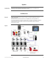
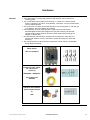
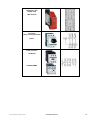
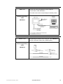
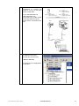
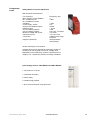
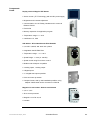
Emergency Off Safety relay XPS AC5121 Contactor (Short circuit protected) GV2-L Load contactor LC1D18P7 LP4K0601BW3 Twido and Altivar with C ANopen_EN.doc Schneider Electric 12 Power supply Phaseo ABL7RE2403 ABL7RE2405 PLC Twido Modular Device TWDLMDA20DRT PLC Twido Interface Module CANopen Master TWDNCO1M Twido and Altivar with C ANopen_EN.doc Schneider Electric 13 CANopen-TAP VW3CANTAP2 (the image shows a device with the end resistor switched off and 2 CAN cables attached) CANopen – Plug TSX CAN KCFD 180 T with integrated terminal resistor for linking to the Twido-CANopen-Master CANopen – Cable TSX CAN CA 50 Magelis HMI Display XBT-G2330 Twido and Altivar with C ANopen_EN.doc Schneider Electric 14 Motor Drive Altivar ATV31 ATV31 H037 N4 ATV31 H055 N4 Terminal Description Twido and Altivar with C ANopen_EN.doc Schneider Electric 15 Software General The main programming work lies in the programming of the Twido PLC, the configuration of the CANopen bus and creating the faceplates for the HMI display. Programming the Twido PLC is done using Twidosuite. Die HMI application on the Magelis XBT-G 2330 display is created using Vijeo Designer. Although the motor drives can be configured using the front panels on the drivers themselves, it is recommended that you use the PowerSuite tool. Powersuite not only offers you more comfort for the configuration but also offers possibilites for saving and archiving your configration. Not only does it allow to do a quick recovery, returning the motor drive to factory mode, it also allows you to test your configuration online and make online adjustments and optimisations during the test session. The software packet is delivered with the altivar Your PC must have the appropriate Microsft windows operating system installed: Windows 2000 or Windows XP. The software tools have the following default install paths: TwidoSuite: C:\Programs\Schneider Electric\TwidoSuite Vijeo-Designer: C:\Programs\Schneider Electric\VijeoDesigner PowerSuite: C:\Programs\Schneider Electric\PowerSuite Twido and Altivar with C ANopen_EN.doc Schneider Electric 16 Communication General This chapter describes the hardware used for data communications (CANopen) and the use of programming cables used in configuring the individual devices of the system. HMI <> Twido The data transfer between the Magelis-Terminal and the Twido-PLC is implemented with a Modbus connection. For this connection the communication cable XBTZG915 is required. The necessary Modbus drivers are included both in the software for the Magelis panel and Twido PLC. Magelis Communication Cable XBTZG915 Twido <> PC For programming the Twido PLC the programming cable TSXPCX1031 (serial) or TSXPCX3030 (USB) is required. Note: the switch integrated into the cable must be set to position 2. Port 1 on the PLC must be configured for point to point communication. Twido-Programming Cable TSX PCX 1031 (serial) or TSX PCX 3030 (USB) Twido and Altivar with C ANopen_EN.doc Schneider Electric 17 HMI <> PC The data communcation between the HMI XBTGT1000 and the dem PC during configuration is done using the communication cable XBTGZ915. This cable comes with the Vijeo-Designer software packet. XBTG-Programming Cable XBTGZ915 ATV31 <> PC Programming the Altivar is done using the cable VW3A8106 and the Powersuite cable RJ45<>SubD9 (black). ATV31-Programming Cable VW3A8106 Twido and Altivar with C ANopen_EN.doc Schneider Electric 18 CANopen Master Module CANopen TWDNCO1M The CANopen-InterfaceModule is plugged into the Twido PLC and has a Sub-D-9 CANopen connection CANopen Plug TSXCANKCDF90T Use this plug on the TWDNCO1M. Plug includes a terminal resistor. CANopen-Kabel TSXCANCD50 Flexibles Kabel CANopen-TAP VW3CANTAP2 Connection for 2 drives of type Altivar 31. Configuration port for use with PowerSuite. Terminal resisitor can be selected using the ON /OFF switch. The image shows the resistor set to OFF. CanOpen Branch Cable VW3CANRR1 Connects the TAP to the Altivar 31 with two RJ54 plugs. Twido and Altivar with C ANopen_EN.doc Schneider Electric 19 Implementation Introduction The implementation chapter describes all the steps necessary to initialise, configure to program and start-up the system. Function Start up and functional description 1. 2. 3. 4. 5. 6. 7. Switch on all fuses and contactors. The master switch is off. Acknowledge the emergency off Switch on at mains switch Check safety door(s) and acknowledge Wait for the red light to turn off You can now select automatic or manual mode on the HMI screen Manual Mode: Using the screen TEST you can select on control an individual moter drive. 8. Automatic Mode: Using the screen CONFIGURE you can adjust the speed parameters and the number of top and bottom wrapping layers. The button DEFAULT SETTINGS re-installs the default factory setup. 9. Select APPLICATION via the main menu to observe the individual steps of the process or start a simulation 10. Use the DIAGNOSE displays to control error messaging and observe the individual drive status. Layout Twido and Altivar with C ANopen_EN.doc Schneider Electric 20 HMI Introduction This section describes the steps needed to create the Magelis images. For this we use Vijeo Designer. Setting up the HMI is done as follows: the tool setup Create a new project Connect to HMI configure the driver Link variables Create variables Examples Download the project Example application The Tool Setup 1 Vijeo Designer has the following components: 1 - Navigator 2 - Info-Display 3 - Inspector 4 - Data list 5 - Feedback Zone 6 - Toolbox Create a new project 1 Twido and Altivar with C ANopen_EN.doc After starting Vijeo Designer, select Create New Project and press Next. Schneider Electric 21 2 Input a Project Name e.g. “Winder” and select: Project with Single Target You may enter a description or comment but it is not compulsory Press Next. 3 Select the target device Target Name: “Target1” Target Type: “XBTG Series“ XBTG Model: “XBTG2330” 4 The device has no Ethernet interface, so it requires no IP address. Here simply press Next and go to the next dialog.” Twido and Altivar with C ANopen_EN.doc Schneider Electric 22 5 The Magelis needs the correct driver to exchange data with the PLC. Use Add to go to the driver selection dialog and select a new driver. 6 In the New Driver dialog Select: Manufacturer: “Schneider Electric Industries SAS” Driver: “Modbus(RTU)” Equipment: „Modbus Device” confirm with OK. 7 Twido and Altivar with C ANopen_EN.doc After setting up the driver you can exit the dialog with Finish. Schneider Electric 23 8 Vijeo Designer now returns you to its work top, with an empty display and the project navigator A mouseclick on Target1 in the navigator brings up the properties inspector (or if the properties inspector is closed right mouseclick on Target1 and selecting Properties opens up the properties inspector) 9 Check the properties of the project and in particular the properties of the COM-port. It must be set to serial for the connection to work properly. Ensure that the COM port settings are correct (normally COM1 as default). Connect to HMI 1 Although downloading to the Magelis will not actually be performed now, you must connect the COM port of the PC with the Tool port on the Magelis to perform the download. Use the cable XBTZG9156 to make the connection. Twido and Altivar with C ANopen_EN.doc Schneider Electric 24 Configure the driver 1 For the communications to work you must set up the parameters in the Modbus RTU-Driver For this, right mouseclick on ModbusRTU01 in the Navigator and select Configuration... 2 In the Driver Configuration dialog, input: - COM2 - 19200 Baud - 8 Data bits - 1 Stop bit - No Parity Exit the dialog with OK. The configuration must match the port definition on the Twido. 3 In the Navigator you can rename the configuration to PLC with a right mouseclick on the name and selecting Rename. 4 Rightmouse click on PLC to go to the device configuration. In this configuration the HMI is slave, the PLC is master. Twido and Altivar with C ANopen_EN.doc Schneider Electric 25 5 In the Equipment Configuration dialog set the Slave Equipment Address to 2. and set the checkbox for IEC61131 Syntax you can leave the other inputs at their default values. Exit with OK. Link Variables 6 Acknowledge the confirmation for the IEC61131 Syntax with YES 1 As the variables have already been input in TwidoSuite (or some other Schneider product) Vijeo-Designer offers an option to link up to these variables. Select the Variables tab in the the Navigator. Right mouse click on the project name (here TARGET1) and select Link Variables in the pop-up menu Twido and Altivar with C ANopen_EN.doc Schneider Electric 26 2 In the Link Variables window give the path to the file, the type of file and the Equipment type (here as named above PLC) Select the file and click on Open 3 In this example the path was set to the TwidoSoft directory, the file type set to TwidoSoft and the equipment set to PLC. Then a Twido file (*.twd) was selected and opened. 4 Once the file was successfully opened you will be offered a selection list of the available variables Twido and Altivar with C ANopen_EN.doc Schneider Electric 27 5 Mark the variables you wish to link to and click on Add. 6 Linked variables are now deactivated with grey text. If you have finished linking the variables you require, exit the dialog with a click on Close. Twido and Altivar with C ANopen_EN.doc Schneider Electric 28 Create variables 7 All variables can now be viewed in the navigator on the Variables tab. 1 To create variables, click on the Tab variable in the navigator A right mouse click on Target1 opens up the pop-up menu to go to New Variable -> New… and the variable definition dialog. 2 To create a variable you must input a: Variable name Data type Data Source (External) Address in the PLC Device Address: Here you can address bits (%M..), memory words (%MW..) in the PLC. Twido and Altivar with C ANopen_EN.doc Schneider Electric 29 3 clicking on the Device Address opens up a dialog for the input of the address. PLC internal formats such as counters muss first be transferred to memory words before the Magelis can display them. Integers and Reals : 30001 + i and 40001 + I Discretes: 00001 + 10001 + 30001 + 40001 + i i i, i, and and j and j where „i“ represents the bit number or word number i.e. you address them with the appropriate offset. 4 Examples: PLC %M106 HMI 00001 + 106 => 00107 PLC %MW207 HMI 40001 + 207 => 40208 PLC %MW100 Bit5 HMI 40001 + 100, 5 40101,05 The image shows the variable Test with its attributes listed in the Property Inspector. Twido and Altivar with C ANopen_EN.doc Schneider Electric 30 Examples 1 Example: Insert Text Select the text tool in the tool bar. The toolbar displays the toolbox with tools for editing the display. 2 Example: Create Text With the text tool, position the text box on the display. You can adjust its size by „pulling“ on the box or by giving a value in the text editor dialog. Double click on the text box to open up the text editor dialog you can input the text to be displayed and define its size, font, etc. Twido and Altivar with C ANopen_EN.doc Schneider Electric 31 3 After inputting the text you can define/change the text characteristics in the Property Inspector 4 A right mouse click on the text object in the display leads to the animation. This is the same animation as seen in the property inspector (see image above) but in another format. Both formats contain the same attributes. Twido and Altivar with C ANopen_EN.doc Schneider Electric 32 Animation Properties: 5 Colour Position Value Visibility For the variable used to animate this object, you can either manually input the variable or click on the lightbulb icon to browse the variable list and select a variable. If you input an unknown variable it is shown in red – the variable has yet to be defined Once activated variables can be selected and their display format defined. If the value requires further processing before use, such as trigonomic functions, you can select these via the calculator icon. 6 Twido and Altivar with C ANopen_EN.doc Text and Graphics examples. Schneider Electric 33 Download the project 7 This picture shows the finished diagnostic screen with some animations and buttons 1 Before you download the project to the Magelis you must validate it With Validate All you can analyse your project. The feedback zone shows you the results of the analysis. You can invoke the project analysis using Build All too. 2 Downloading the project to the Magelis (HMI) Select the project in the Navigator. Use Build->Download All to transfer the project to the HMI device. The transfer is done using the configured protocol (serial in this case). The Vijeo Designer package contains a serial cable as standard. The download process is indicated with a progress bar. Twido and Altivar with C ANopen_EN.doc Schneider Electric 34 Example Application 1 The example application contains several user screens. The picture shows the main screen which, on clicking on the buttons, leads to further screens. This screen shows the language selection and drive mode etc. 2 To test individual drives click on Manual Mode in the above screen. In the screen that pops up click on the input fields in the columns Set Point Manual and input a value von 0..1500 (corresponds to 0..50Hz). Now select Manual Mode and hold down one of the green arrows to the right of a drive number. The drive starts up in the direction selected and the actual speed value is displayed. Releasing the button locks the drive again. Twido and Altivar with C ANopen_EN.doc Schneider Electric 35 PLC Introduction The PLC chapter describes the steps required for the initialisation, configuration and the source program required to fulfil the functions. The application program is produced using Twidosuite. Preconditions In order to proceed you require the following: Starting Twidosuite Twidosuite installed on your PC The Twidosuite example project The Twido PLC is connected to a power supply and switched on The PLC is connected to the PC with the programming cable (TSXPCX1031) 1 To start work with Twidosuite, click on: Programming Mode Use the language selection buttons to set the language for this session. 2 The start up screen for the main menu is displayed. With Create a new project you can start a new project. Twido and Altivar with C ANopen_EN.doc Schneider Electric 36 Create a new Project 1 Once Create a new Project is selected, enter a Project name and select the Directory path to save it. You can enter Project Information if required but it is not mandatory. Confirm with Create. Select the Hardware 1 Now go to Describe to configure the hardware. 2 In the configuration Workspace you will see a Twido PLC. In the Catalog on the RHS you can select the hardware/modules you wish to configure The Workspace offers you graphical documentation. Twido and Altivar with C ANopen_EN.doc Schneider Electric 37 3 In the Catalog, first select the correct type of Twido TWDLMDA20DRT. 4 Use Drag&Drop to drag the selection to the graphical image of the Twido. The grahical image will change to green. Drop the selected Twido while the mouse icon is in the green field. Twido and Altivar with C ANopen_EN.doc Schneider Electric 38 5 As next modules select the CANopen Master TWDNCO1M. Use Drag&Drop to place it to the right of the Twido PLC in the graphical image. 6 Now add the extra digital inputs module TWDDDI16DK Again, using drag&drop place it next to the CANopen Master. Finally add the digital outputs module TWDDDO8UT. Twido and Altivar with C ANopen_EN.doc Schneider Electric 39 7 Now add the Magelis Terminal XBTG2330 For this add the general Magelis Modbus element to the configuration. 8 The Workspace now shows a graphic display of the configured modules/devices. The connection HMI/PLC, via the Modbus interface, has still to be done. 9 To confgure the HMI connection, move the mouse icon over the HMI until the mouse icon changes to a screwdriver. Now a doubleclick opens up the configuration dialog. Give the device a Name and check that the default Protocol Modbus at Address 1 is offered. Confirm with OK. Twido and Altivar with C ANopen_EN.doc Schneider Electric 40 10 Name and Modbus address now appear in the graphic display next to the HMI device. 11 Now do the same for the PLC modbus interface. Position the mouse icon on the modbus interface of the PLC. When the mouse icon changes to a screwdriver, doubleclick to open up the configuration dialog. Change the Protocol type to Modbus and set the Address to 2. Confirm with OK. 12 Now connect the two devices in the graphics display by linking the white crosses that reperesent the linking points. To do this click on the white cross of one device and then the next so that the link is displayed. 13 After linking the devices you can give the network a name and set the baud rate by double clicking on the connecting line or the network box. In this case we use the default values. Twido and Altivar with C ANopen_EN.doc Schneider Electric 41 Hardware Configuration 1 For the hardware configuration select the main menu Program. 2 The screen shows the PLC rack. Note the menus on the RHS and bottom of the display area. Menus on the RHS are sub-menus to the main menu along the top. Twido SPS 1 You can now configure all the I/O variables for the PLC. To name the variables click on the Symbol column for a particular I/O and input the new name. 2 Spaces and special characters are not allowed in symbol names. If the variable is already in use in the program, the check box to the LHS is activated. 3 Twido and Altivar with C ANopen_EN.doc All symbol names are shown in uppercase. Schneider Electric 42 4 Changes are only made when the Apply button is pressed. If you try to exit the dialog without pressing Apply, you will be reminded. CANopen Master 5 Symbols entered in the configuration are automatically inserted into the variable list. 1 The next step is to configure the CANopen Master. Click on the CANopen module in the graphics image. 2 Click on Configure in the module configuration. 3 The CANopen Configuration Tool appears. Twido and Altivar with C ANopen_EN.doc Schneider Electric 43 4 In the Tab Network, double click on BASIC ATV31(V1.0) in the Catalogue to add an entry in the Slave list of the Network. Add another Slave with each double click. The row number(#) in the Network list is used as the CANopen Address. 5 Use the cursor keys to move slaves up or down in the list. Default entry for a slave is Supervision : None The default timeout for all slaves is 300msec. Set the supersvision to HeartBeat but leave the timeout at the default. 6 The default baud rate is 250 Kbit/s. For the example project, set it to 500 Kbit/s. Twido and Altivar with C ANopen_EN.doc Schneider Electric 44 7 Once you have entered all 4 drives in the slave list you can rename them e.g. Drive_1 … Drive_4 . To aid fault diagnosis, the entries are made so that Drive_1 is Slave 1, Drive 2 is Slave 2 etc. 8 The tab Linking lists the PDOs for the individual devices. This tab is for information only. You need to make no changes here 9 The Symbol tab lists all configured I/O Variables and their symbolic names. Die Variables for the Altivar31 are listed with standard names. These names can be changed if required. 10 To save the configuration click on Apply. Close the dialog with OK. Twido and Altivar with C ANopen_EN.doc Schneider Electric 45 Digital Input-Modul 11 Back in TwidoSuite, the configured Slaves are now listed in the entry for the CANopen Master. 1 click on the the digital input module in the graphic. The list of Inputs appears for the module. Symbol names can be input and applied. The variables are automatically inserted into the variable list Digital Output-Modul 1 click on the the digital output module in the graphic. The list of outputs appears for the module. Symbol names can be input and applied. The variables are automatically inserted into the variable list Drive Macros 1 To use the TwidoSuite macros for the Altivar 31, they must first be configured. To do this select: Program-> Configure-> Configure the Data-> Advanced object-> Macros drive Twido and Altivar with C ANopen_EN.doc Schneider Electric 46 2 For legibility, the macros are given the same number as the slave addresses, i.e. 1 – 4. 3 Select a macro to configure it by activating the check box. Set: Network: CANopen Network Address : 1 4 Reserve the memory words for the function in the entry D_Manager. In the example 30 words are reserved for macro drive 1, from MW30 to MW59, by giving the Start address and the number of words required 5 Setting the check box in the Symbols column allows the variables to be included in the variable list. 6 Click Apply to implement the drive configuration. In the example drives 14 are set up with MW30, MW60, MW90 and MW120 Twido and Altivar with C ANopen_EN.doc Schneider Electric 47 7 Change now to the main menu Describe and you will receive a request to resize the workspace. Acknowledge the message with OK. Resizing Workspace 8 TwidoSuite has increased the workspace and the configured drives and CANopen bus are now shown in the graphics. 1 You can re-position objects in the graphic to save space and for better legibility. Note: if you now print the image for documentation purposes empty fields are printed too. 2 Twido and Altivar with C ANopen_EN.doc To delete the empty fields, change the workspace format from 3x3 to 1x2. Schneider Electric 48 Variable List 3 The re-sized workspace. 1 In the variable list you can add symbols, give them a memory address and input a comment about them. 2 To add a symbol click on the insert icon. First enter the symbol name. Now you can add the address and a comment. 3 Twido and Altivar with C ANopen_EN.doc Use the different column headers as sort criteria to sort the table in alphabetical order. Schneider Electric 49 Create an application Program 1 Use the Edit Program function to go to the program editor. Starting a new program always begins with LADDER as the programming language. You can only view the program in LIST mode once the first rung has been completed and analysed. 2 Starting with an empty program, add a section. This will create a section with empty rungs. The first rung is marked in red on the LHS to denote that it has logical errors. 3 Click on the top of a rung to rename it. 4 You can also rename the section 5 Clicking on the rung changes its colour to green and indicates the current rung being edited. Clicking on an icon in the toolbar inserts the selected object at the first available place on the rung. So, you can add contacts… ….and outputs, etc. 6 Twido and Altivar with C ANopen_EN.doc Schneider Electric 50 7 To make a logical connection, simply mark the source and pull it to the destination. All possible connecting points are shown in green 8 Once a link has been inserted you can add a contact to form the logical OR. 9 To assign an object to an address or variable, click on the upper half of the object 10 The editor automatically recognises whether a rung is syntactically complete and marks it in yellow. The rung, however,has not yet been analysed. The Analyze program button is in the bottom right hand corner. 11 Twido and Altivar with C ANopen_EN.doc The Analysis is done for all contacts. Schneider Electric 51 12 If the analysis is error free, the yellow band changes to green. You can now change the display mode to LIST if you wish. 13 If erros are found, these are listed at the bottom of the edit field. Click on the arrow icon to enlarge the display. 14 A common error is No Start In Run Was Selected 15 To fix this, select: Program-> Configure-> Configure the behavior In the Configure the Behavior dialog select: Automatic start in Run This is an operation mode that causes the PLC to start up automatically on return of power after a power failure. Twido and Altivar with C ANopen_EN.doc Schneider Electric 52 Macro Drive 16 After restarting the analysis the error field is empty. 1 To use the macros for the drives, a second rung is added using the add a rung icon. 2 Insert an operation block for the macro. 3 To link the operation block to the macro drive input D_manager 1. D_manager is the macro function to access the drive and the 1 indicates Drive 1. 4 The space between D_manager and the 1 is mandatory. Twido and Altivar with C ANopen_EN.doc Schneider Electric 53 5 As the macro is already configured, the address field also contains the symbolic macro name D_MANAGER 1. The SHORT seen here must be exchanged for a control variable. You can now repeat this for the other macros: D_CLEAR_ERR D_RUN_FWD D_RUN_REV D_STOP und D_SELECT_SPEED . Save / export the project 1 To save the project select Save current project in the Project menu. In the Save current project window you can select the folder for the save, input the file name and designate the file Format. You can save the file as a normal Project file or as an Archive file. The Archive file has the advantage of being portable and is a single file. Twido and Altivar with C ANopen_EN.doc Schneider Electric 54 Open / Import a Project 1 To open a project use the Open an existing project function in the Project menu. In the open an existing project window select the medium : disk or Controller Give the file type under Format (for a project file: Project), select the folder and select the file you wish to open. When ready click on Open to open the project Twido and Altivar with C ANopen_EN.doc Schneider Electric 55 2 Proceed as above except for Import the file type is Archive. Connecting to the 1 Twido PLC To connect the PC to the Twido PLC select Program in the main menu, then Debug in the sub-menu to get access to the connect selection. 2 You can now either configure a new connection (see menu at bottom of window) or select a preconfigured connection. To connect click on OK. Twido and Altivar with C ANopen_EN.doc Schneider Electric 56 Download a Program 3 you will be shown a progress bar while Twidosuite establishes the connection. 1 After succesfully connecting to the Twido, Twidosuite compares the status of the project and the Twido PLC. Now you can either download your project or upload the contents of the PLC. 2 To download the project select: Transfer PC->controller and confirm with OK 3 If the Twido is already running it must be stopped first. Confirm with OK if you wish to proceed. 4 You will be shown a warning that the contents of the PLc are about to be overwritten confirm with OK to continue. 5 Twido and Altivar with C ANopen_EN.doc The download condition is indicated with a process bar. Schneider Electric 57 6 After a successful download, Twidosuite jumps automatically to the online viewing. 7 A control panel appears in the foreground. Here you can start and stop the PLC. The upper button extends the window, offering more PLC status information 8 If you start the PLC you will be asked to confirm the action If you wish to proceed with the start click on OK. 9 Twido and Altivar with C ANopen_EN.doc After successfully starting the PLC the RUN LED changes from yellow to green. Schneider Electric 58 10 Here the expanded window with the PLC in run mode. 11 If the online status window is closed, a click in the upper left hand corner of the main window opens it again. 12 The sub-menu Manage animation tables allows acces to animation tables. Twido and Altivar with C ANopen_EN.doc Schneider Electric 59 13 Twido and Altivar with C ANopen_EN.doc Use the project browser to navigate through the program sections. Schneider Electric 60 Data Communication Introduction This chapter describes the data transferred via the communcations bus (e.g. Modbus or CANopen) that is not bound directly with digital or analog hardware. The list Devices Concerned contains: The devices concerned Direction of Data flow symbolic name and Bus address of the device concerned. This application uses Modbus and CANopen busses. CANopen connects the following devices: A twido PLC on bus address 127 (fixed) 4 Altivar variable frequence drives, bus adresses 1..4 The Modbus connects: Magelis-Panel XBT-G, bus address 1 Twido PLC, bus address 2 Datalink Drive_1 <> PLC Datalink Drive_2 <> PLC Twido-PLC (CANopen-Master, #127) Altivar 31, Drive_1 (CANopen-Slave#1) Data Direction ATV -> PLC Address Name Index Designation %IWC1.0.0 D_STATUS_DRIVE_1 6041 Drivecom status register %IWC1.0.1 D_CONTROL_DRIVE_1 6044 Control effort %IWC1.0.2 D_IERROR_DRIVE_1 603F Error Code Data Direction PLC -> ATV Address Name Index Designation %QWC1.0.0 D_COMMAND_DRIVE_1 6040 Drivecom command register %QWC1.0.1 D_TARGET_DRIVE_1 6042 Target velocity Twido-PLC (CANopen-Master, #127) Altivar 31, Drive_2 (CANopen-Slave#2) Data Direction ATV -> PLC Address Name Index Designation %IWC1.1.0 D_STATUS_DRIVE_2 6041 Drivecom status register %IWC1.1.1 D_CONTROL_DRIVE_2 6044 Control effort %IWC1.1.2 D_IERROR_DRIVE_2 603F Error Code Data Direction PLC -> ATV Address Name Index Designation %QWC1.1.0 D_COMMAND_DRIVE_2 6040 Drivecom command register %QWC1.1.1 D_TARGET_DRIVE_2 6042 Target velocity Twido and Altivar with C ANopen_EN.doc Schneider Electric 61 Datalink Drive_3 <> PLC Datalink Drive_4 <> PLC Datalink HMI -> PLC Twido-PLC (CANopen-Master, #127) Altivar 31, Drive_3 (CANopen-Slave#3) Data Direction ATV -> PLC Address Name Index Designation %IWC1.2.0 D_STATUS_DRIVE_3 6041 Drivecom status register %IWC1.2.1 D_CONTROL_DRIVE_3 6044 Control effort %IWC1.2.2 D_IERROR_DRIVE_3 603F Error Code Data Direction PLC -> ATV Address Name Index Designation %QWC1.2.0 D_COMMAND_DRIVE_3 6040 Drivecom command register %QWC1.2.1 D_TARGET_DRIVE_3 6042 Target velocity Twido-PLC (CANopen-Master, #127) Altivar 31, Drive_4 (CANopen-Slave#4) Data Direction ATV -> PLC Address Name Index Designation %IWC1.3.0 D_STATUS_DRIVE_4 6041 Drivecom status register %IWC1.3.1 D_CONTROL_DRIVE_4 6044 Control effort %IWC1.3.2 D_IERROR_DRIVE_4 603F Error Code Data Direction PLC -> ATV Address Name Index Designation %QWC1.3.0 D_COMMAND_DRIVE_4 6040 Drivecom command register %QWC1.3.1 D_TARGET_DRIVE_4 6042 Target velocity Twido-PLC (Modbus #2) HMI Magelis XBT-G(Modbus #1) Data Direction HMI -> PLC Address Name Address Designation %M1 RESET 2 General_Reset %M3 AUTOMATIC_SEL 4 Automatic_Selection %M4 MANUAL_SEL 5 Manual_Selection %M7 SIMU_START 8 Auto_Start %M8 RESET_STEPS 9 Reset_steps %M16 CANOPEN_RESET 17 CANopen.Reset_CANopen %MW11:X1 MANUAL_START_FWD_ 40012:1 Drive01.Forward_manu DRIVE_1 %MW11:X2 MANUAL_START_BWD_ 40012:2 Drive01.Revers_manu DRIVE_1 %MW12:X1 MANUAL_START_FWD_ 40013:1 Drive02.Forward_manu DRIVE_2 %MW12:X2 MANUAL_START_BWD_ 40013:2 Drive02.Revers_manu DRIVE_2 %MW13:X1 MANUAL_START_FWD_ 40014:1 Drive03.Forward_manu DRIVE_3 %MW13:X2 MANUAL_START_BWD_ 40014:2 Drive03.Revers_manu DRIVE_3 %MW14:X1 MANUAL_START_FWD_ 40015:1 Drive04.Forward_manu DRIVE_4 %MW14:X2 MANUAL_START_BWD_ 40015:2 Drive04.Revers_manu DRIVE_4 Twido and Altivar with C ANopen_EN.doc Schneider Electric 62 Datalink PLC -> HMI Datalink PLC <> HMI Twido-PLC (Modbus #2) HMI Magelis XBT-G(Modbus #1) Data Direction PLC -> HMI Address Name Address Designation %M5 MANUAL_MODE 6 Manual_Mode %M6 AUTOMATIC_MODE 7 Automatic_Mode %M10 AUTO_START_STATE 11 Auto_Start_State %MW1 STEP_REGISTER 40002 Stepregister %MW33 D_ERROR_1 40034 Drive01.Errorcode %MW48 D_SELECT_SPEED_VAL_1 40049 Drive01.act_speed %MW63 D_ERROR_2 40064 Drive02.Errorcode %MW78 D_SELECT_SPEED_VAL_2 40079 Drive02.act_speed %MW93 D_ERROR_3 40094 Drive02.Errorcode %MW108 D_SELECT_SPEED_VAL_3 40109 Drive03.act_speed %MW123 D_ERROR_4 40124 Drive02.Errorcode %MW138 D_SELECT_SPEED_VAL_4 40139 Drive03.act_speed %MW11:X13 STOP_DRIVE_1 40012:13 Drive01.Stopped %MW11:X14 ERROR_DRIVE_1 40012:14 Drive01.Error_ATV %MW12:X13 STOP_DRIVE_2 40013:13 Drive02.Stopped %MW12:X14 ERROR_DRIVE_2 40013:14 Drive02.Error_ATV %MW13:X13 STOP_DRIVE_3 40014:13 Drive03.Stopped %MW13:X14 ERROR_DRIVE_3 40014:14 Drive03.Error_ATV %MW14:X13 STOP_DRIVE_4 40015:13 Drive04.Stopped %MW14:X14 ERROR_DRIVE_4 40015:14 Drive04.Error_ATV Twido-PLC (Modbus #2) HMI Magelis XBT-G(Modbus #1) Data Direction PLC -> HMI Address Name Address Designation %MW27:X0 ERROR_CO_MASTER 40028:0 CANopen.Error_Master %MW27:X1 ERROR_SLAVE_1 40028:1 CANopen.Error_Drive01 %MW27:X2 ERROR_SLAVE_2 40028:2 CANopen.Error_Drive02 %MW27:X3 ERROR_SLAVE_3 40028:3 CANopen.Error_Drive03 %MW27:X4 ERROR_SLAVE_4 40028:4 CANopen.Error_Drive04 %MW2:X0 STEP_0_ACTIVE 40003:0 Step_0 %MW2:X1 STEP_1_ACTIVE 40003:1 Step_1 %MW2:X2 STEP_2_ACTIVE 40003:2 Step_2 %MW2:X3 STEP_3_ACTIVE 40003:3 Step_3 %MW2:X4 STEP_4_ACTIVE 40003:4 Step_4 %MW2:X5 STEP_5_ACTIVE 40003:5 Step_5 %MW2:X6 STEP_6_ACTIVE 40003:6 Step_6 %MW2:X7 STEP_7_ACTIVE 40003:7 Step_7 %MW2:X8 STEP_8_ACTIVE 40003:8 Step_8 %MW2:X9 STEP_9_ACTIVE 40003:9 Step_9 %MW2:X10 STEP_10_ACTIVE 40003:10 Step_10 %MW2:X11 STEP_11_ACTIVE 40003:11 Step_11 %MW2:X12 STEP_11_ACTIVE 40003:12 Step_12 Twido and Altivar with C ANopen_EN.doc Schneider Electric 63 Datalink PLC <> HMI Twido-PLC (Modbus #2) HMI Magelis XBT-G(Modbus #1) Data Direction PLC <> HMI (read and write) Address Name Address Designation %MW15 DRIVE_1_MANU_VELO 40016 Drive01.Manu_Velo %MW16 DRIVE_2_MANU_VELO 40017 Drive02.Manu_Velo %MW17 DRIVE_3_MANU_VELO 40018 Drive03.Manu_Velo %MW18 DRIVE_4_MANU_VELO 40019 Drive04.Manu_Velo %MW19 AUTO_VELO_1 40020 Auto_velo_1 %MW20 AUTO_VELO_2 40021 Auto_velo_2 %MW21 AUTO_VELO_3 40022 Auto_velo_3 %MW22 AUTO_VELO_4 40023 Auto_velo_4 %MW23 AUTO_VELO_5 40024 Auto_velo_5 %MW151 BOTTOM_LAYERS_SET1 40152 Bottom_Layers_1_setpoint %MW152 BOTTOM_LAYERS_SET2 40153 Bottom_Layers_2_setpoint %MW153 TOP_LAYERS_SET 40154 Top_Layers_setpoint %MW154 BOTTOM_LAYERS_ACT1 40155 Bottom_Layers_1_actual %MW155 BOTTOM_LAYERS_ACT2 40156 Bottom_Layers_2_actual %MW156 TOP_LAYERS_ACT 40157 Top_Layers_actual Twido and Altivar with C ANopen_EN.doc Schneider Electric 64 Devices Introduction This chapter describes the steps required to initialise and configure the devices to attain the described system function. To do this we use the Powersuite software. General You can configure the altivars using the front panel on the device itself, however,using the software tool Powersuite has certain advantages: Save data to your hard drive and duplicate it Print documentation for your configuration Test and optimise the parameters online. The CD which accompanies the altivar drive not only holds documatation on the drive but also has a light version of powersuite to enable a quick set up of the drive. (note: the version of the factory setup actually delivered in your drive may be different to the version of the factory setup as found on the CD. If you wish to retain the factory setup as delivered in your drive you should first upload the factory setup from your drive to your PC) Start Program 1 If your Windows operating system is set up for it, the CD will start up automatically. The CD runs just like an online installation from a website. To install Powersuite click on PowerSuite to the right of the CD icon. 2 Follow the directions given and click on: click here to install the software Twido and Altivar with C ANopen_EN.doc Schneider Electric 65 3 Click on Open to confirm installation of the software. 4 Finally click on Finish to complete the installation. You can now start up Powersuite without restarting your PC. 5 You will find PowerSuite under the start menu: Programs-> Schneider Electric-> PowerSuite Here click on: Powersuite ATV31 6 to start the tool. The tools displays the standard screen on start up. In the menu Display click on Configurations Twido and Altivar with C ANopen_EN.doc Schneider Electric 66 7 Use the project browser on the left side of the window to view your project 8 To work with the drive you must create a new configuration. Click on ATV31 in the project broswer And then on: File->New->Configuration 9 A new window opens up. Here you can input a name for your configuration, a description and select the drive type – in our case ATV31H037N4. Close the dialog with OK. Twido and Altivar with C ANopen_EN.doc Schneider Electric 67 10 The name of the configuration now appears in the project browser below ATV31. Double click on the configuration name to open up a window to edit the configuration 11 To communicate with the Twido PLC via CANopen, the Altivar must know which address and baud rate to use. On the left hand side you see a list of parameter groups. Clicking on a group opens up an edit window with the parameters for that group. Select Communication in the parameter group Communication. 12 In the dialog that opens, insert the Addresses 1 to 4 und 500kbit/s baudrate for each. Save your changes using the menu File-> Save and close the configuration with File->close. Any further changes you wish to make to the configuration can be be done in the same way. Twido and Altivar with C ANopen_EN.doc Schneider Electric 68 13 For each Altivar you must input the motor data. To do this select: Motor Control-> Motor Characteristics 14 Input the motor data 15 After finishing the configuration you must now create a device that uses this configuration Click on devices in the project browser, then on: File->New->Device to go to the input dialog to create a new device. Twido and Altivar with C ANopen_EN.doc Schneider Electric 69 16 Give the device a name. – note, configuration and device names must be unique. And describe your device as you wish… serial number, physical position in system, document number etc. 17 Click on the tab Configuration. Here you can select your configuration From the list and assign it to your device. You can ignore the tab Communication for the moment Close the dialog with OK 18 Twido and Altivar with C ANopen_EN.doc The device name can now be seen in the project browser. You need only to mark the device name to select which configuration is to be downloaded to the drive Schneider Electric 70 19 Use the connecting set VW3A8106 to connect the COM on your PC to the RJ45 socket on the Drive. If you used CAN taps, be careful that the PC is connected to the middle socket on the tap and that only the target drive is connected to the tap. 20 Making sure the correct device is marked in the project browser first,use the menu Action->Transfer to download your configuration to the drive. Twido and Altivar with C ANopen_EN.doc Schneider Electric 71 21 Before the download proceeds you will receive a warning that must be read and acknowledged. 22 Powersuit displays a progress bar as it prepares for the download. 23 To successfully complete the download, Powersuite asks for confirmation. Repeat the procedure to configure the other drives but remember you must use different bus addresses for the other drives (so you must create new configurations with new devices). 24 Twido and Altivar with C ANopen_EN.doc To activate the downloaded bus parameters (address and baudrate) you must now switch off the controller (display goes off). On switching back on, the new parameters are ready. Schneider Electric 72 Manual Input using the Altivar Front Panel You can configure the ATV 31 by inputting the parameters using the front panel display and buttons on each Altivar, as follows: 1 The CANopen-Address and Baudrate can be input using the buttons on the front panel of the Altivar. 2 Using the buttons on the front panel, select the sub-menu Communication auszuwählen. 3 In the Communication submenu input the CANopen address in the parameter AdC0. In the example application the adresses for the four controlers are 1 to 4. 4 Also in the Communication sub-menu, in the parameter BdC0, set the baudrate to 500.0 (kBits). 5 Alternatively you can use the PowerSuite software to configure the CANopen addresses and baudrates. 6 To activate the downloaded bus parameters (address and baudrate) you must now switch off the controller (display goes off). On switching back on, the new parameters are ready. Twido and Altivar with C ANopen_EN.doc Schneider Electric 73 Appendix Detailed Component List Hardware-Components – Group 1: Mains Switch Pos. Amt. Description Part-Number 1.1 1 29003 1.2 1.3 1 1 1.4 1.5 1 1 1.6 1.7 1.8 1 1 1 Mains switch 3-pole 36 kA Compact NS100 N Connector cover 3-pole Switch Mounting TM16D 12-16 A 3pole Undervoltage Protector 230V Fuse Undervoltage release 1A (CAutomation) and 230V Contactor Actuator accessory 1 NC Locking device fixed Rotary drive with door switch (redyellow) Rev./ Vers. 29321 29035 29407 23725 29450 29371 29340 Hardware-Components – Group 2: Emergency Stop Pos. Amt. Description Part-Number 2.1 2.2 2.3 1 1 1 XB5AS844 XB5AZ141 ZBY9330 2.4 2.5 2.6 2.7 1 1 1 2 2.8 2.9 2.6 1 1 1 Mushroom switch red-yellow (E-Off) Contact block for E-OFF switch, 2NÖ E-OFF Sign, red-yellow, 60mm diameter Emergency Off Switch, Tamper free Preventa Safety Relay Fuse for Safety, 1P, C2A Redundant Contactors 18A 24V control circuit Acknowledge/Indicator Safety Einfachtastergehäuse Switch Housing Rev./ Vers. XALK178G XPSAC5121 23726 LC1D18BD XB5AW-36B5 XALD01 XALD01 Hardware-Components – Group 3: Door Safety Pos. Amt. Description Part-Number 3.1 3.2 3.3 3.4 3.5 1 1 1 1 1 Preventa Safety Relay Door Safety Switch Actuator door Safety Acknowledge/Indicator Safety Switch Housing XPSAC5121 XCSA502 XCSZ02 XB5AW-36B5 XALD01 Twido and Altivar with C ANopen_EN.doc Schneider Electric Rev./ Vers. 74 Hardware-Components – Group 4: Display and Indicators Pos. Amt. Description Part-Number 4.1 4.2 4.3 4.4 4.5 4.6 1 1 1 1 1 1 XVBC11 XVBC02 XVBC21 XVBC2B4 XVBC2B6 XVBC2B7 4.7 1 4.8 1 Signal Column, connector element Signal Column, tube Connector element Signal element red (System Fault) Signal element blue (Door Safety) Signal element white (PLC on, mains on) Signal element green (Drives Running, System On) Double switch housing Rev./ Vers. XVBC2B3 XALD02 Hardware-Components – Group 5: Automation Components Pos. Amt. Description Part-Number 5.1 5.2 1 1 Primary Fuse for PLC 1P,C1A Twido PLC Modular 5.3 5.4 1 1 CanOpen-Card CanOpen-Plug 5.5 5.6 2 4 Branch socket CANopen CAN Bus cable 1 m 23725 TWDLMDA20DR T TWDNCO1M TSXCANKCDF 90TP VW3CANTAP2 VW3CANCARR1 Rev./ Vers. Hardware-Components – Group 6: Magelis HMI Pos. Amt. Description Part-Number 6.1 1 23725 6.2 1 6.3 1 Circuit Breaker fused for HMI 1P, C1A Magelis Panel XBT-G 2330, 5,7", Colour, with Ethernet Interface cable to Twido Rev./ Vers. XBTG2330 PCX1031 Hardware-Components – Group 7: 24-Volt Power supply Pos. Amt. Description Part-Number 7.1 7.2 1 1 24516 ABL7RE2403 7.3 7.4 1 1 Main fuse 24V/3A, 2P, 1DA Power Supply 240 VAC 1phase , 24VDC 3A Primary fuse 24V/5A, 2P, D1,5 A Power supply 240 VAC 1phase, 24VDC5A Twido and Altivar with C ANopen_EN.doc Schneider Electric Rev./ Vers. 23728 ABL7RE2405 75 Hardware-Components – Group 8: Drives and Power Pos. Amt. Description Part-Number 8.1 8.2 8.3 8.4 8.5 8.6 8.7 2 2 4 2 2 4 4/8 Magnetic circuit breaker 2,5A Magnetic circuit breaker 4,0A Switch cover Altivar Drive 0,37 kW 3~ Altivar Drive 0,55 kW 3~ ATV31 Adapter for DIN rail contactor 6A (AC3), 1xNC GV2L07 GV2L08 GVAE11 ATV31H037N4 ATV31H055N4 VW3A31852 LP4K0601BW3 Rev./ Vers. 1.7 1.7 Software-Components – Group 9 Pos. Amt. 9.1 1 9.2 1 9.3 1 9.4 1 9.5 1 9.6 1 Description TwidoSuite Programming Software incl. Cable Twido Programming and HMI Communication cable Programming software for Magelis XBT-G Programming cable Magelis Configurationsoftware PowerSuite ATV31 Altivar-Set PC connection accessories Part-Number Rev./ Vers. TWDBTFU10EF 01.00 TSXPCX1031 VijeoDesigner 4.4 XBTZG915 CD with the ATV31 VW3A8106 Control Cabinet Components – Group 10 (SAREL) Pos. Amt. 10.1 1 10.2 10.3 10.4 10.5 1 2 2 Twido and Altivar with C ANopen_EN.doc 1 Description Part-Number Cabinet, 800x600x300mm (HxBxD, with mounting plate, Sarel) Fuse for Fan, 2P, C2A fan, with filter, 230V, 56 m³/h (Sarel) Filter for fan (Sarel) Thermostat for Fan, 0..60°C (Sarel) Schneider Electric Rev./ Vers. ENN83357 23747 ENN17901 ENN17911 ENN17562 76 Component Protection Classes Positioning Protection class Cabinet Component In Field, On site IP54 E-Off switch Emergency off switch housing Mains Switch, with or without undervoltage protection and integrated indicator Rotating Door handle for master switch contactor LC1D** und LP4K** Contactors and fuses, all types Phaseo Power supply E-Off safey switches XPSAC*** Twido PLC and expansion modules Magelis XBTG Touch panel, all types Altivar 31 Drive, 3phase, 380/500V AC, all types CANopen TAPS Switch series „Harmony“ in housing Filter und Filterfan Fan-Thermostat Twido and Altivar with C ANopen_EN.doc Schneider Electric IP65 IP67 Front IP55 X inside IP65 IP20 X X X X X X X X X X X X X X IP66 IP40 X 77 Component Features Components PLC Twido This example uses a Twido modular PLC with Twidosuite software and programmiing cable set (TWDLMDA20DRT+ TWDBTFU10EF + TSXPCX1031): 24VDC 12 digital inputs 8 digital relay outputs extensible up to 7 modules (analog- und communications modules also available) 2 Programming Languages: Contact plan (COP) Statement list (STL) Pre-defined functions: Drum control Fast Counters up to 5kHz Very Fast counters up to 20 kHz Frequency measuring 1..20 kHz Reserved Memory for LIFO/FIFO-processing PWM-/PLS-Outputs External PLC-Start PID-controller CANopen master module TWDNCO1M Master Module for Twido PLCs with: Control of up to 16 Slaves (Depends on number of PDOs/SDOs) Baudrates 125 / 250 / 500 kBit/s Slave watchdog with Node Guarding or Heartbeat Configuration tool integrated in Twidosuite Bus configuring via Modul Rear wall on the PLC Integrated macros for quick installation Slim Format (30mm width) Plugable contacts for power supply Configuration by PLC during switch on Twido and Altivar with C ANopen_EN.doc Schneider Electric 78 Components contd. Safety Module: Preventa XPSAF5130 Main technical characteristics: For monitoring Max. category accord. EN954-1 No. of safety circuits No. of additional circuits Indicators Power supply AC/DC Synchro time between inputs Response time AC-15 breaking capacity DC-13 breaking capacity Minimum voltage and current Dimensions (mm) Connection Degree of protection Emergency stop 4 3 N/O 3 LED 24V Infinite < 40 ms C300 24V/1.5A - L/R 50ms 17V/10mA 114 x 22,5 x 99 Captive screw-clamp terminals IP20 (terminals) IP40 (casing) Generic description of the product Preventa XPS security light barrier monitoring module for monitoring circuits to protect access to a danger zone. Depending on the model they meet the requirements of a category 2 or 4 (maximum) solution according to EN954-1. Power Supply Phaseo: ABL7RE2403 and ABL7RE2405 100..240V AC / 24V DC 3A with 5A secondary Narrow fitting Parallel wiring possible Short circuit and power surge protected Twido and Altivar with C ANopen_EN.doc Schneider Electric 79 Components Contd. Display terminal Magelis XBT-G2330 Sensor screen ( TFT-Technology) with 24V DC power supply Brightness and Contrast adjustment Communication via Uni-Telway, Modbus and in cases via Ethernet TCP/IP Flat Profile Memory expansion for application program Temperature range: 0..+ 50°C Certificates: UL, CSA VSD Altivar: ATV31H037N4 and ATV31H055N4 0,37 kW / 0,55kW, 380..500V AC 3 phase Integriated class B EMC Filter Temperature range: - 10..+ 50°C Speed Range: 1 to 20 (0...200 Hz) Speed control using Flow Vector control Modbus and CANopen compatible 2 analog inputs, 1 analog output 6 Digital inputs 2 / 3 digital stati outputs possible Drive and motor protection Compact format, side by side installation possible, using adapter VW3A11852 can be mounted on a DIN rail Magnetic Circuit breaker: GV2L07 and GV2L08 2,5 A / 4,0 A Short circuit protected Magnetic cut off at 33,5 A lockable Twido and Altivar with C ANopen_EN.doc Schneider Electric 80 Contact Author Schneider Electric GmbH Machines and Process Architectures Schneider Electric GmbH Steinheimer Strasse 117 D - 63500 Seligenstadt Germany Twido and Altivar with CANopen_EN.doc Phone E-mail +49 6182 81 2555 [email protected] As standards, specifications and designs change from time to time, please ask for confirmation of the information given in this publication. 81