1
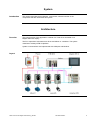
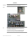
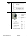
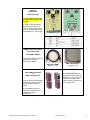
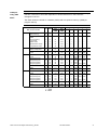
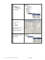
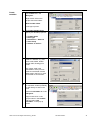
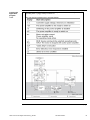
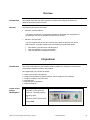
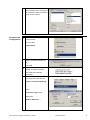
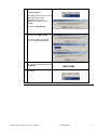
Twido and Lexium Magelis and Advantys System User Guide 33003565.04 [source code] SEP 2006 Contents Application Source Code.......................................................................................................... 4 Typical applications.................................................................................................................. 5 System .............................................................................................................................. 6 Architecture ....................................................................................................................... 6 Installation ......................................................................................................................... 9 Hardware...............................................................................................................................................10 Software................................................................................................................................................18 Communication ......................................................................................................................................19 Implementation ................................................................................................................ 26 Communication ....................................................................................................................................27 HMI .......................................................................................................................................................32 PLC.......................................................................................................................................................49 Devices .................................................................................................................................................66 Performance ..........................................................................................................................................86 Appendix ............................................................................................................................... 87 Detailed Component List .................................................................................................. 87 Component Protection Classes ........................................................................................ 88 Component Features ....................................................................................................... 89 Contact.................................................................................................................................. 91 Introduction This document is intended to provide a quick introduction to the described System. It is not intended to replace any specific product documentation. On the contrary, it offers additional information to the product documentation, for installing, configuring and starting up the system. A detailed functional description or the specification for a specific user application is not part of this document. Nevertheless, the document outlines some typical applications where the system might be implemented. Twido and Lexium Magelis and Advantys_EN.doc Schneider Electric 2 Abbreviations Word / Expression AC Advantys Altivar (ATV) CANopen CB CoDeSys ConneXium DC EDS E-OFF, E-STOP Harmony HMI I/O IclA (ICLA) Lexium/Lexium05/LXM Magelis MB - SL Micro NIM Osiswitch PC Phaseo PLC Powersuite Premium Preventa PS1131 (CoDeSys) PS SE Sycon Telefast TesysU Twido TwidoSoft TwidoSuite Unity (Pro) Vijeo Designer VSD WxHxD XBT-L1000 Zelio ZelioSoft Twido and Lexium Magelis and Advantys_EN.doc Signification Alternating Current SE product name for a family of I/O modules SE product name for a family of VSDs Name for a communications machine bus system Circuit Breaker Hardware-independent IEC 61131-3 programming software SE product name for a Family of Transparent Factory devices Direct Current Electronic Data Sheet Emergency Off switch SE product name for a family of switches and indicators Human Machine Interface Input/Output SE product name for a compact drive SE product name for a family of servo-drives SE product name for a family of HMI-Devices SE name for a serial Modbus communications protocol SE product name for a middle range family of PLCs SE product name for a Network Interface Module SE product name for a family of position switches Personal Computer SE product name for a family of power supplies Programmable Logic Computer An SE software product for configuring drives SE product name for a middle range family of PLCs SE product name for a family of safety devices SE Product name for PLC programming software with CoDeSys Power Supply Schneider Electric SE product name of a Field bus programming software SE product name for a series of distributed I/O devices SE product name for a decentralised I/O System SE product name of a middle range family of PLCs SE product name for a PLC programming software SE product name for a PLC programming software SE product name for a PLC programming software An SE software product for programming Magelis HMI devices Variable Speed Drive Dimensions : Width, Height and Depth An SE software product for programming Magelis HMI devices SE product name for a low range PLC family SE product name for a PLC programming software Schneider Electric 3 Application Source Code Introduction Examples of the source code used to attain the system function as described in this document can be downloaded from our website under this link. The example source code is in the form of configuration, application and import files. Use the appropriate software tool to either open or import the files. Extension AIW CNF CO CSV CTX DCF DIB DOC DOP EDS FEF GSD ISL PB PDF PRO PS2 RTF SPA STU STX TLX TWD VDZ XEF XPR ZM2 File Type Configuration file Configuration File CANopen definitions file Comma Seperated Values, Spreadsheet Device Configuration File Device Independent Bitmap Document file Project File Electronic Data Sheet – Device Definition Export file EDS file (Geraete Stamm Datei) Island file, project file Profibus definitions file Portable Document Format - document Project file Export file Rich Text File - document Schneider Product Archive Project file Project file Project file Project file Project file Export file Project file Project file Twido and Lexium Magelis and Advantys_EN.doc Software Tool Required Advantys Sycon Sycon Twidosoft Unity Advantys Sycon Microsoft Word Magelis XBTL Industrial standard PL7 Profibus Advantys Sycon Adobe Acrobat PS1131 - CoDeSys Powersuite Microsoft Word TwidoSuite Unity Pro PL7 Twinline control tool TwidoSoft Vijeo Designer Unity Pro TwidoSuite Zeliosoft Schneider Electric 4 Typical applications Introduction Here you will find a list of the typical applications, and their market segments, where this system or subsystem can be applied: Industrial Small to middle sized automated machines De-centralised automated sub systems serving as components in large or middle sized machines Machines Packaging Machines and box folders Conveyors Application Description Packaging machines In the packaging industry, for labeling, packaging, filling and palletizing goods Special-purpose machines Used on small specialpurpose machines for assembly, processing, cutting operations, etc. (e.g. food preparation, automated assembly, wood machining). Material conveyors Used in connection with transportation tasks that involve “pick and place” operations. Twido and Lexium Magelis and Advantys_EN.doc Schneider Electric Example 5 System Introduction This section describes the architecture, components, size and number of the components that are used within this system. Architecture Overview The control section of this application consists of a Twido PLC servicable via a Magelis HMI user display. The PLC supervises Lexium05 servo drives and Altivar 31 controllers. The system contains an Advantys STB I/O platform. System communcations are implemented with CANopen and Modbus. Layout Twido and Lexium Magelis and Advantys_EN.doc Schneider Electric 6 Components Hardware: Twido (PLC) Phaseo (power supply) Lexium05 (drive control) Altivar 31 (motor drive) Advantys STB (remote I/O) Magelis XBTG (HMI) TwidoSoft 3.2 (PLC) Advantys configuration software ver. 2.00 (remote I/O) Vijeo-Designer ver. 4.3 (HMI) PowerSuite 2.3 (Lexium05 and Altivar 31) Software: Quantities of Components For a complete and detailed list of components, the quantities required and the order numbers, please refer to the components list at the rear of this document. Degree of Protection Not all the components in this configuration are designed to withstand the same environmental conditions. Some components may need additional protection, in the form of housings, depending on the environment in which you intend to use them. For environmental details of the individual components please refer to the list in the appendix of this document and the appropriate user manual. Technical Data Mains voltage Power requirement Drive power rating Motor brake Connection Safety Level Safety Notice The standard and level of safety you apply to your application is determined by your system design and the overall extent to which your system may be a hazard to people and machinery. 230V AC ~ 3.0 kW 2x 0,75 kW, 2x 0,18 kW none 3 x 2,5mm² (L1, L2, L3, N, PE) none As the aim of this document is to detail the bus communication between the individual devices, no safety category has been selected or recommended. Whether or not the above safety category should be applied to your system should be ascertained with a proper risk analysis. This document is not comprehensive for any systems using the given architecture and does not absolve users of their duty to uphold the safety requirements with respect to the equipment used in their systems or of compliance with either national or international safety laws and regulations Twido and Lexium Magelis and Advantys_EN.doc Schneider Electric 7 Dimensions The dimensions of the individual devices used; PLC, Drive, Power supply, etc. require a housing cabinet size of at least 1000x600x300 mm (WxHxD). The HMI display and illuminated indicators can be built into the door of the housing. Twido and Lexium Magelis and Advantys_EN.doc Schneider Electric 8 Installation Introduction This chapter describes the steps necessary to set up the hardware and configure the software required to fulfil the described function of the application. Layout Note The configuration of this application has not been developed for any special actual use. It is intended to show how the system components work together as a unit. The components that are listed are a cross-section of the components needed for control and display in possible applications. This document does not claim to be comprehensive and does not absolve users from their duty to check the safety requirements of their equipment and to ensure compliance with the relevant national or international standards and regulations. Twido and Lexium Magelis and Advantys_EN.doc Schneider Electric 9 Hardware General For assembly purposes, the Twido, power supply and Advantys STB require a tophat rail. The other devices can be attached directly to the mounting plate. A 230 V AC wiring is used between the main switch, power supply and VSD. A 24 V DC wiring is used between the power supply, PLC, HMI and VSD control unit. There are other cables from the power cables (ATV and LXM) and feedback cables (only LXM) between the motor and the VSD. Components Master switch VCF-02GE Power supply ABL7RE2403 Continued on next page Twido and Lexium Magelis and Advantys_EN.doc Schneider Electric 10 Components contd. Twido PLC TWDLMDA40DTK 1 2 3 4 5 6 7 8 9 Hinged cover Extension connector Analog potentiometer Serial port 1 Module cover 24 V DC power supply terminals Analog voltage supply connector LEDs I/O terminals Twido PLC TWDLMDA40DTK Power supply Drive Controller ATV31 incl. PS and motor connection ATV31H018M2 Twido and Lexium Magelis and Advantys_EN.doc Schneider Electric 11 Drive Controller Connections ATV31 incl. PS and motor connection ATV31H018M2 Lexium05 Servo Drive LXM05AD10M2 Lexium05 Servo Drive LXM05AD10M2 Power connections (see T1) Twido and Lexium Magelis and Advantys_EN.doc Schneider Electric 12 Lexium05 Servo Drive LXM05AD10M2 Connection for Motors Lexium05 Servo Drive LXM05AD10M2 Overview of signal connections Twido and Lexium Magelis and Advantys_EN.doc Schneider Electric 13 Lexium05 Servo Drive LXM05AD10M2 Motor encoder Lexium05 Servo Drive LXM05AD10M2 24V power supply HBC Holding brake control Twido and Lexium Magelis and Advantys_EN.doc Schneider Electric 14 Wiring for field bus control, NO secure hold Lexium05 Servo Drive LXM05AD10M2 Terminals 33-39 must be connected. The motor brake (if present) must be connected via a holding brake control (HBC) Use the RJ45 terminal for CANopen. Servomotor BSH0702P02A2A Twido and Lexium Magelis and Advantys_EN.doc Schneider Electric 15 Power Cable 3 m VW3 M5 101R30 Feedback Cable 3 m VW3 M8 101R30 HMI Magelis XBT-G2330 Advantys STB Twido and Lexium Magelis and Advantys_EN.doc Schneider Electric 16 Advantys STB CANopen Bus adapter STB NCO 2212 Advantys STB Field Power supply STB PDT 3100 Note: the power supply to the inputs and outputs can be individually switched (e.g. for E-OFF) Twido and Lexium Magelis and Advantys_EN.doc 1 2 3 4 +24 VDC sensor bus power –24 VDC return line of sensor power supply +24 VDC actuator bus power –24 VDC return line of actuator power supply Schneider Electric 17 Software General The major software components involve the programming of the Twido PLC, including its CANopen configuration, and the creation of the HMI displays. Twidosoft is used to program the PLC. Vijeo Designer is used to create the HMI application for the Magelis XBT-G 2330 display. The Advantys configuration software is used to configure the Advantys STB I/O platform. Although the Lexium 05 and Altivar 31 can be configured using their front panels, for more comfort Powersuite is used. Powersuite not only facilitates the configuration of the devices but also offers the possibility of archiving and documenting the configuration. Archiving offers considerable advantages for maintenance and updating. The software can also be used to optimise the parameters online. In order to use the software your PC must have one of the following Microsoft Windows operating systems: Windows 2000 or Windows XP The software is installed on your PC under the following default paths: Twidosoft C:\Programme\Schneider Electric\TwidoSoft Vijeo-Designer C:\Programme\Schneider Electric\VijeoDesigner Advantys Configuration Software C:\Programme\Schneider Electric\Advantys PowerSuite C:\Programme\Schneider Electric\PowerSuite Twido and Lexium Magelis and Advantys_EN.doc Schneider Electric 18 Communication General The buses below are used for communication between devices: CANopen Modbus CANopen is used for communication at field bus level between the Twido PLC, the Lexium 05 and Altivar 31 drive controllers and the remote Advantys I/O platform. Should the PLC be reset, e.g. using “Reset Communication”, the parameters are reset to the factory values. These must be re-initialised using SDOs via CANopen. Modbus is used between the Magelis graphic touch panel (HMI) and the Twido PLC. Twido PLC The following module extensions and cables are required: 1. TWD NOZ 485D RS485 Expansion To connect the HMI with the PLC use cable XBTZ968 2. TWD LMDA 40DTK Twido-SPS Use cable TSX PCX 1031 to make the serial connection from the PC to the PLC. Use Twidosoft to program the PLC 3. TWD NC01M CANopen extension The standard CANopen plugs and cables are used. Twido and Lexium Magelis and Advantys_EN.doc Schneider Electric 19 HMI Magelis XBT-G2330 XBTZ968 XBTZG999 Communication cables for PLC including adapter. XBTZG915 Serial communication cable to PC (with Vijeo Designer). The Ethernet interface can be used as an alternative. Twido and Lexium Magelis and Advantys_EN.doc Schneider Electric 20 Advantys STB Programming cable STB XCA 4002 For connection to the serial interface of a PC with Advantys software. Advantys STB CANopen – Bus adapter STB NCO 2212 CANopen Fieldbus connection Twido and Lexium Magelis and Advantys_EN.doc Schneider Electric 21 Advantys STB CANopen bus adapter The rotary switches on the STB NCO 2212 CANopen NIM are used to set the network node address and the Advantys STB island’s baud rate. 1. Disconnect the island’s power supply. STB NCO 2212 CANopen baud rate 2. Set the lower rotary switch to any position between 9 and 0 (baud rate setting is marked). 3. Select the baud rate you wish to use for fieldbus communication. Select an appropriate baud-rate setting for your system and network requirements. 0 - 10,000 bps 4 - 250,000 bps 1 - 20,000 bps 5 - 500,000 bps 2 - 50,000 bps 6 - 800,000 bps 3 - 125,000 bps 7 - 1 Mbps In this example we have selected setting 5 (500,000 bps). 4. Turn the upper rotary switch to the position corresponding to the baud rate you have selected (e.g., 5). 5. Power up your island to use the new settings. The NIM only reads the rotary-switch settings on powerup. Advantys STB CANopen bus adapter STB NCO 2212 The rotary switches on the STB NCO 2212 CANopen NIM are used to set the network node address and the Advantys STB island’s baud rate. 1. Be sure to set the required baud rate (following the procedure described above) before setting the network node address. CANopen address 2. Disconnect the island’s power supply. 3. Select a network node address that is available in your fieldbus network. 4. Set the lower rotary switch to the position corresponding to the units of the required node address. For network node address 7, the lower switch would be set to 7. 5. Set the upper rotary switch to the position corresponding to the ten's and hundred's of the required node address. For network node address 7, the upper switch would be set to 0. 6. Switch on Advantys STB. The NIM only reads the rotary-switch settings on power-up. Twido and Lexium Magelis and Advantys_EN.doc Schneider Electric 22 Connection cable set for PowerSuite VW3 A8106 You will need the RS232 to RS485 adapter and the PowerSuite cable for the connection between the PC and the PowerSuite software and VSDs or servos. CANopen junction box VW3 CAN TAP2 Twido and Lexium Magelis and Advantys_EN.doc Schneider Electric 23 CANopen junction box VW3 CAN TAP2 For this application example, the slide switch must be set to OFF. If, unlike in this application, the junction box does not have an outgoing CANopen bus, the line terminator must be activated (i.e., set to ON). CANopen pre-assembled connection cable VW3 CAN CARRxx This cable is used to connect the junction box to the ATV31 and LXM05. VW3 CAN CARR03 (length: 0.3 m) VW3 CAN CARR1 (length: 1.0 m) CANopen connector VW3 CAN KCDF 90TP or VW3 CAN KCDF 90T This connector (with terminal resistor) is used for the link to the Advantys STB I/O island. At the end of the bus, the terminating resistor must be activated. To do this, set the switch to ON and the bus cable must be connected to the incoming side. It is advisable to have at least one connector with a CANopen analyser connection Twido and Lexium Magelis and Advantys_EN.doc Schneider Electric 24 CANopen connector assignment VW3 CAN KCDF xxxx CANopen cable TCX CAN Cx yy The cable is available in various versions (x): Standard No Flame Heavy Duty and various lengths (yy): 50,100, 300 m. Twido and Lexium Magelis and Advantys_EN.doc Schneider Electric 25 Implementation Introduction This chapter describes how to initialize, parameterize, program, and start up the system. Function Switching on and Functional description 1. After the power is switched on, all devices run through the initialization stage and the PLC starts the communication. The status bar displays system information. In this application, Manual mode (via HMI) is implemented 2. On the BUS screen, the status of the CANopen bus can be viewed. Use the buttons RESET NODE and TO OPERAT to reset and restart the communications. 3. The drives can be controlled using the appropriate display screens. Use the button RAMP to start an automatic speed cycle for all the drives 4. If an error occurs, the error number is displayed on the ALARM screen. The user can look up the description of the error in the operating manual. Layout Twido and Lexium Magelis and Advantys_EN.doc Schneider Electric 26 Communication Introduction This chapter describes the data passed via the communications bus (e.g. Modbus Plus or TCP/IP) that is not bound directly with digital or analog hardware. The list contains: Device Links The device links Direction of data flow symbolic name and Bus address of the device concerned. The Modbus and CANopen bus systems are used in this application. The following devices are networked via CANopen: - A Twido PLC, bus address 127 (fixed,master) Two Lexium05 servo drives, bus addresses 3 and 4 two Altivar 31 variable speed drives, bus addresses 5 and 6 One Advantys STB I/O island, bus address 7 Two devices are connected via Modbus: - CANopen Addresses Magelis panel XBT-G, bus address 1 Twido PLC, bus addresses 2 Twido-PLC is CANopen-Master Device 1. Lexium 05 2. Lexium 05 1. Altivar 31 2. Altivar 31 Advantys STB CANopen Address 3 4 5 6 7 The Baud rate is 500 kb/sec. Heartbeat is used to monitor the devices Twido and Lexium Magelis and Advantys_EN.doc Schneider Electric 27 CANopen COB-ID Data Link PLC <> LXM05 Data Link PLC <> ATV31 Data Link PLC <> STB Data Direction Device --> PLC (TPDO) Device 1.PDO 2.PDO 3.PDO 4.PDO 5.PDO 6.PDO 1. LXM05 183 ----483 2. LXM05 184 ----484 1. ATV31 --694 2. ATV31 --695 Advantys STB 187 287 Data Direction PLC --> Device (RPDO) Device 1.PDO 2.PDO 3.PDO 4.PDO 5.PDO 6.PDO 1. LXM05 203 ----503 2. LXM05 204 ----504 1. ATV31 --684 2. ATV31 --685 Advantys STB 207 208 Twido (CANopen-Master) Data Direction PLC <-- LXM (TPDO) 1.LXM 2.LXM %IWC1.0.0 %IWC1.2.0 %IWCD1.1.0 %IWCD1.3.0 %IWCD1.1.2 %IWCD1.3.2 Data Direction PLC --> LXM (RPDO) 1.LXM 2.LXM %QWC1.0.0 %QWC1.2.0 %QWCD1.1.0 %QWCD1.3.0 %QWCD1.1.2 %QWCD1.3.2 Lexium 05 (CANopen-Slave) Twido (CANopen-Master) Data Direction PLC <-- ATV (TPDO) 1.ATV 2.ATV %IWC1.4.0 %IWC1.5.0 %IWC1.4.1 %IWC1.5.1 %IWC1.4.2 %IWC1.5.2 Data Direction PLC --> ATV (RPDO) 1.ATV 2.ATV %QWC1.5.0 %QWC1.5.0 %QWC1.5.1 %QWC1.5.1 Altivar 31 (CANopen-Slave) Twido (CANopen-Master) Data Direction PLC <-- STB (TPDO) Address Name %IWC1.6.0 STB_IN_DI1 %IWC1.6.1 STB_IN_DI2 %IWC1.6.2 STB_IN_DI3 %IWC1.6.3 STB_IN_DI4 %IWC1.6.4 STB_IN_DI5 %IWC1.6.5 STB_IN_DI6 %IWC1.7.0 STB_IN_AI1 %IWC1.7.1 STB_IN_AI2 Data Direction PLC --> STB (RPDO) Address Name %QWC1.6.0 STB_OUT_DO1 %QWC1.7.0 STB_OUT_AO1 %QWC1.7.1 STB_OUT_AO2 Advantys STB (CANopen-Slave) Twido and Lexium Magelis and Advantys_EN.doc Index 6041 606B 6064 Designation Drivecom status register Velocity actual value Position actual value Index 6040 60FF 607A Designation Drivecom command reg. Target velocity Target position Index 6041 6044 603F Designation Drivecom status register Velocity actual value Error Code Index Designation 6040 Drivecom command reg. 60FF Target velocity Designation Digital Input Block Digital Input Block Digital Input Block Digital Input Block Digital Input Block Digital Input Block Analog Input Block Analog Input Block Designation Digital Output Block Analog Output Block Analog Output Block Schneider Electric 28 General Adressing The PLC example program uses different hardware, discretes and memory words. The following list contains keys to aid the understanding of the addressing system used. Type Address Comment Digital Inputs %I0.0 ... %I0.23 TWD_IN_DI00 ... TWD_IN_DI023 Digital Outputs %Q0.0 ... %Q0.15 TWD_OUT_DO00 ... TWD_OUT_DO15 Analog Inputs %IW2.0 ... %IW2.1 TWD_IN_AI1 ... TWD_IN_AI2 Analog Outputs %QW3.0 TWD_OUT_AO1 Internal Word %MW 0 ... 3000 max. possible address Constant Word %KW 0 ... 256 max. possible address Internal Doubleword %MD 0 ... 2999 max. possible address Constant Doubleword %KD 0 ... 255 max. possible address Internal %MF 0 ... 2999 max. possible address %KF 0 ... 255 max. possible address CANopen Inputs %IWC... see table above CANopen Outputs %QWC... see table above Floating Point Constant Floating Point Twido and Lexium Magelis and Advantys_EN.doc Schneider Electric 29 CANopen Function CAN_CMD Twidosoft provides the function CAN_CMD for access to the CANopen Interface. This function allows control of the CANopen bus (e.g. Reset Node) and transfer of SDOs to a specific device on the network. The parameters for the commands are forwarded using memory words (%MWx). The following table describes what action is taken when the parameters are given a particular value (%MWx to %MWx+5). Twido and Lexium Magelis and Advantys_EN.doc Schneider Electric 30 CANopen CAN_CMD The following table lists the SDOs used in the application. Only one SDO is active at any one time. The order of invocation depends on the active devices on the bus and is managed in the PLC. SDOs The initial values are stored as constants (%KW) and are copied to memory (%MW) at program start-up. CANopen SDO Communication Memory r/w SDO Spare SDO e.g.. Spare SDO e.g.. Init to PreOp (Reset Communication) to Init mode (Reset Node) Operational to PreOp to Operational mode r w STB 1. 2. from %KW ----- from %MW 409 415 s 3. 21 s s s 4. 5. 6. Status Analog value Status Analog value Inhibit Inhibit r w r w 1. LXM Inhibit Inhibit Ramp Start (ACC) Ramp Start (ACC) Ramp Stop (DEC) Ramp Stop (DEC) Mode Mode Error 2. LXM Inhibit Inhibit Ramp Start (ACC) Ramp Start (ACC) Ramp Stop (DEC) Ramp Stop (DEC) Mode Mode Error General Initial Value in Word x 1. 2. 3. 4. 5. 6. 421 1 0 --- --- --- --- 27 33 39 427 433 439 1 2 2 1 0 1 ------- ------- ------- ------- 7. 8. 9. 10. 45 51 57 63 445 451 457 463 3 4 3 4 7 7 7 7 6423 6423 1801 1802 00 00 03 03 r w r w r w r w r 11. 12. 13. 14. 15. 16. 17. 18. 19. 69 75 81 87 93 99 105 111 117 469 475 481 487 493 499 505 511 517 3 4 3 4 3 4 3 4 3 3 3 3 3 3 3 3 3 3 1803 1803 6083 6083 6084 6084 6060 6060 603F 03 02 03 02 2000 --00 04 2000 --00 04 2000 00 02 --00 01 00 02 --- r w r w r w r w r 20. 21. 22. 23. 24. 25. 26. 27. 28. 123 129 135 141 147 153 159 165 171 523 529 535 541 547 553 559 565 571 3 4 3 4 3 4 3 4 3 4 4 4 4 4 4 4 4 4 1803 1803 6083 6083 6084 6084 6060 6060 603F 03 02 03 02 2000 --00 04 2000 --00 04 2000 00 02 --00 01 00 02 --- 02 --01 1 02 02 2000 s - System r - read w - schreiben write Twido and Lexium Magelis and Advantys_EN.doc Schneider Electric 31 HMI Introduction This section describes how to set up the screens for the Magelis HMI. Vijeo Designer is the software used. Proceed as follows to integrate the HMI: Vijeo Designer environment 1 Create a new project Set Up the communication Create variables Create a screen CANopen Status display Build and Download Project Application summary The Vijeo Designer environment consists of: 1. Navigator 2. Information display 3. Inspector 4. Data list 5. Feedback area 6. Toolbox Twido and Lexium Magelis and Advantys_EN.doc Schneider Electric 32 Create a new project 1 Start up Vijeo designer and select Create new project. Continue with Next>. 2 Assign a project name and, if required, enter a description or comment. Continue with Next>. 3 Select the target device used: Target name: Hmi2twd Target type: XBTG Series Model: XBTG2330 Continue with Next>. Twido and Lexium Magelis and Advantys_EN.doc Schneider Electric 33 4 To use the Ethernet interface you must enter an Ethernet address for the target device. If required, enter IP address Subnet Mask Default Gateway Continue with Next>. 5 To exchange data with other devices the Magelis HMI needs a communications driver. Attach the new driver by clicking on Add. 6 In the New Driver dialog select: Manufacturer:Schneider Electric Industries SAS Driver: Modbus (RTU) Equipment: Modbus Equipment Exit with OK to accept the driver. Twido and Lexium Magelis and Advantys_EN.doc Schneider Electric 34 7 The new driver is attached. Exit with Finish to complete the project creation. Twido and Lexium Magelis and Advantys_EN.doc Schneider Electric 35 Set Up the Communication 1 Once the project has been created Vijeo Designer displays the working environment. 2 Right mouse click on the platform name in the Navigator to view the project attributes in the Property Inspector. Select the download setting for the connection between PC and Magelis. Ensure that the setting shows Ethernet and that the IPAddress and SubnetMask are valid. Twido and Lexium Magelis and Advantys_EN.doc Schneider Electric 36 3 To configure the Modbus driver select: I/O Manager -> ModbusRTU01 ->Configuration.... in the Navigator. 4 Driver configuration: COM1 (RS485) Even 8 data bits 1 stop bit 19200 baud The configuration must be the same as in the PLC. Enter the correct values and exit the dialog with OK. 5 To configure the device, right mouse click on the connection in the Navigator and select: Configuration.. Twido and Lexium Magelis and Advantys_EN.doc Schneider Electric 37 6 In the Equipment Configuration dialog set the slave equipment address to 2. The Preferred Frame Length is 16. Click the box for IEC61131 Syntax and select 0-based(default) so that the same Addressing Mode is used as in the PLC (%MWxxx etc.). Exit with OK. 7 You can Rename the Navigator entries if you wish. Twido and Lexium Magelis and Advantys_EN.doc Schneider Electric 38 Create variables 1 To create a variable, switch to the Variable tab in the Navigator. Right mouse click on the project name and select : New Variable->New.. in the pop-up menu. 2 In the New Variable dialog specify the variable properties: 3 Variable Name Data Type Data Source – External Scan Group Address in the PLC The variable address is any valid PLC address, e.g. bits %M, words %MW, doublewords %MD, floating point %MF. Any values used in the visualisation of the process must be transferred to these data types in the PLC in order for the HMI to access them. 4 Variables can also be imported or exported. another possibility to link directly to them in the PLC Select the Variables tab in the Navigator. Right mouse click on the project name in the Variable tab and select Link Variables.. in the pop-up menu Twido and Lexium Magelis and Advantys_EN.doc Schneider Electric 39 5 In the Link Variables window give the path to the file, the type of file (*.TWD) and the Equipment (here as named above Twido). Select the file and click on Open. 6 Once the file was successfully opened you will be offered a selection list of the available variables Mark the variables you wish to link to by clicking on the check box for that variable To facilitate legibility the variable names in the PLC and HMI should be the same. Click on Variables that keep the same name. Once you have made your selection. Click on Add to link to the variables and then Close to close the dialog. 7 If you wish to link to more variables later you can use the New Variables from Equipment.. function. Twido and Lexium Magelis and Advantys_EN.doc Schneider Electric 40 8 All variables can now be viewed in the Navigator on the Variables tab. Twido and Lexium Magelis and Advantys_EN.doc Schneider Electric 41 Create a screen As an example of how to create an animated screen, the creation of a numerical object is described here. The method is similar for creating other objects in the screen. Example 1 The different object types can be selected and inserted into the screen using the toolbar 2 First mark the position and size of the object on the screen. 3 Define the attributes for the object Name Data Type Variable Style Font Style and size, The Variable can be edited manually or selected from a list by clicking on the bulb icon at end on the edit box. Note: if the given variable is undefined, it is indicated with red text. Continued on next page Twido and Lexium Magelis and Advantys_EN.doc Schneider Electric 42 Create a screen contd. 4 The variable to use for the animation can be selected from the list with a double click. Extra functions, e.g. the negation of the value of the variable, can be selected using the calculator icon in the toolbar. 5 Here the finished screen with text fields, animated variables and control buttons. 6 Every object on the screen has attributes that can be viewed in the Property Inspector. To view the attributes of an object, use right mouse click on the object. Twido and Lexium Magelis and Advantys_EN.doc Schneider Electric 43 CANopen Status Display 1 The status of the CANopen devices is available in the PLC as a value from 1 to 15. We want to show this value as text on a HMI screen. To do this select the object Message Display and position it on the HMI screen. 2 First, in the Variable Properties dialog for the variable set the I/O setting to BIN and 16 bits. and in the attributes In the Message Display Settings input the variable name and set States to 16. Now click on the New Resource icon (at the end of the color Resource field). 3 In the New Resource dialog, input: Color name: CANopenColor Text Name: CANopenStatus Num.of states: 16 Check the box for Message Display. Data Type: integer and exit with OK. Twido and Lexium Magelis and Advantys_EN.doc Schneider Electric 44 4 The CANopenColor defines different colours to be displayed according to the individual values of the variable. In the table that now appears you can define different colours for each of the 15 values and also define a text to be displayed with each value. 5 The bus screen has a message display object for each device on the bus 6 Once operational, the message displays show the actual condition of the device in the defined colours. Twido and Lexium Magelis and Advantys_EN.doc Schneider Electric 45 Build and Download the Project 1 Validate All can be used to analyze the project. The Feedback Zone lists the results. The same applies to the Build All menu item. 2 Download the project to the Magelis (HMI): Select the project in the navigator. Use the menu item Download All, via right mouse click on the project name or the Build menu, to transfer the application to the connected HMI. The configured connection (serial or Ethernet) is used. 3 Defining the HMI device Ethernet IP-Address If the project has not been already downloaded using a USB cable, the HMI has no valid IP address. This must be input to the HMI device in offline mode before the first download is attempted To do this: Touch the HMI Screen on the top left hand corner to go to offline mode (if an application is already running, touch any 3 corners of the screen. The method used to go to offline mode can be defined in Vijeo Designer in the Platform Attributes menu) Input the IP-Address. Return to Online Mode. Twido and Lexium Magelis and Advantys_EN.doc Schneider Electric 46 Application Summary 1 the example application has several screens that can be selected by the user. The starting screen shows the system structure. Manual mode is the default setting. The PLC is not configured for automatic mode. All drives can be controlled manually by changing to the screen for the device. All the following screens have the same control display at the top of the screen 2 This image shows 2 altivar 31s. Each has a start/stop and direction button. Using SET the set point for the speed can be input The display shows the status, actual speed and any error codes for the drive. 3 Here is the equivalent screen for 2 Lexium05 servo drives. Here there is a choice between speed(spd) and position(pos) modes. Twido and Lexium Magelis and Advantys_EN.doc Schneider Electric 47 4 If a CANopen device fails, it is indicated in the header with the Bus indicator. If the user changes to the Bus screen (button bottom left) he can view the text message of the fault in the device. The status of the master module is also given. The bus can be reset using the button Reset Nodes. This resets all nodes. The communication is started with the to Operat button. all devices in pre-operational mode will go to operational mode. Note: „Reset Node“ sets the parameters back to their factory values (e.g. Ramp with LXM05). These must be set up again with SDOs. 5 Drive errors are indicated by the Alarm indicator. Use the button Alarm (bottom left) to go to the screen for details of the alarm. Use the acknowledgement button (ACK) to acknowledge the alarm for ALL drives. . . Twido and Lexium Magelis and Advantys_EN.doc Schneider Electric 48 PLC Introduction The PLC chapter describes the steps required for the initialisation and configuration and the source program required to fulfil the functions. Preconditions In order to proceed you require the following: Twidosoft installed on your PC The Twido PLC is switched on and running The PLC is connected to the PC with the programming cable (TSXPCX1031) Proceed as follows to integrate the PLC: Create a project Configure the hardware (central unit + modules) Configure Modbus communication Configure CANopen communication Create the Application Program Connect the PLC to the PC Transfer the user program to the PLC Create a project 1 After starting the software, the first thing you need to do is create a new project using File->New 2 Select the functional level. You can leave the default value. Twido and Lexium Magelis and Advantys_EN.doc Schneider Electric 49 Configure the hardware 3 Give the application a name by right clicking on the default name in the project browser and selecting Rename.. 1 If the power base that is offered is not the one used you must change it by selecting: change Base controller... in the dialog, select the PLC power base you require and click on Change. 2 Then add the additional RS485 interface by right mouse click on Hardware in the project browser and then Add Option... 3 Similarly add the modules for the bus expansion Twido and Lexium Magelis and Advantys_EN.doc Schneider Electric 50 4 the CANopen Master TWDNCOM1 and in this example, the analog I/O modules: TWDAMI2HT TWDAMO1HT. 5 The modules are now visible in the project browser. 6 You can now save the project using: File->Save as.. and later, at any time, using File->Save Twido and Lexium Magelis and Advantys_EN.doc Schneider Electric 51 Configure Modbus Communication 1 The appropriate interface parameters need to be entered. Communication type: Modbus Address: 1 for PC (Port 1) 2 for HMI (Port 2) Baud rate: 19200 baud Note: The settings for Port 2 must be the same as those for the HMI. Configure CANopen communication 1 The configuration tool must be opened to configure the CANopen Master. In the project browser, right mouse click on the CANopen module TWDNCO1M and select: Configure.. 2 First the EDS files must be imported. Click on the import/update button in the window. Twido and Lexium Magelis and Advantys_EN.doc Schneider Electric 52 3 Next select, firstly the EDS file created by the Advantys software. Then select the EDS file that belongs to the lexium05 drive controller. 4 For the altivar31, change the file type to *.SPA and select the spa file for the altivar31. Note: the file can be found in the installation path: C:\Programme\Schneider Electric\TwidoSoft\bin 5 All imported devices appear in the Catalogue. A double click on an entry creates a new entry in the Network on the right. Twido and Lexium Magelis and Advantys_EN.doc Schneider Electric 53 6 Slave Positions 1...16 correspond to the CANopenAddress. The slave position can be changed in the list using the arrow buttons. As the monitoring method, Heartbeat must be selected in the column Supervision. Set the Baudrate to 500 kbit/s and the Supervision time to 500ms. If you wish you can change the names of the slaves in the Slave column. 7 On the Mapping tab you can view the pre-configured data. You must input the set and actual speed and position for the PDO4 for the Lexium 05. 8 The Linking tab shows which objects are linked to which device (PDO with Identifier). Selecting the individual PDOs moves them to the list on the right. The following PDOs are required (Receive/Send): Lexium 05 TX1+4 RX1+4 Altivar 31 TX6 RX6 Advantys TX1+2 Rx1+2 Twido and Lexium Magelis and Advantys_EN.doc Schneider Electric 54 9 On the Symbol tab you can view the pre-defined symbol names from the configuration. Click on OK to accept the names and finish the CANopen configuration 10 Twidosoft now displays a list of configured devices in bus address order. Continued on next page Twido and Lexium Magelis and Advantys_EN.doc Schneider Electric 55 Creating the application program 1 By selecting: Program->Process Scan Mode You can, amongst other things, select the autostart operating mode. Once you have set this you can go on to create an application program. 2 To program the drives easier, Twidosoft has pre-defined macros for use with the Altivar31. A double click on : Macros->Drive 3 opens up the configuration dialog In the Macro Drive dialog on the General tab, set the check box for Configured and input: Network: CANopen Then, for each altivar: 1. Altivar 31 Instance number: 1 Network address: 5 2. Altivar 31 Instance number: 2 Network address: 6 4 Each drive requires 30 registers for each macro. On the Functions tab, input the Start address for each register group: Start address 200 for 1. ATV31 Start address 250 for 2. ATV31 Setting the check box in the Symbols column automatically generates the symbol names and inserts them into the symbol editor. Twido and Lexium Magelis and Advantys_EN.doc Schneider Electric 56 5 6 When finished the configured macros can be viewed in the configuration editor. Now the code for controlling the drives must be produced. We do this in Ladder programming language. First create a new program network: Double mouse click on Program in the project browser to open the ladder editor with an empty section. Insert rungs into the section using the insert icon. 7 Insert a block and a link for the first Altivar. Double click on the block and insert the name D_MANAGER 1 This block will invoke the first instance of the macro. Insert another block and enter the command D_CLEAR_ERR 1. The conditions under which a macro is invoked (here a reset) depend on the application and are will not be explored here. Note: The connection to the individual drives is made using the instance number, here 1 1 = 1. Instance = 1. ATV31 2 = 2. Instance = 2. ATV31 Twido and Lexium Magelis and Advantys_EN.doc Schneider Electric 57 8 This network contains several blocks to set the set point of drive 1. 9 The command RUN_FWD 1 puts drive 1 into forward motion 10 The command D_RUN_REV 1 puts drive 1 into reverse. Note: A drive runs in reverse when started forwards but with the set point negative. 11 Once started drive 1 can be stopped using the command D_STOP 1 n. Use the same commands for instance 2 to control drive 2 (D_STOP 2 etc.) Twido and Lexium Magelis and Advantys_EN.doc Schneider Electric 58 12 The Lexium05 shows the relationships between the operating states and state transitions in the state machine. The operating states are influenced by the user with the control word (controlword) and monitored with the status word (statusword). 13 The Lexium05 displays the operating states numbered 1 to 9 in rectangles and the transitions numbered 0 to 16 in circles. 14 When it is switched on the Lexium05 is in state 4 (rdy) and when the drive is running it is in state 6 (run). Description of operating states: Twido and Lexium Magelis and Advantys_EN.doc Schneider Electric 59 15 When standardized operating modes are in use, the operating states are monitored via bits 0 to 3, 5 and 6 and the status word. The status word is read in via the CANopen bus and the operating state is written in %MW120 (%MW170 for the second Lexium05). Twido and Lexium Magelis and Advantys_EN.doc Schneider Electric 60 16 State transitions are triggered by a command or in reaction to a monitoring signal. A command is given to the Lexium05 via the controlword. State transitions 0, 1 and 14 occur automatically in the device and are not command-activated. The following table shows state transitions that can be triggered by commands. Twido and Lexium Magelis and Advantys_EN.doc Schneider Electric 61 17 The operating states are set via the control word. Bits 0 to 3 and bit 7 are relevant to state transitions. The bit states in the fields marked “X” are not relevant to the state change concerned. Continued on next page Twido and Lexium Magelis and Advantys_EN.doc Schneider Electric 62 Creating the application program contd. 8 After power restoration the Lexium05s are designed to return automatically to operating state 4 (rdy) “Ready to switch on”. This can also be tracked on the Lexium05 display. Continued on next page Twido and Lexium Magelis and Advantys_EN.doc Schneider Electric 63 Creating the application program contd. 19 To change the drive to operating state 6 (run) “Operation enable”, activate the PLC logic by pressing the “Power up” button on the Magelis HMI. This causes the state machine to run in sequence. 20 As well as cyclic Process Data Objects (PDOs), CANopen also has Service Data Objects (SDOs) The command CAN_CMD is used to send SDOs. This application uses 28 SDOs. The SDO data is moved from the constant memory (%KW) to memory words (%MW) during system initialisation. 21 In this application the “speed profile” and “point to point” modes are used (see also PDO 4). Since the Lexium05 may be in a different operating mode, e.g. after power restoration, it must be ensured that the proper profile is activated. The end stage must be switched on (operating state 6, “Operation enabled”) in order to change the mode. If it is, the instruction CAN_CMD can be used to write “03” for speed profile, or “01” for point to point”, to the mode register 6060:0hex of the Lexium. Twido and Lexium Magelis and Advantys_EN.doc Schneider Electric 64 Creating the application program contd. 22 After the Advantys STB is switched on, the data exchange from analog inputs as per CANopen guideline is deactivated. It has to be enabled via the Advantys register 6423:0hex. The CAN_CMD instruction is also used for this purpose. 23 Connect the PLC to the PC and download the program The fault register 603F:0hex of the Lexium05 is read out at regular intervals. The CAN_CMD instruction is also used for this purpose. 1 2 3 Only one SDO can be active at any one time. The state can be monitored with %SW81. Define the connection to the PLC. In this example we use COM1. Connect the PLC to the PC For this to work, the appropriate programming cable must be connected to the PLC. Transfer the user program to the PLC. Connecting to the PLC triggers an automatic check that the application program is the same as the one in the PLC. 4 If it is not the case, a download or upload is proffered. If download is selected, you must click OK to confirm the run-> stop change and overwriting of the existing program. After the download the PLC is in STOP mode. You must click the START button to start the program. Once started the status changes to RUN mode. Twido and Lexium Magelis and Advantys_EN.doc Schneider Electric 65 Devices Introduction This chapter describes the steps required to initialise and configure the devices to attain the described system function. General The following devices are described: Advantys STB I/O Platform You require the Advantys configuration software to download the configuration to the Advantys and also to generate the EDS file for the PLC. Altivar31 and Lexium05 You can configure the Altivars and Lexiums using the front panel on the device itself, however, using the software tool Powersuite has certain advantages: Save data to your hard drive and duplicate it Print documentation for your configuration Test and optimise the parameters online. I/O platform Introduction This section describes how the Advantys STB I/O platform is configured. The Advantys configuration software is used for this purpose. We suggest that you proceed as follows: Create a new project (Workspace) Create a new project (workspace) Configure the hardware (network interface, power supply and I/O modules) Configure CANopen communication I/O assignment Download the Configuration Create an EDS file 1 After installing the Advantys software you are given the choice of choosing between Advantys STB or Advantys FTB, FTM and OTB. Select STB. Twido and Lexium Magelis and Advantys_EN.doc Schneider Electric 66 2 Choose the language in which you wish to work. 3 After starting the Advantys configuration software, you must create a New Workspace. 4 To do this, specify the path, the workspace name and the name of the first island. Twido and Lexium Magelis and Advantys_EN.doc Schneider Electric 67 Configuring the hardware 1 Select the modules for the island from the Catalog Browser. Select the network interface for CANopen: 2 STB NCO 2212 –V1.xx Next, add the other stations: STB PDT 3100 STB DRC 3210 STB DDI3610 STB ACO 1210 STB ACI 1230 Remember the bus connection: 3 STB XMP 1100 The display should now look like this. Twido and Lexium Magelis and Advantys_EN.doc Schneider Electric 68 Configuring CANopen Communication 1 The internal baud rate can be set via the menu bar. The rate used is 500 kbps. Set the parameter for the transfer rate between NIM and PLC with the two rotary switches on the front of the NIM. I/O Assignment 1 You can use the I/O Image Overview… menu item or the icon to call the function for assigning I/Os to memory areas. 2 In the Fieldbus Image tab the information concerning the selected data is displayed in the description field. Twido and Lexium Magelis and Advantys_EN.doc Schneider Electric 69 Download the Configuration 3 Alternatively, the project can also be printed out. The printout will contain the same information as the screen version. 1 Before downloading the project it must be built For this select: Island->Build 2 If you have not yet saved the project you will be asked to do so. Enter OK. 3 You can check the status of the build in the protocol window. Check that the build was successful. 4 To download the configuration first set up the connection via Online->Connection Settings select: Connection Type: serial and set the Modbus Node ID to 1. Twido and Lexium Magelis and Advantys_EN.doc Schneider Electric 70 5 Connect to the device via Online->connect. The configuration versions in the NIM and the PC will be compared. If there is a difference you will receive a warning. Continue with Download. 6 Acknowledge the following warnings with YES and OK You will be shown a progress bar once the download starts. 7 Once the download is finished you should see the island status as healthy. 8 Now you can disconnect from the device. Twido and Lexium Magelis and Advantys_EN.doc Schneider Electric 71 Create an EDS File 1 To create an EDS file, select: File->Export STB1... 2 In the Export dialog, enter the directory and the filename Exit with OK. Twido and Lexium Magelis and Advantys_EN.doc Schneider Electric 72 Altivar 31 Introduction The ATV31 device chapter describes how to initialise and parameterise the Altivar ATV31 devices in order to fulfil the system functionality described above. PowerSuite software is used to initialise and parameterise the devices. General The ATV31 parameters can also be entered or modified via the front panel. The advantages of using PowerSuite are that you can: PowerSuite with ATV31 save the data on your PC and copy it as you wish print out the documentation and be assisted in optimising the parameters online. The Parameters can be configured with the Powersuite configuration software. Here, the configuration was done using Powersuite V2.3 1 After starting Powersuite, select the entry Example-folder 2 Via the menu ActionConnect connect to the device. Note: make sure the device is connected with the proper cable. 3 It will be confirmed that you are trying to connect to a new device. Click on Create to continue. 4 In the New name dialog give the configuration for the device a name. Twido and Lexium Magelis and Advantys_EN.doc Schneider Electric 73 5 You will see a progress bar as the data is read from the Altivar 31 device. 6 When the transfer is complete, the device data is displayed. 7 You can view the parameter in list form or ... Twido and Lexium Magelis and Advantys_EN.doc Schneider Electric 74 8 ... in an input mask which can be viewed via: Adjustments-> Motor control -> Motor Characteristics 9 Enter the Motor data of the type of motors used. 10 In the entry Communication enter the CANopen Address (for this application 5 & 6) and select : Baudrate: 500 kbit/s. Twido and Lexium Magelis and Advantys_EN.doc Schneider Electric 75 11 Save the configuration. 12 To transfer the new parameters to an individual device, right mouse click on the entry for the device and select: download in the pop-up menu. 13 Confirm the warning message with OK. Twido and Lexium Magelis and Advantys_EN.doc Schneider Electric 76 Manual Input using the Altivar Front Panel You can configure the ATV 31 by inputting the parameters using the front panel display and buttons on each Altivar, as follows: 1 The CANopen-Address and Baudrate can be input using the buttons on the front panel of the Altivar. 2 Using the buttons on the front panel, select the sub-menu Communication auszuwählen. 3 In the Communication submenu input the CANopen address in the parameter AdC0. In the example application the adresses for the four controlers are 1 to 4. 4 Also in the Communication sub-menu, in the parameter BdC0, set the baudrate to 500.0 (kBits). 5 Alternatively you can use the PowerSuite software to configure the CANopen addresses and baudrates. 6 To activate the downloaded bus parameters (address and baudrate) you must now switch off the controller (display goes off). On switching back on, the new parameters are ready. Twido and Lexium Magelis and Advantys_EN.doc Schneider Electric 77 Lexium05 Introduction This section describes the basic settings that have to be made on the Lexium05 drive controls. In particular, these include the communication parameters such as: Basic settings 1 Field bus type Address Transfer speed CANopen 3 or 4 in this instance 500 kbaud After wiring is complete the drive control parameters must be set. Parameters can be edited via the integrated operating panel (HMI). 1 2 3 4 5 6 7 LEDs for CANopen ESC - Exit from a menu or a parameter - Return to the last saved value ENT - Call up a menu or a parameter - Save the displayed value Down arrow - Change to the next menu or parameter - Decrease the displayed value Up arrow - Change to the previous menu or parameter - Increase the displayed value Red LED lit (DC bus live) 7-segment 4-character display Continued on next page Twido and Lexium Magelis and Advantys_EN.doc Schneider Electric 78 2 The HMI offers a menu system. The image here shows the top layer of the menu hierarchy In order to use the PowerSuite Software check the Modbus parameters. CoM is MbAd = 1 and Mbbd = 19.2 Twido and Lexium Magelis and Advantys_EN.doc Schneider Electric 79 Basic settings 3 contd. When the drive is supplied with 24V for the first time, or if the factory settings have previously been loaded with the PARfactorySet parameter, all the drive functions are still blocked. You must carry out an initial setup procedure. To connect the device to the CANopen master you must set up: - Control mode Signal Selection Positioninterface CANopen parameters I/O Logic type On completion the drive should report “RDY” (ready) in the status display. PowerSuite mit LXM05 Besides using the control panel on the device, you can also use Powersuite to configure the Lexium05. 1 Use Action->Connect OR The icon in the toolbar to connect to the Lexium05. Remember to connect the PC to the Lexium05 with the correct cable. Twido and Lexium Magelis and Advantys_EN.doc Schneider Electric 80 2 Once connected, PowerSuite recognises a new device and asks for confirmation to insert it into its database. Acknowledge the request with Create 3 Enter a new name for the device when requested and exit with OK. 5 The data is read out from the Lexium05. 6 Once the transfer is complete, the device data will be displayed. 7 You can select the relevant drive in the project browser on the left-hand side. Twido and Lexium Magelis and Advantys_EN.doc Schneider Electric 81 8 The parameters can be displayed in list format or in page view. 9 Select: Simply start->Basic configuration. In the field for defining the control method for the device, you should select CANopenDevice. The servo drive will now be enabled for control via CANopen. In order for this change to take effect on the Lexium05, you will need to switch the device off and then back on again. 10 Initially, the change will be highlighted in red, but the display colour will change when you select: File->Save. Twido and Lexium Magelis and Advantys_EN.doc Schneider Electric 82 11 Make the following settings under Communication: CANopen address: 3...4 CANopen baud rate: 500 Modbus address: 1 12 To transfer the settings to the Lexium05, select: Configuration -> Save to EEPROM. 13 The settings will now be transferred. To ensure that the settings are saved on the servo drive, you need to confirm the prompt by clicking OK. PowerSuite confirms the save when completed Twido and Lexium Magelis and Advantys_EN.doc Schneider Electric 83 14 You have the option of controlling the servo drive via the PowerSuite software. To be able to do this, you must first set the Command switch to Active. Press Alt+F to confirm the security warning. 15 Now set the Enable switch to On. Potential errors can be acknowledged by clicking Reset. 16 Test run can be used to activate the servo drive. Test stop can be used to stop it again. 17 Use the buttons Neg and Pos to change the direction of rotation on the drive. Twido and Lexium Magelis and Advantys_EN.doc Schneider Electric 84 18 Information about the speed and position is displayed on the bottom right. Twido and Lexium Magelis and Advantys_EN.doc Schneider Electric 85 Performance Scan and Cycle time Using the described configuration and the example application code, a cycle time of 30 milliseconds was not exceeded. The memory usage in this system with the specified PLC was 35% for system data and 25% for program data. Twido and Lexium Magelis and Advantys_EN.doc Schneider Electric 86 Appendix Detailed Component List Hardware-Components Pos. Amt. 1.01 1.02 2.01 2.02 2.03 2.04 2.05 3.01 3.02 3.03 3.04 3.05 3.06 3.07 3.08 3.09 3.10 3.11 3.12 3.13 3.14 4.01 1 1 1 1 1 1 1 1 1 1 1 1 1 0 1 1 3 1 1 1 1 1 4.02 4.03 5.01 5.02 5.03 5.04 6.01 6.02 1 1 2 2 2 2 2 1 Description Part Number Master Switch Power supply 240VAC / 24VDC-3A Modular Device with 40 on board I/Os RS 485 Serial Connection Module CANopen Master module Analog Module with 2 Inputs Analog Module with 1 Output Bus coupler CANopen NIM Power supply. 24VDC PDM Relay module 2x 24VDC / 2A Digital Inputs module 6x 24VDC Analog Outputs module 2x 0...20mA Analog Inputs Module 2x 0...20mA Bus Terminator (incl. with Bus coupler) Connector PDM 18MM Connector I/O TYP1 13.5MM Connector I/O TYP2 18MM Connector NIM 2 Screw Type (10 St) Connector PDM 2 Screw Type (10 St) Connector I/O 5 Screw Type (20 St) Connector I/O 6 Screw Type (20 St) Magelis HMI; TFT LCD 256 colours, 5,7 inch Communications Cable cable adapter Lexium05 Servo Drive Servo motor Motor Cable - 3m Encoder Cable - 3m Altivar 31 drive Connection Cable for drive VCF02GE ABL7RE2403 TWDLMDA40DTK TWDNOZOD485D TWDNCO1M TWDAMI2HT TWDAMO1HT STBNCO2212 STBPDT3100 STBDRC3210 STBDDI3610 STBACO1210 STBACI1230 STBXMP1100 STBXBA2200 STBXBA1000 STBXBA2000 STBXTS1120 STBXTS1130 STBXTS1110 STBXTS1100 XBTG2330 XBTZ968 1.2 XBTZG999 LXM05AD10M2 BSH0702P02A2A VW3M5101R30 VW3M8101R30 ATV31H018M2 VW3A8104 Rev./ Vers. SV3.2 V 1.1 V1.7 Software-Components Pos. Amt. 1.01 1.02 1 1 1.03 1 1.04 1 Description Part Number Software TwidoSoft incl. Cable Software ADVANTYS incl. Cable RS232 (STBXCA4002) Software Vijeo Designer incl. serial Cable XBTZG915 PowerSuite TWDSPU1001V10M STBSPU1000 Rev./ Vers. V3.2 V2.0 VJDSSDTGSV43M V4.3 VW3A8104 V2.3 Twido and Lexium Magelis and Advantys_EN.doc Schneider Electric 87 Component Protection Classes Positioning Component Protection Class In Field, On Site IP54 Mains Switch, with or without undervoltage protection and integrated indicator Emergency off switch housing XALK Motor Protection Switch, all types contactors LC1 XALD push button housing Phaseo Power Supply 24 V DC/1,2 A Lexium 05 servo drives, all ratings Altivar 31 Variable speed drives, all ratings Twido PLC Advantys STB distributed I/O island Magelis XBTG Graphics displays Servo Motor CANopen TAPS with CANopen cable Twido and Lexium Magelis and Advantys_EN.doc IP65 IP67 Cabinet Front IP55 IP65 Inside IP20 X X X X X X X X X X X X X Schneider Electric 88 Component Features Components Twido PLC TWD LMDA 40DTK The modular series consists of five power bases having different processing capacities and different numbers and types of inputs and outputs (20 or 40 inputs/outputs with screw-type terminal connections or HE10 connectors, with sink/source transistor or relay outputs). The power bases can be fitted with all I/O modules (18 digital and analog modules). The supply voltage for all Twido Modular models is 24 V. Local digital I/O: Local analog I/O: Application memory: Integrated interface: Programming: 24I/16O 1I, 0-10 V 8 bit (512 points) 1 potentiometer on front panel. Range 0-1023 points 3000 instructions 6000 with memory card Modbus RS485 TwidoSoft Magelis XBTG2330 Graphic Touch Panel Display type: Display size: Protocols: Interfaces: Voltage: LCD TFT 256 colors 5.7" (320x240) Unitelway , Modbus, Modbus TCP/IP RS232C/RS485, Ethernet 10BaseT 24 V = external Drive Control LXM05AD10M2 Power output: Voltage types: Fieldbus interface: Signal interface: RS 422 interface: Operating mode: Twido and Lexium Magelis and Advantys_EN.doc From 0.75 kW (Construction size 1) 230 V ~, single-phase CANopen with two analog +/- 10 V inputs and 8 digital inputs/outputs for pulse/direction or A/B signal inputs or encoder simulation Current control, speed control, electronic gears, point-to-point operation, speed profile, referencing, manual running Schneider Electric 89 Components Contd. Altivar variable speed drive: ATV31H018M2 0.37 kW, 380 to 500 V AC three-phase Integrated class B EMC filter Temperature range: -10 to +50°C Speed range from 1 to 20 (0 to 200 Hz) Speed control with flow vector check Operation via Modbus or CANopen possible 2 analog inputs plus 1 analog output Digital inputs 2 or 3 digital status outputs possible Protection of drive and motor Compact design, side-by-side installation also possible on a DIN rail using bracket VW3A11852 Phaseo power supply unit: ABL7RE2403 & ABL7RE2405 100 to 240 V AC/24 V DC 3A or 5A secondary, other ratings also possible Slimline design Parallel connection possible Short-circuit-proof and overload protected Twido and Lexium Magelis and Advantys_EN.doc Schneider Electric 90 Contact Author Schneider Electric GmbH Machines and Process Architectures Schneider Electric GmbH Steinheimer Strasse 117 D -63500 Seligenstadt Germany Twido and Lexium Magelis and Advantys_EN.doc Phone E-mail +49 6182 81 2555 [email protected] As standards, specifications and designs change from time to time, please ask for confirmation of the information given in this publication. 91