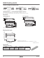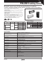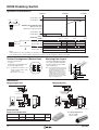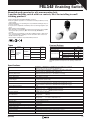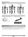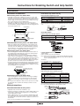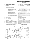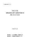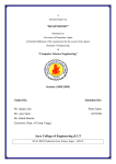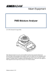
1
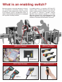
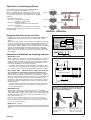
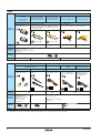
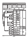
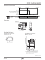
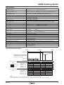
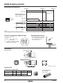
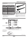
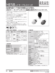
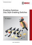
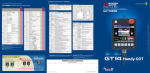
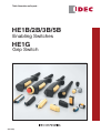
Think Automation and beyond...
HE1B/2B/3B/5B
Enabling Switches
HE1G
Grip Switch
(05/12/07)
AS-Interface Components
What is an enabling switch?
Because operators use teach pendants in hazardous environments performing teaching, system
changeover, and maintenance of robots, they must
have protection against unpredictable motion of
robots, and therefore teach pendants are equipped
with 3-position enabling switches.
An enabling switch is a 3-position (OFF-ON-OFF)
switch to allow a machine operation only when the
switch is lightly pressed and held in the mid position (position 2). Because it disables machine
operation when released (position 1) or further
depressed (position 3) by a panicked operator, the
safety of operators using teach pendants or grip
switches in hazardous environments is ensured.
HE1G Grip Switch
HG2S CC Pendant
Two HE1B Enabling
Switches inside
HE9Z-GSH51 Grip Switch Housing
+ HE5B Enabling Switch
HG1T Small Pendant
Held in
Left Hand
2
Held in
Right Hand
HE3B Enabling
Switch inside
(05/12/07)
Operation of enabling switches
The requirement for operation of 3-position enabling
switches (according to IEC 60204-1; 9.2.5.8):
When an enabling device is provided as a part of a system, it shall be designed to allow motion when actuated
in one position only. In any other position motion shall be
stopped.
– for a three-position type:
• position 1: off-function of the switch
(actuator is not operated)
• position 2: enabling function
(actuator is operated in its mid position)
• position 3: off-function
(actuator is operated past its mid position)
When returning from position 3 to position 2, the function
shall be ended.
Position 1
OFF
1. Press lightly
2. Release
Position 2
ON
4. Release
3. Press tightly
Position 3
OFF
Terminal Contact
Movable Contact
Disparity detection of two contacts
• A high level of safety—safety category 3 or higher (ISO 13849-1)—is
required when an operator works near a hazard inside a safety
guard.
When released to position 1, the contacts are opened (turned off) by
the force of a released spring. The 3-position enabling switches must
be prepared for failures such as contact welding and short-circuits,
and a dual circuit is provided. Even if one contact fails, the remaining
contact can disable machine operation. Furthermore, a disparity
detection circuit is provided so that machine operation is disabled
when a disparity between the two circuits is detected using a safety
relay module.
International standards on enabling switches
Disparity Detection Circuit
for Dual Contacts
Both ON
Machine can
operate (normal)
Both OFF
Machine cannot
operate (normal)
Agree
2-circuit
input
Disagree
One ON, the
other OFF
Machine cannot
operate (failure of
enabling switch,
machine cannot
restart)
Enabling
Device
• IEC 60204-1: 1997
9.2.4 Where it is necessary to suspend safeguarding, (e.g. for setting or maintenance purposes), a mode selection device or means
capable of being secured (e.g. locked) in the desired mode shall be
provided so as to prevent automatic operation. In addition, one or
more of the following means shall be provided:
- a portable control station (e.g. pendant) with an emergency stop
device and, where appropriate, an enabling device. Where a portable station is in use, motion may be initiated only from that station.
L (+)
24V DC
F1
A1
• ISO 12100-2: 2003 Control mode for setting, teaching, process changeover, fault-finding, cleaning or maintenance
4.11.9 Where, for setting, teaching, process changeover, fault-finding, cleaning or maintenance of machinery, a guard has to be displaced or removed and/or a protective device has to be disabled, and
where it is necessary for the purpose of these operations for the
machinery or part of the machinery to be put in operation, safety of
the operator shall be achieved using a specific control mode which
simultaneously:
- permits operation of the hazardous elements only by continuous
actuation of an enabling device, a hold-to-run control device or a
two-hand control device.
• ANSI/RIA R15.06
The pendant or teaching control device shall have an enabling
device using a three position switch which, when continuously held in
a detented position, permits motion. Release of or compression past
the midpoint detent of the device shall stop robot motion using circuitry consistent with 4.5.
ESC
External
Start Condition
S33
S34
13
23
33
14
24
34
HR1S-AF
Safety Relay Module
A2
S11
S12 S21
S22
Safety Output
S1
Enabling
Switch
N (—)
A method of changing an operation mode (auto/
manual) using the HS5B safety switch and grip
style enabling switch (HE1G)
Note: Tests have shown that human reaction to an emergency may be to
release an object, or hold on tighter, thus compressing an enabling device.
Design and installation of the enabling device should consider the ergonomics issues of sustained activation.
• ANSI B11.19, 12.3.1.3
Enabling devices shall be designed and constructed to permit limited
and supervised machine motion while personnel are inside a hazard
area.
(05/12/07)
Enabling switch is attached
to the safety switch—
machine operates automatically.
Enabling switch is
detached from the safety
switch—machine can be
operated only manually.
3
AS-Interface Components
Types
Enabling Switch
Side Mounting Type
(1-contact)
Top Mounting Type
(1-contact)
Rectangular Type
(6 contacts maximum)
(without rubber boot)
HE1B
Rectangular Type
16mm Round Hole Type 16mm Round Hole Type
(6 contacts maximum)
(without rubber boot)
(with rubber boot)
(with rubber boot)
HE2B
Small and ideal for installing in enabling devices.
Type and
Appearance
Monitor Switch
Degree of
Protection
Applicable
Standards
HE3B
Ideal for 4-finger operation.
A maximum of 6 contacts can be installed (2 contacts
each for 3-position switch, button return monitor and
button depress monitor)
Rectangular shape
Can be mounted easily in a ø16 mm round hole.
Monitor Switch
IP40
IP65
IP40
IP65
IEC / EN 60947-5-1 (DEMKO approval)
UL508 (UL recognized)
CSA C22. No. 14 (c-UL recognized)
JIS C8201-5-1
Standards
Page
6, 7
8 to 10
11, 12
Enabling Switch
Grip Switch
2-contact, ø16mm Round Hole,
With Rubber Boot
With Emergency Stop
Switch
HE5B
With Monitor Switch
HE9Z-GSH51 (Note)
Can be mounted easily on
ø16 mm round hole.
Compact grip switch
housing
With Momentary
Pushbutton Switch
HE1G
2-contact 3-position switch
and monitoring contact.
Combination of emergency stop switch and 3position enabling switch.
Combination of 3-position
enabling switch and
momentary pushbutton
switch (1NO/2NO).
Type and
Appearance
Degree of
Protection
Applicable
Standards
IP65
IEC / EN 60947-5-1
(DEMKO approval)
UL508 (UL recognized)
CSA C22. No. 14
(c-UL recognized)
JIS C8201-5-1
IP66
IEC / EN60529
UL50
IP65
IEC / EN 60947-5-1 (BG approval)
GS-ET-22 (BG approval)
UL508 (UL listed)
CSA C22. No. 14 (c-UL listed)
JIS C8201-5-1
Standards
Page
13, 14
15
16 to 18
Note: HE9Z-GSH51 is housing only. Install the HE5B enabling switch to use as a grip switch. See page 15 for details.
4
(05/12/07)
Selection Chart of Enabling Switch and Grip Switch
ISO 12100-2: 2003
Control mode for setting,
teaching, process changeover,
fault-finding, cleaning or maintenance
4.11.9
permits operation of the hazardous elements only by continuous actuation of an
enabling device, a hold-to-run
control device or a two-hand
control device;
IEC 60204-1: 1997
9.2.5.8
When an enabling device
is provided as a part of a
system, it shall be
designed to allow motion
when actuated in one
position only. In any other
position motion shall be
stopped.
ANSI/ RIA R15.06
4.7.3 Enabling device
The pendant or teaching
control device shall have
an enabling device using
a three position switch,
which continuously held in
a detented position, permits motion.
ANSI B11.19
12.3.1.1 Enabling devices
shall be designed and
constructed to permit limited and supervised
machine motion while
personnel are inside a
hazard area.
For Installation in Equipment
Style
3-position
Switch with
1 Contact
(2 switches
are used for
duplication)
SEMI S2-0703
20.4 Industrial robots and
industrial robot systems
should meet the requirements of appropriate
national or international
standards, e.g., ANSI/RIA
R15.06, ISO standards
10218, EN 775.
Standards
Marks
HE1B-M1N
Panel Top Installation
IP40
Panel Side Installation
IP40
HE1B-M1
HE2B-M200
IP40
w/o Monitor
Switch
for Position
Detection
HE2B-M200P∗
IP65
3-position
Switch with
2 Contacts
Installed in Rectangular
Panel Cut-out
(4-finger operation)
HE2B-M211
HE2B-M222
IP40
w/Monitor
Switch
for Position
Detection
IEC/EN60947-5-1
UL508
CSA C22.2 No.14
HE2B-M211P∗
HE2B-M222P∗
IP65
HE3B-M2
For Direct Operation with Hand
IP40
Installed in ø16mm
Round Hole (thumb or
3-finger operation)
HE3B-M2P∗
IP65
Installed in ø16mm
Round Hole (thumb
operation)
HE5B-M2P∗
IP65
HE9Z-GSH51 + HE5B-M2P∗
w/o Monitor
Switch
for Position
Detection
IP65
w/Monitor
Switch
for Position
Detection
IP66
(HE9Z-GSH51)
IEC/EN60529
UL50
(HE5B-M2P∗)
IEC/EN60947-5-1
UL508
CSA C22.2 No.14
HE1G-21SM
Grip Switch Type
HE1G-20ME
w/Pushbutton Switch
for Emergency Stop
IEC/EN60947-5-1
UL508
CSA C22.2 No.14
GS-ET-22
IP65
HE1G-2∗MB
w/Momentary Action
Pushbutton
Switch
(05/12/07)
IP65
5
HE1B Enabling Switch
3-position enabling switch to avoid hazards.
Ideal for installing in teach pendants and other enabling devices.
• Ergonomically-designed OFF-ON-OFF.
• Direct opening action mechanism for shifting from position 2 (ON)
to position 3 (OFF) (EN 60947-5-1/IEC 60947-5-1, Annex K).
• The switch does not turn ON while being released from position 3
(OFF when pressed) to position 1 (OFF when released)
(IEC60204-1, 9.2.5.8).
• Reliable performance in compact and lightweight package.
Direct Opening
Action
Types
Mounting Style
Side Mounting
Top Mounting
Contact Configuration
1 contact (3-position)
Type No.
HE1B-M1
HE1B-M1N
Ordering Type No.
HE1B-M1PN10
HE1B-M1NPN10
Package Quantity
10
• Minimum applicable load (reference value): 3V AC/DC, 5 mA
Ratings
• Contact Ratings
Rated Insulation Voltage (Ui)
250V
Rated Thermal Current (Ith)
5A
Rated Voltage (Ue)
AC 50/60 Hz
Rated Current (Ie)
DC
30V
125V
Resistive Load (AC-12)
—
3A
1.5A
Inductive Load (AC-15)
—
1.5A
0.75A
Resistive Load (DC-12)
2A
0.4A
0.2A
Inductive Load (DC-13)
1A
0.22A
0.1A
Contact Configuration (3-position switch)
250V
1 contact
• Minimum applicable load (reference value): 3V AC/DC, 5 mA
Specifications
Applicable Standards
IEC 60947-5-1, EN 60947-5-1 (DEMKO approval)
UL508 (UL recognized), CSA C22.2, No. 14 (c-UL recognized), JIS C8201-5-1
Applicable Standards for Use
ISO 12100 / EN 292, IEC 60204-1 / EN 60204-1
ISO 11161 / prEN 11161, ISO 10218 / EN 775, ANSI/RIA R15.06, ANSI B11.19
Operating Temperature
–25 to +60°C (no freezing)
Relative Humidity
45 to 85% (no condensation)
Storage Temperature
–40 to +80°C (no freezing)
Pollution Degree
2
Contact Resistance
50 mΩ maximum (initial value)
Insulation Resistance
100 MΩ minimum
Impulse Withstand Voltage
2.5 kV
Operating Frequency
1,200 operations per hour
Mechanical Durability
Position 1 → 2 → 1:
1,000,000 operations
Position 1 → 2 → 3 → 1: 100,000 operations
Electrical Durability
100,000 operations minimum
Shock Resistance
Operating extremes: 150 m/s2
Damage limits:
1,000 m/s2
Vibration Resistance
Operating extremes: 5 to 55 Hz, amplitude 0.5 mm
Damage limits:
16.7 Hz, amplitude 1.5 mm
Terminal Style
Solder terminal
Applicable Wire
1 cable, 0.5 mm2 maximum
Solder Terminal Heat Resistance
310 to 350°C, 3 seconds maximum
Terminal Tensile Strength
20N minimum
Mounting Screw Recommended Tightening Torque
HE1B-M1: M3 screw / 0.5 to 0.8 N·m
HE1B-M1N: M2.6 screw / 0.4 to 0.6 N·m
Degree of Protection
IP40, except terminals
Conditional Short-circuit Current
50A (250V) (Use 250V/10A fast acting type fuse for short-circuit protection.)
Direct Opening Force
30N minimum (position 2 → 3)
Operator Strength
250N minimum
Weight (approx.)
6g
6
(05/12/07)
HE1B Enabling Switch
Operation Characteristics
Position 1
Position 2
Position 3
Approx. 15N
Operating Force (Reference Value)
(When pressing the center of operator)
Approx. 3N
1.4±0.3
Travel (mm) 0
: ON (Closed)
: OFF (Open)
Pressing (
)
Releasing (
)
2.2±0.3
2.7±0.5
5.0
Dimensions
30
13.6
12
7.6
4
4
13
5
7
When pressed to
position 3: 2
2.8
24
4
8
Solder Terminal
Mounting Hole Layout
ø2
.8
24±0.2
Mounting Panel
Thickness
24±0.5
15 min.
9 min.
3
M
• HE1B-M1N (top mounting type)
Mounting screw: M2.6
Mounting Screw Length:
Mounting panel thickness + 5 to 6
• HE1B-M1 (side mounting type)
Mounting screw: M3
Insert the nuts supplied with the switch.
Note: When installed on a mounting panel thicker than 2
mm, the actuator surface is below the panel when
the button is pressed to position 3.
All dimensions in mm.
(05/12/07)
7
HE2B Enabling Switch
Multi-contact 3-position enabling switches Ideal for installing in large teach pendants
• Ergonomically-designed OFF-ON-OFF operation.
• Easy recognition of position 1 to 2 transition is made possible by a snap
action switch.
• Sufficient difference in operating force is provided for shifting from position 2 to 3.
• Low pressure is required to maintain position 2, allowing for longtime
operation.
• Reliable operation is assured even when the edge of the operator button
is pressed.
• The switch does not turn ON while being released from position 3 (OFF)
to position 1 (OFF) (IEC60204-1, 9.2.5.8).
• Some teach pendants are equipped with two 3-position enabling
switches, and when one switch is pressed to position 3 (OFF), the other
switch must not enable machine operation even when pressed to position 2. Enabling of machine operation must resume after both switches
are released. For this purpose, also available are 3-position enabling
switches with monitoring switches for button returned to position 1 and
button pressed to position 3 (monitor switches have direct opening
action mechanism).
• Two contacts are provided in a 3-position enabling switch so that even if
one contact fails due to welding or short-circuit, the other contact can
disable machine operation.
• The waterproof rubber boot provides IP65 protection.
Direct Opening
Action
Types
Type
3-position Switch
Without Rubber Boot
Rubber Boot Material:
Silicon Rubber
Color:
Y: yellow
B: black
With
Rubber Boot
Rubber Boot Material:
NBR/PVC Polyblend
Color: gray
Contact Configuration
Button Return
Button Depress
Monitor Switch
Monitor Switch
Type No.
2
0
0
HE2B-M200
2
1
1
HE2B-M211
2
2
2
HE2B-M222
2
0
0
HE2B-M200P∗
2
1
1
HE2B-M211P∗
2
2
2
HE2B-M222P∗
2
0
0
HE2B-M200PN1
2
1
1
HE2B-M211PN1
2
2
2
HE2B-M222PN1
Ordering Type No.
Package
Quantity
HE2B-M200
HE2B-M200PN10
HE2B-M211
HE2B-M211PN10
HE2B-M222
HE2B-M222PN10
HE2B-M200P∗
HE2B-M200P∗PN10
HE2B-M211P∗
HE2B-M211P∗PN10
HE2B-M222P∗
HE2B-M222P∗PN10
HE2B-M200PN1
HE2B-M200PN1PN10
HE2B-M211PN1
HE2B-M211PN1PN10
HE2B-M222PN1
HE2B-M222PN1PN10
1
10
1
10
1
10
1
10
1
10
1
10
1
10
1
10
1
10
Note: Specify rubber boot color code in place of ∗ in the Type No.
• Type No. Development
HE2B - M 2 0 0 P ∗
• 3-position Switch
2: 2 contacts
• Button Return Monitor Switch
0: No switch
1: 1 contact
2: 2 contacts
• Button Depress Monitor Switch
0: No switch
1: 1 contact
2: 2 contacts
• Rubber Boot Material, Color
Blank: No rubber boot
Y:
Silicon rubber, yellow
B:
Silicon rubber, black
N1: NBR/PVC polyblend, gray
• Rubber Boot
Blank: No rubber boot
P:
With rubber boot
Ratings
• Contact Ratings
Rated Insulation Voltage (Ui)
Rated Thermal Current (Ith)
Rated Voltage (Ue)
Resistive Load (AC-12)
Inductive Load (AC-15)
Resistive Load (DC-12)
DC
Inductive Load (DC-13)
Resistive Load (AC-12)
AC
Inductive Load (AC-15)
Resistive Load (DC-12)
DC
Inductive Load (DC-13)
3-position Switch
Button Return Monitor Switch
Button Depress Monitor Switch
AC
3-position Switch
Rated Current (Ie)
Button Return Monitor Switch
Button Depress Monitor Switch
Contact Configuration
30V
—
—
1A
0.7A
—
—
2A
1A
250V
3A
125V
1A
0.7A
0.2A
0.1A
2A
1A
0.4A
0.22A
2 contacts
0 to 2 contacts
0 to 2 contacts
250V
0.5A
0.5A
—
—
1A
0.5A
0.2A
0.1A
• Minimum applicable load (reference value): 3V AC/DC, 5 mA
8
(05/12/07)
HE2B Enabling Switch
Specifications
IEC 60947-5-1, EN60947-5-1 (DEMKO approval), UL508 (UL recognized)
CSA C22.2, No. 14 (c-UL recognized), JIS C8201-5-1
ISO 12100 / EN 292, IEC 60204-1 / EN 60204-1
ISO11161 / prEN 11161, ISO10218 / EN 775, ANSI / RIA R15.06, ANSI B11.19
–25 to +60°C (no freezing) (without rubber boot, with silicon rubber boot)
–10 to +60°C (no freezing) (with NBR/PVC polyblend rubber boot)
45 to 85% RH (no condensation)
–40 to +80°C (no freezing)
2 (inside panel, terminal side)
3 (outside panel, operator side)
50 mΩ maximum (initial value)
Between live and dead metal parts: 100 MΩ minimum (500V DC megger)
Between terminals of different poles: 100 MΩ minimum (500V DC megger)
2.5 kV
1,200 operations per hour
Position 1 → 2 → 1:
1,000,000 operations minimum
Position 1 → 2 → 3 → 1: 100,000 operations minimum
100,000 operations minimum
Operating extremes: 150 m/s2
Damage limits:
1,000 m/s2
Applicable Standards
Applicable Standards for Use
Operating Temperature
Relative Humidity
Storage Temperature
Pollution Degree
Contact Resistance
Insulation Resistance
Impulse Withstand Voltage
Operating Frequency
Mechanical Durability
Electrical Durability
Shock Resistance
Vibration Resistance
Terminal Style
Applicable Wire
Solder Terminal Heat Resistance
Terminal Tensile Strength
Mounting Screw Recommended Tightening Torque
Degree of Protection
Conditional Short-circuit Current
Direct Opening Force
Operator Strength
Weight (approx.)
Operating extremes: 5 to 55 Hz, amplitude 0.5 mm
Damage limits:
16.7 Hz, amplitude 1.5 mm
Solder terminal
1 cable, 0.5 mm2 maximum
310 to 350 °C, 3 seconds maximum
20N minimum
0.5 to 0.8 N·m
IP40 (without rubber boot)
IP65 (with rubber boot)
50A (250V) (Use 250V/10A fast acting type fuse for short-circuit protection.)
60N minimum (button return monitor and button depress monitor switches)
500N minimum (when pressing the entire button surface)
26g (without rubber boot)
30g (with rubber boot)
Operation Characteristics
Position 1
Position 2
Position 3
Approx. 30N
Operating Force (reference value)
(without rubber boot, when pressing
the center of the operator)
Approx. 4N
Travel (mm) 0
When pressing the operator
: ON (closed)
: OFF (open)
1.4±0.3
2.4±0.3 3.0±0.3 3.6±0.5 4.2±0.5
6.0±0.5
Between NO1 - C1
Between NO2 - C2
Between 11 - 12
Between 21 - 22
Between 31 - 32
Between 41 - 42
When releasing the operator Between NO1 - C1
Between NO2 - C2
Between 11 - 12
Between 21 - 22
Between 31 - 32
Between 41 - 42
Notes:
• When a rubber boot is used, the operating force depends on the operating temperature.
• The operating force to shift the switch from position 2 to position 3 can be changed. For details, contact IDEC.
(05/12/07)
9
AS-Interface Components
HE2B Enabling Switch
Terminal Arrangement (Bottom View)
IDEC Logo Side
IDEC Logo Side
IDEC Logo Side
HE2B-M200
HE2B-M211
HE2B-M222
• 3-position switch (note):
2 contacts, terminal nos. between NO1 – C1, NO2 – C2
• Button return monitor switch: 0 to 2 contacts, terminal nos. between 11 – 12, 21 – 22
• Button depress monitor switch: 0 to 2 contacts, terminal nos. between 31 – 32, 41 – 42
Note: Use NO and C terminals for OFF → ON → OFF 3-position switch (NC terminal is not used).
Dimensions
• Without Rubber Boot
• With Rubber Boot
16
10
19
11.5
M3 nut hole
14.2 14.8
7
14.2
5
13.5
5.5
87
78
66.5
6.5
90
68
5
69
7
69
• M3 nuts are supplied with the HE2B enabling switch.
2 -ø
3.2
+0.2
0
70
12.2
Mounting Panel Thickness: 6 max.
Mounting Hole Layout
78
±0.2
±0.2
• Mounting screw: Two M3 screws
• Length of mounting screw: The thickness of mounting panel + 4 to 5 mm
Mounting Screws
All dimensions in mm.
Accessories
• Replacement Rubber Boot
Material
Color
Type No.
Ordering Type No.
Silicon Rubber
Y: yellow
B: black
HE9Z-D2∗
HE9Z-D2∗PN10
NBR/PVC Polyblend
Gray
HE9Z-D2N1
HE9Z-D2N1PN10
Package Quantity
10
Note: Specify a rubber boot color code in place of ∗ in the Type No.
10
(05/12/07)
HE3B Enabling Switch
Rectangular operator part with ø16 mm mounting for easy installation.
2-contact 3-position enabling switches ideal for installing in small teach pendants.
• Ergonomically-designed OFF-ON-OFF operation.
• Easy recognition of position 1 to 2 transition is made possible by a
snap action switch.
• Sufficient difference in operating force is provided for shifting from
position 2 to position 3.
• Low pressure is required to maintain in position 2 allowing for
longtime operation.
• Reliable operation is assured even when the edge of the operator
button is pressed.
• The switch does not turn ON while being released from position 3
(OFF) to position 1 (OFF) (IEC60204-1, 9.2.5.8).
• Two contacts are provided in a 3-position enabling switch so that
even one contact fails due to welding or short-circuit, the other
contact can disable machine operation.
• The waterproof rubber boot provides IP65 protection.
Types
Type
Contact Ratings
Contact
Configuration
With Rubber Boot
Without Rubber Boot
Rubber Boot Material:
Silicon Rubber
Color:
Y: yellow, B: black
Type No.
HE3B-M2
2 contacts
(3-position
switch)
Rubber Boot Material:
NBR/PVC Polyblend
Color: gray
Package
Ordering Type No.
Quantity
HE3B-M2
1
HE3B-M2PN10
10
HE3B-M2P∗
1
HE3B-M2P∗PN10
10
HE3B-M2PN1
1
HE3B-M2PN1PN10
10
HE3B-M2P∗
HE3B-M2PN1
Rated Insulation Voltage (Ui)
Rated Thermal Current (Ith)
Rated Voltage (Ue)
Resistive Load (AC-12)
AC
Inductive Load (AC-15)
Rated Current
(Ie)
Resistive Load (DC-12)
DC
Inductive Load (DC-13)
Contact Configuration (3-position switch)
125V
3A
30V
125V
—
1A
—
0.7A
1A
0.2A
0.7A
0.1A
2 contacts
Minimum applicable load (reference value): 3V AC/DC, 5 mA
Note: Specify rubber boot color code in place of ∗ in the Type No.
Specifications
Applicable Standards
IEC 60947-5-1, EN 60947-5-1 (DEMKO approval)
UL508 (UL recognized), CSA C22.2, No. 14 (c-UL recognized), JIS C8201-5-1
Applicable Standards for Use
ISO 12100 / EN 292, IEC 60204-1 / EN 60204-1
ISO 11161 / prEN 11161, ISO 10218 / EN 775
ANSI/RIA R15.06, ANSI B11.19
Operating Temperature
–25 to +60°C (no freezing) (without rubber boot, with silicon rubber boot)
–10 to +60°C (no freezing) (with NBR/PVC polyblend rubber boot)
Relative Humidity
45 to 85% (no condensation)
Storage Temperature
–40 to +80°C (no freezing)
Pollution Degree
2 (inside panel, terminal side)
3 (outside panel, operator side)
Contact Resistance
50 mΩ maximum (initial value)
Insulation Resistance
Between live and dead metal parts: 100 MΩ minimum (500V DC megger)
Between terminals of different poles: 100 MΩ minimum (500V DC megger)
Impulse Withstand Voltage
1.5 kV
Operating Frequency
1,200 operations per hour
Mechanical Durability
Position 1 → 2 → 1:
1,000,000 operations minimum
Position 1 → 2 → 3 → 1: 100,000 operations minimum
Electrical Durability
100,000 operations minimum
Shock Resistance
Operating extremes: 150 m/s2
Damage limits:
500 m/s2
Vibration Resistance
Operating extremes: 5 to 55 Hz, amplitude 0.5 mm
Damage limits:
16.7 Hz, amplitude 1.5 mm
Terminal Style
Solder terminal
Applicable Wire
1 cable, 0.5 mm2 maximum
Solder Terminal Heat Resistance
310 to 350°C, 3 seconds maximum
Terminal Tensile Strength
20N minimum
Locking Ring Recommended Tightening Torque
0.68 to 0.88 N·m
Degree of Protection
IP40 (without rubber boot)
IP65 (with rubber boot)
Conditional Short-circuit Current
50A (250V) (Use 250V/10A fast acting type fuse for short-circuit protection.)
Operator Strength
500N minimum (pressing the entire operator surface)
Weight (approx.)
14g (without rubber boot)
18g (with rubber boot)
(05/12/07)
11
AS-Interface Components
HE3B Enabling Switch
Operation Characteristics
Position 1
Position 2
Position 3
Part A: Approx. 56N
Part B
Part B: Approx. 14N
Part A
Operating Force (reference value)
(Without rubber boot)
(When part A or part B is pressed)
Part A: Approx. 10N
Part B: Approx. 2N
Part A 0
0.8 –0.2
+0.7
1.0 –0.2
+0.7
1.7 –0.2
+0.7
1.9 –0.2
Part B 0
When pressing the operator
Between NO1 – C1
: ON (closed)
Between NO2 – C2
: OFF (open)
+0.7
–0.3
+0.7
–0.3
+0.7
–0.3
+0.4
–0.3
Travel (mm)
2.3
3.0
4.2
+0.7
5.0
When releasing the operator
Between NO1 – C1
Between NO2 – C2
Notes:
• When rubber boot is used, operating force depends on the operating temperature.
• The operating force to shift the switch from position 2 to position 3 can be changed. For details, contact IDEC.
Terminal Arrangement (Bottom View)
Mounting Hole Layout
• 3-position switch (Note)
2 contacts
• Recommended tightening torque
for locking ring: 0.68 to 0.88 N·m
• Use the locking ring wrench MT001 for tightening.
Note: Use NO and C terminals for the
3-position switch of OFF → ON
→ OFF operation
(NC terminal is not used).
NC2
NO1
NO2
C1
C2
Mounting Panel
Thickness 0.5 to 4
Terminal No.: between NO1 and
C1, between NO2 and C2
NC1
e)
.2
+0 0
6.2
Note: To maintain waterproof property
of the switch, do not drill through
the anti-rotation hole in the
mounting panel. When not providing a hole, cut off the antirotation projection from the rubber boot. When cutting off the
projection, ensure not to make a
hole in the rubber boot.
ø1
.2
+0 0
ot
(N
.5
2 g
.2
ø3 pth: ionin
le)
Ho
De osit
(P
30
Anti-rotation Ring
Locking Ring
Dimensions
• Without Rubber Boot
• With Rubber Boot
Mounting Panel Thickness: 0.5 to 4
Locking Ring
Locking Ring
3
3
2.5
2.5
Mounting Panel Thickness: 0.5 to 4
Anti-rotation Ring
Rubber Boot
Anti-rotation Ring
14.5
12.3
8.5
22.2
NBR/PVC Polyblend
39.5
(54)
14.5
25.5
(34.5)
27.5
11.5
(39)
9
13.1
R2
16
8
15
20.5
All dimensions in mm.
• Replacement Rubber Boot
Silicon Rubber
Solder Terminal
Width 2.8 × 0.5t
55
30
38.1
(51.2)
24.6
(33.1)
8.5
5 5
R1
15
Accessories
Material
25
R1
Solder Terminal
Width 2.8 × 0.5t
8
15.5
13
9.5
2
ø3
Color
Type No.
Ordering Type No.
Y: yellow
B: black
Gray
HE9Z-D3∗
HE9Z-D3∗PN10
HE9Z-D3N1
HE9Z-D3N1PN10
Package
Quantity
• Locking Ring Wrench
Type No: MT-001
Material: Metal
10
• Specify rubber boot color code in place of ∗ in the Type No.
12
(05/12/07)
HE5B Enabling Switch
Round-shaped operator for ø16 mm mounting hole.
3-position enabling switch with two contacts, ideal for installing in small
teaching pendants.
• Ergonomically-designed OFF-ON-OFF operation.
• Easy recognition of position 1 to 2 transition is made possible by a snap
action switch.
• Sufficient difference in operating force is provided for shifting from position 2 to position 3.
• Low pressure is required to maintain position 2, allowing longtime operation.
• Grip switch housing available.
• The switch does not turn ON when being released from position 3 (OFF
when pressed) to position 1 (OFF when released) (IEC60204-1,
9.2.5.8).
• Two contacts are provided in a 3-position enabling switch so that even if
one contact fails due to welding or short-circuit, the other contact can
disable machine operation.
• The waterproof rubber boot provides IP65 protection.
Types
With Rubber Boot
Type
Silicon
Rubber
Y: yellow
B: black
Contact Ratings
Contact
Configuration
Type No.
Ordering Type No.
HE5B-M2P∗
Package
Quantity
1
Rated Insulation Voltage (Ui)
3A
Rated Voltage (Ue)
HE5B-M2P∗
2 contacts
(3-position
switch)
NBR/PVC
HE5B-M2P∗PN10
10
HE5B-M2PN1
1
AC
Rated Current (Ie)
HE5B-M2PN1
HE5B-M2PN1PN10
• Specify rubber boot color code in place of ∗ in the Type No.
10
125V
Rated Current (Ith)
DC
30V
125V
Resistive Load (AC-12)
–
0.5A
Inductive Load (AC-15)
–
0.3A
Resistive Load (DC-12)
1A
–
Inductive Load (DC-13)
0.7A
–
Contact Configuration (3-position switch)
2 contacts
Minimum applicable load (reference): 3V AC/DC, 5mA
Applicable operation area depends on the operating conditions and
load.
Specifications
Applicable Standards
Applicable Standards for Use
Operating Temperature
Relative Humidity
Storage Temperature
Pollution Degree
Contact Resistance
Insulation Resistance
Impulse Withstand Voltage
Operating Frequency
Mechanical Durability
Electrical Durability
Shock Resistance
Vibration Resistance
Terminal Style
Applicable Wire
Solder Terminal Heat Resistance
Terminal Tensile Strength
Locking Ring Recommended Tightening Torque
Degree of Protection
Conditional Short-circuit Current
Operator Strength
Weight (approx.)
(05/12/07)
IEC 60947-5-1, EN 60947-5-1 (DEMKO approval),UL508 (UL recognized),
CSA C22.2, No. 14 (c-UL recognized), JIS C8201-5-1
ISO 12100 / EN292, IEC 60204-1 / EN 60204-1, ISO 11161 / prEN 11161,
ISO 10218 / EN 775, ANSI/RIA R15.06, ANSI B11.19
Silicon rubber boot:
–25 to 60°C (no freezing)
NBR/PVC Polyblend rubber boot: –10 to 60°C (no freezing)
45 to 85% (no condensation)
–40 to +80°C (no freezing)
2 (inside panel, terminal side)
3 (outside panel, operator side)
50 mΩ maximum (initial value)
Between live and dead metal parts: 100 MΩ minimum (500V DC megger)
Between terminals of different pole: 100 MΩ minimum (500V DC megger)
1.5 kV
1,200 operations per hour
Position 1 ➝ 2 ➝ 1:
1,000,000 operations minimum
Position 1 ➝ 2 ➝ 3 ➝ 1: 100,000 operations minimum
100,000 operations minimum
Operating extremes: 150 m/s2
Damage limits:
500 m/s2
Operating extremes: 5 to 55 Hz, amplitude 0.5 mm
Damage limits:
5 to 55 Hz, amplitude 0.5 mm
Solder terminal
0.5 mm2 maximum per line
310 to 350°C, 3 seconds maximum
20 N minimum
0.29 to 0.49 N·m
IP65
50A (125V) (Use 250V/10A fast acting type fuse for short circuit protection.)
250N minimum (when pressing the entire operator surface)
9g
13
AS-Interface Components
HE5B Enabling Switch
Operating Characteristics
Position 1
Position 2
Position 3
Approx. 12N
Reference Operating Load
(when pressing the center
of the the operator)
: ON (Close)
Approx. 3N
: OFF (Open)
Travel (mm) 0
Pressing Button
2.3
±0.3
3.0
±0.3
3.6
±0.5
5.0
±0.5
NO1-C1
NO2-C2
Releasing Button
NO1-C1
NO2-C2
Terminal Arrangement (Bottom View)
Mounting Hole Layout
• 3-position switch (Note)
2 contacts
Terminal No.: between NO1 and C1,
NO2 and C2
Note: For OFF ➝ ON ➝ OFF 3-position
switches, use NO and C terminals
(NC terminal is not used).
• Recommended Tightening Torque
for Locking Ring: 0.29 to 0.49 N·m
• Use the MT-001 locking ring
wrench for tightening.
Panel Thickness 0.5 to 4
Notes:
• Operating force depends on ambient temperature.
• The operating force to shift the switch from position 2 to position 3 can be changed. For details, consult IDEC.
6.
ø1
.2
+0 0
0
Anti-rotation Ring
Locking Ring
Dimensions
Panel Thickness 0.5 to 4
With Rubber Boot
3
2.5
Locking Ring
Anti-rotation Ring
Rubber Boot
5
5
ø20
Solder Terminal Width 2.8 × 0.5t
8
15
16
All dimensions in mm.
Accessories
• Replacement Rubber Boot
Rubber Boot Material
Color
Type No.
Ordering
Type No.
Silicon Rubber
B: black
Y: yellow
HE9Z-D5∗
NBR/PVC Polyblend
Gray
HE9Z-D5N1 HE9Z-D5N1PN10
HE9Z-D5∗PN10
Package
Quantity
• Locking Ring Wrench
Type No: MT-001
Material: Metal
10
• Specify rubber boot color code in place of ∗ in the Type No.
14
(05/12/07)
HE5B Enabling Switch
• Grip Switch Housing
HE5B enabling switches can be installed in the HE9Z-GSH51
grip switch housing to be used as 3-position grip switches.
Types
Type No.
HE9Z-GSH51
Ordering Type No.
Package Quantity
HE9Z-GSH51
1
Specifications
IEC / EN 60529
UL50
Applicable Standards
Operating Temperature
–25 to 60°C (no freezing)
Relative Humidity
45 to 85% RH (no condensation)
Storage Temperature
–40 to 80°C (no freezing)
Pollution Degree
3
Shock Resistance
Damage limits: 500 m/s2
Vibration Resistance
Damage limits: 5 to 55 Hz, amplitude 0.5 mm
Electric Shock Protection Class
Class II (when using HE5B-M2P∗)
Applicable Cable
Outside diameter ø4.5 to 10 mm
Conduit Size
M16 (connector is supplied with the grip switch
housing)
Degree of Protection
IP65 (with HE5B-M2P∗)
NEMA type 4X indoor use only
(with HE5B-M2P∗)
Weight (approx.)
65g (grip switch housing only)
Double Insulation
Notes:
• The HE9Z-GSH51 grip switch housing does not include the
HE5B enabling switch. The enabling switch must be ordered
separately.
• The HE5B enabling switch must be installed and wired to
the HE9Z-GSH51 grip switch housing by the user. For information on wiring, see the instruction sheet supplied with the
HE9Z-GSH51.
• The above specifications are for the grip switch housing only.
For enabling switch, see the HE5B specifications on page 13.
• The following switches can be installed on the grip switch housing to
be used as hand-held switches.
• AB6M pushbuttons (IP65, except for AB6M-V)
• AS6M selector switches (IP65)
• AS6M key selector switches (IP65)
Dimensions
HE9Z-GSH51
HE5B Enabling Switch
(78)
144
39
92
38
Connector
Type: SKINTOP BS-M16 × 1.5 (LAPP)
HE9Z-GSH51 + HE5B Construction
Housing
Head
Connector
Locking Ring
HE5B Enabling Switch (not supplied with the grip switch housing)
• Anti-rotation ring is not required when installing the HE5B enabling switch on the HE9Z-GSH51 grip switch housing.
Use the locking ring only.
• Mounting Bracket
50
Type No: HE9Z-GH1
20
M5 Holes
(2-ø5.3)
Plastic Coating
33
81
(05/12/07)
86
Material: SUS304
Thickness: t = 3.0 mm
All dimensions in mm.
15
HE1G Grip Switch
Ergonomically designed grip switch with two 3-position enabling switches.
• Ergonomically-designed OFF-ON-OFF operation.
• Direct opening action mechanism for shifting from position 2
(ON) to position 3 (OFF) (EN 60977-5-1/IEC 60947-5-1,
Annex K).
• The switch does not turn ON when being released from position 3 (OFF when pressed) to position 1 (OFF when released)
(IEC60204-1, 9.2.5.8).
• Two contacts are provided so that even if one contact fails due
to welding or short-circuit, the other contact can disable
machine operation.
• Emergency stop switch and momentary pushbutton versions
are available.
• Conduit connector supplied.
• HE1G-21SM is IP66 waterproof.
• Can be used for applications required by the ANSI robot standard.
BG standard in Germany
Direct Opening Double
Action
Insulation
Types
Contact Configuration
3-position Switch
Monitor Switch
Rubber Boot
Pushbutton
Ordering Type No.
Silicon Rubber / yellow
Without
With (1NC)
Momentary Pushbutton (1NO)
2 contacts
Emergency Stop Switch (2NC)
Without
Momentary Pushbutton (2NO)
Package
Quantity
HE1G-21SM
NBR / PVC Polyblend / gray
HE1G-21SM-1N
Silicon Rubber / yellow
HE1G-21SMB
NBR / PVC Polyblend / gray
HE1G-21SMB-1N
Silicon Rubber / yellow
HE1G-20ME
NBR / PVC Polyblend / gray
HE1G-20ME-1N
Silicon Rubber / yellow
HE1G-20MB
NBR / PVC Polyblend / gray
HE1G-20MB-1N
1
Ratings
• Contact Ratings
Rated Insulation Voltage (Ui)
250V (momentary pushbutton switch: 125V)
Rated Thermal Current (Ith)
3A
Rated Voltage (Ue)
3-position Switch
(terminal No. 1-2, 3-4)
Monitor Switch
(HE1G-21SM, terminal No. 5-6)
AC
DC
AC
DC
Rated Current (Ie)
Emergency Stop Switch
(HE1G-20ME, terminal No. 5-6, 7-8)
Momentary Pushbutton Switch
(HE1G-20MB, terminal No. 5-6, 7-8)
Contact Configuration
AC
DC
AC
DC
30V
125V
Resistive Load (AC-12)
—
3A
1.5A
Inductive Load (AC-15)
—
1.5A
0.75A
Resistive Load (DC-12)
2A
0.4A
0.2A
Inductive Load (DC-13)
1A
0.22A
0.1A
Resistive Load (AC-12)
—
2A
1A
Inductive Load (AC-15)
—
1A
0.5A
Resistive Load (DC-12)
2A
0.4A
0.2A
Inductive Load (DC-13)
1A
0.22A
0.1A
Resistive Load (AC-12)
—
—
—
Inductive Load (AC-15)
—
—
0.5A
Resistive Load (DC-12)
—
—
—
Inductive Load (DC-13)
—
—
0.1A
Resistive Load (AC-12)
—
0.5A
—
Inductive Load (AC-15)
—
0.3A
—
Resistive Load (DC-12)
1A
0.2A
—
0.7A
0.1A
—
Inductive Load (DC-13)
3-position Switch
2 contacts
Monitor Switch
0 or 1 contact
Emergency Stop Switch
0 or 2 contacts
Momentary Pushbutton Switch
0 to 2 contacts
250V
• Minimum applicable load (reference value): 3V AC/DC, 5 mA
• Applicable operation area depends on the operating conditions and load.
16
(05/12/07)
HE1G Grip Switch
Specifications
Applicable Standards
IEC 60947-5-1, EN 60947-5-1 (BG approval), GS-ET-22 (BG approval),
UL508 (UL listed), CSA C22.2, No. 14 (c-UL listed), JIS C8201-5-1
Applicable Standards for Use
ISO 12100 / EN 292, IEC 60204-1 / EN 60204-1, ISO11161 / prEN11161,
ISO 10218 / EN 775, ANSI/RIA R15.06, ANSI B11.19
Operating Temperature
Silicon rubber boot:
–25 to 60°C (no freezing)
NBR/PVC Polyblend rubber boot: –10 to 60°C (no freezing)
Relative Humidity
45 to 85% (no condensation)
Storage Temperature
–40 to +80°C (no freezing)
Pollution Degree
3
Contact Resistance
100 mΩ maximum (initial value)
Insulation Resistance
Between live and dead metal parts: 100 MΩ minimum (500V DC megger)
Between terminals of different pole: 100 MΩ minimum (500V DC megger)
Impulse Withstand Voltage
2.5 kV (except for momentary pushbuttons)
Electric Shock Protection Class
Class II (IEC 61140)
Operating Frequency
1,200 operations per hour
Mechanical Durability
Position 1 ➝ 2 ➝ 1:
1,000,000 operations minimum
Position 1 ➝ 2 ➝ 3 ➝ 1: 100,000 operations minimum
Electrical Durability
100,000 operations minimum
Shock Resistance
Operating extremes: 150 m/s2
Damage limits:
1,000 m/s2
Vibration Resistance
Operating extremes: 5 to 55 Hz, amplitude 0.5 mm minimum
Damage limits:
16.7 Hz, amplitude 1.5 mm minimum
Applicable Wire
0.14 to 1.5 mm2
Applicable Cable
Outside diameter ø7 to 13 mm
Conduit Size
M20 (connector is supplied with the grip switch)
Terminal Tensile Strength
20N minimum
Terminal Screw Tightening Torque
0.5 to 0.6 N·m
Degree of Protection
HE1G-21SM:
HE1G-20ME:
HE1G-20MB:
HE1G-21SMB:
IP66 (IEC 60529)
IP65 (IEC 60529)
IP65 (IEC 60529)
IP65 (IEC 60529)
Conditional Short-circuit Current
50A (250V) (Use 250V/10A fast acting type fuse for short circuit protection.)
Weight (approx.)
HE1G-21SM: 210g
HE1G-20ME: 250g
HE1G-20MB: 220g
Operating Characteristics
• HE1G-21SM
Position 1
Position 2
Position 3
• HE1G-20ME
Terminal No.
Pressing
Pressing
1–2
5–6
Releasing
1–2
1–2
3–4
+
Emergency Stop Switch: 2NC contact (terminal No. 5-6, 7-8)
3–4
Position 1
Position 2
Position 3
• HE1G-20MB
Terminal No.
Pressing
Position 1
Position 2
Position 3
Terminal No.
Pressing
1–2
5–6
1–2
3–4
3–4
Releasing
Position 3
1–2
5–6
• HE1G-21SMB
Position 2
3–4
3–4
Releasing
Position 1
Terminal No.
Releasing
1–2
1–2
3–4
5–6
+
Momentary Pushbutton: 2NO contact (terminal No. 5-6, 7-8)
3–4
+
Momentary Pushbutton: 1NO contact (terminal No. 7-8)
: contact ON (closed)
: contact OFF (open)
Notes:
• 3-position switches operate with direct opening action
when shifting from position 2 to position 3.
• For the output of the enabling device, use terminals 1-2 and 3-4.
• The above operation characteristics show when the center of the button is pressed.
(05/12/07)
17
AS-Interface Components
HE1G Grip Switch
Dimensions
• HE1G-21SM
• HE1G-20MB / HE1G-21SMB
69
54
47
Emergency Stop Switch
174
9
Momentary Pushbutton
(86)
174
(86)
(86)
Connector (supplied with grip switch)
Type No.: SKINTOP BS-M20 × 1.5 (LAPP)
58
54
46
24
58
54
174
46
• HE1G-21SM
Connector (supplied with grip switch)
Type No.: SKINTOP BS-M20 × 1.5 (LAPP)
Connector (supplied with grip switch)
Type No.: SKINTOP BS-M20 × 1.5 (LAPP)
Accessories
• Mounting Bracket (for hanging grip switch)
M5 hole
(2-ø5.3)
20
50
• Rubber Boot Kit (replacement)
33
Plastic Coating
81
86
Material: SUS304
Thickness: 3.0 mm
Rubber Boot Material
Silicon Rubber / yellow
Type No.
HE9Z-GBK1
NBR/PVC Polyblend / gray HE9Z-GBK1-1N
All dimensions in mm.
Safety Precautions
• Turn off power before starting installation, removal, wiring, maintenance, and inspection of HE1G grip switches. Failure to
turn power off may cause electric shock or fire hazard.
• Install the HE1G grip switches according to the instructions on page 19 to achieve strength against operating force. Insufficient strength and excessive force may damage grip switches, resulting in possible electric shock or fire hazard.
• Use wires of the proper size to meet the voltage and current requirements. Solder the terminal properly according to the
instructions on page 19. Improper soldering may cause overheating, resulting in fire hazard.
18
(05/12/07)
Instructions for Enabling Switch and Grip Switch
Instructions
Installation Instructions
HE9Z-GSH51 Grip Switch Housing
HE2B Enabling Switch with Rubber Boot
• Recommended Tightening Torque
• The ridge on the bottom of rubber boot serves as a seal, and
waterproof characteristics are attained when the ridge is tightly
pressed to the mounting panel. When the mounting panel is bent
and the ridge cannot be pressed to the panel, add a reinforcing
rib to secure the boot to the mounting panel.
• The edge of rubber boot may stick out if excessive force is
applied on the rubber boot. When such event is anticipated, it is
recommended to embed the rubber boot in the mounting panel as
shown in the figure below.
Parts for tightening
A
Torque
Head and body
1.0 ± 0.2 N·m
B
Body and connector
3.0 ± 0.3 N·m
C
Connectors
3.0 ± 0.3 N·m
Note: Recommended connector is used for the tightening torque of B and C.
When using another connector, refer to the tightening torque of the connector
used.
Head
Body
Connector
Sealing Ridge
B
A
Rubber boot embedded
C
HE1G Grip Switch
• Wire Length inside the Grip Switch
Terminal No. 1–4
Terminal No. 5–8
L1 = 40 mm
L2 = 27 mm
Wire length L1, L2 (mm)
Reinforcing Rib
Wire stripping length L3 (mm)
L3 = 6 mm
L1
L3
Connector
HE2B/HE3B/HE5B Enabling Switch with Rubber Boot
• When an enabling switch with rubber boot is mounted in a hermetically-sealed control box, a large change in internal air pressure may cause the rubber boot to inflate and deflate, affecting
the performance of the enabling switch. Check periodically to
make sure that the enabling switch operates correctly.
L3
HE3B Enabling Switch with Rubber Boot
• If the mounting panel is deformed, waterproof characteristics of
the enabling switch with rubber boot cannot be achieved. Keep
sufficient strength on the mounting panel.
• The rubber boot has a projection for positioning the enabling
switch onto the mounting panel. To maintain waterproof characteristics of the switch, do not drill through the anti-rotation hole in
the mounting panel. When not providing the hole, remove the
anti-rotation projection from the rubber boot. When removing the
projection, ensure not to make a hole in the rubber boot.
• Secure the flange part when tightening the locking ring so that the
enabling switch does not rotate. When the enabling switch may
rotate during operation, it is recommended to embed the switch in
the mounting panel as shown below.
Mounting Panel
Positioning Projection
Base
L2
Terminal No.
• Applicable Wire Size in Terminal
<Direct wiring>
0.14 to 1.5 mm2 (one wire per terminal)
Note: When using stranded wire, make sure that adjoining terminals
are not short-circuited by frayed wires. Also, do not solder the
wires to avoid frayed wires.
<Ferrules>
Recommended ferrules (Phoenix Contact)
Type No.
Applicable Wire
AI 0,5-8 WH
0.34 to 0.5 mm2
AI 0,75-8 GY
0.5 to 0.75 mm2
AI 1,0-8 RD
0.75 to 1.0 mm2
AI 1,5-8 BK
1.0 to 1.5 mm2
Crimping tool: CRIMPFOX UD6
Anti-rotation Ring
Locking Ring
HE5B Enabling Switch with Rubber Boot
• If the mounting panel is deformed when mounting an enabling
switch with rubber boot, the normal waterproof characteristics
cannot be assured. Keep sufficient strength on the mounting
panel.
• Do not press the rubber boot with excessive pressure in an inappropriate direction, otherwise the waterproof function can be
damaged.
Wiring Instructions
HE1B/HE2B/HE3B/HE5B Enabling Switch
• Applicable wire size: 0.5 mm2 maximum × 1 pc.
• Solder the terminal at a temperature of 310 to 350°C within 3 seconds using a soldering iron. Sn-Ag-Cu type is recommended
when using lead-free solder.
• When soldering, take care not to touch the enabling switch with
the soldering iron. Also ensure that no tensile force is applied to
the terminal. Do not bend the terminal or apply excessive force to
the terminal.
• Recommended Screw Tightening Torque
Parts for Tightening
A
Tightening Torque
Rubber boot and the base
(M4 screw × 3)
1.2 ± 0.1 N·m
B
Connector and grip switch
4.0 ± 0.3 N·m
C
Connector and connector
4.0 ± 0.3 N·m
D
Terminal screw (M3 screw × 8)
0.5 to 0.6 N·m
E
Do not remove screws
—
The torque of screws B and C in the table above are values when
the recommended connector is used. When using another connector, refer to the specifications of the connector used.
Rubber
Boot Kit
Base
B
C
E
Base
D
E
A (M4 Screw × 3)
Base
Rubber
Boot Kit
• Use non-corrosive liquid rosin as soldering flux.
(05/12/07)
19
Instructions
Operating Instructions
HE2B/HE3B/HE5B Enabling Switch, HE1G Grip Switch
HE1B/HE2B/HE3B/HE5B Enabling Switch
• To achieve a high level of safety, connect the two contacts of
the 3-position switch to a disparity detection circuit (e.g.,
safety relay module) (ISO 13849-1, EN 954-1)
• Because two contacts are designed to operate independently,
pressing the edge of a button turns on one contact earlier
than the other contact, causing a delay in operation. To avoid
this, always press the center of the button.
• 3-position enabling switches output ON signals in position 2.
Systems must be designed to enable machine operation
when the 3-position enabling switch is in position 2 only.
• For operation of shifting the enabling switch from position 2
(ON) to position 3 (OFF), make sure that no load larger than
specified is applied to the operator.
• For a teach pendants’ shape and structure, perform sufficient
risk assessment to prevent unintended operation of 3-position
enabling switches (e.g., when the teach pendant is designed
with a 3-position enabling switch protruding from the teach
pendant, the switch may be initiated unintentionally if the
teach pendant is placed with the side of enabling switch
down).
• Strong force may be applied to a 3-position enabling switch
when pressed to position 3. For teach pendants, provide sufficient strength to the part where 3-position enabling switches
will be installed.
Safety Precautions
• Read the operating instructions in the catalog or user’s manual to ensure correct
operation before starting installation, wiring, operation, maintenance, and inspection
of the HE1B/2B/3B/5B enabling switches and HE1G grip switches.
Specifications and other descriptions in this catalog are subject to change without notice.
7-31, Nishi-Miyahara 1-Chome, Yodogawa-ku, Osaka 532-8550, Japan
Tel: +81-6-6398-2571, Fax: +81-6-6392-9731
E-mail: [email protected]
IDEC CORPORATION (USA)
IDEC IZUMI ASIA PTE. LTD.
1175 Elko Drive, Sunnyvale, CA 94089-2209, USA
Tel: +1-408-747-0550, Toll Free: (800) 262-IDEC, Fax: +1-408-744-9055
E-mail: [email protected]
No. 31, Tannery Lane #05-01, Dragon Land Building, Singapore 347788
Tel: +65-6746-1155, Fax: +65-6844-5995
E-mail: [email protected]
IDEC CANADA LIMITED
IDEC IZUMI (H.K.) CO., LTD.
Unit 22-151, Brunel Road Mississauga, Ontario, L4Z 1X3, Canada
Tel: +1-905-890-8561, Toll Free: (888) 317-4332, Fax: +1-905-890-8562
E-mail: [email protected]
Unit 1505-07, DCH Commercial Centre No. 25, Westlands Road,
Quarry Bay, Hong Kong
Tel: +852-2803-8989, Fax: +852-2565-0171
E-mail: [email protected]
IDEC ELECTRONICS LIMITED
Unit 2, Beechwood, Chineham Business Park, Basingstoke, Hampshire
RG24 8WA, UK
Tel: +44-1256-321000, Fax: +44-1256-327755
E-mail: [email protected]
IDEC ELEKTROTECHNIK GmbH
Room 608-609, 6F, Gangtai Plaza, No. 700, Yan'an East Road,
Shanghai 200030, China
Tel: +86-21-5353-1000, Fax: +86-21-5353-1263
E-mail: [email protected]
IDEC TAIWAN CORPORATION
Wendenstrasse 331, D-20537 Hamburg, Germany
Tel: +49-40-25 30 54 10, Fax: +49-40-25 30 54 24
E-mail: [email protected]
8F, No. 79, Hsin Tai Wu Road, Sec. 1, Hsi-Chih, Taipei County, Taiwan
Tel: +886-2-2698-3929, Fax: +886-2-2698-3931
E-mail: [email protected]
IDEC AUSTRALIA PTY. LTD.
www.idec.com
IDEC (SHANGHAI) CORPORATION
2/3 Macro Court, Rowville, Victoria 3178, Australia
Tel: +61-3-9763-3244, Toll Free: 1800-68-4332, Fax: +61-3-9763-3255
Cat. No. EP1045-0 DECEMBER 2005 14DNP PRINTED IN JAPAN
(05/12/07)