1
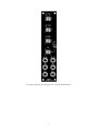
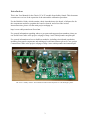
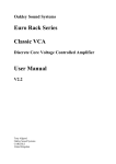
Oakley Sound Systems
5U Oakley Modular Series
Classic VCA
Discrete VCA PCB Issue 1
User Manual
V1.0.0
Tony Allgood
Oakley Sound Systems
CARLISLE
United Kingdom
The suggested front panel design for the 5U high MOTM format.
2
Introduction
This is the User Manual for the Classic VCA 5U module from Oakley Sound. This document
contains an overview of the operation of the unit and the calibration procedure
For the Builder's Guide, which contains a basic introduction to the board, a full parts list for
the components needed to populate the board or boards, and a list of the various
interconnections, please visit the main project webpage at:
http://www.oakleysound.com/5uvca.htm
For general information regarding where to get parts and suggested part numbers please see
our useful Parts Guide at the project webpage or http://www.oakleysound.com/parts.pdf.
For general information on how to build our modules, including circuit board population,
mounting front panel components and making up board interconnects please see our generic
Construction Guide at the project webpage or http://www.oakleysound.com/construct.pdf.
The issue 1 Oakley Classic VCA module behind a natural finish 1U wide Schaeffer panel.
3
The Oakley Classic VCA
This is a voltage controlled amplifier module inspired in part by a classic vintage design. The
Oakley Classic VCA is based on the ARP4019 sub-module which was used on the wooden
case ARP2600P semi-modular synthesiser. The design has a fully discrete core but uses opamps for input summing and the output drivers.
Two signal inputs are provided, one DC coupled and the other AC coupled. The former
allows audio and low frequency signals to be processed. While the latter has a high pass filter
so that it can be only used to process alternating frequencies. Both inputs can be used
simultaneously and each one features an input level control.
Two control voltage (CV) inputs are provided. CV1 is linear and is provided with a standard
attenuator pot that can control the sensitivity of the input. CV2 can be operated in either
exponential or linear mode.
CV2 features a reversible attenuator. When the pot is turned right of its central position, the
pot acts as a normal attenuator; increasing the sensitivity of the CV input. Left of centre, the
pot will act in inverting mode and the CV will be tipped upside down so that increasing
positive voltages will decrease the gain of the VCA.
When no input jack is inserted into the CV1 input, the CV1 pot becomes a gain control. This
allows the pot to be used as a simple volume control but when set high it also allows CV2 to
turn the VCA off.
The 5U version of the Classic VCA has two outputs. OUT A is the standard output of the
VCA. OUT B, gives you the difference signal between the sum of the two inputs and the final
output of the VCA. This is a sort of anti-output; when the VCA output signal goes up in level
this output goes lower. You can use it as a ring modulator (with gain pot set to max) or in
conjunction with OUT A as a voltage controlled pan.
4
Using the Classic VCA
What is a VCA?
The VCA (Voltage controlled Amplifier) is a device used to control the level of one signal by
the application of another. Traditionally, the controlled input to the VCA is called the INPUT,
whilst the controller input is called the CV, or control voltage. A typical system will have the
input as the audio output from a filter or oscillator, and the CV from an envelope generator.
As the envelope generator’s output voltage rises and falls, so the output of the VCA becomes
louder and softer. The output of the VCA is connected to the OUT A socket on the module.
It should be noted though that the CV input can actually be an audio input, and that the
INPUT can be a control voltage. It is up to you what you put into the module. The
nomenclature refers only to the original and common usage of the input sockets on a VCA
module.
The term amplifier is actually slightly different to the one you normally use too. It doesn't
always amplify in so far as it doesn't normally make the input signal bigger. The amplification,
or gain, actually varies from nearly zero, ie. the VCA is closed or off, to about one, or 0dB.
When the gain is one then the output level is the same as the input voltage. However, it is
possible to increase the gain of the VCA over one if the certain requirements are met – see
later for more details.
The signal inputs
The Oakley Classic VCA features two input signals, IN1 (DC) and IN2 (AC), and each has its
own level control. In this way, the Classic VCA can be used to mix or sum two signals
together before they are processed by the VCA core. One of the inputs, IN1 (DC), is directly
coupled to the VCA core. All signals, CV and audio, connected to this input can therefore be
controlled by the VCA. The other input, IN2 (AC), goes via a capacitor and so is often called
'AC coupled'. The capacitor acts to block very low frequency signals and steady state
voltages. You can think of it as being a high pass filter with a very low cut-off frequency.
The CV1 input and gain control
The CV1/GAIN pot controls the 'initial gain' of the module when no jack is inserted into CV1.
This is used to open and close the VCA manually, even when there are no other signals
applied to either of the CV inputs. If any positive CV is applied to CV2 then this will open the
VCA further. While the addition of a negative CV will actually cause the VCA to close.
With CV1/GAIN pot turned to its maximum value and no jacks inserted in either CV1 or CV2
then the gain produced by the VCA is 0dB or one.
The OUT B output works in reverse of the OUT A socket. When the GAIN pot is set to its
maximum the output level from OUT B should be at its minimum. However, you should note
that the signal is not completely silent. Unlike OUT A which can be shut off completely when
the VCA is closed, OUT B produces about -50dB of signal cut at its quietest. This is generally
good enough for its intended purposes of ring modulation and auto-panning.
5
Ring modulation is achieved by inserting a 'modulation' signal into CV2 with both the CV2
and CV1/GAIN pots set to their maximum and in LIN mode. Auto-panning, whereby an input
signal is moved back and forth between the left and right of a stereo signal, can be done by
utilising both OUT A and OUT B. Set the CV1/GAIN pot to the middle position which allows
the input signal(s) to be heard from both OUT A and OUT B. Then by applying a control
voltage to CV2 you should find that the audio signal moves between OUT A and OUT B.
As soon as a jack is inserted into CV1 then the CV1/GAIN pot now changes from a manual
gain pot to a modulation depth control for the CV1 input socket. The pot now controls the
sensitivity of the CV1 input. The CV 1 input is a linear control input.
5V at CV1, with the CV1/GAIN pot set to maximum, will make the gain of the VCA
approximately 0dB or unity. Any CV higher than this will increase the gain proportionately.
However, it should be noted that the output signal level of the VCA cannot exceed +/-12.5V
or so. This upper output limit is restricted by the power supply rails of the modular system.
CV1, or the actions of the GAIN pot, and CV2 will act together too, so it is entirely possible
to get gains of higher than unity if both are set high enough.
The CV2 input
For CV2 two modes are provided, LIN and EXP:
The LIN input has a linear response. This means that doubling the CV will double the output
amplitude. In general this is the most useful response for general VCA duties. With the
CV/GAIN pot at its minimum, and the CV2 pot at its maximum, +5V at the CV2 input will
produce a gain of around one, ie. 0dB or unity gain.
The EXP input has an exponential response. This means that a rising CV will produce a
proportional change in gain measured in decibels. In practice this means that the output signal
appears not to quickly increase in level until the input CV is close to 5V. This effect tends to
produce wonderfully plucky sounds when used with a conventional ADSR as the CV source.
6
Power supply requirements
The design requires plus and minus 15V supplies. The power supply should be adequately
regulated. The current consumption with no output signal is about +/-35mA. Power is routed
onto the PCB by a four way 0.156” MTA156 type connector or the special five way
Synthesizers.com MTA100 header.
Power connections – MOTM and Oakley
The PSU power socket is 0.156” MTA 4-way header. This system is compatible with MOTM.
Power
Pin number
+15V
Module GND
Earth/PAN
-15V
1
2
3
4
The earth/pan connection has been provided to allow the ground tags of the jack sockets to be
connected to the powers supply ground without using the module’s 0V supply. Earth loops
cannot occur through patch leads this way, although screening is maintained. Of course, this
can only work if all your modules follow this principle.
Power connections – Synthesizers.com
The PWR power socket is to be fitted if you are using the module with a Synthesizers.com
system. In this case the PSU header is not fitted. The PWR header is a six way 0.1” MTA, but
with the pin that is in location 2 removed. In this way location 3 is actually pin 2 on my
schematic, location 4 is actually pin 3 and so on.
Power
Location number
Schematic Pin number
+15V
Missing Pin
+5V
Module GND
-15V
Not connected
1
2
3
4
5
6
1
2
3
4
5
+5V is not used on this module, so location 3 (pin 2) is not actually connected to anything on
the PCB.
If the PSU header is fitted then pins 2 and 3 of PWR are linked together. This connects the
panel ground with the module ground.
7
Trimmers
Although you can use a simple fine bladed screwdriver for this adjusting the trimmers you
should really use a proper trimmer tool. Vishay, Bourns and others make trimmer adjusters for
less than a pound.
You should make sure your modular has been powered up for at least ten minutes prior to
calibration. Also, it is a good idea to have the room temperature close to what it would
normally be when playing your modular.
OFFSET: Turn the GAIN pot to its maximum level. Ensure all other pots are at their
minimum settings. Measure the output voltage from the output socket with a good digital
voltmeter. Adjust OFFSET with a jeweller's screwdriver or equivalent until the output voltage
is 0.000V +/- 5mV.
LIN: Insert a 5V peak triangle wave signal at roughly 440Hz to the IN1 (DC) input. Turn the
CV1/GAIN pot to the maximum and the IN1 (DC) and CV 2 pots to their middle positions.
Listen to the output of OUT B on your monitoring system. You should hear a slight
bleedthrough of the triangle wave input. Now adjust LIN until the signal level decreases to its
minimum. You may have to turn up the gain of your monitoring system to fine tune the null
point.
EXP: Insert a 5V peak triangle wave signal at roughly 440Hz to the IN1 (DC) input. Turn the
IN1 (DC) and CV2 pots to their maximum. All other pots should be at their minimum settings.
Connect a 5V source to the CV2 input. This could be a fixed voltage source, a triggered
envelope generator or midi-CV convertor – anything that will give you a +5V output signal.
Now with a scope measure the output voltage at OUT A and adjust EXP until the signal level
in EXP mode is the same as in LIN mode. It doesn't have to be that accurate – within 250mV
will be fine.
If you do not have a scope just simply listen to the OUT A signal and flip the switch from LIN
to EXP and adjust the EXP trimmer until there is no change in volume when you flip the
switch. It doesn't have to be that accurate, just try to get the two signals sounding roughly the
same.
If you can't get the levels equal then double check the voltage going into CV2. The EXP mode
is very sensitive to changes in level around 5V. If you can't get OUT A loud enough then the
voltage going into CV2 may well be lower than 5V. If it's too loud then the CV may well be
significantly over 5V.
8
Final Comments
I hope you enjoy using the Oakley Classic VCA
If you have any problems with the module, an excellent source of support is the Oakley Sound
Forum at Muffwiggler.com. Paul Darlow and I are on this group, as well as many other users
and builders of Oakley modules.
If you have a comment about this user manual, or have a found a mistake in it, then please do
let me know.
Last but not least, can I say a big thank you to all of you who helped and inspired me. Thanks
especially to all those nice people on the Synth-diy and Analogue Heaven mailing lists and to
those at Muffwiggler.com forum.
Tony Allgood at Oakley Sound
Cumbria, UK
© August 2012
No part of this document may be copied by whatever means without my permission.
9