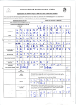
1
Multi Function Professional Puncher – A1 GB Operation Instructions Manual F Manuel d'instructions et d'utilisation E Manual de instrucciones de operación Part Number: 7715006 Revision number: 1 Issue Date: June 2015 Multi Function Professional Puncher – A1 English 3 Français 13 Español 23 GB Please read these instructions carefully and keep them in a safe place for future reference. F Lisez attentivement le présent manuel et conservez-le en lieu sûr afin de pouvoir le consulter en cas de besoin. E Lea estas instrucciones cuidadosamente y manténgalas en un lugar seguro para consulta en el futuro. Multi Function Professional Puncher – A1 GB TABLE OF CONTENTS 1. SAFETY INSTRUCTIONS 3 5. USER DISPLAY Important safeguards 3 6. PROBLEM SOLVING 9 Cleaning 3 7. 9 Service 4 8. DIE SET USER MANUAL Safety messages 4 2. INTRODUCTION 4 3. QUICK START GUIDE 5 4. USER OPERATIONS 6 SPECIFICATIONS 7 10 Important safeguards 1. SAFETY INSTRUCTIONS THE SAFETY OF YOU AND OTHERS IS VERY IMPORTANT TO CANON CORPORATION. IMPORTANT SAFETY MESSAGES AND INFORMATION ARE CONTAINED IN THIS MANUAL AS WELL AS ON THE MACHINE ITSELF. PLEASE MAKE SURE YOU CAREFULLY READ AND UNDERSTAND ALL OF THESE BEFORE OPERATING THE MACHINE. THE SAFETY ALERT SYMBOL PRECEDES EACH SAFETY MESSAGE IN THIS OPERATION INSTRUCTIONS MANUAL. THIS SYMBOL INDICATES A POTENTIAL PERSONAL SAFETY HAZARD THAT COULD HURT YOU OR OTHERS. THE FOLLOWING PICTORIAL IS FOUND ON THE PROFESSIONAL PUNCHER: This safety message means you could get an electrical shock because disconnecting power from this section does not cut off power from adjacent sections of the machine. Use the Professional Puncher only for its intended purpose of punching paper and covers according to the indicated specifications. Retain this Operation Instructions manual for future use. CAUTION: THE PRINTER ON/OFF SWITCH DOES NOT CUT OFF POWER FROM THE PUNCH. The Professional Puncher must be connected to a supply voltage corresponding to the electrical rating of the machine operation instructions (also listed on the serial number label). The grounding plug is a safety feature and will only fit into the proper grounding-type power outlet. If you are unable to insert the plug into an outlet, contact a qualified electrician to have a suitable outlet installed. Do not alter the plug on the end of the cordset (if provided) of the Professional Puncher. It is provided for your safety. Unplug the Professional Puncher before moving the machine or whenever the machine is not in use for an extended period of time. Do not operate the Professional Puncher if the machine has a damaged power supply cord or plug. Do not operate the machine after any malfunction. Do not operate the machine in case of liquid spills, or if the machine has been damaged in any other way. Do not overload electrical outlets beyond their capacity. To do so may result in fire or electrical shock. Cleaning This safety message means that you might get seriously hurt or killed if you open the product and expose yourself to hazardous voltage. NEVER remove the screwed on covers. ALWAYS refer service requirements to qualified service personnel. You may clean the exterior of the Professional Puncher using a soft, damp cloth. Do not use detergents or solvents as damage to the machine may occur. 3 Multi Function Professional Puncher – A1 GB Safety messages MAIN CORDSET SELECTION (THE FOLLOWING NOTE APPLIES ONLY TO THE UNITS RATED 230V 50Hz, AND LOCATED IN THE EUROPEAN UNION) CAUTION: WHEN CHOOSING A DETACHABLE LINE CORD FOR USE WITH YOUR PROFESSIONAL PUNCHER, ALWAYS FOLLOW THE FOLLOWING PRECAUTIONS These limits are designed to provide reasonable protection against harmful interference when the equipment is operated in a commercial environment. This equipment generates, uses, and can radiate radio frequency energy and, if not installed and used in accordance with the Operation Manual, may cause harmful interference with radio communications. Operation of this equipment in a residential area is likely to cause harmful interference in which case the user will be required to correct the interference at his/her own expense. CAUTION: CHANGES OR MODIFICATIONS NOT EXPRESSLY APPROVED BY GENERAL BINDING CORPORATION COULD VOID YOUR AUTHORITY TO OPERATE THE EQUIPMENT. The cordset consists of three parts: the attachment plug, the cord and the appliance inlet. Each of these components must have European regulatory safety approvals. The following minimum electrical ratings for the specific cordset are published for safety purposes. DO NOT USE CORDSETS THAT DO NOT MEET THE FOLLOWING MINIMUM ELECTRICAL REQUIREMENTS. PLUG: 3 amperes, 250 volts, 50/60 Hz, Class 1, 3 conductor, European safety approved. CORD: Type H05VV-F3G0.75, Harmonized (< HAR >). The “< >” symbols indicate cord approved according to appropriate European standard (NOTE: “HAR” may be substituted for approval mark of European safety agency that approved the cord. An example would be “< VDE >”). APPLIANCE CONNECTOR: 3 amperes, 250 volts, 50/60 Hz, European safety approved, Type IEC 320. The cordset shall not exceed 3 meters in length. A cordset with component electrical ratings greater than the minimum specified electrical ratings may be substituted. Service, Professional Puncher Do not attempt to service your Professional Puncher yourself. Contact an authorized service representative for any required repairs or major maintenance for your Professional Puncher. DO NOT REMOVE THE MACHINE’S COVER. There are NO user-serviceable parts inside the machine in order to avoid potential personal injury and/or damage to property or the machine itself. Service, Diesets 2. INTRODUCTION Thank you for purchasing the Professional Puncher. It is a versatile production system that will enable you to punch documents for a variety of binding styles by means of a simple die change. It has also been designed for easy operation. The Professional Puncher is an innovative solution for punching paper and offers the following design features: Quick-change die sets that can be interchanged without any tools. All Professional Puncher die sets include an Identification Label providing the user with the hole pattern and name. Convenient storage area for two extra Die Sets located above the sheet bypass. Duty Cycle and Product Positioning The CANON Multi Function Professional Puncher – A1 provides a flexible, cost effective punching solution for light to medium level punching production environments. It is designed for production print users that typically punch their documents at an average of 20-30% of their overall workflow. For customers that run continuous punching for long runs of over 4 hours, performance may vary or degrade due to a wide range of media weights and environmental conditions that can occur. Maximum Recommended Monthly Volume - The maximum recommended monthly punch volume should NOT exceed 400,000. Operating Die Set Supplies Every dieset is thoroughly oiled at the factory prior to shipping. Please note that it is normal for oil to be present on the first few punched sheets. During normal use this oil will be exhausted and should be replaced. As part of regular maintenance, each dieset should be oiled after approximately 100K punch cycles. Canon recommends use of brand 3-IN-ONE oil as it is readily available. Other light machine oils can also be used. To oil the dieset, refer to Section 8- Die Set User manual. Please note that it is normal for oil to be present on the first set of sheets punched after oiling the dieset. After approximately 25 to 50 sheets oil will no longer be found on the punched sheet. At this time the Professional Puncher can be utilized for punching of print jobs. See Section 8 Professional Puncher Dieset Manual for further instructions on servicing the Diesets. Dies are considered consumables and when worn, must be replaced since sharpening is not possible. Each die set has a 90-day warranty from the date of purchase. The warranty is void if the die is used beyond its specifications. Punch die life will be maximized if oiled every 100,000 punch cycles (see Dieset Service for details) Die sets have an expected use life of 750,000 punches using 20 lb/75 gsm paper. This is a minimum life expectation only. Die life is NOT guaranteed due to a wide range of media weights and environmental conditions that the dies may endure. If you are going to be punching extended runs that exceed the die use life, it is strongly recommended that you have sufficient numbers of the appropriate die sets on hand to continue with minimal downtime. Safety messages FCC NOTE (THE FOLLOWING NOTE ONLY APPLIES TO THE UNITS RATED 115V 60Hz.) This equipment has been tested and found to comply with the limits for a Class A digital device, pursuant to Part 15 of the FCC Rules. 4 Multi Function Professional Puncher – A1 GB 3. QUICK START GUIDE Professional Puncher must be connected to AC power to enable any feature of the machine. Below are three modes of operation of Professional Puncher. 1. Bypass Mode: This operation will allow paper to pass through the Professional Puncher without being punched. This is the default mode of operation for Professional Puncher. Make sure the Punch Icon is not selected in the printer’s User Interface. 2. Punch Mode: This operation will punch the trail edge of all sheets that pass through the Professional Puncher. Step 1: A properly configured die set must be inserted before running punch mode. See section 4.A for details on Die set changes and follow the labels on the die set for configuration. Step 2: Before starting a print job select the Punch mode from the printer’s UI. Professional Puncher will now function in Punch mode. 3. Crease Mode: This operation will crease in the middle of all sheets that pass through the Professional Puncher. Step 1: A Crease die-set must be inserted to enable the Crease mode. See section 4.A for details on Die set changes. Step 2: For some controllers, before starting a print job select the Crease mode from the printer’s UI. See printer manual. Professional Puncher will now function in Crease mode. Note: Crease mode is out of specification for certain printer configurations. UP DOWN ENTER/ OK Layout of Professional Puncher LCD User Interface 4. Die Set Configuration To configure the Die Set for the desired sheet size that is being processed see section 8 – Die Set User Manual. 5 Multi Function Professional Puncher – A1 GB A. 4. USER OPERATIONS i. Interchanging Die Sets: Are completed without tools and only take seconds to perform ii. Punch Chip Container: Note: For advanced Die Set Configuration instructions- See Section 8 Die Set User Manual. Easy-to-access chip tray for quick chip disposal iii. Removing Die Sets from the Machine: The inter-changeable die set slot of the Professional Puncher is located above the bypass section of the machine. Die Set Storage: Holds up to 2 spare Die Sets iv. Punch Bypass: Step 1: Stop the printer/copier. Short straight-through paper path for unpunched documents v. Interchanging Die Sets: Your Professional Puncher offers the convenience of interchangeable die sets, allowing you to economically punch documents for a wide variety of binding styles. Changing the machine's die sets is both quick and easy, as the following instructions illustrate: Step 2: Open the Professional Puncher access door panel. Punch Mode Path: Step 3: Securely grasp the die lock handle and rotate it in the CCW direction, as indicated in the label near the die lock handle. This releases the die from the locked position Wide radius turn can support stocks up to 300g/m2 cover Step 4: Slide the die set out until it is fully removed, supporting it with both hands. Step 5: Properly store the removed Die Set in the Die Set storage area of the Professional Puncher (keep away from dust, dirt, accidental falls from the edge of counters, etc.). Ciii Step 6: Select the desired Die Set for your new job and slide it into the Die Set slot. Push the Die set firmly until the Die stop feature contacts the round magnet. This is critical in ensuring the proper position of the die set. iv Step 7: Grasp the handle and rotate it in CW direction until the latch is fully engaged, as shown indicated in the label D WARNING: POSSIBLE PINCH POINT HAZARD. WHEN INSTALLING DIE SETS IN YOUR PROFESSIONAL PUNCHER, ALWAYS KEEP FINGERS AND OTHER BODY PARTS OUT OF THE MACHINE’S DIE SET SLOT AND AWAY FROM ALL AREAS OF THE DIE SET, EXCEPT FOR THE FINGER HOLE IN THE DIE SET. FAILURE TO FOLLOW THESE PRECAUTIONS MAY RESULT IN INJURY. Ev Step 8: Close the Access Door Panel. Step 9: Proceed with your printing and punching job. Ai Please note that when using a new die some oil will be present around the punched holes on the sheet. After punching 25 to 50 sheets the die will no longer leave oil on the sheets. It is recommended that a short test print job be run after installing a new die or a die that has recently been oiled. B. B ii Punch Chip Container: The Punch Chip Container for your Professional Puncher is located at the front of the machine’s base. The drawer should periodically be pulled out and emptied. The Professional Puncher uses a sensor to determine when the punch container is full. Once the punch container becomes full the LCD display shows “Chip Tray Full” message and a message also appear on the printers user interface screen. Paper flow and User Interactive sections of Professional Puncher 6 Multi Function Professional Puncher – A1 GB C. Paper Clearing: 5. USER DISPLAY When paper is jammed in the paper path of Professional Puncher the LCD display shows the area where a sheet(s) is jammed. Area Located on the top of the Professional Puncher is a user interactive LCD panel that provides Messages; Settings and Information relating to the functions of the punch unit. Description Area A If paper is jammed in the Punch Bypass, lift the handle until it latches with the locking mechanism. Reach and remove the jammed paper. To close the paper guide, press the upper latch lever while holding the guide plate handle and lower the guide plate to close it firmly. LCD Panel Overview Messages on the LCD Panel Area B1 If paper is jammed in the downward paper chute, move the chute to the right, reach in and remove the jammed paper. 1. Professional Puncher is ready to bypass, sheets will not be punched. 2. 3. Ensure the paper chute is closed. Area B4 If paper is jammed in the upward paper chute, move the door to the left, reach in and remove the jammed paper. Ensure the paper chute is closed. Ready To Crease Professional Puncher is ready to process a crease job. For some controllers, all sheets through the unit will be creased. 4. Running Bypass This is displayed when Bypass mode is in operation. 5. Running Punch This is displayed when Punch mode is in operation. 6. Area B3 If paper is jammed in the left bottom chute, unlatch the chute, reach in and remove any jammed paper. Ready To Punch Professional Puncher is ready to process a punch job, all sheets through the unit will be punched. Ensure the paper chute is closed. Area B2 If paper is jammed in the right bottom chute, press the top lever while holding the bottom lever. This will unlatch the chute; continue to open the chute until it reached the magnet on the right side. Reach in and remove the paper. To return the chute to the closed position, move it back in the opposite direction until the latch mechanism is activated. Ensure the paper chute is closed. Ready Bypass Running Crease This is displayed when Crease mode is in operation. 7. Chip tray Full When the punch container becomes full of waste paper chips, this message will be displayed. 8. Chip tray Out When the punch container is removed or not fully inserted into the punch unit, this message will be displayed. 9. Check die When the Die Set is removed or not fully inserted into the punch unit, this message will be displayed. When this message is displayed the punch unit will run in Bypass mode only. 10. Close Door Area B2/B3 Before uninstalling the die set, ensure Area B2 and B3 are cleared of any jammed paper. If there is jammed paper cannot be removed from Area B2 and B3, uninstall the die set to remove the jammed paper. (see Section 4. Changing the Interchangable die sets) When the Front door is open or not completely closed this message will be displayed. 11. Paper jam When a sheet of paper becomes jammed within the punch unit, this message is displayed. See the section of this manual titled PAPER CLEARING for instructions on how to remove a jammed sheet 7 Multi Function Professional Puncher – A1 GB “+” ON THE LCD INCREASES ALIGNMENT OFFSET Changing the Settings on the LCD panel 1. Mode With Crease die inserted, crease function can be turned ON/OFF. 2. ALIGNEMENT Backgage Depth Setting Backgage is the distance of the punched hole(s) from the trail edge of the sheet. This distance can be adjusted by entering the Settings section (press Up or Down from the Home screen, and press OK for Settings). Pressing Up arrow will increase the Depth of Backgage, and Pressing Down arrow will decrease the Depth of Backgage. “-” ON THE LCD DECREASES ALIGNMENT OFFSET BACKGAGE “-”ON THE LCD DECREASES BACKGAGE DEPTH “+”ON THE LCD INCREASES BACKGAGE DEPTH 4. Clear Cover The Backgage Depth setting and Alignment setting for Clear Cover media can be adjusted using this function. 5. Language The LCD panel can be configured to display one of the following languages: English; Francais; Espanol; Deutsch or Italiano. When a crease die is inserted, the Backgage Depth options is: 1 Crease Mid Displaying Information on the LCD Panel 1. Die type The type of die set that is presently installed in the machine will be displayed. 2. Punch cycles This is the total number of punched sheets the system has processed. 3. Firmware This displays the current level of firmware of Professional Puncher. 3. Alignment Setting Alignment is the distance of the Top punched hole from the side edge of the sheet (viewed from the punch output orientation). This distance can be adjusted by entering the Settings section (press Up or Down arrow from the Home screen, and press OK for Settings). Pressing Up arrow will increase the Alignment position, and Pressing Down arrow will decrease the Alignment position. 8 Multi Function Professional Puncher – A1 GB 6. PROBLEM SOLVING 7. SPECIFICATIONS Probable Cause Probable Cause No power, won’t punch Power cord not attached to back of machine or not properly plugged into the wall. Power On/Off activated Punch and Crease Sheet Size and Edge Switch not Punched holes not aligned with the edge of the paper Follow instructions on die set labels to properly configure the die for a specific sheet size Sheet jamming repeatedly at die set area. Remove the die-set, inspect the die throat to see if there is any stuck paper chad. Insert Chip tray message on the LCD interface. LEF- Long Edge Fed SEF- Short Edge Fed US Sizes LTR LEF LTR SEF 8-½ x 5-½ LEF Legal SEF 11x17 SEF 9" x 12" SEF 9” x 12” LEF 12" x 18" SEF 12.6” x 19.2” 13” x 19” 13” x 19.2” ISO sizes A4 LEF A4 SEF A5 LEF A3 SEF SRA4 SEF SRA4 LEF SRA3 SEF Make sure the Chip tray is fully inserted. Tab Stock Punch only Punch only Punch only Punch only Crease only Crease only Crease only Punch only Punch only Punch only Punch only US Sizes LTR, with 3, 4, 5, 8, 10, 12, 25*, 26*, 27* tabs: 160gsm – 300 gsm 8-½ x 5-½, with 3,5 tabs ISO Sizes A4, with 5,10, 12, 25*, 26*, 27* tabs: 160-300gsm A5, with 3,5 tabs Paper Stock Plain: 75gsm - 300gsm (20# bond to 110# cover) Coated: 120gsm - 300gsm (32# bond to 110# cover) Clear Cover 7mil Paper Bypass Mode Sheet size Paper sizes and stocks same as printer Punch Capacity Single Sheet Power Supply 115V, 60Hz, Single Phase Electrical Amps and Frequency Safety Certification cULus Dimensions L: 795mm; W: 445mm; H: 1040mm L: 31.5"; W: 17.5"; H: 41" Weight 102 kg 115V: 3.8A; 60Hz 225 lbs Shipping Weight 135 kg 298 lbs. Manufactured Assembled in Taiwan 9 Multi Function Professional Puncher – A1 GB Remove the pressure bar and set aside. 8. DIE SET USER MANUAL The die sets for the Professional Puncher are intended to work with multiple paper sizes and sheet feed directions. In order to accommodate different sheet sizes this die set must be configured to the correct number of punching pins and the die stop must be set to the proper position. The die label contains information on the common paper punching sizes, for uncommon sizes please refer to Table 8.1. Figure 8.3 Pressure Bar Glossary LEF- Long Edge Feed- Indicates that the paper is being fed through the machine so that the longer side of the sheet will be punched. SEF- Short Edge Feed- Indicates that the paper is being fed through the machine so that the shorter side of the sheet will be punched. Statement Paper- 8.5" X 5.5" Legal Paper- 8.5" X 14" Ledger Paper- 11" X 17" Pin Numbering Die punching pins are numbered sequentially starting from the handle end. Figure 8.1 shows a 47 hole coil die as an example. All square and round hole die sets follow the same pin numbering format. Figure 8.4 Pin Removal Note: Lubricating oil may be present on the die pins, wear gloves if needed. Lift up and remove the desired pins according to Table 8.1. Store pins in the pin storage tray inside front door of machine making sure pins cannot be dropped, damaged or lost while removed. Dowel Pin Holes Pin #1 Pin #47 Figure 8.5 Replace Pressure Bar Figure 8.1 Coil Die Set Pin Numbering Replace the pressure bar by lining up dowel pin holes with exposed dowel pins. Hold pressure bar so that it is seats completely over dowel pins and then rotate Quarter Turn Fasteners clockwise until a click is felt to lock pressure bar in position. The pressure bar can be locked only if the orientation is correct, it cannot be locked in any other orientation. Important! Make sure pressure bar is attached and both Quarter Turn Fasteners are in the locked position prior to inserting the die set into the machine or serious damage can occur to both the machine and die set. Quarter Turn Fastener Figure 8.2 Pressure Bar Removal To remove punch pins from the Professional Puncher first turn the two Quarter Turn Fasteners CCW direction to release the pressure bar. Pin Removal US Paper Sizes Canon Part Number LTR LEF LTR SEF STATEMENT LEF LEGAL SEF LEDGER SEF 9" x 12" LEF 9" x 12" SEF 12" x 18" SEF Coil Rnd 2, 47 7, 42 7, 42 7, 42 2, 47 1, 2, 47 6, 7, 42, 43 1, 2, 47 Coil Rnd ISO Paper Sizes Canon Part Number A4 LEF A4 SEF A5 LEF A3 SEF SRA4 LEF SRA4 SEF SRA3 SEF NONE 7, 41 7, 41 NONE NONE 6, 7, 42, 41 NONE Wire 2:1 Rnd 1, 23 NONE NONE NONE 1, 23 1, 23 3, 21 1, 23 Wire 2:1 Rnd NONE 4, 21 4, 21 NONE NONE 4, 21 NONE Wire 3:1 Rnd 1, 34 5, 31 5, 31 5, 31 1, 34 1, 34 5, 31 1, 34 Wire 3:1 Rnd NONE 5, 30 5, 30 NONE NONE 4, 5, 30, 31 NONE 3 Hole 8mm NONE N/A N/A N/A NONE NONE N/A NONE 3 Hole 8mm N/A N/A N/A N/A N/A N/A N/A 3/5/7 2/4 2/4 2/4 VeloBind Hole Hole Hole Hole 11 Hole 8mm 8mm 6.5mm SCAN LTR Pin Numbers to Remove Based On Paper Size or Orientation 3H/5H/7H N/A N/A N/A 3H/5H/7H 3H/5H/7H N/A 3H/5H/7H N/A N/A N/A N/A N/A N/A N/A N/A N/A N/A N/A N/A N/A N/A N/A N/A N/A N/A N/A N/A N/A N/A N/A N/A NONE N/A N/A N/A NONE NONE N/A NONE 3/5/7 2/4 2/4 2/4 VeloBind Hole Hole Hole Hole 11 Hole 8mm 8mm 6.5mm SCAN LTR Pin Numbers to Remove Based On Paper Size or Orientation N/A N/A N/A N/A N/A N/A N/A 2H/4H 2H 2H 2H/4H 2H/4H N/A 2H/4H 2H/4H 2H 2H 2H/4H 2H/4H N/A 2H/4H NONE NONE NONE NONE NONE NONE NONE N/A N/A N/A N/A N/A N/A N/A VeloBind 12 Hole A4 N/A N/A N/A N/A N/A N/A N/A N/A VeloBind 12 Hole A4 NONE N/A N/A NONE NONE N/A NONE CombBind 1, 21 NONE NONE NONE 1, 21 1, 21 3, 19 1, 21 CombBind NONE 4, 19 4,19 NONE NONE 4, 19 NONE Wire 2:1 Sq 1, 23 NONE NONE NONE 1, 23 1, 23 3, 21 1, 23 Wire 2:1 Sq NONE 4, 21 4, 21 NONE NONE 4, 21 NONE Wire 3:1 Sq 1,34 5,31 5,31 5,31 1, 34 1, 34 5, 31 1, 34 Wire 3:1 Sq NONE 5, 30 5, 30 NONE NONE 4, 5, 30, 31 NONE Table 8.1 Pin Removal Guide The above chart shows the information on which pins need to be removed to correctly punch each sheet size and configuration that the Professional Puncher can accept. For standard offering dies not found in the chart no pin adjustment is necessary *For CombBind 20H Configuration Pull Pin Number 1 10 Multi Function Professional Puncher – A1 GB Pin Addition The process for adding punch pins is the same as pin removal except that pins are added and not removed once the pressure bar is off. When replacing punch pins make certain that the pins are completely seated against the pin retainer prior to reattaching the pressure bar. Position B Die Stop Knob Die Stop Handle Label CORRECT INCORRECT Position A Figure 8.7 Coil Die Stop Position Die Set Maintenance CORRECT The die sets must be periodically oiled and greased to maintain proper functionality and prevent premature failure of the die set. The die set should be oiled and inspected every 100K cycles. INCORRECT Figure 8.6 Pin Addition Die Stop Position On some of the Professional Puncher die sets there is an adjustable die stop which is used to re-center the die set for certain sheet sizes, as shown in Figure 8.7. For die sets without a die stop knob there is no die stop position adjustment necessary. For units with a die stop knob, the die stop must be set to the correct position or the punched holes will not be centered on the sheet. The common paper sizes are shown on the die stop handle label below the die stop knob, for the uncommon paper sizes please refer to Table 8.2. Position A is when the arrow on the die stop knob points down towards the handle and lines up with the lower arrow on the die stop handle label. Position B is when the arrow on the die stop knob points to the side and lines up with the side arrow on the die stop handle label. (See Figure 8.7) To change the die stop position first remove the die from the machine and place on a flat stable surface. While holding the die in a stable position push down on the die stop knob until the knob is free to rotate. Then turn the knob until the arrow on the knob lines up with the desired arrow on the die stop handle label. Once the arrows line up, release the die stop knob making sure that the metal die stop on the bottom fully seats against the die plate. To lubricate die set pins that do not have felt pads: 1. Apply a drop (0.05 ml) of 3-IN-ONE or high quality light machine oil directly to the pins. 2. Depress the top portion of the die set so that the pins protrude from the bottom plate. 3. Wipe clean, leaving a light coat of oil on them. 4. Wipe up any oil that remains on the top of the plates To lubricate die set pins that have felt pads: 1. Lubricate with 3-IN-ONE oil or a high quality light machine oil. 2. Apply a 1/8” (3 mm) bead of oil lightly along the length of the felt pad [1], but do not over saturate. 3. Do not use spray lubricants because they tend to dry up quickly and leave a sticky residue. Oil from the die may blemish the first few punched sheets after oil has been applied. Run test punched copies until clean copies can be made. Wire Wire Wire Wire 2:1 3:1 CombBind 2:1 3:1 Rnd Rnd Sq Sq Die Stop Position Based On Paper Size or Orientation Coil Rnd US Paper Sizes Canon Part Number LTR LEF LTR SEF STATEMENT LEF LEGAL SEF LEDGER SEF 9" x 12" LEF 9" x 12" SEF 12" x 18" SEF B B B B B B B B A A A A A A A A A B B B A A B A A A A A A A A A A A A A A A A A A B B B A A B A Wire Wire Wire Wire 2:1 3:1 CombBind 2:1 3:1 Rnd Rnd Sq Sq Die Stop Position Based On Paper Size or Orientation Figure 8.8 Lubrication Coil Rnd ISO Paper Sizes Canon Part Number A4 LEF A4 SEF A5 LEF A3 SEF SRA4 LEF SRA4 SEF SRA3 SEF A A A A A A A A B B A A B A A A A A A A A A* B B A* A* B A* Table 8.2 Die Stop Position Guide *For CombBind 20H Configuration set to die stop position B A B B A A B A A A A A A A A End of Die Life If a die set is at the end of its life it will tend to cause paper jams due to hanging paper chips. This is a result of die plate wear and not pin wear, which cannot be corrected. When this occurs, the die set must be replaced with a new one. Attempting to replace or sharpen pins will not correct the issue and therefore is not recommended. Die Set Handling There is a chipset located in the die set which should not be touched during die set handling. Do not attempt to touch the chipset reader located inside the machine as this may result in damage to the punch. 11 Multi Function Professional Puncher – A1 Professional Puncher Die Sets GB The Professional Puncher uses a variety of easily interchangeable die sets that allow you to punch documents in line for several different binding styles. By selecting the appropriate die set, you can use your Professional Puncher to punch documents in any of the following binding styles. Die Set Description For Plastic Comb Binding Canon Part Number High Durability Option available 1 19-LTR 21-A4 Die, Canon, Comb Bind Die, Canon, Comb Bind, HD PB Plastic Bind; Hole Size: 8mm x 2.9mm (0.313" x 0.116") (LxW); Center-to-Center Hole Spacing: 14.3mm (0.563") For Twin Loop™ Binding: 1 32-LTR 34-A4 Die, Canon, Wire 3.1, Sq. W3 Wire; Square; 3 Holes per inch; Hole Size: 4mm x 4mm (0.156" x 0.156") (L x W); Center-to-Center Hole Spacing: 8.5mm (0.333") 1 21-LTR 23-A4 Die, Canon, Wire 2.1, Sq. W2 Wire; Rectangle; 2 Holes per inch; Hole Size: 6.4mm x 5.4mm (0.250" x 0.214")(L xW); Center-to-Center Hole Spacing: 12.7mm (0.500") 32-LTR 34-A4 1 Die, Canon, Wire, 3:1, Rnd. W3 Wire; Round; 3 Holes per inch; Hole Size: 4mm (0.158") Diameter; Center-to-Center Hole Spacing: 8.5mm (0.335") 1 23-A4 21-LTR Die, Canon, Wire, 2:1, Rnd. W2 Wire; Round; 2 Holes per inch; Hole Size: 6.5mm (0.0.256") Diameter; Center-to-Center Hole Spacing: 12.7mm (0.5") For Color Coil™ Binding: High Durability option available 44-LTR 47-A4 1 Die, Canon, Coil, Rnd. Die, Canon, Coil, Rnd, HD C4 Coil; Round; 4 Holes per inch; Hole Size: 4.4mm (0.174") Diameter; Center-to-Center Hole Spacing: 6.3mm (0.2475") For Velo® Bind: 1 11 Die, Canon, Velobind®, 11 Holes, Ltr. VB Velobind®; Round; 1 Hole per inch Hole Size: 3.2mm (0.125") Diameter; Center-to-Center Hole Spacing: 25.4mm (1") 1 12 Die, Canon, Velobind®, 12 Holes, A4. VB Velobind®; Round; 1 Hole per inch Hole Size: 3.2mm (0.126") Diameter; Center-to-Center Hole Spacing: 25.4mm (1") For Loose Leaf Binding: High Durability option available for 3 Ring 1 3 Die, Canon, 3 Hole, 8mm Die, Canon, 3 Hole, 8mm, HD 3 Ring Binder; U.S. (Standard Loose-leaf Patterns); Hole Size: 8mm (0.316") Diameter 1 7 Die, Canon, 3/5/7 Hole, 8mm 3 Ring, 5 Ring, 7 Ring; U.S. (Standard Loose-leaf Patterns); Hole Size: 8mm (0.316") Diameter 1 4 Die, Canon, 4 Hole, 8mm 4 Ring Binder; European (Standard Loose-leaf Patterns); Hole Size: 8mm (0.315") Diameter 1 4 Die, Canon, 4 Hole, 6.5mm 4 Ring Binder; European (Standard Loose-leaf Patterns); Hole Size: 6.5mm (0.256") Diameter Die, Canon, 4 Hole, Scan 4 Ring Binder; Scandinavian (Standard Loose-leaf Patterns); Hole Size: 6.5mm (0.256") Diameter Graphics do not represent actual punch pattern dimensions or spacing. For Creasing: Die, Canon, Crease Crease 12