1
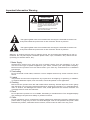
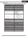
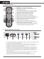
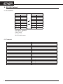
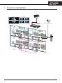
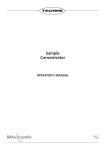
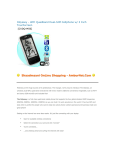
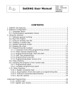
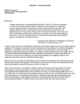
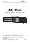
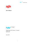
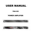
High Definition Digital Video Wall LED Monitor Operating Instructions Model No.: CVW-47SDI2 Operation Instructions Thank you for purchasing this product. For optimum performance and safety, please read these instructions carefully. Before connecting, operating or adjusting this product, please read these instructions completely. Please keep this manual for future reference. Table of Contents 1. Specifications....................................................................1 2. Remote Control.................................................................2 3. Signal Input / Output Terminals.........................................2 4. Using Your LED Display....................................................3 5. Using the OSD menu........................................................4 5.1 Picture Menu...............................................................5 5.2 Setup Menu.................................................................5 6. RS-232 Protocol................................................................6 6.1 Piin Definition..............................................................6 6.2 Command...................................................................6 7. Connection and Installation............................................... 7 Disclaimers The information in this manual has been carefully checked and is believed to be accurate. Cypress Technology assumes no responsibility for any infringements of patents or other rights of third parties which may result from its use. Cypress Technology assumes no responsibility for any inaccuracies that may be contained in this document. Cypress also makes no commitment to update or to keep current the information contained in this document. Cypress Technology reserves the right to make improvements to this document and/or product at any time and without notice. Copyright Notice No part of this document may be reproduced, transmitted, transcribed, stored in a retrieval system, or any of its part translated into any language or computer file, in any form or by any means - electronic, mechanical, magnetic, optical, chemical, manual, or otherwise - without express written permission and consent from Cypress Technology. © Copyright 2011 by Cypress Technology. All Rights Reserved. Version 1.0 June 2011 Trademark Acknowledgments All products or service names mentioned in this document may be trademarks of the companies with which they are associated. Safety Precautions Please read all instructions before attempting to unpack or install or operate this equipment, and before connecting the power supply. Please keep the following in mind as you unpack and install this equipment: Always follow basic safety precautions to reduce the risk of fire, electrical shock and injury to persons. To prevent fire or shock hazard, do not expose the unit to rain, moisture or install this product near water. Never spill liquid of any kind on or into this product. Never push an object of any kind into this product through module openings or empty slots, as you may damage parts. Do not attach the power supply cabling to building surfaces. Do not allow anything to rest on the power cabling or allow it to be abused by persons walking on it. To protect the equipment from overheating, do not block the slots and openings in the module housing that provide ventilation. Revision History Version No Date Summary of Change VR0 20121114 Preliminary Release Important Information Warning CAUTION RISK OF ELECTRIC SHOCK DO NOT OPEN CAUTION: TO REDUCE THE RISK OF ELECTRIC SHOCK, DO NOT REMOVE SCREWS. NO USER-SERVICEABLE PARTS INSIDE. REFER SERVICING TO QUALIFIED SERVICE PERSONNEL. The lightning flash with arrow-head within a triangle is intended to tell the use that parts inside the product are a risk of electric shock to persons. The lightning flash with arrow-head within a triangle is intended to tell the use that parts inside the product are a risk of electric shock to persons. Warning: To reduce the risk of fire or electric shock, do not expose this apparatus to rain or moisture. Do not place liquid containers (flower vase, cups, cosmetics, etc.) above the set (including on shelves above, etc.). 1. Mains Supply Operate this product only from the type of power supply from the package. If you are not sure of the type of power supplied to your home, consult your local power company. Disconnect the product from the mains before your start any maintenance or installation procedures. 2. Overloading Do not overload a wall outlet, extension cord or adapter as this may result in electric fire or shock. 3. Liquids The product should not be exposed to any liquids such as dripping or splashing. In addition, no objects filled with liquids, such as vases, should be placed on the apparatus. 4. Cleaning Disconnect the product from the wall outlet before cleaning. Please wipe the screen gently with soft cloth. Do not using chemical solvents to cleaning the product, e.g. methylbenzene, resin or alcohol, will damage the exterior case, tinted glass and the remote controller. Do not apply them to clean this machine. 5. Place Do not place the product on an unstable, fluctuating or tilt table stand. The dropped display may endanger the personnel safety or product functions. 6. Cable Do not intertwine, pull or compress the power cable when placing the product, otherwise the power cable or plug may be worn out and damaged. And do not presses the power cable beneath the product, otherwise electric shocks, short circuits or flash over may occur. 4 WWW.CYPRESS.COM.TW 1. Specifications Model. No SPECIFICATION Screen Size (inches) Aspect Ratio Contrast Ratio Viewing angle range Panel Resolution Response Time (ms) Brightness VIDEO HDMI Compatibility HDTV Compatibility PC Resolution SDI Timing & Distance Progressive Scan Video Noise Reduction 3D-Y/C Digital Comb Filter Color Purity Optimizer (3D Color Management) Motion Pattern Noise Reduction INPUT/OUTPUT HDMI Interface PC Input (for PC) SDI GENERAL Power Supply Power Consumption (W) On Screen Display Languages Dimension (H x V x D) mm Package Dimension (H x V x D)mm Net Weight (KG) Gross Weight (KG) Accessory Power Cord Remote Control with Batteries User Manual Warranty Card WWW.CYPRESS.COM.TW CVW-CVW-47SDI2 47 16:9 1400:1 178° 1366*768 12 700cd/M2 480p/576p/720p/1080i/1080p Up to 1080P 640x480@60,72,75 800x600@56,60,72,75 1024x768@60,70,75 1280x1024@60,75 1360x768@60 1920x1080@60 SD-SDI: SMPTE 259M-C, 270 Mbit/s up to 300m HD-SDI: SMPTE292M, 1.485 &1.485/1.001 Gbit/s up to 200m 3G-SDI: SMPTE 424M/425M-AB, 2.970 & 2.970/1.001 Gbit/s up to 300m Yes Yes Yes Yes Yes 2 rear 1 rear 2 rear (1 in, 1 out) 100V~240V 180 English 1046 x 591 x 115 1185 x 745 x 215 20.4 21 1 Yes Yes Yes 1 2. Remote Control ① ② ① POWER: Turn on the power of the monitor. ② POWER OFF: Turn off the power of the monitor. ③ SINGLE: Press this button to switch the output image to ③ ④ ④ ⑤ ⑥ ⑦ ⑧ ⑩ ⑪ ⑬ ⑭ ⑤ ⑥ ⑦ ⑧ ⑨ ⑩ ⑪ ⑫ ⑨ ⑫ ⑬ ⑮ ⑭ ⑮ single display per monitor. 2x2/3x3/4x4/5x5:Press thess buttons to switch the output image to 2x2/3x3/4x/3x2/4x3 or 5x5 displays per image. ▲/▼: Adjust or select OSD menu up and down. ◄/►: Adjust or select OSD menu left and right. OK: Press this button to confirm the selection. RETURN: Exit the OSD menu or the selection. MENU: Display the OSD (On Screen Display) menu. HDMI1/2: Press this hot key to switch the input to HDMI I/2. VGA: Press this hot key to switch the input to VGA. U/OVER: Press this key to adjust the screen when the image is underscan or overscan. SDI: Press this hot key to switch the input to SDI. OPTION: Press this key to switch to the special setting of the display image set by the factory design. FAC:Press this key to enter into the factory mode. This is not a normal entry therefore, do not press this key unless it is adviced and guide by the special technician. 3. Signal Input/Output Terminals ⑦ ⑧ ① ② ③ ④ ⑤ ⑥ ①AC IN: Connect the power cord with the power adaptor included in the package and plug it into the wall outlet for the power supply. ②HDMI IN 1/2: Connect the HDMI cable from DVD/Blu-ray player for signal input. ③VGA IN: Connect the D-Sub 15pin cable from the PC/NB device or with RGB to D-Sub adaptor from the AV device for video signal input. ④RS-232 IN: Connect the D-Sub 9pin cable from PC/NB device for RS-232 control. ⑤RS-232 OUT: Connect the D-Sub 9pin cable to the next video/TV wall panel's(suggest using the same family type) RS-232 IN for unit signal distribution and displaying. ⑥IR in: Connect the IR extender included in the package for receiving remote control's signal of the device. ⑦SDI OUT: Connect the SDI cable to the next video/TV wall panel's(suggest using the same family type) SDI IN for unit signal distribution and displaying. ⑧SDI IN: Connect the SDI cable from the SDI source equipment for signal input. 2 WWW.CYPRESS.COM.TW 4. Using Your LED Display +-+ Refer to the owner's manual of any external equipment to be connected. When connecting any external equipment, do not connect any AC power cord to wall outlets until all other connections are completed. 1. Connect all AC power sources. 2. Installing the AAA size batteries in your remote control. Step 1. Slide the back cover up to open the battery compartment of the remote control. Step 2. Insert two AAA size batteries. Make sure to match the (+) and (-) ends of the batteries with the (+) and (-) ends indicated in the battery compartment. Step 3. Slide the cover back into place. Do not use caustic cleaners (Porcelain, stainless steel, toilet, or oven cleaner etc.) on the remote, as it may suffer damage. 3. Press the [POWER] button on the remote to turn on the LED Display. Monitor 7M 30° 30° 3M 3M Monitor WWW.CYPRESS.COM.TW 3 5. Using the OSD menu Press [MENU]. Press [▲ / ▼] to highlight an option. Press [OK] to confirm the selection. 5.1 Picture Menu Press [▲ / ▼] to highlight an option. Press [◄ / ►] to adjust. Press [OK] to confirm the selection. Press [RETURN] to exit menu. Option Picture Mode Standard Colour Tint Sharpness Contrast Brightness 4 Description To adjust picture mode to: Vivid / Normal / Cinema / User ON/OFF, when slelct to ON the system will go back to initial setup To adjust the color saturation. To adjust picture hue (NTSC only). Sharpen of soften the picture. To increase or decrease picture contrast. To adjust for brighten or darken the picture. WWW.CYPRESS.COM.TW 5.2 Setup Menu Press [▲ / ▼] to highlight an option. Press [◄ / ►] to adjust. Press [OK] to confirm the selection. Press [RETURN] to exit menu. Option Description Language Select the OSD display language (English, Traditional Chinese and Simplify Chinese). Standard Set it to ON will allow system to set the setup menu into the default value as indicated in the in the above diagram. H Position Start To set the total value of the horizontal value of the video/TV wall. This function is made to adjust for the standard monitor screen. V Position Start To set the total value of the vertical value of the video/TV wall. This function is made to adjust for the wide monitor screen. H Zoom Size To set the total value of the horizontal zoom in and zoo out size of the video/TV wall. This function is made to enlarge the image or to shrink the image. V Zoom Size To set the total value of the vertical zoom in and zoo out size of the video/TV wall. This function is made to enlarge the image or to shrink the image. H Blanking Edit This function is to set the total value of the horizontal value of the banking area of the video/TV wall. This function is made to adjust the image according to display's frame. V Blanking Edit This function is to set the total value of the vertical value of the banking area of the video/TV wall. This function is made to adjust the image according to display's frame. TV Position Width This function is to set the numbers of the TV/display that is to be on a horizontal line of the TV wall. TV Position Height This function is to set the numbers of the TV/display that is to be on a vertical line of the TV wall. Back Light This function is to set the back light of the TV panel from the highest figure of 0 with the brightest light to the lowest figure of 230 with darkest light. WWW.CYPRESS.COM.TW 5 6. RS-232 Protocol 6.1 Pin Definition Pin Pin Pin Pin Pin Pin Pin Pin Pin RS-232 IN 1 NC 2 TxD 3 RxD 4 NC 5 GND 6 NC Connect to 7 Pin 8 Connect to 8 Pin 7 9 NC RS-232 OUT Pin 1 NC Pin 2 RxD Pin 3 TxD Pin 4 NC Pin 5 GND Pin 6 NC Connect to Pin 7 Pin 8 Connect to Pin 8 Pin 7 Pin 9 NC Baud Rate: 19200bps Data bit: 8 bits Parity: None Stop Bit: 1 bit Flow Control: None 6.2 Command COMMAND 0x23 0x53 0x30 0x30 0x31 0x23 0x23 0x53 0x30 0x30 0x30 0x23 0x23 0x43 0x30 0x30 0x01 0x23 0x23 0x43 0x30 0x30 0x00 0x23 0x23 0x43 0x52 0x11 0x00 0x23 0x23 0x43 0x52 0x22 0x00 0x23 0x23 0x43 0x52 0x33 0x00 0x23 0x23 0x43 0x52 0x44 0x00 0x23 0x23 0x43 0x52 0x55 0x00 0x23 0x23 0x43 0x52 0x32 0x00 0x23 0x23 0x43 0x52 0x43 0x00 0x23 0xEF 0x05 0x00 0xC0 0x22 0xEE 0xEF 0x05 0x01 0xC0 0x22 0xEE 0xEF 0x05 0x03 0xC0 0x22 0xEE 0xEF 0x05 0x02 0xC0 0x22 0xEE 6 ACTION POWER ON POWER OFF UNDER SCAN OVER SCAN SINGLE 2x2 3x3 4x4 5x5 3x2 4x3 Change to HDMI 1 Change to HDMI 2 Change to PC Change to SDI WWW.CYPRESS.COM.TW 7. Connection and Installation FULL SINGLE ① ② ① ② ④ ③ ④ ③ PS3 CHDMI-4M (HDMI Splitter) (HDMI 分配器) SDI SECURITY CAMERA 2 SDI OU T 1 SDI IN HDMI 1 SDI OU T HDMI 2 SDI IN POWER OFF POWER SINGLE 3 HDMI HDMI 1 2X2 3X3 4X4 3X2 4x3 5x5 FULL HDMI 2 OK SDI OU T 4 IR線 IR HDMI RETURN MENU HDMI1/2 VGA U/OVER SDI OPTION FAC CR-107 SDI IN SDI OU T HDMI 1 HDMI 2 SDI IN HDMI HDMI 1 HDMI 2 HDMI WWW.CYPRESS.COM.TW 7 A. Prepare the TV / Panel Keep all the parts properly for future installation purpose. 1.Separate the fixed rack from both side * To avoid scratch or demage of the panel, it is suggested to place the panel on a flat table that is covered with soft cotton pad. * As show in the diagram 1, remove the screws (x4) from the fixed rack (x2) of both side. Fied Rack Rack's Screw Fied Rack Rack's Screw Diagram 1 As show in the picture is for reference only, please see the actual goods for standard. 2. Separate the support rack from the fixed rack * As show in the diagram 2, remove the support rack's screw (x4) from the fixed rack (x2) of both side. 3. Fix the fixed rack on * Keep the support rack and all the removed screws properly for future installation purpose and fix the fixed rack on the back of the panel as to diagram 3 show with the screws included in the panel's parts package. Screws from panel's parts package Fied Rack Support Rack's screw Screws from panel's parts package Support Rack Diagram 2 Diagram 3 4.Wall Mount Screws * 4pcs of wall mount screews are the parts from the wall mount frame, put them on back of the panal with flat screwdriver as show in diagram 4. Wall Mount Screws Diagram 4 As show in the picture is for reference only, please see the actual goods for standard. MPM-CVW47SDI