1
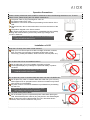
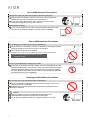
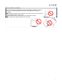
FCC Information
This device complies with Part 15 of the FCC Rules. Operation is subject to the following two conditions:
(1) This device may not cause harmful interference, and (2) this device must accept any interference received,
including interference that may cause undesired operation. This equipment has been tested and found to
comply with the limits for a class B digital device, pursuant to Part 15 of the FCC Rules.
These limits are designed to provide reasonable protection. This equipment generates uses and can radiate
radio frequency energy and, if no: installed and used in accordance with the instruction, may cause harmful
interference to radio communications. However, there is no guarantee that interference will not occur in a
particular installation if this equipment does cause harmful interference to radio or television reception, which
can be determined by turning the equipment off and on, the user is encouraged to try to correct the
interference by one or more of the following measures:
- Reorient or relocate the receiving antenna.
- Increase these parathion between the equipment and receiver.
- Connect the equipment into an outlet on a circuit different from that to which the receiver is connected.
- Consult the dealer or an experienced radio/TV technician for help.
The changes or modification not expressly approved by the party responsible for compliance could void the
user's authority to operate the equipment.
Important Safety Instructions:
Be sure to read the safety operation instructions carefully when you are installing, using,
maintaining or repairing the LCD DISPLAY.
Please do not expose the LCD DISPLAY outside, lest it should cause hazardous short circuits or
electric shocks when the LCD DISPLAY is dampened by rainwater or something.
Properties of the Panel
Stains on the LCD Panel
LCD is a highly precise science-technology product. Few stains on the panel are
tolerable if the LCD is not used yet.
Precautions on Movement
Please keep the LCD from excessively shaken or trembled when it is moved. If
the LCD is fallen or stricken due to omission, the glass board of the panel will
be cracked and driving circuits will also be damaged.
1
Caution
Warning
Prohibition
This symbol indicates
potential risks; disobedience
to correct operation
procedure may in any way
lead to personnel death or
injury.
This symbol indicates
potential risks; disobedience
to correct operation procedure
may endanger personnel or
property.
This symbol indicates
potential risks;
disobedience to correct
operation procedure and
breach of the prohibition
may in any way lead to
personnel death or injury.
Operation Precautions
Please contact professional service staff for maintenance when the following situations occur. To avoid
electric shock, please unplug the LCD before maintenance.
The power cable or plug is damaged or warn out
Any fluid poured into the LCD.
Rainwater or uncommon substance permeating into the interior of the
LCD.
Unusual smoke, odor or abnormal noise occurs from the interior of the
LCD.
The product dropped or the frame cracked
No regular signal shown on the screen or unavailable function partially
Dealing with such situations yourself may cause high voltage, short
circuits or flashover.
* Please contact your local dealer or service center immediately
if the foresaid situations occur.
Installation of LCD
Keep the LCD away from water or heat sources!!
Keep your LCD from exposure to direct sunlight, rainwater, moisture,
dust, and away from improper circumstances like water or heat
sources (e.g. nearby the radiator, electric thermos, and hot plate, etc.).
Do not place the LCD on an unstable location!!
Do not place the LCD on an unstable, fluctuating or tilt flat.
The dropped display may endanger the personnel safety or product
functions.
* Such situations may cause short circuits, flashover
or electric shocks to the product.
Do not place any vase or container filled with water near the LCD DISPLAY!!
Do not place any vase or container filled with water near your LCD; any
water toppled over or sprayed into the LCD due to omission may lead to
short circuits or circuit breaks.
Any fluid, moist or uncommon substance is prohibited from permeating
into the LCD.
* Dealing with such situations yourself may cause
high voltage, short circuits or flashover.
Do not wear out the power cable!!
Do not intertwine, pull or compress the power cable when placing the
LCD, otherwise the power cable or plug may be worn out and damaged.
Do not press the power cable beneath the LCD, otherwise electric
shocks, short circuits or flashover may occur.
2
Use and Maintenance Precautions
Instructions of the inlet power are printed on the label of the LCD.
Please contact the dealer or service center if you cannot make sure
whether the inlet power matches the power instruction.
It may lead to high temperature, fire or short circuits if the power
connector is plugged at wrong power sources.
Extraordinary Condition:
If your LCD is dropped or the case is cracked, please unplug the power
connector and contact the dealer or service center immediately.
Use and Maintenance Precautions
Do not stuff your LCD with any uncommon substance!!
Do not stuff your LCD with any uncommon substance; it may get in contact
with high voltage or cause short circuits to components.
Do not spray any fluid over the product.
Such situation may cause shot-circuit sparking and poor contact to the device.
* Please contact the dealer or service center if
anything occurs.
Do not try to disassemble or change your LCD!!
As precise circuit design and high-voltage circuit are embedded in the LCD,
improper disassembly or removal of the case may lead to hazardous electric
shocks and product failures. We recommend that if any improper situation
occurred, please contact with service center, we will manage our specialist
to provide service for you immediately.
Cleaning and Ventilation Precautions
Do not touch your LCD and antenna when it thunders!!
It’s recommended to unplug the power connector when the LCD is not in
long-period use or if it thunders.
Disobedience to operation instructions may lead to hazardous electric
shocks or flashover.
Caution!!
Always unplug the power connector before cleaning the LCD.
Please dampen a soft cloth and wipe the screen gently.
Do not apply any spraying cleanser or organic solvent on the LCD.
3
Good ventilation is mandatory!!
To ensure the product being operated and used properly, please do not place
the LCD in an overheated place or place the LCD DISPLAY under good
ventilation.
The display should be kept a distance of at least 10cm from the wall and
should be placed in a clean place.
Do not block up the vent of the case and weaken the cooling.
Do not place the display upside down at any time.
4
Table of Contents
FCC Information ........................................................................................................0
Important Safety Instructions:..................................................................................1
Table of Contents ......................................................................................................5
1.Specification ...........................................................................................................6
2. Unpacking the LCD Display..................................................................................7
2.1 Standard Accessories ....................................................................................................7
2.2 Names of External Components and Function Description .....................................8
2.2.1 Front Control Keys........................................................................................8
2.2.2 Input / Output Ports ......................................................................................9
2.3 OSD Menu .....................................................................................................................10
3. BIOS Setup...........................................................................................................12
3.1 Introduction ....................................................................................................................12
3.1.1 Starting Setup .............................................................................................12
3.1.2 Using Setup ................................................................................................12
3.1.3 Getting Help................................................................................................13
3.1.4 Main BIOS Menu ........................................................................................13
4. Cleaning and Simple Troubleshooting ..............................................................14
4.1. Precautions...................................................................................................................14
4.2. Cleaning Exterior Case and Remote Controller .....................................................14
4.3 Cleaning Screen ...........................................................................................................14
4.4 Simple Troubleshooting ...............................................................................................15
5
1.Specification
z
Cost Effective: Save up to 60% of your hardware cost versus buying a PC, The Smart PC – All in One
gives any office or home users to expand an existing Host PC easily and affordable.
z
Small Sleek Design: Space saving design allows more space for your office or desk area.
z
No Noise Output and Low Power Consumption: Quiet operations while saving energy costs.
z
High Resolution Display: 640*480 / 800*600 / 1024*768 @ 24bit color (65,536 colors)
Item
Model No.
Product Name
Introduction
Description
HP-7801
17” Smart PC – All in One
z
The LCD PC Station is an integrated TFT LCD with AMD-Geode LX 800
Processor at 500MHz, MMX & 3DNOW! Main-board inside.
z
Up to 1GB DDR 400 SO-DIMM memory (Option).
z
On Board 1 x 44pin IDE ATA66 interface for Hard Driver or flash disk (Support up
to 80GB)(Option).
z
On Board 2 x SATA controller interface for Hard Driver(Option).
z
On Board 1 x Internal Type I/II CF Driver Slot.
z
Built in 2D Graphic Display Controller Shared system memory up to 254MB.
z
2 x USB 2.0 ports and 1 x Realtek’s GBit LAN Port.
z
1 x Mic in and 1 x Speaker Out on AC’97 codec.
z
Built in Stereo Speaker.
z
OSD features to adjust screen size, resolution, auto-adjust, auto color and
Multi-language support.
Specification
~ Monitor Input/Output Ports:
Æ PS/2 Keyboard + Mouse 2 in 1 Port
Æ GBit Ethernet (RJ-45) Port
Æ 1 x Audio Line Out Jack
Æ 2 X USB 2.0 Ports
Æ 1 x Microphone Jack
Æ 1 x DC Jack for +12V, 4A Input
~ Supporting OS:
Æ Windows XP Home
Æ Windows XP Professional
Æ Windows XP Media Center
Æ Linux/WinCE/Window XP Embedded
6
2. Unpacking the LCD Display
Installation
2.1 Standard Accessories
The HP-7801 consists of the accessories as listed in the following. Please contact the authorized dealer or
service center if any of the accessories is missed.
Attachments
User Manual
Power Cable
Power Adapter
User Manual
Power Cable
Power Adapter
USB Keyboard (Option)
USB Mouse (Option)
7
USB Keyboard (Option)
USB Mouse (Option)
2.2 Names of External Components and Function Description
2.2.1 Front Control Keys
1.
Power Button and Indicator
LCD Display On / Off and Power signal light turns green to indicate
the display’s power is on.
2.
STAND BY
Panel On / Off and Power signal light turns flash red to indicate the display’s is stand-by mode.
3.
『 ┼ 』 button
z
z
z
4.
『 ─ 』 button
z
z
z
5.
Move the highlight bar to left direction or down direction.
Decrease the adjusting function.
Auto calibration the screen while the OSD menu is off.
『 MENU』 button
z
z
6.
Move the highlight bar to right direction or up direction.
Increase the adjusting function.
Auto calibration the picture color while the OSD menu is off.
Push for OSD menu on while the OSD menu is off.
Exit OSD menu.
『 SELECT』 button
z
z
Push to select adjusting function while the OSD menu is on.
Push to release the adjusting function while adjusting function was selected.
8
2.2.2 Input / Output Ports
Descriptions of Input / Output Port
MOUSE /
KEYBD
The HP-7801 provides a standard PS/2 mouse and Keyboard connector for
attaching a PS/2 mouse and Keyboard. You can plug a PS/2 mouse and
Keyboard with adapter into this port.
USB
The Smart PC – All in One provides 2 USB 2.0 / 1.1 ports. USB-compatible
devices can be plugged directly into these ports.
LAN
SPK
MIC
DC IN
9
The Smart PC – All in One provides one standard RJ-45 port for connection to
the Local Area Network (LAN). You can connect a network cable to the LAN
port.
This port is a connector for speakers or headphones.
This port is a connector for microphones.
Inlet power connector: DC 12V, 4A, collocated with the supplied power cable
from the adapter.
2.3 OSD Menu
Access the subtitle option of the menu list through the panel controller.
¾
Press the 『MENU』 key to display or leave the OSD menu list.
¾
Press the 『+』or 『-』key to move the highline bar.
¾
Press 『SELECT』 key to access the sub-menu or confirm an option.
¾
Press the 『+』or 『-』key to Increase or decrease the adjusting function.
¾
Press 『SELECT』 key to exit the sub-menu and access next option.
¾
Press the 『MENU』 key to back to the last option or close OSD menu.
10
Icon
11
Description
Brightness
It can be adjusting image get dark or bright.
Contrast
It can be adjusting image get distinct or vague.
Clock
Adjust frequency to fill display.
Phase
Adjust remove noise and sharpen the image.
H. Position
It can be moved to left or right side of image.
V. Position
It can be moved to up or down side of image
Language
Support other languages for OSD menu.
OSD Hor. POSITION
It can be moved to left or right side of OSD menu.
OSD Vert. POSITION
It can be moved to up or down side of OSD menu.
Color Temperature
Set favorite saturation color for 9300, 6500, 5800, sRGB, and USER.
Color Adjust
Set favorite color of red, greed, and blue.
Reset
Offer option of Reset for recall default value.
Exit
Save and exit OSD menu.
3. BIOS Setup
3.1 Introduction
A licensed copy of Phoenix Award BIOS is preprogrammed into the ROM BIOS. The BIOS setup program
allows users to modify the basic system configuration. This chapter describes how to access the BIOS setup
program and the configuration options that may be changed.
Note: Specification and adjustment item subject to change without notice for further improvement.
3.1.1 Starting Setup
The Phoenix Award BIOS is activated when the computer is turned on. The setup program can be activated
in one of two ways.
z
Press the DELETE key as soon as the system is turned on or
z
Press the DELETE key when the “Press Del to enter SETUP” message appears on the screen.
If the message disappears, restart the computer and try again.
3.1.2 Using Setup
Use the arrow keys to highlight items, press ENTER to select, use the PAGEUP and PAGEDOWN keys to
change entries, press F1 for help and press ESC to quit. Navigation keys are shown below.
Key
Function
Up arrow
Move to the item above.
Down arrow
Move to the item below.
Left arrow
Move to the item on the left hand side.
Right arrow
Move to the item on the right hand side.
+/Page up
Increase the numeric value or make changes.
-/Page down
Decrease the numeric value or make changes.
Esc
F1
Main Menu – Quit and do not save changes into CMOS Status Page Setup Menu and
Option Page Setup Menu -- Exit current page and return to Main Menu.
General help, only for Status Page Setup Menu and Option Page Setup Menu.
F2
Item help.
F5
Previous values for the page menu items.
F6
Fail-safe defaults for the current page menu items.
F7
Optimized defaults for the current page menu items.
F10
Save changes and Exit BIOS.
Table 5-1: BIOS Navigation Keys
12
3.1.3 Getting Help
When F1 is pressed a small help window describing the appropriate keys to use and the possible selections
for the highlighted item appears. To exit the Help Window press ESC or the F1 key again.
3.1.4 Main BIOS Menu
Once the BIOS open, the Main Menu (BIOS Menu 1) appears.
BIOS Menu 1: Award BIOS CMOS Setup Utility
Note: The following sections will completely describe the menus listed below and the configuration
options available to users.
The following menu options are seen in BIOS Menu 1.
~
Standard CMOS Features: Changes the basic system configuration.
~
Advanced BIOS Features: Changes the advanced system settings.
~
Advanced Chipset Features: Changes the chipset configuration features.
~
Integrated Peripherals: Changes the settings for integrated peripherals.
~
Power Management Setup: Configures power saving options.
~
PnP/PCI Configurations: Changes the advanced PCI/PnP settings.
~
PC Health Status: It is for monitoring the system status such as temperature, voltage, and fan speeds.
The following user configurable options are also available in BIOS Menu 1:
~
Load Fail-Safe Defaults
Use the Load Fail-Safe Defaults option to load failsafe default values for each BIOS parameter in the
setup menus. Press F6 for this operation on any page.
~
Load Optimized Defaults
Use the Load Optimized Defaults option to load optimal default values for each BIOS parameter in the
setup menus. Press F7 for this operation on any page.
~
Set Supervisor Password
Use the Set Supervisor Password option to set the supervisor password. By default, no supervisor
13
password is set. To install a supervisor password, select this field and enter the password. After this
option is selected, a red dialogue box appears with “Enter Password: ”. Type the password and press
ENTER. Retype the original password into the “Confirm Password: ” dialogue box and press ENTER.
To disable the password, simply press ENTER in the “Enter Password: ” dialogue box, then press any
key in the “Password Disabled !!!” dialogue box.
~
Set User Password
Use the Set User Password option to set the supervisor password. By default no user password is set.
To install a user password, select this field and enter the password. After this option is selected, a red
dialogue box appears with “Enter Password: ”. Type the password and press ENTER. Retype the
original password into the “Confirm Password: ” dialogue box and press ENTER. To disable the
password, simply press ENTER in the “Enter Password: ” dialogue box, then press any key in the
“Password Disabled !!!” dialogue box.
~
Save & Exit Setup
Use the Save & Exit Setup option to save any configuration changes made and exit the BIOS menus.
~
Exit Without Saving
Use the Exit without saving option to exit the BIOS menus without saving any configuration changes.
4. Cleaning and Simple Troubleshooting
4.1. Precautions
(1) Be sure to unplug the power connector before cleaning this machine.
(2) Volatile chemical solvent, e.g. methylbenzene, resin or alcohol, will damage the exterior case, tinted
glass and the remote controller. Do not apply them to clean this machine.
4.2. Cleaning Exterior Case and Remote Controller
(1) Please apply soft cloth
(2) Please wipe the exterior case or the remote controller with soft cloth dampened with little neutral
cleaner if there are critical stains.
4.3 Cleaning Screen
(1) Please wipe the screen slightly with soft cloth.
(2) The face of the screen is made of fragile glass; please do not clean the screen with keen or stiff
articles lest they should scrape the glass. Do not press or flap the glass heavily for fear of cracking
the glass. Please wipe the exterior case or the remote controller with soft cloth dampened with little
neutral cleaner, if there are critical stains, and then clean the screen with soft, dry cloth.
14
4.4 Simple Troubleshooting
Please check the failures and examine the peripheral according to the following instructions of
troubleshooting guide. If you can’t find any solution, please contact the dealer.
Failure
Troubleshooting Guide
Power fails to start up (signal ~
light disabled)
Check whether both ends of the power connector are properly plugged.
The message “No Input
Signal” DISPLAY
~
~
Disabled operation of the
Mouse or Keyboard
~
~
~
~
Check whether the signal cable is properly connected.
The minimum current is 4A to boot system. If the system is not booting.
Please check the current of the adapter.
Please turn off main power, and turn back on again.
Check whether the signal cable is loosened or improperly connected.
Check the windows driver is right.
Please turn off main power, and turn back on again.
Twinkle dots or stripes on the ~
screen
Lowered color or image
quality
~
Incorrect screen position and ~
size
Incorrect image or color
~
~
Check if there any interference source, e.g. automobile, train,
high-voltage wire or neon light, influencing on the audio and video
facilities.
Check whether every image configuration, e.g. Brightness, Contrast or
Color, is adjusted correctly.
Check whether the screen position and size are adjusted correctly.
Outward connected
loudspeaker disabled
~
~
~
Check whether the signal cable is loosened or improperly connected.
Change the image resolution on PC, if PC is working, for correct image;
output signal deviation of PC will influence the images displayed.
Check if the connect cable is unplugged.
Check whether the “MUTE” mode is on.
Check the audio signal cable of the peripheral is properly connected.
Power signal light twinkles
~
~
Check whether the signal cable is loosened.
Confirm whether the screen is under “Power-Saving” mode.
Input images and signals
failed; the message “Out of
range” DISPLAY
~
Change the image resolution on PC, if PC is working, for correct image;
output signal deviation of PC will influence the images displayed.
15