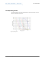
1
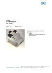
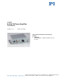
PZ250E E-836.1G Piezo Amplifier User Manual Version: 1.0.1 Date: 10.03.2014 This document describes the following product: E-836.1G Piezo Amplifier, 1 Channel, Bench-Top, -30 to 130 V Physik Instrumente (PI) GmbH & Co. KG · Auf der Römerstr. 1 76228 Karlsruhe, Germany Telephon +49 721 4846-0 · Telefax +49 721 4846-1019 · E-Mail [email protected] Physik Instrumente (PI) GmbH & Co. KG is the owner of the following trademarks: PI®, PIC®, PICMA®, Picoactuator®, PIFOC®, PILine®, PInano®, PiezoWalk®, NEXACT®, NEXLINE®, NanoCube®, NanoAutomation® © 2014 Physik Instrumente (PI) GmbH & Co. KG, Karlsruhe, Germany. The text, photographs and drawings in this manual are protected by copyright. With regard thereto, Physik Instrumente (PI) GmbH & Co. KG retains all the rights. Use of said text, photographs and drawings is permitted only in part and only upon citation of the source. Original instructions First printing: 10.03.2014 Document number: PZ250E, BRo, version 1.0.1 Subject to change without notice. This manual is superseded by any new release. The latest release is available for download (p. 3) on our website. Contents 1 About this Document 1.1 1.2 1.3 1.4 2 3 Goal and Target Audience of this User Manual ...................................................1 Symbols and Typographic Conventions ...............................................................1 Other Applicable Documents ................................................................................2 Downloading Manuals ..........................................................................................3 Safety 2.1 2.2 2.3 5 Intended Use ........................................................................................................5 General Safety Instructions ..................................................................................5 Organizational Measures ......................................................................................6 Product Description 3.1 3.2 1 7 Product View.........................................................................................................7 3.1.1 Front Panel .........................................................................................7 3.1.2 Rear Panel ..........................................................................................9 Scope of Delivery ...............................................................................................10 4 Unpacking 11 5 Installation 13 5.1 5.2 5.3 5.4 5.5 6 Start-Up 6.1 6.2 6.3 7 General Notes on Installation .............................................................................13 Connecting the E-836.1G to the Protective Earth Conductor ............................13 Connecting the Power Supply to the E-836.1G ..................................................14 Connecting the Stage .........................................................................................15 Connecting the Control Input Voltage ................................................................15 17 General Notes on Start-Up .................................................................................17 Switching on the E-836.1G .................................................................................18 Executing Motions ..............................................................................................19 Maintenance 7.1 7.2 21 General Notes on Maintenance ..........................................................................21 Cleaning the E-836.1G .......................................................................................21 8 Troubleshooting 23 9 Customer Service 25 10 Technical Data 27 10.1 10.2 10.3 10.4 10.5 Specifications......................................................................................................27 10.1.1 Data Table ........................................................................................27 10.1.2 Maximum Ratings .............................................................................28 10.1.3 Ambient Conditions and Classifications ...........................................28 Operating Limits .................................................................................................29 Dimensions .........................................................................................................30 Block Diagrams ..................................................................................................31 Pin Assignment ...................................................................................................31 10.5.1 PZT Socket .......................................................................................31 10.5.2 24 VDC Power Supply Connection...................................................31 11 Old Equipment Disposal 33 12 Appendix 35 12.1 12.2 Lifetime of PICMA® Actuators ............................................................................35 EC Declaration of Conformity .............................................................................39 1 About this Document 1 About this Document In this Chapter Goal and Target Audience of this User Manual ............................................................ 1 Symbols and Typographic Conventions ........................................................................ 1 Other Applicable Documents ......................................................................................... 2 Downloading Manuals ................................................................................................... 3 1.1 Goal and Target Audience of this User Manual This manual contains information on the intended use of the E-836.1G. It assumes that the reader has a fundamental understanding of basic servo systems as well as motion control concepts and applicable safety procedures. The latest versions of the user manuals are available for download (p. 3) on our website. 1.2 Symbols and Typographic Conventions The following symbols and typographic conventions are used in this user manual: DANGER Imminently hazardous situation If not avoided, the hazardous situation will result in death or serious injury. Actions to take to avoid the situation. NOTICE Dangerous situation If not avoided, the dangerous situation will result in damage to the equipment. Actions to take to avoid the situation. E-836.1G Piezo Amplifier PZ250E Version: 1.0.1 1 1 About this Document INFORMATION Information for easier handling, tricks, tips, etc. Symbol/ Label Meaning 1. Action consisting of several steps whose sequential order must be observed 2. Action consisting of one or several steps whose sequential order is irrelevant List item p. 5 Cross-reference to page 5 RS-232 Labeling of an operating element on the product (example: socket of the RS-232 interface) Warning signs affixed to the product that refer to detailed information in this manual. 1.3 Other Applicable Documents The devices and software tools which are mentioned in this documentation are described in their own manuals. The latest versions of the user manuals are available for download (p. 3) on our website. 2 Component Document Analog Controller LabView Driver Library PZ181E Software Manual Version: 1.0.1 PZ250E E-836.1G Piezo Amplifier 1 About this Document 1.4 Downloading Manuals INFORMATION If a manual is missing on our website or if there are problems in downloading: Contact our customer service department (p. 25). The current versions of the manuals are found on our website. For some products (e.g. Hexapod systems and electronics that are delivered with a CD), access to the manuals is password-protected. The password is stored on the CD. Download freely accessible manuals 1. Open the website http://www.pi-portal.ws. 2. Click Downloads. 3. Click the corresponding category (e.g. E Piezo Drivers & Nanopositioning Controllers) 4. Click the corresponding product code (e.g. E-836). 5. Click Documents. The available manuals are displayed. 6. Click the desired manual and save it on the hard disk of your PC or on a data storage medium. Download password-protected manuals 1. Carry out steps 1 to 5 of the download process for freely accessible manuals. 2. Insert the product CD in the PC drive. 3. Switch to the Manuals directory on the CD. 4. In the Manuals directory, open the Release News (file including releasenews in the file name). 5. Find the user name and password in the User login for software download section in the Release News. 6. In the User login area on the left margin in the website, enter the user name and the password in the corresponding fields. 7. Click Login. The available manuals are displayed. 8. Click the desired manual and save it on the hard disk of your PC or on a data storage medium. E-836.1G Piezo Amplifier PZ250E Version: 1.0.1 3 2 Safety 2 Safety In this Chapter Intended Use ................................................................................................................. 5 General Safety Instructions ........................................................................................... 5 Organizational Measures............................................................................................... 6 2.1 Intended Use The E-836.1G is a laboratory device as defined by DIN EN 61010-1. It is intended to be used in interior spaces and in an environment which is free of dirt, oil and lubricants. Corresponding to its design, the E-836.1G is intended for driving capacitive loads (e. g. piezo ceramic actuators). The E-836.1G must not be used for purposes other than those named in this user manual. In particular, the E-836.1G must not be used to drive ohmic or inductive loads. The E-836.1G can be used for static as well as dynamic applications. 2.2 General Safety Instructions The E-836.1G is built according to state-of-the-art technology and recognized safety standards. Improper use can result in personal injury and/or damage to the E-836.1G. Only use the E-836.1G for its intended purpose, and only use it if it is in a good working order. Read the user manual. Immediately eliminate any faults and malfunctions that are likely to affect safety. The operator is responsible for the correct installation and operation of the E-836.1G. E-836.1G Piezo Amplifier PZ250E Version: 1.0.1 5 2 Safety Install the E-836.1G near the power source so that the power plug can be quickly and easily disconnected from the mains. Use the supplied components (power supply, adapter and power cord) to connect the E-836.1G to the power source. If one of the supplied components for connecting to the power source has to be replaced, use a sufficiently dimensioned component. If a protective earth conductor is not or not properly connected, dangerous touch voltages can occur on the E-836.1G in the case of malfunction or failure of the system. If touch voltages exist, touching the E-836.1G can result in serious injury or death from electric shock. Connect the E-836.1G to a protective earth conductor (p. 13) before start-up. Do not remove the protective earth conductor during operation. If the protective earth conductor has to be removed temporarily (e. g. in the case of modifications), reconnect the E-836.1G to the protective earth conductor before starting it up again. 2.3 Organizational Measures User manual Always keep this user manual available by the E-836.1G. The latest versions of the user manuals are available for download (p. 3) on our website. Add all information given by the manufacturer to the user manual, for example supplements or Technical Notes. If you pass the E-836.1G on to other users, also turn over this user manual as well as all other relevant information provided by the manufacturer. Only use the device on the basis of the complete user manual. If your user manual is incomplete and is therefore missing important information, serious or fatal injury as well as property damage can result. Only install and operate the E-836.1G after having read and understood this user manual. Personnel qualification Only authorized and qualified personnel must install, operate, maintain and clean the E-836.1G. 6 Version: 1.0.1 PZ250E E-836.1G Piezo Amplifier 3 Product Description 3 Product Description In this Chapter Product View ................................................................................................................. 7 Scope of Delivery ........................................................................................................ 10 3.1 Product View 3.1.1 Front Panel Figure 1: E-836.1G piezo amplifier, front view Labeling Type Function 24 VDC Barrel connector socket (input) Connection for the supply voltage Threaded bolt with fastening material for protective earth conductor Protective earth connection (p. 13) BNC socket Connection of a signal source Control In The threaded bolt must be connected to a protective earth conductor, since the E836.1G is not grounded via the power supply connector. E-836.1G Piezo Amplifier PZ250E Input for the control input voltage of the E-836.1G Version: 1.0.1 7 3 Product Description Labeling Type Function PZT Connection of the stage -30 to 130 V LEMO socket EPK.00.250.NTN DC Offset Rotary knob 1-turn potentiometer, adds 0 to 10 V to control input voltage Power LED Display of the ready state: green/off E-836 Piezo Driver 8 Version: 1.0.1 Output of the piezo voltage for the piezo actuator in the stage Green: E-836.1G is ready for operation Off: E-836.1G is not ready for operation - Manufacturer's logo - Product Description - CE conformity mark PZ250E E-836.1G Piezo Amplifier 3 Product Description 3.1.2 Rear Panel Figure 2: E-836.1G piezo amplifier, rear view Labeling Function Data matrix code (example; contains the serial number) E-836.1G Product name Manufacturer's logo 113064443 Serial number (example), individual for each E-836.1G Meaning of the places (counting from left): 1 = internal information, 2 and 3 = manufacturing year, 4 to 9 = consecutive numbers Country of origin: Germany Country of origin Warning sign "Observe manual!" Old equipment disposal (p. 33) CE conformity mark WWW.PI.WS E-836.1G Piezo Amplifier Manufacturer's address (website) PZ250E Version: 1.0.1 9 3 Product Description 3.2 Scope of Delivery 10 Item ID Components E-836.1G Piezo amplifier C-663.PS Separate 24 V wide-range-input power supply for use with line voltages from 100 to 240 VAC and voltage frequencies of 50 or 60 Hz, with barrel connector 3763 Power cord PZ250E User manual for E-836.1G (this document) E500T0011 Technical note for the LabVIEW analog driver Version: 1.0.1 PZ250E E-836.1G Piezo Amplifier 4 Unpacking 4 Unpacking 1. Unpack the E-836.1G with care. 2. Compare the contents against the items covered by the contract and against the packing list. 3. Inspect the contents for signs of damage. If parts are missing or you notice signs of damage, contact PI immediately. 4. Keep all packaging materials in case the product needs to be returned. E-836.1G Piezo Amplifier PZ250E Version: 1.0.1 11 5 Installation 5 Installation In this Chapter General Notes on Installation ...................................................................................... 13 Connecting the E-836.1G to the Protective Earth Conductor ..................................... 13 Connecting the Power Supply to the E-836.1G........................................................... 14 Connecting the Stage .................................................................................................. 15 Connecting the Control Input Voltage ......................................................................... 15 5.1 General Notes on Installation Install the E-836.1G near the power source so that the power plug can be quickly and easily disconnected from the mains. Only use cables and connections that meet local safety regulations. 5.2 Connecting the E-836.1G to the Protective Earth Conductor INFORMATION Observe the applicable standards for mounting the protective earth conductor. Prerequisite You have read and understood the general notes on installation (p. 13). The E-836.1G is switched off, i. e. the power supply is not connected to the power socket via the power cord. Tools and accessories Suitable protective earth conductor: − Cable cross-section ≥0.75 mm − Contact resistance < 0.1 ohm at 25 A at all connection points relevant for mounting the protective earth conductor E-836.1G Piezo Amplifier PZ250E 2 Version: 1.0.1 13 5 Installation Fastening material for the protective earth conductor, sits on the protective earth connector (threaded bolt) in the following order upon delivery of the E836.1G, starting from the case: − Safety washer − Nut − Flat washer − Toothed washer − Nut Suitable wrench Connecting the E-836.1G to the protective earth conductor 1. If necessary, fasten a suitable cable lug to the protective earth conductor. 2. Remove the outer nut from the protective earth connection on the front panel of the E-836.1G (threaded bolt (p. 7) marked with ). 3. Connect the protective earth conductor: a) b) c) Push the cable lug of the protective earth conductor onto the threaded bolt. Screw the nut onto the threaded bolt. In this way, the cable lug of the protective earth conductor is wedged between the toothed washer and the nut. Tighten the nut with at least three rotations and a torque of 1.2 Nm to 1.5 Nm. 5.3 Connecting the Power Supply to the E-836.1G Prerequisites The power cord is not connected to the power socket. Tools and accessories Included 24 V wide-range-input power supply (for line voltages between 100 and 240 VAC at 50 or 60 Hz) Alternatively: Sufficiently dimensioned power supply Included power cord Alternatively: Sufficiently dimensioned power cord Connecting the power supply to the E-836.1G Connect the power supply to the 24 VDC connection of the E-836.1G. 14 Version: 1.0.1 PZ250E E-836.1G Piezo Amplifier 5 Installation 5.4 Connecting the Stage Prerequisite When a signal source is connected to the Control In BNC socket: The signal source is switched off or its output is 0 V. The DC Offset potentiometer is turned fully counterclockwise. Tools and accessories Stage with the following characteristics: − Drive: Piezo actuator(s) − Operating voltage range: -30 to 130 V − Voltage connection: Via LEMO connector Connecting the stage Connect the voltage connection of the stage to the PZT -30 to 130 V LEMO socket of the E-836.1G. 5.5 Connecting the Control Input Voltage INFORMATION The control signal for the output piezo voltage is the sum of the following signals: Control input voltage at the Control In BNC socket Offset that is set with the DC Offset potentiometer The control signal should always be within the range of –2 to +12 V. The range can be expanded to –3 to +13 V. However, this can shorten the lifetime of the piezo actuator in the stage (p. 35). Prerequisite The signal source for the control input voltage is switched off or its output is 0 V. The DC Offset potentiometer is turned fully counterclockwise. E-836.1G Piezo Amplifier PZ250E Version: 1.0.1 15 5 Installation Tools and accessories Signal source for the control input voltage. The control input voltage can also be a computer-generated analog signal (e. g. from a data acquisition board). You can use the PI LabVIEW analog drivers to generate the analog signal (see E500T0011 Technical Note and the PZ181E manual). Connecting the control input voltage Connect the signal source to the Control In BNC socket. 16 Version: 1.0.1 PZ250E E-836.1G Piezo Amplifier 6 Start-Up 6 Start-Up In this Chapter General Notes on Start-Up .......................................................................................... 17 Switching on the E-836.1G .......................................................................................... 18 Executing Motions ....................................................................................................... 19 6.1 General Notes on Start-Up DANGER Risk of electric shock if the protective earth conductor is not connected! If a protective earth conductor is not or not properly connected, dangerous touch voltages can occur on the E-836.1G in the case of malfunction or failure of the system. If touch voltages exist, touching the E-836.1G can result in serious injury or death from electric shock. Connect the E-836.1G to a protective earth conductor (p. 13) before start-up. Do not remove the protective earth conductor during operation. If the protective earth conductor has to be removed temporarily (e. g. in the case of modifications), reconnect the E-836.1G to the protective earth conductor before starting it up again. NOTICE Reduced lifetime of the piezo ceramic due to permanently high voltage! The permanent application of a high static voltage to the piezo actuators in the stage reduces the lifetime of the piezo ceramic. If the E-836.1G is not used, but is to remain switched on: Set the control signal (sum of Control In and DC Offset) to 0 V. E-836.1G Piezo Amplifier PZ250E Version: 1.0.1 17 6 Start-Up INFORMATION The output piezo voltage contains the switching frequency of the internal DC/DC transducer of the E-836.1G (600 kHz). This frequency has no effect on the motion of the stage, however. For this reason, the measurement of the piezo voltage (e.g. with a digital oscilloscope) is not suitable for determining the motion resolution of the stage. Measure the motion of the stage directly, e.g. with optical methods or highresolution sensors. INFORMATION When it is switched off, the E-836.1G generates a voltage spike at the output for the piezo voltage. A connected stage will execute a corresponding motion, which can be noticeable as a clicking sound. This behavior is unproblematic and does not affect the stage. 6.2 Switching on the E-836.1G Prerequisite You have read and understood the general notes on start-up (p. 17). You have connected the power supply to the E-836.1G (p. 14). When a signal source is connected to the Control In BNC socket: The signal source is switched off or its output is 0 V. The DC Offset potentiometer is turned fully counterclockwise. Switching on the E-836.1G Connect the power cord of the power supply with the power socket. The Power LED on the front panel shows the ready state of the E-836.1G: 18 − Green: E-836.1G is ready for operation − Off: E-836.1G is not ready for operation Version: 1.0.1 PZ250E E-836.1G Piezo Amplifier 6 Start-Up 6.3 Executing Motions INFORMATION The control signal for the output piezo voltage is the sum of the following signals: Control input voltage at the Control In BNC socket Offset that is set with the DC Offset potentiometer The control signal should always be within the range of –2 to +12 V. The range can be expanded to –3 to +13 V. However, this can shorten the lifetime of the piezo actuator in the stage (p. 35). Prerequisite You have read and understood the user manual of the stage. You have mounted the stage according to the description in the corresponding user manual. You have connected the stage to the E-836.1G (p. 15). When the stage is operated via a control input voltage: You have connected a signal source to the E-836.1G (p. 15). You have switched on the E-836.1G (p. 18). Executing motions Change the control signal within the range of -2 V to +12 V: − Change the control input voltage at the Control In BNC socket. − Turn the DC Offset potentiometer. The stage generates corresponding motions. E-836.1G Piezo Amplifier PZ250E Version: 1.0.1 19 7 Maintenance 7 Maintenance In this Chapter General Notes on Maintenance ................................................................................... 21 Cleaning the E-836.1G ................................................................................................ 21 7.1 General Notes on Maintenance The E-836.1G is maintenance-free. 7.2 Cleaning the E-836.1G NOTICE Short circuits or flashovers! The E-836.1G contains electrostatic sensitive devices that can be damaged by short circuits or flashovers when cleaning fluids enter the case. Before cleaning, remove the E-836.1G from the power source by pulling the power plug. Prevent cleaning fluid from entering the case. When necessary, clean the surfaces of the E-836.1G case with a cloth that has been lightly dampened with a mild cleanser or disinfectant. Do not use any organic solvents. E-836.1G Piezo Amplifier PZ250E Version: 1.0.1 21 8 Troubleshooting 8 Troubleshooting Problem Possible Causes Solution Stage does not move Cable is not connected correctly Check the cable connections. Stage or stage cable is defective Replace the defective stage with a suitable stage and test the new combination. Control signal exceeds the permissible range Check the control input voltage (Control In BNC socket) and the setting of the DC Offset potentiometer. If you generate the control input voltage with a data acquisition board using the LabVIEW analog drivers: E-836.1G voltage output is deactivated Check that the analog drivers and the data acquisition board are working correctly. When the internal temperature reaches ≥85° C the E836.1G voltage output is deactivated and the stage stops moving. When the internal temperature then drops to 75° C, the voltage output is switched on again automatically. Ensure sufficient ventilation at the place of installation. Reduce the frequency and/or the amplitude and/or the output duration of the control input voltage (Control In BNC socket). If the problem that occurred with your system is not listed in the table above or cannot be solved as described, contact our customer service department (p. 25). E-836.1G Piezo Amplifier PZ250E Version: 1.0.1 23 9 Customer Service 9 Customer Service For inquiries and orders, contact your PI sales engineer or send us an e-mail (mailto:[email protected]). If you have questions concerning your system, have the following information ready: Product codes and serial numbers of all products in the system Firmware version of the controller (if present) Version of the driver or the software (if present) Operating system on the PC (if present) The latest versions of the user manuals are available for download (p. 3) on our website. E-836.1G Piezo Amplifier PZ250E Version: 1.0.1 25 10 Technical Data 10 Technical Data In this Chapter Specifications .............................................................................................................. 27 Operating Limits .......................................................................................................... 29 Dimensions .................................................................................................................. 30 Block Diagrams ........................................................................................................... 31 Pin Assignment ............................................................................................................ 31 10.1 Specifications 10.1.1 Data Table E-836.1G Function Unit Piezo amplifier, 1 channel Bench-top device Control input voltage -2 to 12 V Output voltage -30 to 130 V Peak current (<8 ms) 100 mA Average current 50 mA Current limitation Short-circuit-proof Voltage gain 10 ±0.1 Ripple, noise, 0 to 100 kHz 0.8 mVrms Capacitive base load (internal) 10 nF Output impedance 5 Ω Input impedance 1 MΩ Connectors BNC, LEMO Barrel connector (power supply) 1-turn pot., adds 0 to 10 V to Control input Operating temperature range 5 to 50 °C Overtemp protection Deactivation at 85 °C °C Operating voltage 24 ±10 %, included: external power supply, 24 V / 2.0 A VDC Power consumption (max.) 16 W Current consumption (max.) 0.65 A Ask about custom designs! E-836.1G Piezo Amplifier PZ250E Version: 1.0.1 27 10 Technical Data 10.1.2 Maximum Ratings The E-836.1G is designed for the following operating data: Input on: Maximum Operating Voltage Barrel connector socket 24 V Operating Frequency Fused Current Consumption 2A 10.1.3 Ambient Conditions and Classifications The following ambient conditions and classifications must be observed for the E836.1G: Area of application For indoor use only Maximum altitude 2000 m Relative humidity Highest relative humidity 80% for temperatures up to 31°C Decreasing linearly to 50% relative humidity at 40°C 28 Storage temperature 0°C to 70°C Transport temperature –25°C to +85°C Overvoltage category II Protection class I Degree of pollution 2 Measurement category I Degree of protection according to IEC 60529 IP20 Version: 1.0.1 PZ250E E-836.1G Piezo Amplifier 10 Technical Data 10.2 Operating Limits The following diagram shows the operating limits for various piezo loads. The curve values are capacitance values in μF. Figure 3: Operating limits E-836.1G Piezo Amplifier PZ250E Version: 1.0.1 29 10 Technical Data 10.3 Dimensions Dimensions in mm. Note that the decimal places are separated by a comma in the drawings. Figure 4: E-836.1G, dimensions in mm 30 Version: 1.0.1 PZ250E E-836.1G Piezo Amplifier 10 Technical Data 10.4 Block Diagrams Figure 5: E-836.1G block diagram 10.5 Pin Assignment 10.5.1 PZT Socket LEMO socket EPK.00.250.NTN, 2-pin, for transmission of the piezo voltage: Outer contact: PZT ground (connected with the case) Inner contact: PZT+ (–30 to +130 V) 10.5.2 24 VDC Power Supply Connection Barrel connector socket Pin Function Center pin Input: 24 V DC Outer conductor GND (power) E-836.1G Piezo Amplifier PZ250E Version: 1.0.1 31 11 Old Equipment Disposal 11 Old Equipment Disposal In accordance with the applicable EU law, electrical and electronic equipment may not be disposed of with unsorted municipal wastes in the member states of the EU. When disposing of your old equipment, observe the international, national and local rules and regulations. To meet the manufacturer’s product responsibility with regard to this product, Physik Instrumente (PI) GmbH & Co. KG ensures environmentally correct disposal of old PI equipment that was first put into circulation after 13 August 2005, free of charge. If you have old PI equipment, you can send it postage-free to the following address: Physik Instrumente (PI) GmbH & Co. KG Auf der Römerstr. 1 D-76228 Karlsruhe, Germany E-836.1G Piezo Amplifier PZ250E Version: 1.0.1 33 12 Appendix 12 Appendix In this Chapter Lifetime of PICMA® Actuators ..................................................................................... 35 EC Declaration of Conformity ...................................................................................... 39 12.1 Lifetime of PICMA® Actuators The lifetime of a PICMA® piezo actuator can be influenced by the following factors: Applied voltage Temperature Relative humidity The following diagrams show how the individual factors influence the lifetime of the actuator. Figure 6: Dependency of the mean time between failure (MTTF) of a PICMA® actuator on the applied voltage E-836.1G Piezo Amplifier PZ250E Version: 1.0.1 35 12 Appendix Figure 7: Dependency of the mean time between failure (MTTF) of a PICMA® actuator on the ambient temperature Figure 8: Dependency of the mean time between failure (MTTF) of a PICMA® actuator on the relative humidity 36 Version: 1.0.1 PZ250E E-836.1G Piezo Amplifier 12 Appendix The calculated lifetime in hours results from the product of the values for the individual contributions: MTTF = AU × AT × AF AU: Contribution of the applied voltage AT: Contribution of the ambient temperature AF: Contribution of the relative humidity The contribution of the applied voltage is especially important for applications. The lifetime increases exponentially with decreasing voltage. The recommended maximum range for the input voltage of the E-836.1G is therefore –2 to +12 V. This results in a piezo voltage range of –20 to 120 V (in open-loop operation). The input voltage range can be expanded from –3 to +13 V (the piezo voltage is then in the range of -30 to +130 V), which however reduces the lifetime of the actuator. Example (see markings in the diagrams) Applied voltage: 100 V DC ⇒ AU = 75 Ambient temperature: 45 °C ⇒ AU = 100 Relative humidity: 75 % ⇒ AF = 14 MTTF = 14 × 75 × 100 h = 105000 h (approx. 12 years) You can find details in the PI catalog under "Reliability of PICMA® Multilayer Actuators". E-836.1G Piezo Amplifier PZ250E Version: 1.0.1 37 12 Appendix 12.2 EC Declaration of Conformity For the E-836.1G, an EC Declaration of Conformity has been issued in accordance with the following European directives: 2006/95/EC, Low Voltage Directive 2004/108/EC, EMC Directive 2011/65/EU, RoHS Directive The applied standards certifying the conformity are listed below. Safety (Low Voltage Directive): EN 61010-1:2010 EMC: EN 61326-1:2013 RoHS: EN 50581:2012 E-836.1G Piezo Amplifier PZ250E Version: 1.0.1 39