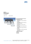
1
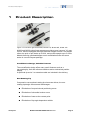
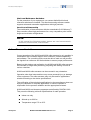
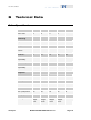
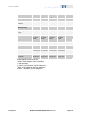
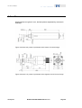
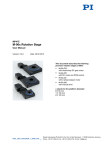
MP86E User Manual
M-228 and M-229 Stepper-Mike Linear
Actuators
Release: 1.1.0 Date: 2009-11-05
This document describes the following
products:
■
M-228.10S
Stepper-Mike Linear Actuator, 10 mm, Stepper
Motor, Gearhead, Limit Switches
■
M-228.11S
Stepper-Mike Linear Actuator, 10 mm, Stepper
Motor, Direct Drive, Limit Switches
■
M-229.25S
Stepper-Mike Linear Actuator, 25 mm, Stepper
Motor, Gearhead, Limit Switches
■
M-229.26S
Stepper-Mike Linear Actuator, 25 mm, Stepper
Motor, Direct Drive, Limit Switches
© Physik Instrumente (PI) GmbH & Co. KG
Auf der Römerstr. 1 ⋅ 76228 Karlsruhe, Germany
Tel. +49 721 4846-0 ⋅ Fax: +49 721 4846-299
[email protected] ⋅ www.pi.ws
Physik Instrumente (PI) GmbH & Co. KG is the owner of the following company names and trademarks:
PI®, PIC®, PICMA®, PILine®, PIFOC®, PiezoWalk®, NEXACT®, NEXLINE®, NanoCube®,
NanoAutomation®
The following designations are protected company names or registered trademarks of third parties:
Microsoft, Windows, LabView
© 2009 by Physik Instrumente (PI) GmbH & Co. KG, Karlsruhe, Germany.
The text, photographs and drawings in this manual enjoy copyright protection. With regard thereto,
Physik Instrumente (PI) GmbH & Co. KG reserves all rights. Use of said text, photographs and drawings
is permitted only in part and only upon citation of the source.
First printing 05.11.2009
Document Number MP86E, NPa, Release 1.1.0
M-228_M-229_User_MP86E110.doc
Subject to change without notice. This manual is superseded by any new release. The newest release is
available for download at www.pi.ws (http://www.pi.ws).
About This Document
Users of this Manual
This manual is designed to help the reader to install and operate the M-228 and M-229 Stepper-Mike
Linear Actuators. It is assumed that the reader has a fundamental understanding of motion control
concepts and applicable safety procedures.
The manual describes the physical specifications and dimensions of the M-228 and M-229 Stepper-Mike
Linear Actuators as well as the procedures which are required to put the associated motion system into
operation.
The latest version is available for download at www.pi.ws. Please direct any inquiry to your
PI representative or write [email protected].
Conventions
The notes and symbols used in this manual have the following meanings:
WARNING
Calls attention to a procedure, practice or condition which, if not
correctly performed or adhered to, could result in injury or death.
CAUTION
Calls attention to a procedure, practice, or condition which, if not
correctly performed or adhered to, could result in damage to
equipment.
NOTE
Provides additional information or application hints.
Related Documents
The motion controller and the software tools which might be mentioned in this documentation are
described in their own manuals. All documents are available as PDF files via download from the PI
Website (www.pi.ws (http://www.pi.ws)). For updated releases contact your PI representative or write
[email protected] (mailto:[email protected]).
!
Contents
1
Product Description
1.1
1.2
1.3
1.4
1.5
1.6
2
3
12
Limit Switches ................................................................................... 12
Reference Switch .............................................................................. 13
Troubleshooting
4.1
4.2
8
Mechanical Mounting .......................................................................... 8
Startup............................................................................................... 10
Special Hardware Information
3.1
3.2
4
Prescribed Use.................................................................................... 3
Safety Instructions............................................................................... 4
Model Survey ...................................................................................... 6
Contents of Delivery ............................................................................ 6
Controller............................................................................................. 7
Additional Components ....................................................................... 7
Start-Up
2.1
2.2
2
14
Customer Service.............................................................................. 14
What if ... ........................................................................................... 14
5
Maintenance
17
6
Technical Data
18
6.1
6.2
6.3
Specifications .................................................................................... 18
Dimensions........................................................................................ 20
Pin Assignment ................................................................................. 22
7
Old Equipment Disposal
23
8
Glossary of Terms
24
Product Description
1
Product Description
Figure 1: From left to right: M-229.26S, M-228.11S, M-229.25S, M-228.10S
M-228 and M-229 series linear actuators provide a travel range of 10, resp.
25 mm, and are equipped with high-resolution stepper motors. The stepper
mikes can push or pull loads up to 80 N, and provide speeds up to 5 mm/s.
Models featuring gearhead/stepper motor combinations offer the same
stroke in a more compact package.
Cost-Effective Design, Valuable Features
The cost-effective design offers many useful features such as a
non-rotating tip, limit and reference switches and a mechanical position
display.
A spherical tip and a 3 m extension cable are included in the delivery.
Non-Rotating Tip
Compared to conventional rotating-tip micrometer drives, the nonrotating-tip design offers several advantages:
www.pi.ws
■
Elimination of torque-induced positioning errors
■
Elimination of sinusoidal motion errors
■
Elimination of wear at the contact point
■
Elimination of tip-angle-dependent wobble
M-228 and M-229 MP86E Release 1.1.0
Page 2
Product Description
Limit and Reference Switches
For the protection of your equipment, non-contact Hall-effect limit and
reference switches are installed. The direction-sensing reference switch
supports advanced automation applications with high precision.
Low Cost of Ownership
The combination of these actuators with the networkable C-663 Mercury™
Step controller offers high performance for a very competitive price in both
single and multi-axis configurations.
NOTE
In this manual the following product names are used synonymously:
positioner, linear actuator, mike actuator.
1.1
Prescribed Use
Correct operation of the M-228 and M-229 mike actuators is only possible in
combination with a suitable stepper motor controller (ordered separately)
and software. The controlling device must be able to read out and process
the signals from reference and limit switches to ensure proper performance.
Based on their design and realization, the M-228 and M-229 mike actuators
are intended for single-axis positioning, adjusting and shifting of loads at
various velocities.
M-228 and M-229 mike actuators can be mounted in any orientation.
Operation other than instructed here may cause personal injury or damage
of the equipment. The mike actuators may only be used for applications
suitable according to the device specifications.
The verification of the technical specifications by the manufacturer does not
imply the validation of complete applications. In fact the operator is
responsible for the process validation and the appropriate releases.
M-228 and M-229 are laboratory apparatus as defined by DIN EN 61010.
They meet the following minimum specifications for safe operation:
www.pi.ws
■
Indoor use only
■
Altitude up to 2000 m
■
Temperature range 5°C to 40°C
M-228 and M-229 MP86E Release 1.1.0
Page 3
Product Description
■
Max. relative humidity 80% for temperatures up to 31°C, decreasing
linearly to 50% relative humidity at 40°C
■
Line voltage fluctuations not greater than ±10% of the line voltage
■
Transient overvoltages as typical for public power supply
Note: The nominal level of the transient overvoltage is the standing
surge voltage according to the overvoltage category II (IEC 60364-4443).
■
Degree of pollution: 2
These data are no limitations for the specifications in the technical data
table (p. 18).
1.2
Safety Instructions
Install and operate the Stepper-Mike Linear Actuator only when you have
read the operating instruction. Always keep the user manual safe and close
to the described device. If the user manual is lost or damaged, contact your
PI representative for a new copy or download it from the PI homepage
(http://www.pi.ws). Also keep and add all further information (e.g. extended
instructions or Technical Notes) to the User Manual.
Read carefully the user manuals of all other components involved such as
controllers or software.
WARNING—CRUSH HAZARD
Ensure that no body parts and no objects can be trapped by the
moving tip or any object connected to it.
CAUTION
When you connect the mike actuator to the controller, be aware that
the mike actuator could perform an undesired move.
CAUTION
Connect a stepper motor mike actuator only to a suitable stepper motor
controller.
Otherwise the controller could be damaged.
www.pi.ws
M-228 and M-229 MP86E Release 1.1.0
Page 4
!
!
Product Description
!
CAUTION
!
CAUTION
!
CAUTION
!
CAUTION
!
CAUTION
During operation the Stepper-Mike Linear Actuator produces heat
which might disturb your application.
During mounting or operation of the mike actuator, ensure that the
cables are not bend too much or the cable could break.
Avoid lateral forces at the tip of the mike actuator. The guiding
accuracy can be reduced or the mike actuator can be damaged.
Ensure that the mike actuator is mounted correctly before startup.
A crash at the end stop can damage the mechanics, especially at high
velocity.
Do not disable limit switch processing on the controller.
Be aware that the function to stop automatically at the limit switch may
not be supported by the controller.
Check limit switch operation at about 10 or 20% of the maximum
velocity.
www.pi.ws
M-228 and M-229 MP86E Release 1.1.0
Page 5
Product Description
1.3
Model Survey
The following standard configurations of M-228 and M-229 mike actuators
are available:
M-228.10S
M-228.11S
M-229.25S
M-229.26S
Stepper-Mike Linear Actuator, 10 mm, Stepper Motor,
Gearhead, Limit Switches
Stepper-Mike Linear Actuator, 10 mm, Stepper Motor,
Direct Drive, Limit Switches
Stepper-Mike Linear Actuator, 25 mm, Stepper Motor,
Gearhead, Limit Switches
Stepper-Mike Linear Actuator, 25 mm, Stepper Motor,
Direct Drive, Limit Switches
Figure 2: From left to right: M-229.26S, M-228.11S, M-229.25S, M-228.10S
1.4
Contents of Delivery
Unpack the Stepper-Mike Linear Actuator with care. Compare the contents
against the items covered by the order and against the packing list.
The following components are included:
www.pi.ws
■
M-228 or M-229 Stepper-Mike Linear Actuator according to the order
■
C-815.38 extension cable for the connection to the controller, Sub-D
connector 15-pin, 3 m cable
■
M23010117 spherical tip
Furthermore, a flat tip comes with the M-228.10S and the M-229.25S.
■
MP86 User manual for M-228 and M-229 (this document) in printed
form
M-228 and M-229 MP86E Release 1.1.0
Page 6
Product Description
If parts are missing or you notice signs of damage, contact your PI
representative or write to [email protected] immediately.
Save all packing materials in case the product needs to be shipped again.
1.5
Controller
A controller is necessary for each mike actuator.
CAUTION
!
Connect a stepper motor mike actuator only to a suitable stepper motor
controller.
Otherwise the controller could be damaged.
Use only controllers which are able to process limit switch signals.
For best performance and system compatibility we recommend using
PI controllers.
Contact your PI representative or write to [email protected] if you want to order
the following controller:
Order Number
C-663.10
1.6
Description
Mercury™ Step Stepper Motor Controller,
1 Channel, with Wide-Range Power Supply (24V),
single-axis
Additional Components
Contact your PI representative or write an e-mail to [email protected] if you need
the following additional components:
Order Number
M23010116
www.pi.ws
Description
Flat tip
M-228 and M-229 MP86E Release 1.1.0
Page 7
Start-Up
2
Start-Up
2.1
Mechanical Mounting
CAUTION
During mounting or operation of the mike actuator, ensure that the
cables are not bend too much or the cable could break.
CAUTION
Avoid lateral forces at the tip of the mike actuator. The guiding
accuracy can be reduced or the mike actuator can be damaged.
Figure 3: M-228, M-229 components of mechanics
1
2
3
4
5
www.pi.ws
Only with M-228.11S and M-229.26S: separate motor with
(a) Handwheel for moving the pusher manually
(with M-228.10S and M-229.25S the motor is integrated into the shaft)
Shaft
Mounting shaft with
(b) Clamping width: 6 mm
(c) Diameter:
Ø 9.5 mm with M-228.10S and M-228.11S
Ø 12 mm with M-229.25S and M-229.26S
Mounting nut
Pusher, non-rotating, with
(d) Threaded hole for mounting the tip
M-228 and M-229 MP86E Release 1.1.0
Page 8
!
!
Start-Up
Preparation:
Provide your application with a suitable mounting for the mounting shaft of
the mike actuator.
Refer to the figure of the mechanics components for the mounting shaft
dimensions.
Mounting:
1
Loosen the mounting nut from the mounting shaft of the mike
actuator, see figure of the mechanics components.
2
Position the mike actuator in the mounting of your application.
3
Fasten the mounting nut to clamp the mike actuator. A torque of
15 Nm is sufficient.
Changing the tips:
■
Affix the tip to the mike actuator with an open-end wrench SW5. We
recommend using a defined torque of 2 Nm for fixation.
M-228.10S and M-229.25S come with the flat tip already mounted.
M-228.11S and M-229.26S have no tip mounted.
On delivery, the spherical tip is included with all mike actuators.
www.pi.ws
M-228 and M-229 MP86E Release 1.1.0
Page 9
Start-Up
2.2
Startup
WARNING—CRUSH HAZARD
Ensure that no body parts and no objects can be trapped by the
moving tip or any object connected to it.
CAUTION
A crash at the end stop can damage the mechanics, especially at high
velocity.
!
Do not disable limit switch processing on the controller.
Be aware that the function to stop automatically at the limit switch may
not be supported by the controller.
Check limit switch operation at about 10 or 20% of the maximum
velocity.
CAUTION
When you connect the mike actuator to the controller, be aware that
the mike actuator could perform an undesired move.
CAUTION
!
Ensure that the mike actuator is mounted correctly before startup.
NOTE
The mike actuator comes with an extension cable. You can connect
this extension cable between the controller and the mike actuator.
Prior to operation, read the documentation for the controller.
If you use the C-663 Mercury™ Step stepper motor controller, proceed as
described in "Starting Operation" Section of the C-663 User Manual
(MS138).
www.pi.ws
M-228 and M-229 MP86E Release 1.1.0
!
Page 10
Start-Up
The following list contains steps which you should generally perform for the
startup.
1
If you are going to use a host computer, install the host software on
the host computer.
2
If it is necessary, connect the controller to the host computer.
3
Connect the mike to the controller. With multi-axis systems, we
recommend to note the axis assignment of the connection.
4
Switch on the controller.
5
Command a few test moves to make sure everything is working
properly.
NOTE
If you command a velocity which is higher than the specified maximum
velocity of the mechanics, then the motor will stall. Although no
movement is performed any more, the controller still keeps on counting
steps.
As stepper motors do not have position encoders, the position counter
will continue to increment. The controller's motor position may not
correspond with the actual motor position and this might endanger your
application.
The maximum velocity depends on various influences like operating
voltage, phase current setting and mechanical load. Datasheet values
are for orientation only and may not work in all applications. Note that
the C-663 uses microsteps which are 1/16 the size of the full steps
given in the hardware datasheets (1 full step = 16 microsteps).
Command test moves to check out the maximum possible velocity for
your individual application!
If it should be necessary to set stage-dependent parameters, you can use
the following values:
Mike Actuator
M-228.10S M-229.25S
Parameters
9*
9*
Max. acceleration
250
1000
Recommended
motor current
250
1000
Max. motor
current
* determined with C-663 stepper motor controller
www.pi.ws
M-228.11S and
M-229.26S
15*
600
mm/s2
mA
850
mA
M-228 and M-229 MP86E Release 1.1.0
Units
Page 11
Special Hardware Information
3
Special Hardware Information
3.1
Limit Switches
All M-228 and M-229 linear actuators are equipped with non-contact, Halleffect limit switches.
Each limit switch sends an overtravel signal on its own dedicated line to the
controller. Limit switch outputs are active low.
It is the controller that is responsible for stopping the motion. If it does not
do so in time, the axis will run into the end stop.
CAUTION
A crash at the end stop can damage the mechanics, especially at high
velocity.
Do not disable limit switch processing on the controller.
Be aware that the function to stop automatically at the limit switch may
not be supported by the controller.
Check limit switch operation at about 10 or 20% of the maximum
velocity.
Limit Switch Specifications:
www.pi.ws
Type:
magnetic sensor
Supply voltage
+5 V / GND, supplied by the motor connector
Signal output:
TTL level
Sink/source capability
20 mA at 18 °C
Signal logic:
normal motor operation: high; overtravel: low (i.e. active-low; signal
level changes from +5 V to 0 V when the switch is passed)
M-228 and M-229 MP86E Release 1.1.0
Page 12
!
Special Hardware Information
3.2
Reference Switch
The M-228 and M-229 Stepper-Mike Linear Actuators are equipped with
direction-sensing reference switches, which are located at about the
midpoint of the travel range. These sensors provide a TTL signal indicating
whether the mechanics is to the positive or negative side of a fixed point.
The rising or falling edge of this signal can be used as to indicate a known
reference position within 0.5 µm accuracy (depending on the controller).
The difference in the reference points when approached from the positive or
the negative side is about 0.2 mm to 0.4 mm.
See the controller user manual and/or associated software manuals for the
commands which make use of the reference signal.
NOTE
It is recommended to approach the reference point always from the
same direction to obtain best position repeatability.
www.pi.ws
M-228 and M-229 MP86E Release 1.1.0
Page 13
Troubleshooting
4
Troubleshooting
4.1
Customer Service
Call your PI representative or write to [email protected]; please have the following
information about your system ready:
4.2
■
Product codes and serial numbers of all products in the system
■
Current firmware version of the controller (if present)
■
Version of drivers and / or host software (if present)
■
Operating system on host PC (if present)
What if ...
The following information refers to a C-663.10 controller. If you use a
different controller, refer to the instructions in its manual.
The Mechanics Does Not Move
Cables not connected properly:
■ Check the connecting cables.
The axis is not referenced:
■ Reference the axis as described in controller and user manuals.
Incorrect configuration:
■ Check the parameter settings of the controller (SPA? in the GCS
command set, refer to the controller and the software manuals).
Wrong command or wrong syntax:
■ Check the error code (with PI-GCS command set, use ERR?; see
controller and software manuals for the error code explanations).
Wrong axis commanded:
■ Check if commanded axis is that of the desired mechanics.
www.pi.ws
M-228 and M-229 MP86E Release 1.1.0
Page 14
Troubleshooting
Mechanics or its cable is defective:
■ Replace mechanics with a working mechanics of the same type to
test a new combination of controller and mechanics (mechanics of a
different type may malfunction due to unsuitable parameter settings
on the controller).
■
Test cable and / or replace with a working cable of the same type.
The Mechanics Does Not Move, But Creates Noise
Values for velocity, acceleration and / or load are too high:
■ Reduce the velocity.
If you command a velocity which is higher than the specified
maximum velocity of the mechanics, then the motor will stall.
Although no movement is performed any more, the controller still
keeps on counting steps.
As stepper motors do not have position encoders, the position
counter will continue to increment. The controller's motor position
may not correspond with the actual motor position and this might
endanger your application.
The maximum velocity depends on various influences like operating
voltage, phase current setting and mechanical load. Datasheet
values are for orientation only and may not work in all applications.
Note that the C-663 uses microsteps which are 1/16 the size of the
full steps given in the hardware datasheets (1 full step =
16 microsteps).
Command test moves to check out the maximum possible velocity for
your individual application!
■
Reduce the acceleration.
■
Reduce the load on the mechanics.
The Mechanics Did Not Stop in Time and Ran into a Hard Stop
The velocity is too high, see also "Limit Switches" (p. 12), the limit switch is
out of order or the controller ignores the limit switch signal:
■
www.pi.ws
Stop the motor. Command the mechanics out of the end zone.
M-228 and M-229 MP86E Release 1.1.0
Page 15
Troubleshooting
■
If this is not possible, disconnect the motor from the controller and
move the mechanics out of the end zone manually.
NOTE
Only with M-228.11S and M-229.26S you can move the pusher
manually, as these mike actuators are provided with a handwheel,
refer to the figure in "Mounting" (p. 8).
www.pi.ws
M-228 and M-229 MP86E Release 1.1.0
Page 16
Maintenance
5
Maintenance
The actuator is designed for protection class IP4x. When operated in this
environment, no maintenance is required. If the actuator must be operated
in extremely dusty or humid environments, we recommend contacting your
PI representative.
www.pi.ws
M-228 and M-229 MP86E Release 1.1.0
Page 17
Technical Data
6
Technical Data
6.1
Specifications
M-228.10S
M-228.11S
M-229.25S
M-229.26S
X
X
X
X
Displacement
10
10
25
25
mm
Design resolution*
0.046
0.078
0.046
0.078
µm
Min. incremental
motion*
1
1
1
1
µm
Backlash**
5
10
10
10
µm
Unidirectional
repeatability
+/-2
+/-2
+/-2
+/-2
µm
Max. velocity*
1.5
5
1.5
5
mm/s
Reference switch
repeatability
1
1
1
1
µm
Drive screw
Leadscrew
Leadscrew
Leadscrew
Leadscrew
Thread pitch
0.5
0.5
0.5
0.5
Gear ratio
28.44444:1
-
28.44444:1
-
Motor resolution*
384
6400
384
6400
steps/rev.
Max. push/pull force
20
50
50
80
N
2-phase
stepper
motor
2-phase
stepper
motor
2-phase
stepper
motor
2-phase
stepper
motor
Active axes
Units
Motion and
positioning
Mechanical
properties
mm/rev.
Drive properties
Motor type
www.pi.ws
M-228 and M-229 MP86E Release 1.1.0
Page 18
Technical Data
M-228.10S
M-228.11S
M-229.25S
M-229.26S
Units
Operating voltage
24***
24#
24##
24#
V
Reference and limit
switches
Hall-effect
Hall-effect
Hall-effect
Hall-effect
Operating temperature -20 to +65
range
-20 to +65
-20 to +65
-20 to +65
Material
Al·(anodize
d),·steel,
brass
Al·(anodize
d),·steel,
brass
Al·(anodize
d),·steel,
brass
Al·(anodize
d),·steel,
brass
Mass
0.23
0.36
0.4
0.61
kg
Cable length
0.5
0.6
0.5
0.6
m
Connector
15-pin sub- 15-pin sub- 15-pin sub- 15-pin subD connector D connector D connector D connector
Recommended
controller
C-663
single-axis
Miscellaneous
C-663
single-axis
C-663
single-axis
°C
C-663
single-axis
Avoid lateral forces at the tip.
* with C-663 stepper motor controller
** with preload
*** Max. 0.25 A/phase; 24 full steps/rev.
#
Max. 0.85 A/phase; 400 full steps/rev.
##
Max. 1 A/phase; 24 full steps/rev.
www.pi.ws
M-228 and M-229 MP86E Release 1.1.0
Page 19
Technical Data
6.2
Dimensions
All dimensions are given in mm, decimal places separated by commas in
drawings.
Figure 4: M-228.10S, pusher is positioned at the center of its travel range
Figure 5: M-228.11S, pusher is positioned at the negative end of its travel range
www.pi.ws
M-228 and M-229 MP86E Release 1.1.0
Page 20
Technical Data
Figure 6: M-229.25S, pusher is positioned at the center of its travel range
Figure 7: M-229.26S, pusher is positioned at the center of its travel range
Figure 8: Flat tip (M23010116, only included with M-228.11S and M-229.26S),
mounted with open-end wrench SW5
www.pi.ws
M-228 and M-229 MP86E Release 1.1.0
Page 21
Technical Data
Figure 9: Ball tip (included), mounted with open-end wrench SW 5
6.3
Pin Assignment
Connector type on mechanics: D-Sub 15m
Pin #
Signal
Direction
Function
1
phase 1a
input
motor winding 1a
phase 1b
input
motor winding 1b
phase 2a
input
motor winding 2a
phase 2b
input
motor winding 2b
9
2
10
3
11
4
12
5
13
6
14
7
15
8
www.pi.ws
n.c.
not connected
n.c.
not connected
n.c.
not connected
n.c.
not connected
n.c.
not connected
n.c.
not connected
+5V
input
+5V supply from controller
PLIM
GND
REFS
NLIM
output
positive limit switch (active low), TTL
ground (power)
reference switch, TTL
negative limit switch (active low), TTL
output
output
M-228 and M-229 MP86E Release 1.1.0
Page 22
Old Equipment Disposal
7
Old Equipment Disposal
In accordance with EU directive 2002 / 96 / EC (WEEE), as of 13 August
2005, electrical and electronic equipment may not be disposed of in the
member states of the EU mixed with other wastes.
To meet the manufacturer’s product responsibility with regard to this
product, Physik Instrumente (PI) GmbH & Co. KG will ensure
environmentally correct disposal of old PI equipment that was first put into
circulation after 13 August 2005, free of charge.
If you have such old equipment from PI, you can send it to the following
address postage-free:
Physik Instrumente (PI) GmbH & Co. KG
Auf der Römerstr. 1
76228 Karlsruhe, Germany
www.pi.ws
M-228 and M-229 MP86E Release 1.1.0
Page 23
Glossary of Terms
8
Glossary of Terms
Backlash
Position error that appears upon reversing direction. Backlash is caused by
play in the drive train components such as gearheads or bearings, or by
friction in the guiding system.
Design Resolution
The theoretical minimum movement that can be made. This is a calculated
value based on the drive components (drive screw pitch, gear ratio, motor
angular resolution etc.) and does not account for nonlinearities like friction,
backlash, etc. Design resolution must not be confused with minimum
incremental motion. In systems with high gear ratios or microstepping
motors, the design resolution can be in the subnanometer range. In
practice, incremental motion of less than 0.1 µm is prevented by guiding
system friction (except with air bearings and flexures).
Maximum Push/Pull Force
Active and passive force limit in operating direction, at center of stage.
Some stages may be able to generate higher forces at the cost of reduced
lifetime.
Minimum Incremental Motion
The minimum motion that can be repeatedly executed for a given input,
which is sometimes referred to as practical or operational resolution. Design
resolution and practical resolution must be distinguished. Design
resolutions of 1 nm or better can be achieved with many motor, gearbox
and leadscrew combinations. In practical applications, however,
stiction/friction, windup, and elastic deformation limit resolution to fractions
of a micron. Minimum incremental motion must be determined by actual
measurements. Repeatable moves in the nanometer and sub-nanometer
range can only be achieved with friction-free flexure guidance. For more
information see the “Nanopositioning & Scanning Systems” and “Piezo
Actuators” Sections, and the “Flexure Guidance” Section of the “Tutorial.”
www.pi.ws
M-228 and M-229 MP86E Release 1.1.0
Page 24
Glossary of Terms
Stepper Motor
An electric motor providing motion in discrete angular steps, without the
need of position sensor or servo-loop. Compared to closed-loop DC motors
of the same size, stepper motors provide poorer dynamic performance and
dissipate more heat, especially in steady state operation. Their advantages
lie in long lifetime and simple control electronics. Most common are 2- and
4-phase designs, which are very inexpensive; 3- and 5-phase motors offer
better performance in terms of dynamics, torque, stiffness, resolution and
noise generation, but their manufacture is more complicated.
Unidirectional Repeatability
The accuracy of returning to a given position from the same direction.
Because unidirectional repeatability is almost unaffected by backlash and
hysteresis, it is often considerably better than bidirectional repeatability.
www.pi.ws
M-228 and M-229 MP86E Release 1.1.0
Page 25


![Final Report - [Almost] Daily Photos](http://vs1.manualzilla.com/store/data/005658230_1-ad9be13b69bd4f2e15f58148160b0f22-150x150.png)