1
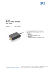
MP116E N-422 Linear Drive User Manual Version: 1.1.0 Date: 11.12.2014 This document describes the following product: N-422.50 PIShift OEM Linear Drive, 10 N, 35 mm, With Mounting Holes Physik Instrumente (PI) GmbH & Co. KG, Auf der Roemerstr. 1, 76228 Karlsruhe, Germany Phone: +49 721 4846-0, Fax: +49 721 4846-1019, E-mail: [email protected] Physik Instrumente (PI) GmbH & Co. KG is the owner of the following trademarks: PI®, PIC®, PICMA®, PILine®, PIFOC®, PiezoWalk®, NEXACT®, NEXLINE®, NanoCube®, NanoAutomation®, Picoactuator®, PInano® © 2014 Physik Instrumente (PI) GmbH & Co. KG, Karlsruhe, Germany. The text, photographs and drawings in this manual are protected by copyright. With regard thereto, Physik Instrumente (PI) GmbH & Co. KG retains all the rights. Use of said text, photographs and drawings is permitted only in part and only upon citation of the source. Original instructions First printing: 11.12.2014 Document number: MP116E, LFa, version 1.1.0 Subject to change without notice. This manual is superseded by any new release. The latest release is available for download (p. 3) on our website. Contents 1 About this Document 1.1 1.2 1.3 1.4 1.5 2 3 Goal and Target Audience of this User Manual ...................................................1 Symbols and Typographic Conventions ...............................................................1 Figures ..................................................................................................................2 Other Applicable Documents ................................................................................2 Downloading Manuals ..........................................................................................3 Safety 2.1 2.2 5 Intended Use ........................................................................................................5 General Safety Instructions ..................................................................................6 Product Description 3.1 3.2 3.3 1 7 Product View.........................................................................................................7 Product Labeling ...................................................................................................8 Scope of Delivery .................................................................................................9 4 Unpacking 11 5 Installation 13 5.1 5.2 6 General Notes on Installation .............................................................................13 Integrating the N-422 in a Mechanical System...................................................17 Start-Up and Operation 6.1 6.2 6.3 21 General Notes on Start-Up and Operation .........................................................21 Starting Up the N-422 with E-870 Drive Electronics ..........................................23 Operating parameters of the N-422 ....................................................................23 7 Maintenance 25 8 Troubleshooting 27 9 Customer Service 29 10 Technical Data 10.1 10.2 10.3 10.4 10.5 10.6 31 Specifications......................................................................................................31 10.1.1 Data Table ........................................................................................31 10.1.2 Maximum Ratings .............................................................................32 10.1.3 Ambient Conditions and Classifications ...........................................32 Drive Performance ..............................................................................................33 Lifetime ...............................................................................................................33 Dimensions .........................................................................................................34 Pin Assignment ...................................................................................................35 Suitable Drive Electronics ...................................................................................35 11 Old Equipment Disposal 37 12 EC Declaration of Conformity 39 1 About this Document 1 About this Document In this Chapter Goal and Target Audience of this User Manual ............................................................ 1 Symbols and Typographic Conventions ........................................................................ 1 Figures ........................................................................................................................... 2 Other Applicable Documents ......................................................................................... 2 Downloading Manuals ................................................................................................... 3 1.1 Goal and Target Audience of this User Manual This manual contains information on the intended use of the N-422. It assumes that the reader has a fundamental understanding of basic servo systems as well as motion control concepts and applicable safety procedures. The latest versions of the user manuals are available for download (p. 3) on our website. 1.2 Symbols and Typographic Conventions The following symbols and typographic conventions are used in this user manual: CAUTION Dangerous situation If not avoided, the dangerous situation will result in minor injury. Actions to take to avoid the situation. NOTICE Dangerous situation If not avoided, the dangerous situation will result in damage to the equipment. N-422 Linear Drive Actions to take to avoid the situation. MP116E Version: 1.1.0 1 1 About this Document INFORMATION Information for easier handling, tricks, tips, etc. Symbol/Label Meaning 1. Action consisting of several steps whose sequential order must be observed 2. Action consisting of one or several steps whose sequential order is irrelevant List item p. 5 Cross-reference to page 5 RS-232 Labeling of an operating element on the product (example: socket of the RS-232 interface) Warning sign on the product which refers to detailed information in this manual. 1.3 Figures For better understandability, the colors, proportions and degree of detail in illustrations can deviate from the actual circumstances. Photographic illustrations may also differ and must not be seen as guaranteed properties. 1.4 Other Applicable Documents The devices and software tools which are mentioned in this documentation are described in their own manuals. 2 Device Document E-870 Drive Electronics for PIShift Linear Drive E870T0001 Technical Note Version: 1.1.0 MP116E N-422 Linear Drive 1 About this Document 1.5 Downloading Manuals INFORMATION If a manual is missing or problems occur with downloading: Contact our customer service department (p. 29). INFORMATION For some products (e.g. Hexapod systems and electronics that are delivered with a CD), access to the manuals is password-protected. The password is stored on the CD. Availability of the manuals: Password-protected manuals: FTP download directory Follow the corresponding instructions for downloading. Freely available manuals: PI website Download freely accessible manuals 1. Open the website http://www.pi-portal.ws. 2. Click Downloads. 3. Click the corresponding product category. 4. Go to the corresponding product code. The available manuals are displayed. 5. Click the desired manual and save it on the hard disk of your PC or on a data storage medium. Download password-protected manuals 1. Insert the product CD in the PC drive. 2. Switch to the Manuals directory on the CD. 3. In the Manuals directory, open the Release News (file including releasenews in the file name). 4. Find the user name and the password in the section "User login for software download" in the Release News. 5. Open the FTP download directory (ftp://pi-ftp.ws). − N-422 Linear Drive Windows operating systems: Open the FTP download directory in Windows Explorer. MP116E Version: 1.1.0 3 1 About this Document 6. Log in with the user name and the password from the Release News. 7. In the directory of the corresponding product, go to the Manuals sub-directory. 8. Copy the desired manual to the hard disk of your PC or to a data storage medium. 4 Version: 1.1.0 MP116E N-422 Linear Drive 2 Safety 2 Safety In this Chapter Intended Use ................................................................................................................. 5 General Safety Instructions ........................................................................................... 6 2.1 Intended Use The N-422 is a laboratory device as defined by DIN EN 61010-1. It is intended to be used in interior spaces and in an environment which is free of dirt, oil, and lubricants. The N-422 is a linear drive for integration in motion systems that are used for positioning, adjustment and displacement of a moving object (load) in one axis. For integration, the mechanical system in which the N-422 is to be installed must have suitable guidings. The N-422 can be mounted horizontally or vertically. The N-422 linear drive uses the principle of inertia (stick-slip effect). The feed of the rod is produced by alternating static and sliding friction between the rod and a cyclically activated piezo actuator. The moving object (load) is coupled to the moving rod. When at rest, the drive is self-locking, requires no current and generates no heat. It holds the position with maximum force. The N-422 is not intended for continuous operation. For further information on the operating conditions of the N-422, see "Technical Data" (p. 31). The intended use of the N-422 is only possible in connection with suitable drive electronics that provide the required operating voltages. The drive electronics is not in the scope of delivery of the N-422. PI offers suitable drive electronics (see p. 35). External position sensors and a position controller are required for the closed-loop operation of a motion system with N-422 drive and drive electronics. N-422 Linear Drive MP116E Version: 1.1.0 5 2 Safety 2.2 General Safety Instructions The N-422 is built according to state-of-the-art technology and recognized safety standards. Improper use can result in personal injury and/or damage to the N-422. Only use the N-422 for its intended purpose, and only use it if it is in a good working order. Read the user manual. Immediately eliminate any faults and malfunctions that are likely to affect safety. The operator is responsible for the correct installation and operation of the N-422. Organizational Measures User manual Always keep this user manual available by the N-422. The latest versions of the user manuals are available for download (p. 3) on our website. Add all information given by the manufacturer to the user manual, for example supplements or Technical Notes. If you pass the N-422 on to other users, also turn over this user manual as well as other relevant information provided by the manufacturer. Only use the device on the basis of the complete user manual. Missing information due to an incomplete user manual can result in minor injury and property damage. Only install and operate the N-422 after having read and understood this user manual. Personnel qualification The N-422 may only be installed, started up, operated, maintained and cleaned by authorized and appropriately qualified personnel. 6 Version: 1.1.0 MP116E N-422 Linear Drive 3 Product Description 3 Product Description In this Chapter Product View ................................................................................................................. 7 Product Labeling ............................................................................................................ 8 Scope of Delivery .......................................................................................................... 9 3.1 Product View Figure 1: N-422: Product view 1 Base body 2 Coupling element (consisting of clamp, spring and end piece) for fastening the moving object 3 Moving rod 4 Connection cable The arrow indicates the polarity of the direction of motion when the base body of the N-422 is on the fixed part of the mechanical system and the rod is coupled to the moving part. N-422 Linear Drive MP116E Version: 1.1.0 7 3 Product Description Figure 2: N-422: Detailed view of the coupling element 1 Clamp 2 Spring 3 End piece 4 Moving rod 3.2 Product Labeling Figure 3: N-422: Position of the product labeling 8 Version: 1.1.0 MP116E N-422 Linear Drive 3 Product Description Position Labeling Description A N-422.50 Product name A Manufacturer's logo A WWW.PI.WS Manufacturer's address (website) A Country of origin: Germany Country of origin 114007694 Serial number (example), individual for each N-422 Meaning of the places (counting from left): 1 = internal information, 2 and 3 = manufacturing year, 4 to 9 = consecutive numbers B B Warning sign "Observe manual!" B CE conformity mark B Old equipment disposal (p. 37) 3.3 Scope of Delivery Item ID Items N-422.50 linear drive according to order 000044341 3 M2×16-A2 screws 3 M2×8-A2 screws 3 S2-A2 safety washers T6 Torx screwdriver for M2×16-A2 screws Allen wrench AF 1.5 spherical head for M2×8-A2 screws MP116E N-422 Linear Drive User manual (this document) in printed form MP116E Version: 1.1.0 9 4 Unpacking 4 Unpacking 1. Unpack the N-422 with care. 2. Compare the contents against the items covered by the contract and against the packing list. 3. Inspect the contents for signs of damage. If parts are missing or you notice signs of damage, contact PI immediately. 4. Keep all packaging materials in case the product needs to be returned. N-422 Linear Drive MP116E Version: 1.1.0 11 5 Installation 5 Installation In this Chapter General Notes on Installation ...................................................................................... 13 Integrating the N-422 in a Mechanical System ........................................................... 17 5.1 General Notes on Installation NOTICE Increased friction due to lateral forces on the rod! Lateral forces that act on the rod of the linear drive increase the friction between the rod and other components of the drive. Increased friction interferes with the motion of the rod and increases the wear of the drive components. Avoid lateral forces on the rod of the linear drive. Precisely align the base body, rod and guiding with each other over the entire travel range. If possible, use high-quality linear guidings that have been specially designed for high-precision applications (e.g. crossed roller bearings or roller bearings). Avoid manually moving the rod of the N-422. NOTICE Damage from pulling or moving out the rod! Completely pulling or moving the rod out from the base body will destroy the N-422. Do not pull or move the rod out from the base body of the N-422. Design the positioning system so that the free end of the rod still protrudes from the base body of the N-422 even when the travel range is used completely. Limit the travel range in a suitable way, i.e. with a mechanical hard stop in the positioning system. N-422 Linear Drive MP116E Version: 1.1.0 13 5 Installation NOTICE Damage from collision of the coupling element with the base body! If the coupling element collides with the base body of the N-422, damage or considerable wear to the N-422 can result. Design the positioning system so that no contact is possible between the coupling element and the base body of the N-422. NOTICE Damage from opening the base body! Opening the base body destroys the N-422. Do not open the N-422. NOTICE Warping of the base body due to mounting on uneven surfaces! Mounting the N-422 on an uneven surface can warp the base body and thus the linear drive. Warping of the base body reduces the feed force. Mount the N-422 on an even surface. The recommended evenness of the surface is 50 µm. In the case of applications with great temperature changes: Only mount the N-422 on surfaces that have the same or similar thermal expansion properties as the N-422 (e. g. stainless steel surfaces). NOTICE Heating up of the N-422 during operation! During operation, the N-422 emits up to 15 watts of heat, which can interfere with your application. 14 Install the N-422 so that the application is not impaired by the emitted heat. Ensure sufficient ventilation at the place of installation. Make sure that the complete bottom side of the N-422 is in contact with the surface on which the N-422 is mounted. If possible: Observe the optimum operating conditions (duty cycle, ambient temperature), see "Lifetime" (p. 33). Version: 1.1.0 MP116E N-422 Linear Drive 5 Installation NOTICE Damage from unsuitable cables! Unsuitable cables can damage the electronics. Only use cables provided by PI for connecting the N-422 to the electronics. INFORMATION If the N-422 becomes contaminated with dirt, oil, lubricant or condensation, the dynamic force and the velocity of the drive will decrease. If necessary, install the entire system in a case to protect it against contamination. Prevent condensation from forming on the N-422. If condensation has formed on the N-422, let the drive dry before start-up. INFORMATION When the N-422 is installed in a mechnical system that is to be operated in closedloop mode, you need an external position sensor such as a linear encoder (not in the scope of delivery). Furthermore, the electronics must be able to read out and process the signals of the external position sensor. Observe the installation instructions of the manufacturer when installing the position sensor. Mount the position sensor as closely as possible to the intended motion. Observe the input and output signals of the electronics used to operate the N422. INFORMATION The moving object is fastened to the coupling element of the N-422. N-422 Linear Drive MP116E Version: 1.1.0 15 5 Installation Directions of motion When the base body of the N-422 is on the fixed part of the mechanical system and the rod is coupled to the moving part, the polarity of the direction of motion corresponds to that shown in the following figure. Figure 4: Directions of motion of the N-422 For further information on the operating conditions, refer to the "Technical Data" section (p. 31). 16 Version: 1.1.0 MP116E N-422 Linear Drive 5 Installation 5.2 Integrating the N-422 in a Mechanical System Figure 5: Example of the integration of the N-422 in a mechanical system 1 N-422 Linear Drive Moving sled 2 Mounting fixture for the coupling element of the N-422 3 Mounting fixture for the base body of the N-422 4 Base body of the mechanical system 5 Guiding MP116E Version: 1.1.0 17 5 Installation Figure 6: Mounting holes in the base body of the N-422 Figure 7: Mounting holes in the coupling element of the N-422 18 Version: 1.1.0 MP116E N-422 Linear Drive 5 Installation Figure 8: N-422: Maximum permissible angular misalignment between the mounting fixtures for the base body and coupling element (figure not true to scale) Prerequisites You have read and understood the general notes on installation (p. 13). The N-422 is not connected with the drive electronics. You have provided a suitable mechanical system: − Angular misalignment between the mounting fixtures for the base body and coupling element is within the tolerance limits (see above figure) − M2 mounting holes with a suitable depth are present in the surface and the moving object. The position of the mounting holes in the base body and the coupling element of the N-422 can be found in the dimensional drawing (p. 34). N-422 Linear Drive MP116E Version: 1.1.0 19 5 Installation Tools and accessories Mounting accessories (in the scope of delivery) − 2 M2×16-A2 screws − 2 M2×8-A2 screws − 2 S2-A2 safety washers − T6 Torx screwdriver for M2×16-A2 screws − Allen wrench AF 1.5 spherical head for M2×8-A2 screws Integrating the N-422 in a mechanical system 1. Place the N-422 on the surface so that the mounting holes in the base body of the N-422 are above the mounting holes in the surface. 2. Fasten the base body on the surface with the M2×16-A2 screws and the S2A2 safety washers. − Tighten the screws only slightly. 3. Fasten the clamp of the coupling element to the moving object with the M2×8A2 screws. − Tighten the two screws with the same torque so that both contact surfaces of the clamp lie on the moving object and the spring is equally loaded. 4. Tighten the M2×16-A2 screws for fastening the base body with a torque of 50 Ncm. 20 Version: 1.1.0 MP116E N-422 Linear Drive 6 Start-Up and Operation 6 Start-Up and Operation In this Chapter General Notes on Start-Up and Operation .................................................................. 21 Starting Up the N-422 with E-870 Drive Electronics ................................................... 23 Operating parameters of the N-422 ............................................................................. 23 6.1 General Notes on Start-Up and Operation CAUTION Risk of crushing by moving parts! There is a risk of minor injuries caused by crushing which can occur between the moving parts of the linear drive and a stationary part or obstacle. Keep your fingers away from areas where they can get caught by moving parts. NOTICE Operating voltage too high or incorrectly connected! Operating voltages that are too high or incorrectly connected can cause damage to the N-422. Only operate the N-422 with controllers/drivers and original accessories from PI. Do not exceed the operating voltage range (p. 32) for which the N-422 is specified. Only operate the N-422 when the operating voltage is properly connected; see "Pin Assignment" (p. 35). NOTICE Operating frequency too high! An operating frequency that is too high can cause damage to the N-422. Only operate the N-422 with controllers/drivers and original accessories from PI. Do not exceed the operating frequency range (p. 32) for which the N-422 is specified. N-422 Linear Drive MP116E Version: 1.1.0 21 6 Start-Up and Operation NOTICE Damage from pulling or moving out the rod! Completely pulling or moving the rod out from the base body will destroy the N-422. Do not pull or move the rod out from the base body of the N-422. Only put the N-422 into operation when it has been installed and completely assembled in a positioning system with a limited travel range. NOTICE Increased friction due to lateral forces on the rod! Lateral forces that act on the rod of the linear drive due to manual motion increase the wear on the components of the drive. Avoid manually moving the rod of the N-422. NOTICE Damage from collision of the N-422 with the hard stop! When the hard stop of the positioning system has been reached or the drive is blocked, but the N-422 is still being actuated, this can cause damage or considerable wear to the N-422. Do not place any objects in areas where they can get caught by moving parts. Do not continue to actuate the N-422 at the end of the travel range. INFORMATION The drive electronics is adapted via parameters to the N-422. Changing parameter values can cause undesirable results. Only operate the N-422 when the parameters of the drive electronics have been correctly set, see "Operating Parameters of the N-422" (p. 23). For further information on the operating conditions, refer to the "Technical Data" section (p. 31). The N-422 is started up with the E-870 (p. 35) drive electronics from PI. 22 Version: 1.1.0 MP116E N-422 Linear Drive 6 Start-Up and Operation 6.2 Starting Up the N-422 with E-870 Drive Electronics Prerequisites You have read and understood the general notes on start-up and operation (p. 21). The N-422 has been installed properly (p. 13). The E-870 drive electronics has been properly installed and all connections on the E-870 have been set up (see E870T0001 Technical Note). Starting up the N-422 with E-870 drive electronics 1. Make sure that the parameters of the drive electronics have been correctly set, see "Operating Parameters of the N-422" (p. 23). 2. Provide the control signal required for operating the system. Details can be found in the E870T0001 Technical Note. 6.3 Operating parameters of the N-422 The following table lists the settings for the parameters of the drive electronics. Parameter Parameter in E-870 Drive Electronics Value Unit Operating frequency in step mode PIShift Frequency 23 kHz Operating voltage, lower limit PIShift Lower Supply Voltage 0 V Operating voltage, upper limit PIShift Upper Supply Voltage 48 V Charging current during forward motion PIShift Forward Current 0.6 A Charging current during backward motion PIShift Backward Current -0.6 A Duty cycle of the current source during the output of one period of the modified sawtooth signal in step mode PIShift Charge Cycle 1 - N-422 Linear Drive ID 0x1F000400 ID 0x1F000100 ID 0x1F000000 ID 0x1F000200 ID 0x1F000300 ID 0x1F000500 MP116E Version: 1.1.0 23 7 Maintenance 7 Maintenance When the N-422 is operated in a clean environment, no maintenance work is necessary. If you would like your device to be serviced, please contact our customer service department (p. 29). N-422 Linear Drive MP116E Version: 1.1.0 25 8 Troubleshooting 8 Troubleshooting Problem Possible Causes Solution Reduced performance and increased wear Warped base body Mount the N-422 horizontally on an even surface. The recommended evenness of the surface is 50 µm. Increased friction due to lateral forces on the rod Avoid lateral forces on the rod of the N-422. Precisely align the base body, rod and guiding with each other over the entire travel range. If possible, use high-quality linear guidings (e. g. crossed roller bearings or roller bearings). Excessive load Excessive counterforces in the direction of motion Reduce the load. Observe the information in the "Drive Performance" section (p. 33). In the case of vertical mounting, ensure gravity compensation so that the maximum load (p. 31) is not exceeded. Contact our customer service department (p. 29) in this case. Check the settings for the parameters of the drive electronics (details see "Operating Parameters of the N-422" (p. 23) and E870T0001 Technical Note). No or limited motion Parameters of the drive electronics incorrectly set If the problem that occurred with your system is not listed in the table above or cannot be solved as described, contact our customer service department (p. 29). N-422 Linear Drive MP116E Version: 1.1.0 27 9 Customer Service 9 Customer Service For inquiries and orders, contact your PI sales engineer or send us an e-mail (mailto:[email protected]). If you have questions concerning your system, have the following information ready: Product codes and serial numbers of all products in the system Firmware version of the controller (if present) Version of the driver or the software (if present) Operating system on the PC (if present) The latest versions of the user manuals are available for download (p. 3) on our website. N-422 Linear Drive MP116E Version: 1.1.0 29 10 Technical Data 10 Technical Data In this Chapter Specifications .............................................................................................................. 31 Drive Performance....................................................................................................... 33 Lifetime ........................................................................................................................ 33 Dimensions .................................................................................................................. 34 Pin Assignment ............................................................................................................ 35 Suitable Drive Electronics............................................................................................ 35 10.1 Specifications 10.1.1 Data Table N-422.50 Unit Tolerance Motion and positioning Travel range 35 mm Step size without load 0.5 µm typ. Velocity 10 mm/s max. Stiffness, de-energized 4 N/µm min. Holding force, de-energized 10 N min. Push / pull force 7 N min. Max. step frequency 23 kHz Motor voltage 48 Vpp 0 °C to 50 °C °C Mechanical properties Drive properties Miscellaneous Operating temperature range Casing material stainless steel Mass 50 Connector Mini DIN 4-pin Cable length 1.5 Recommended controller/driver E-870 Dimensions 19 × 13 × 16 (base body) plus rod / coupling element N-422 Linear Drive MP116E g ±10 % m ±10 mm mm Version: 1.1.0 31 10 Technical Data 10.1.2 Maximum Ratings N-422 linear drives are designed for the following operating data: Device Maximum Operating Voltage Maximum Operating Frequency Maximum Power Consumption N-422 48 Vpp 23 kHz 15 W 10.1.3 Ambient Conditions and Classifications The following ambient conditions and classifications must be observed for the N-422: Area of application For indoor use only Maximum altitude 2000 m Air pressure 1100 hPa to 0.1 hPa (corresponds to roughly 825 Torr to 0.075 Torr) Relative humidity Highest relative humidity 80% for temperatures up to 31°C Decreasing linearly to 50% relative humidity at 40°C 32 Operating temperature 0 °C to 50 °C Storage temperature -20°C to 75°C Transport temperature -20°C to 75°C Overvoltage category II Protection class I Degree of pollution 1 Degree of protection according to IEC 60529 IP30 Version: 1.1.0 MP116E N-422 Linear Drive 10 Technical Data 10.2 Drive Performance Velocity and dynamic force The following graph can be used to estimate the dynamic force (push/pull force, force in N) of the N-422 at different velocities. N-422.50 Figure 9: Velocity vs. dynamic force (push/pull force) of the N-422 10.3 Lifetime The N-422 can achieve a lifetime of 2000 m under optimum operating conditions and with full use of the travel range. Optimum operating conditions of the N-422: N-422 Linear Drive Duty cycle: Maximum 50 % Running time: Maximum 10 seconds Ambient temperature: Room temperature Air pressure: Normal pressure Proper installation of the N-422 (p. 13) Proper settings of the drive electronics, see "Operating Parameters of the N422" (p. 23) MP116E Version: 1.1.0 33 10 Technical Data 10.4 Dimensions Dimensions in mm. Note that the decimal places are separated by a comma in the drawings. Figure 10: Dimensions of N-422, position of the clamp when installed, spring loaded 34 Version: 1.1.0 MP116E N-422 Linear Drive 10 Technical Data 10.5 Pin Assignment Mini DIN connector (4-pin (m)) Figure 11: Mini-DIN connector, 4-pin (m) Pin No. Function Color of the wire in the connection cable 1 Piezo - GND Black 2 Piezo + (0 to 48 V) Red 3 Not connected 4 Not connected The cable shield is connected to the connector shell. 10.6 Suitable Drive Electronics To operate the N-422, you need suitable drive electronics (not in the scope of delivery). The following drive electronics are available: Drive Electronics Description E-870.10 PIShift Piezomotor / PiezoMike Drive Electronics, 1 Channel, OEM Board E-870.11 PIShift Piezomotor / PiezoMike Drive Electronics, 1 Channel, OEM Board with Connector Strip = E-870.10 plus carrier board E-870.41 PIShift Piezomotor / PiezoMike Drive Electronics, 4 Channels, OEM Board with Connector Strip = E-870.10 plus carrier board and 1:4 demultiplexer N-422 Linear Drive MP116E Version: 1.1.0 35 11 Old Equipment Disposal 11 Old Equipment Disposal In accordance with the applicable EU law, electrical and electronic equipment may not be disposed of with unsorted municipal wastes in the member states of the EU. When disposing of your old equipment, observe the international, national and local rules and regulations. To meet the manufacturer’s product responsibility with regard to this product, Physik Instrumente (PI) GmbH & Co. KG ensures environmentally correct disposal of old PI equipment that was first put into circulation after 13 August 2005, free of charge. If you have old PI equipment, you can send it postage-free to the following address: Physik Instrumente (PI) GmbH & Co. KG Auf der Römerstr. 1 D-76228 Karlsruhe, Germany N-422 Linear Drive MP116E Version: 1.1.0 37 12 EC Declaration of Conformity 12 EC Declaration of Conformity For the N-422, an EC Declaration of Conformity has been issued in accordance with the following European directives: 2004/108/EC, EMC Directive 2011/65/EU, RoHS Directive The applied standards certifying the conformity are listed below. EMC: EN 61326-1:2013 Safety: EN 61010-1:2010 RoHS: EN 50581:2012 N-422 Linear Drive MP116E Version: 1.1.0 39