Transcript
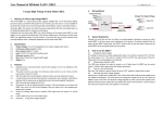
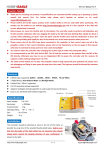
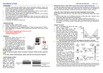
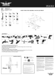
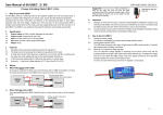
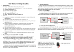
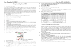
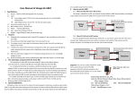
User Manual of 5A HV UBEC
5 Amps High Voltage Switch Mode UBEC
1.
2.1.
2.2.
2.3.
2.4.
2.5.
2.6.
2.7.
3.
3.1.
3.2.
3.3.
3.4.
3.5.
3.6.
3.7.
3.8.
3.9.
4.
Why do you need a high voltage UBEC?
The 5A-HV-UBEC is a switch-mode DC-DC regulator supplied with a 3-10 cells lithium battery
pack and outputs a consistent safe power for your receiver, gyro and servos. It is very suitable for
big electric RC models such as fixed-wing aircrafts and helicopters which use more than 4 cells
lithium battery.
Using this UBEC, the receiver can obtain the power supply directly from the main battery pack, so
the additional battery pack for receiver is unnecessary.
Compared with the linear mode UBEC, the overall efficiency of the switch-mode UBEC is much
higher, so it can extend the working time of the receiver battery pack, and because a switch mode
UBEC can significantly reduce the heat emission, it can avoid the loss of control caused by the
over-heat problem which is frequently happened with the linear mode UBEC.
2.
Doc Ver:
Specification:
Output Voltage: 5V or 6V (Changeable with an jumper )
Continuous output current: 5 Amps
Burst output current: 7.5 Amps
Input: 8V-42V (3-10 cells lithium battery pack)
Quiescent current: 20mA
Size: 48mm*27mm*9mm (length*width*height)
Weight: 30g
Features:
Designed with an advanced switch mode DC-DC regulator IC, the max efficiency of the
chip is up to 92%.
The output current is very large, the continuous output current is up to 5 Amps, and the
burst output current is up to 7.5 Amps.
With the output short-circuit protection function.
A metal shield covers almost all the electronic components, and a filter (ferrite ring) is
attached with the output wires to significantly reduce the electromagnetic interference.
With ultra-wide input voltage from 8V-42V.
Safe power on with the polarity protection function. If the input polarity is not correct, the
UBEC can’t work, but it will not be damaged. What you need to do is just swapping the
battery pack’s polarity.
Shows the working status with an indicator (LED), it lights when the output is in normal
range.
It has a switch to turn on or turn off the output.
Accessory: A step-down voltage regulator with 0.7V down. (from 6.0V to 5.3V)
Wiring Method
Output
Input
Switch
5A UBEC
6V
5V
5.
HW-07-080602.1
Jumper for output
voltage selection
Special Explanation
Although we have tried our best to reduce the electromagnetic interference caused by switch
model UBEC, it may still cause some interference to the receiver. So please install the filter (ferrite
ring) far away from the UBEC’s main board, and DON’T stack the filter on the main board. Please
put the whole UBEC as far as possible away from the receiver.
6.
How to Use the UBEC?
6.1.
Change the output voltage
The output voltage is chosen by a jumper. Please look at the upper picture, there are 3 pins at the
right corner, the upper one is Pin1, the middle one is Pin2, and the bottom one is Pin3. If the switch
is located at Pin1 and Pin2, the output power is 6V. If the switch is located at Pin2 and Pin3, the
output power will be 5V.
6.2.
Working status indicator (LED)
The LED shows whether the output is normal or not. It lights when the UBEC has the normal
output. If it doesn’t light, please check the battery connections.
6.3.
Turn on or turn off the output
Move the switch to the "ON" position to turn on the output; Move the switch to the “OFF" position to
turn off the output.
6.4.
About the 0.7V step-down voltage regulator
Allowing use of Futaba servo models 9241, 9251, 9253, 9254, 9255, 9256 and other digital servos
not capable of handling 6V. This small device can change the voltage from 6V to 5.3V. When the
UBEC output is set to 6V, the step-down voltage regulator is useful.
Method: Just connect the regulator inline between the Gyro and the rudder servo (Or between the
receiver and the servo), that’s OK!
If you are using a servo that can accept 6V input, the regulator is not required.