Transcript
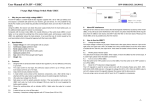
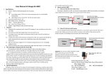
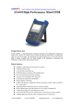
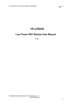
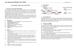
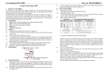
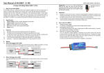
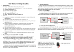
Thank you for purchasing this product! Devices used on RC models can be
dangerous, any improper use may cause personal injury and damage to devices,
ATTENTION
control over the use, installation and maintenance of this product or other related
electronics, no liability may be assumed nor will be accepted for any damages,
CAUTIONS
losses or costs resulting from the use of the product. Besides, we don’t shoulder any
responsibility for any losses caused by unauthorized modifications to our product.
The last but not least, we have the right to change the product design, appearance,
01 Introduction
The UBEC is an external switching mode DC-DC regulator; it draws the DC voltage from 2-6S Lipo
battery, drops it to a voltage level that is suitable for receivers and other electronic devices, and keep
providing the stable current output of up to 10Amp. As the UBEC has such a powerful output
capability, so it is particularly applicable for large helicopters and fixed-wing aircrafts.
02 Features
Specifications
to the output end and causing damages to receivers, servos and other electronic devices.
and thermal protection make the use more safe and reliable.
the receiver.
Model
UBEC-10A
Input Voltage
6V-25.2V (2-6S LiPo)
Output Voltage
5.0V/6.0V/7.4V/8.4V
Output Amperage
Continuous Current: 10A, Peak Current: 20A
Dimension
43.1x32.3x12.5mm
Weight
36g
03 Change the Output Voltage
Change the Output Voltage
There are 3 dip switches on the UBEC. User can change the output voltage in the following way.
Set to 5.0V: Dip switch #1 = Off, #2 = Off, #3 = Off.
Note:
Set to 6.0V: Dip switch #1 = Off, #2 = Off, #3 = On.
"X" indicates either
Set to 7.4V:
the dip switch is on
Set to 8.4V:
ATTENTION
Note:
the position of ON
or OFF is OK.
Face to the front panel of the UBEC, from left to right, the dip switches are #1, #2, #3 .
04 Wiring
UBEC 10A
Switch
Battery
Servo
Receiver
1. When the ESC has no built-in BEC,
the receiver.
2. When the ESC has a built-in BEC,
Tips:
Note:
1. As the switching mode DC-DC regulator may produces some electromagnetic interference in operation and affects
the ESC, and then insulate it with a bit of electrical tape for
further use. By this method, you needn’t cut the red wire in
the control cable.
receivers, please keep the UBEC at least 5cm away from receivers when it’s installed.
Take the pin with
red wire out
05 Explanation for the Status LED
the input wires are well connected and there’s nothing wrong with the battery pack.
2. Polarity of the power supply must be aligned with the polarity of the UBEC at the input end, incorrect polarity is not
permitted. So please ensure the correct connection before use; otherwise, the UBEC will be seriously damaged.