Transcript
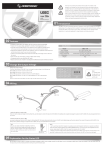
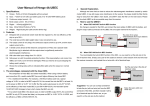
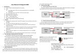
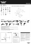
User Manual of 8A UBEC(2- 6S)
HW-SM813ENG-20130121
Suggestion: You can use a sharp screwdriver to
8 Amps Switching-Mode UBEC (2-6S)
1.
take the pin (with red wire) out from the BEC
connector of the ESC, and then insulate it with a bit of
electrical tape for further use, so you needn’t cut the
red wire by this method.
Why do you need UBEC?
The 8A-UBEC (2-6S) is a switching-mode DC-DC regulator supplied with 2-6S Lipo battery pack; it
outputs a consistent safe voltage for your receiver, gyro, servos and other electronic equipments.
Compared with the linear mode BEC, the efficiency of the switching-mode BEC is much higher
especially when the input voltage is higher than 14.8V (4S Lipo). So the switching-mode BEC is
strongly recommended when the RC model uses high voltage battery pack (more than 4S Lipo or 12
cells NiMH). The UBEC is very suitable for big scale RC helicopters and big fixed-wing aircrafts.
5.
5.1.
5.2.
2.
2.1.
2.2.
2.3.
2.4.
2.5.
3.
3.1.
3.2.
3.3.
3.4.
3.5.
4.
Specification:
Output voltage: 5.2V/8A or 6V/8A (Selectable by the switch).
Output current: Continuous 8A, burst 15A.
Input: 5.5V-26V (2-6S Lipo or 5-18 cells NiMH).
Size: 62mm*27.5mm*10mm (length*width*height)
Weight: 24.5g
6.
6.1.
6.2.
Features:
Equipped with the advanced switching-mode DC-DC regulator IC.
The output current is big enough for all electronic equipments in RC model.
A metal shield covers all the electronic components, and a ferrite ring filter is attached with
the output wire which significantly reduces the electromagnetic interference.
A LED shows the working status, it lights when the output is in normal range.
Accessory: A step-down voltage regulator of 0.7V down (from 6.0V to 5.3V).
6.3.
Attentions
Although we have tried our best to reduce the electromagnetic interference caused by this
switching-model UBEC, but it still may cause some interference to receiver. So please install
the UBEC far away from the receiver (The distance > 5cm is recommended).
The input polarity must be correct; otherwise the UBEC will be damaged immediately. Please
check the polarity carefully before connecting the battery pack.
How to Use the UBEC?
Change the output voltage
The voltage is changeable by using the output-voltage selection switch.
Working status indicator (LED)
The LED shows the status of the output. It lights when the UBEC works normally. If it couldn’t
light, please check the battery connections.
About the 0.7V step-down voltage regulator
The 0.7V step-down voltage regulator is necessary for the servos cannot work with 6V
(including Futaba servo 9241, 9251, 9253, 9254, 9255, 9256 and etc). It changes the voltage
from 6V to 5.3V. When the UBEC output is set to 6V, please connect the 0.7V step-down
regulator between the receiver and the above servos.
If a servo can work with 6V input, then the 0.7V regulator is unnecessary.
Wiring:
4.1. When ESC hasn’t built-in BEC
No change is needed for the ESC, just connect the input wires of UBEC to the battery, and plug
the output lead (connector) of the UBEC into one spare channel of the receiver.
Battery
Pack
+
-
The color of trio wires:
white/red/black (from top to bottom)
red
ESC
black
Receiver
UBEC
4.2. When ESC has built-in BEC
You must disable the built-in BEC of the ESC (that is, cut the red wire in the trio of Rx (receiver)
wires.
Battery
Pack
+
-
Cut the red wire in the trio of
receiver wires
red
ESC
black
Receiver
UBEC
- 1 -