1
ADT-CNC4240
Milling CNC System
User Manual
Adtech (Shenzhen) CNC Technology Co., LTD
Address: 5th floor,27-29th Bulding,Tianxia IC Industrial Park,MaJiaLong,Yiyuan Road,
Nanshan District, Shenzhen City, China
TEL:+86-755-26099116
P.C: 518052
FAX:+86-755-2672 2718
Website://www.adtechen.com
ADT-CNC4240 铣 床 数 控 系 统
Copyright Notice
The property rights of all the parts of the manual belong to Adtech CNC Co., Ltd.
(Adtech for short), and any form of imitation, copying, transcription or translation by any
company or individual without the permission is prohibited. This manual does not include
any form of assurance, standpoint expression, or other intimations. Adtech and the stuffs
have no responsibility for any direct or indirect disclosure of the information, benefit loss or
business termination of this manual of the quoted product information. In addition, the
product and the information mentioned in this manual are for reference only, and the
content is subjected to change without notice.
ALL RIGHTS RESERVED!
ADTECH CNC Co., Ltd
Adtech CNC Co.,LTD
-1-
ADT-CNC4240 铣 床 数 控 系 统
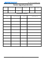
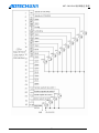
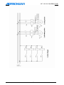
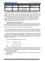
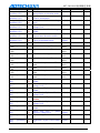
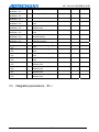
Version Upgrading Instruction
Program NO
First update
Version Number
Total page
XT20061224
2011-7-19
A1001
193
Edit
Printer
engineer
engineer
Yang Jipeng
Yang Jipeng
calibration records
Date
Adtech CNC Co.,LTD
version/page
result
-2-
confirmation
ADT-CNC4240 铣 床 数 控 系 统
Notice
Transportation and storage:
1.The product packing case piles the repeat not to be possible to surpass six
2.Cannot climb up in the product packing case, stand or the laying aside heavy
3. cannot use and the product connected electric cable dragging or the
transporting product
4. refuses the collision, to scratch the kneading board and the display monitor
5. product packing case should avoid moist, the insolation as well as the rain
drenches
Opens a box and check :
1. after opening the packing, please confirm whether is the product
2. inspection product which you purchase in the transportation whether to have
on the way damages
3. comparison detailed list to confirm various parts are whether complete,
whether there is appendix or transportation damage situations and so on to
damage
4. like existence product model symbol, not to lack, please promptly relate with
Our company
Connection:
1. participates in the wiring and the inspection personnel must be has the
corresponding ability specialists
2. product to earth reliably, the earth resistance should be smaller than 4 ohms,
cannot use the neutral axis (zero curve) to replace the grounding
3. wiring to be correct, be reliable, in order to avoid causes the product
breakdown or the unexpected consequence
4. with the product connection surge absorber diode must according to the
stipulation direction connection, otherwise before will damage product
5. to insert pulls out the plug or turns on the product engine case, must shut
off the product power source
Overhaul
1. before the overhaul either replaces the primary device, must the dump
2. have when the short circuit or the overload should the trouble shooting, after
the trouble shooting, if only then starts
3. not to be possible passes the power failure frequently to the product, after the
power failure, to electrify, time interval at least 1 minute
Others
1. without the permission, please arbitrarily do not turn on the cabinet.
2. the long time does not use, please dump.
3. the special attention do not let the dust, the powdered iron enter the
controller.
4. outputs the relay, if uses the non-solid state relay, then must in the relay
winding the parallel after flow diode. The inspecting office receives a
telegram the source whether to meet the requirement, ceases burns out the
controller.
5. controller's life and the ambient temperature have the very big relations, if
processes the scene hyperpyrexia, pays respects installs the radiation
Adtech CNC Co.,LTD
-3-
ADT-CNC4240 铣 床 数 控 系 统
ventilator. Controller permission work ambient temperature scope in 0℃-60
℃ between. 6. avoids, in the high temperature, moist, the multi-dust or have
in the caustic gas environment to use. 7. in the vibration intense place,
should add the rubber crash pad to carry on the cushion.
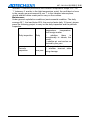
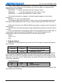
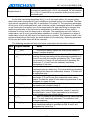
Maintenance
Under general exploitation conditions (environmental condition: The daily
average 30℃, the load factor 80%, the service factor daily 12 hours), please
press the following project to carry on the daily inspection and the periodic
inspection.
1.confirmation
ambient
temperature,
temperature,
dust foreign matter
2.
whether
there
is
Daily
Daily inspection
exceptionally to vibrate, the
sound
3. whether air vent and so on
blocked by the yarn
Periodic
inspection
Adtech CNC Co.,LTD
1. Firm part whether loose
2. whether terminal table
one year being damage
-4-
ADT-CNC4240 铣 床 数 控 系 统
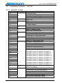
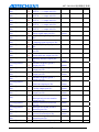
Contents
1 SUMMARY OF SPECIFICATION ...................................................................................... - 7 1.1
1.2
PRODUCTION SPECIFICATIONS ............................................................................................- 7 WORKING ENVIRONMENTS .................................................................................................- 9 -
2 HARDWARE INTERFACE DEFINITION AND DESCRIPTIONS OF CONNECTION ...10 2.1
OPERATION PANEL .............................................................................................................- 10 2.2.1 EXTERNAL INTERFACE DRAWING ...........................................................................................- 10 2.2.2 PLANS TO INSTALL SIZE ........................................................................................................- 11 2.2.3 NOTES INSTALLATION...........................................................................................................- 11 2.2 INTERFACE DEFINITION .....................................................................................................- 14 2.3.1 MOTOR&DRIVER CONTROL INTERFACE(XS1..XS4) ..........................................................- 14 2.3.2 DIGITAL INPUT INTERFACE(XS5).....................................................................................- 16 2.3.3 DIGITAL OUTPUT INTERFACE(XS6) .................................................................................- 18 2.3.4 MANUAL CONTROL BOX INTERFACE(XS7) .......................................................................- 20 2.3.5 ANALOG OUTPUT INTERFACE(XS8) ..................................................................................- 21 2.3.6 INTERFACE OF SPINDLE ENCODER(XS12)........................................................................- 21 2.3.7 RS232 TRANSMISSION INTERFACE(XS9) ........................................................................- 24 2.3.8 USB MEMORY INTERFACE TO CONNECT(XS10) ..................................................................- 24 2.3.9 PC USB COMMUNICATION INTERFACE(XS11) .................................................................- 24 2.3 ELECTRIC CONNECTION DRAWING...................................................................................- 25 2.3.1 SCHEMATIC SYMBOL .............................................................................................................- 25 2.3.2 POWER PLANS TO CONNECT ..................................................................................................- 26 2.3.3 SERVO DRIVER CONNECTION DIAGRAM .............................................................................- 27 2.3.4 STEPPER CONNECTION DIAGRAM .......................................................................................- 28 2.3.5 IO ELECTRIC CONNECTION DIAGRAM ................................................................................- 28 3 G CODE PROGRAM ........................................................................................................... - 32 3.1 BASIC KNOWLEDGE OF PROGRAM .....................................................................................- 32 3.1.1 MOTION DIRECTION AND NAME OF CONTROL AXIS .................................................................- 32 3.1.2 MACHINE TOOL COORDINATE SYSTEM AND WORKPIECE COORDINATE SYSTEM(G53、G54~G599)
- 34 3.1.3 THE MODE STATUS FUNCTION AND THE NON-MODE STATUS FUNCTION ...................................- 36 3.1.4 FEEDING ..............................................................................................................................- 36 3.1.5 PROGRAM STRUCTURE ..........................................................................................................- 37 3.2
PREPARATORY FUNCTIONS(G CODE)..........................................................................- 40 3.2.1 G CODE OF LIST ...................................................................................................................- 40 3.2.2 INTERPOLATION FUNCTIONS(G00、G01、G02、G03) .................................................- 41 3.2.3 PAUSE INSTRUCTION(G04).............................................................................................- 44 3.2.4 SELECT PLANE(G17、G18、G19) ................................................................................- 44 3.2.5 COORDINATE INSTRUCTION(G53~G59、G591~G599、G92) ..................................- 45 3.2.6 INSTRUCTIONS RELATED TO REFERENCE POINT(G27、G28、G29).................................- 48 -
Adtech CNC Co.,LTD
-5-
ADT-CNC4240 铣 床 数 控 系 统
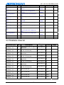
3.2.7
3.2.8
3.3
3.3.1
3.3.2
3.3.3
3.5
CUTTER COMPENSATION(G40、G41、G42、G43、G44、G49) ................................- 50 HOLE MACHINING CYCLE(G73~G89).............................................................................- 81 ASSISTANT FUNCTION(M,S,T) ..............................................................................- 94 M CODE ..............................................................................................................................- 94 S CODE ...............................................................................................................................- 96 T CODE ...............................................................................................................................- 97 G CODE TEMPLATE PROGRAMMING(DXF LEAD-IN RULE PROGRAMMING)...................- 112 -
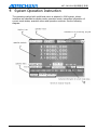
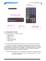
4 SYSTEM OPERATION INSTRUCTION ...................................................................... - 116 4.1
4.1.1
4.1.2
4.1.3
4.1.4
4.1.5
4.2
4.2.1
4.2.2
4.2.3
4.2.4
4.2.5
4.2.6
4.2.7
4.3
OPERATION MODE ...........................................................................................................- 117 AUTO MODE(HANDWHEEL,STARTUP AND PROGRAM INSPECTION) ........................................- 117 MANUAL MODE ..................................................................................................................- 118 MDI .................................................................................................................................- 118 HANDWHEEL OR SINGLE-STEP MODE ...................................................................................- 118 ZERO MODE .......................................................................................................................- 118 SYSTEM MENU .................................................................................................................- 119 POSITION INTERFACE(POSITION) ..................................................................................- 120 PROGRAM INTERFACE(PROGRAM) ..................................................................................- 122 PARAMETER INTERFACE ......................................................................................................- 126 TOOLS COMPENSATION PARAMETERS PICTURE(CUTTING TOOLS OFFSET)..........................- 128 SETTING PICTURE OF THE WORKPIECE COORDINATE SYSTEM ................................................- 128 CONTROLLER DIAGNOSIS INTERFACE (DIAGNOSING)...........................................................- 132 MACRO VARIABLE VIEW INTERFACE (MACRO VARIABLE) .....................................................- 133 INFORMATION ON INSTRUCTIONS IN CURRENT MODE STATUS ...................................- 133 -
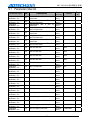
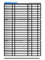
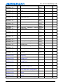
5 PARAMETER ..................................................................................................................... - 134 5.1
5.2
5.3
5.4
5.5
5.6
5.7
5.8
PARAMETER INDEX LIST ..................................................................................................- 135 PARAMETER INDEX LIST ..................................................................................................- 148 INTEGRATIVE PARAMETERS(P1.) ..............................................................................- 151 AXIS PARAMETER CONFIGURATION(P2.)...................................................................- 167 MANAGER PARAMETER(P3.) .....................................................................................- 179 TOOL MAGAZINE PARAMETER(P4.) ...........................................................................- 184 PARAMETER OF SPINDLE(P5.) ....................................................................................- 185 IO CONFIGURATION(P6.) ...........................................................................................- 188 -
6 SYSTEM ALARMING ....................................................................................................... - 191 6.1
6.2
NC PROGRAM EXECUTING ALARMING ............................................................................- 191 SYSTEM ENVIRONMENT ALARMING .................................................................................- 192 -
Adtech CNC Co.,LTD
-6-
ADT-CNC4240 铣 床 数 控 系 统
1 Summary of Specification
ADT-CNC4240 is a standard controlling system for milling machines characterized by
the economic cos s, employs the standard G codes for programming and is widely used in
the automatic equipment with length control in the products. The general specification and
the maintenance of this product are described as follows:
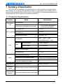
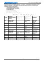
1.1 Production Specifications
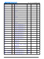
Function
Controllable
axes
Name
Specification
4axis (X,Y,Z,A )
Controlled axis
0.001mm
Min setting unit
Input command Min move unit
Feed
Hand
0.001mm
Max instruction value
±9999.999 mm
fast feedrate
X-axis、Y-axis、Z-axis、
A-axis:9999mm/min(max)
feed per minute
1~ 9999 mm/min
feed per rotate
1~ 500 mm/ratio
range
Auto acc and dec speed
Yes
feed speed rate
10~ 150%
Hand continuous feeding
Yes
Reference point for manual return
one or three axes return to return
to reference point simultaneously
single step /handwheel function
Yes
G00,G01,G02/G03
Interpolation Location,Linear,Full cycle arc
Operation
mode
4 axes linear interpolation
2 axes arc interpolation
Simultneous controllable axes number
MDI,automation,manual,single step,edit
Yes
Commissioning
Yes
Trial running,single program,hand wheel
function
Adtech CNC Co.,LTD
-7-
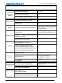
ADT-CNC4240 铣 床 数 控 系 统
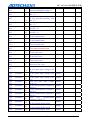
Coordinate
system and
pause
safety function
Memory
Pause(sec/microsecond)
G04 X/P_
coordinate system setting
G92
Auto coordinate system setting
Yes
software & hardware limit check
Yes
sudden stop
Yes
program storage capacity and quantity
Total capacity: 256M bytes; 9999
working areas; No processing
document limit
Insert,modification,delete,cancel
program edit
number,sequence,address, Yes
Program edit program
Character retrieving
decimal point programming
Yes
320×240lattice 5.7inch LCD
Display
Position screen/program edition
Cutter compensation/alarm display
Handwheel adjusting/diagnosis screen
Yes
Parameter setting/image emulation
M, S, T
function
Compensation
Function
Others function
assistant function
M Code
spindle function
S0-S15 (level control)
S15-S99999( analog)
Tool function
T Code
Memory for cutter compensation
18 sets of cutter length, radius
compensation.
Reverse gap compensation
Yes
Auto halving
Auto cutter calibrator
Yes
Designating arc radius R/central position Yes
Adtech CNC Co.,LTD
-8-
ADT-CNC4240 铣 床 数 控 系 统
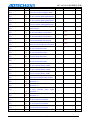
Electronic gear ratio
Yes
1.2 Working environments
Working voltage
24V DC(with filter)
Working temperature
0℃— 45℃
Best working temperature
5℃— 40℃
Working humidity
10%——90%no condensation
Best working humidity
20%——85%
Tempering storage
0℃—50℃
Humidity storage
10%——90%
Adtech CNC Co.,LTD
-9-
ADT-CNC4240 铣 床 数 控 系 统
2
2.1
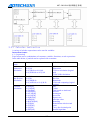
Hardware Interface Definition and Descriptions of Connection
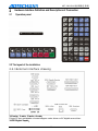
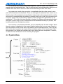
Operation panel
2.2 The layout of the installation
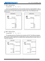
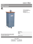
2.2.1 External interface drawing
1.X-axis、Y-axis、Z-axis、A-axis:
D type 15-core receptacle: connect stepper motor driver or AC digital servo driver.
2.XS5 Digital Input:
Adtech CNC Co.,LTD
- 10 -
ADT-CNC4240 铣 床 数 控 系 统
D type 25-core receptacle: shaft limitation and input signals of other switching value.
3.XS6 Digital Output:
D type 25-core receptacle: Output signal of switching value.
4.USB and serial interface: For file exchange between PC and CNC4240 controller and
for realizing other functions.
5.CNC4240 Controller: Using DC 24V, with power consumption of 5W.
6.XS7 Additional panel:
D type 15-core receptacle: connect handwheel.
7.XS8 Spindle:
D type 9-core receptacle: connect spindle transducer.
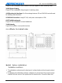
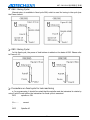
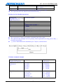
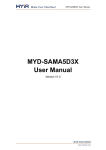
2.2.2 Plans to install size
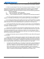
2.2.3
Notes installation
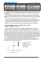
Installation conditions:
¾ The distribution cabinet must be dust proof, cooling liquid proof and organic solvent
proof.
¾ In designing the distribution cabinet, a distance of not less than 20cm must be kept
between the rear cover of the system and the machine box. It must be taken into
Adtech CNC Co.,LTD
- 11 -
ADT-CNC4240 铣 床 数 控 系 统
consideration that the temperature difference between inside and outside of the cabinet
shall not be more than 10°C when the temperature inside the cabinet rises.
¾ A fan shall be installed for the distribution cabinet so as to ensure the good ventilation
inside.
¾ The display panel shall be installed to a position which can’t be spilled by the coolant.
¾ In designing the distribution cabinet, it must be taken into consideration that the
external interference be lowered down as much as possible and interference be
prevented to be sent to the system.
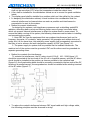
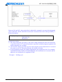
¾ Method to prevent interference:
In designing the systems, anti-interference measures such as shielding spatial EM
radiation, absorbing dash current and filtering clutter wave of power have been taken,
which can prevent external interferences to affect the system itself to some extent. To
ensure the stable running of the system, the following measures must be taken in installing
and connecting the system:
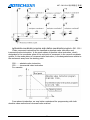
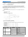
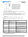
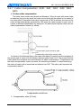
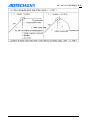
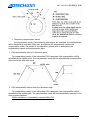
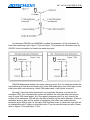
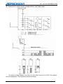
1. Keep CNC far from the equipment that can produce interferences (such as the
frequency converter, AC contactor, static generator, HV generator and section devices of
power line). At the same time, the switching power supply shall be separately connected to
the filter so as to enhance the anti-interference capacity of CNC (see Figure 1-4).
2. The power supply to system shall be provided via the isolated transformer. The
machine tool of the system must be grounded. CNC and the driver must be grounded via
separate grounding wires.
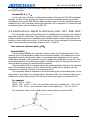
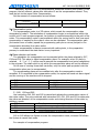
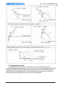
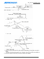
¾ Method to constrain the interference:
To restrain the interference, the RC return circuit (0.01μF,100~200Ω,figure 1-5)
should be connected at the two ends of the AC coil in a parallel manner, and this RC return
circuit should be installed to the position as close as possible to the inductive load
(figure1-6); the freewheeling diode should be reversely connected to the two ends of the DC
winding in a parallel manner; the surge absorber should be installed at the winding terminal
of the AC motor.(figure1-7)
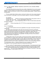
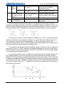
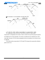
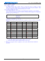
¾ To reduce the mutual interference between CNC signal cable and high-voltage cable,
the following principles must be observed in wiring:
Adtech CNC Co.,LTD
- 12 -
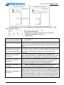
ADT-CNC4240 铣 床 数 控 系 统
Set
Cable type
Cabling requirements
Bind the cables of Group A to
Group B and C separately. The
further Group B is from Group C, the
better. Or, cables of Group A can be
shielded to avoid EM interference.
AC power line
A
Ac coil
Ac contactor
Ac coil(24VDC)
B
DC Relay(24VDC)
For cables between the System and
high-voltage distribution cabinet,
For cables between the System and milling
machine.
For cables between the System and Servo
motor driver.
position command cable
C
cable for cable enconder
Handwheel cable
Other shielded cables.
Adtech CNC Co.,LTD
- 13 -
Group B and A should be
bounded separately or Group B be
shielded. The further Group B is from
Group C, the better.
Group C and A should be
bounded separately or Group C be
shielded. A distance of at least 10cm
should be kept between Group C and
B and twisted-pair cables be used.
ADT-CNC4240 铣 床 数 控 系 统
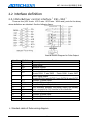
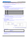
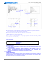
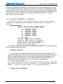
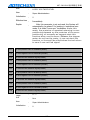
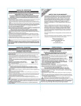
2.2 Interface definition
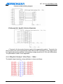
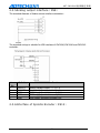
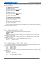
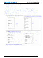
2.3.1 Motor&driver control interface ( XS1..XS4 )
There are four (XS1 X-axis、XS2 Y-axis、XS3 Z-axis、XS4 A-axis) ports for the driver,
whose definitions are identical. See the following figure.
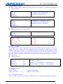
Internal Electric Diagram for Pulse Output.
Line No.
1
2
3
4
Definition
PU+
PUDR+
DR-
5
ALM
6
OUT
7
8
9
10
11
12
13
14
15
ECZ+
ECZPUCOM
24V+
24VECA+
ECAECB+
ECB-
Function
pulse signal+
pulse signaldirection signal+
direction signalServo alarm signal input
X-axis: IN34、Y-axis: IN35 、Z-axis: IN36、A-axis: IN37
Servo signal output
X-axis:OUT24 Y-axis:OUT25 Z-axis:OUT26 A-axis:OUT27
Encoder Z-phase input+
Encoder Z-phase inputused for single-end input driver.
The internally provided 24V power supply has already
been connected to 24V terminal of the controller.
Encoder A-phase input+
Encoder A-phase inputEncoder B-phase input+
Encoder B-phase input-
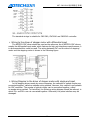
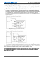
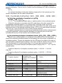
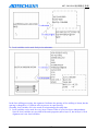
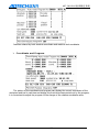
¾ Standard cable of Pulse wiring diagram
Adtech CNC Co.,LTD
- 14 -
ADT-CNC4240 铣 床 数 控 系 统
The standard wirings is suitable for CNC4340, CNC4240 and CNC4342 controller.
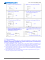
¾ Wiring to the driver of stepper motor with differential input
The ADTECH CNC driver should be used as the reference. As all ADTECH CNC drivers
employ the differential input mode, which features its high anti-interference performance, it
is recommended this mode be used. The wiring between CNC and the driver of stepping
motor and the stepping motor is shown in the following figure.
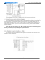
¾ Wiring Diagram to the driver of stepper motor with single-end input
In the stepping drivers made by some companies, the cathodes of optical coupler are
connected together, called co-cathode wiring method. However, this method is not suitable
for CNC controller. The anodes of optical coupler can be connected together, called
co-anode wiring method. To that effect, the following wiring diagram should be referred, in
which PU+ and DR+ are not connected together. Otherwise, the pulse interface may be
damaged.
Adtech CNC Co.,LTD
- 15 -
ADT-CNC4240 铣 床 数 控 系 统
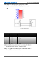
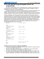
Wiring diagram to the driver of stepper motor with common anode input
¾ Connect to servo motor & driver diagram
As the differential wiring method is used in most cases, this method can be referred for
the pulse section. For many servo drivers that need the 12-24V power supply, the 24V
power supply provided by Pin 10 and 11 can be used. The actual wiring is subject to the
model of the servo driver. If you are not sure about the wiring, please contact ADTECH
without hesitation.
Note: Any two pins of PU+, PU-, DR+ and DR- cannot be connected together
directly, otherwise, it may damage the pulse interface.
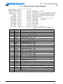
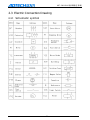
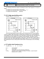
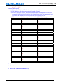
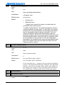
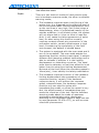
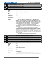
2.3.2 Digital input interface ( XS5 )
The numeric input port includes the limit signal of the hardware for each shaft. The
definition is shown as follows:
Adtech CNC Co.,LTD
- 16 -
ADT-CNC4240 铣 床 数 控 系 统
Line no
Interrupt No.
1
IN0
2
IN1
3
IN2
4
IN3
5
IN4
6
IN5
7
IN6
8
IN7
9
IN8
10
IN9
11
IN10
12
IN11
13
IN12
14
IN13
15
IN14
16
IN15
17
IN16(XLMT-)
18
IN17(XLMT+)
19
IN18(YLMT-)
20
IN19(YLMT+)
21
IN20(ZLMT-)
22
IN21(ZLMT+)
23
IN22(ALMT-)
24
IN23(ALMT+)
25
INCOM
Function
X-axis zero
Y-axis zero
Z-axis zero
A-axis zero
Cutter calibrator position check
Safe signal check input
System voltage alarm input
spare input
spare input
spare input
System feed alarm input
spare input
spare input
spare input
spare input
spare input
X-axis negative limit(standby IN32)
X-axis positive limit(standby IN33)
Y-axis negative limit(standby IN34)
Y-axis positive limit(standby IN35)
Z-axis negative limit(standby IN36)
Z-axis positive limit(standby IN37)
Z-axis positive limit(standby IN37)
A-axis positive limit(standby IN39)
INCOM(24+ 、 12V+)Input public interface access
provided by internal or external power supply
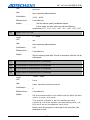
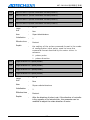
The digital input concise internal circuit
Adtech CNC Co.,LTD
- 17 -
ADT-CNC4240 铣 床 数 控 系 统
Photoelectric Switch Wiring Diagram
+Terminal is for the anode of power supply of the approaching switch, -Terminal is for
the grounding wire of the approaching switch and the OUT terminal is for the output signal.
For regular approaching switches, the operating voltage should be 10-30V, with NPN output.
The photoelectric switch is also applicable.
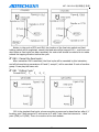
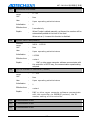
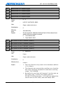
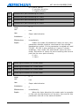
2.3.3 Digital Output Interface ( XS6 )
The digital output interface,.wiring definition is shown as follows:
Adtech CNC Co.,LTD
- 18 -
ADT-CNC4240 铣 床 数 控 系 统
Line
No.
1
2
3
4
5
6
7
8
9
10
11
12
13
14
15
16
17
18
19
20
21
22
23
24
25
Adtech CNC Co.,LTD
Definition
OUT0
OUT1
OUT2
OUT3
OUT4
OUT5
OUT6
OUT7
OUT8
OUT9
OUT10
OUT11
OUT12
OUT13
OUT14
OUT15
OUT16
OUT17
OUT18
OUT19
OUT20
OUT21
OUT22
OUT23
Function
spindle clockwise (M03)
spindle full clockwise (M04)
spare output (M56、M57)
Output spare (M58、M59)
cooling (M08、M09)
lubricating (M32、M33)
Output spare (M10、M11)
System timing oil pump
Output spare (M12、M13)
Output spare (M14、M15)
Output spare (M16、M17)
Output spare (M18、M19)
Output spare (M40、M41)
Output spare (M42、M43)
Output spare (M44、M45)
Output spare (M46、M47)
Output spare (M48、M49)
Output spare (M50、M51)
warning lights
running lights
Frequency-converting segment rate switch 3(M66、M67)
Frequency-converting segment rate switch 32(M64、M65)
Frequency-converting segment rate switch 31(M62、M63)
Frequency-converting segment rate switch 30(M60、M61)
OUTGND12V-、24V- External output of public power
- 19 -
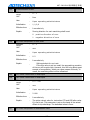
ADT-CNC4240 铣 床 数 控 系 统
Concise internal circuit(left)
Wiring diagram of machine(right)(take spindle on CW)
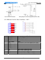
2.3.4 Manual Control Box Interface ( XS7 )
1
9
2
10
3
11
4
12
5
13
6
14
7
15
8
IN24
IN25
IN26
IN27
IN28
IN29
IN30
IN31
IN32
IN33
HA
HB
24V5V5V+
Line NO.
Definite
1
(IN24) Stall switch
2
(IN26) Stall switch
3
(IN28) Stall switch
4
(IN30) button
5
(IN32) button
7
24V9
(IN25) axis select
10
(IN27) axis select
11
(IN29) axis select
12
(IN31) axis select
13
(IN33)button
6
HA
14
HB
15
5V8
+5V
7
24V-
Adtech CNC Co.,LTD
Function
0.1 stall--- High-speed
0.01 stall--- Middle-speed
0.001 stall--- Low-speed
Reset circulation
Pause
24V provided by the internal negative power supply
X-axis
Y-axis
Z-axis
A-axis
Stop
Hand encoder A phase signal input
Hand encoder B phase signal input
Negative pole of internal 5V power supply
Positive pole of internal 5V power supply
Negative pole of internal 24V power supply
- 20 -
ADT-CNC4240 铣 床 数 控 系 统
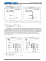
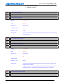
2.3.5 Analog output interface ( XS8 )
The standard diagram of Analog output interface connection:
The standard wirings is suitable for XS8 interface of CNC4340,CNC4240 and CNC4342
controller.
Line
No.
1
2
3
4
5
Definition
DAOUT1
DAOUT2
GND
GND
GND
Function
Analog voltage output(0~10)V
Analog voltage output(0~10)V
GND supply provided internally 24V
GND supply provided internally 24V
GND supply provided internally 24V
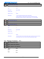
2.3.6 Interface of Spindle Encoder ( XS12 )
Adtech CNC Co.,LTD
- 21 -
ADT-CNC4240 铣 床 数 控 系 统
The standard wiring diagram of Spindle encoder:
The standard wirings of Spindle encoder is suitable for CNC4240 and CNC4342 controller.
Line
No.
Definition
1
2
3
4
5
6
7
8
9
ECA+
ECAECB+
ECBECZ+
ECZNC
NC
5V-
10
5V-
11
5V+
12
5V+
13
5V-
14
15
NC
NC
Adtech CNC Co.,LTD
Function
Encoder A phase input+
Encoder A phase inputEncoder B phase input+
Encoder B phase inputEncoder Z phase input+(standby)
Encoder Z phase input-(standby)
Non
Non
Negative pole of internal 5V power supply, cannot
external power supply
Negative pole of internal 5V power supply, cannot
external power supply
Positive pole of internal 5V power supply, cannot
external power supply
Positive pole of internal 5V power supply, cannot
external power supply
Negative pole of internal 5V power supply, cannot
external power supply
Non
Non
- 22 -
connect to
connect to
connect to
connect to
connect to
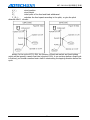
ADT-CNC4240 铣 床 数 控 系 统
¾ AB-phase decoding input has differential connection and common anode connection,
depending on the type of the encoder.
¾ Encoder output has the open collector output, complementation output, voltage output
and long-line driver output generally. It can use the common anode connection for the
open collector output, complementation output and voltage output, and use the
differential connection for the long-line driver output.
¾ As shown in the following figure, AB-phase decoding input signal uses the differential
connection; if use the common anode connection, it needs to connect the positive pole
of A-phase with the positive pole of B-phase together; if use the common cathode
connection, it needs to connect the negative pole of A-phase with the negative pole of
B-phase together.
Differential Connection (see as below):
5V power supply is provided externally.
Common Anode Connection (see as below):
The voltage of the power supply depends on the encoder, when using 5V power supply,
the resistance R is not required; when using 12V power supply, it can use 1K-2K resistance
for R; when using 24V power supply, it can use 2K-5K resistance for R.
It is suggested that use the encoder with the long-line driver output, as it uses
the differential connection, the anti-interference performance will be better
when the line is long.
Adtech CNC Co.,LTD
- 23 -
ADT-CNC4240 铣 床 数 控 系 统
2.3.7 RS232 Transmission interface ( XS9 )
Serial Communication Interface -9-Chip Signal Socket (male)
XS9
1
6
2
7
3
8
4
9
5
line No
1
2
3
4
5
6
7
8
9
Definition
NC
TXD
RXD
NC
GND
NC
NC
NC
NC
NC
NC
TXD
NC
RXD
NC
NC
NC
GND
Function
Non
Send Data
Receive Data
Non
GND
Non
Non
Non
Non
2.3.8 USB Memory interface to connect ( XS10 )
Standard USB memory interface(example of U disk);
2.3.9 PC USB Communication interface ( XS11 )
Standard USB communication interface;
Adtech CNC Co.,LTD
- 24 -
ADT-CNC4240 铣 床 数 控 系 统
2.3 Electric Connection Drawing
2.3.1 Schematic symbol
Adtech CNC Co.,LTD
- 25 -
ADT-CNC4240 铣 床 数 控 系 统
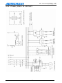
2.3.2 Power plans to connect
Adtech CNC Co.,LTD
- 26 -
ADT-CNC4240 铣 床 数 控 系 统
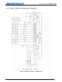
2.3.3 Servo Driver Connection Diagram
Adtech CNC Co.,LTD
- 27 -
ADT-CNC4240 铣 床 数 控 系 统
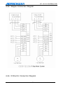
2.3.4 Stepper Connection Diagram
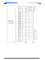
2.3.5 IO Electric Connection Diagram
Adtech CNC Co.,LTD
- 28 -
ADT-CNC4240 铣 床 数 控 系 统
Adtech CNC Co.,LTD
- 29 -
ADT-CNC4240 铣 床 数 控 系 统
Adtech CNC Co.,LTD
- 30 -
ADT-CNC4240 铣 床 数 控 系 统
Adtech CNC Co.,LTD
- 31 -
ADT-CNC4240 铣 床 数 控 系 统
3 G Code Program
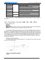
3.1 Basic knowledge of program
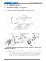
3.1.1 Motion direction and name of control axis
This system can control the fast moving for four axes. For feeding, it can control the
interpolation for three axes.
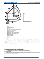
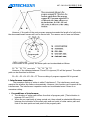
The definition of the axis direction, adopt Cartesian coordinate system, as follows, (in
the face of machine tool):
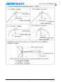
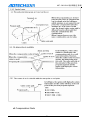
Z:
When you face the machine tool: The upward and downward movements of the
cutter relative to the workpiece is called the axis Z movement. The upward
movement of the cutter is called the positive-direction movement of axis Z,
whereas downward movement negative-direction movement of axis Z.
Adtech CNC Co.,LTD
- 32 -
ADT-CNC4240 铣 床 数 控 系 统
X:
The leftward and rightward movements of the cutter relative to the workpieve is
called the axis X movement. The leftward movement of the cutter is called the
negative -direction movement of axis X, whereas rightward movement
positive-direction movement of axis X.
Y:
The forward and backward movements of the cutter relative to the workpieve is
called the axis Y movement. The forward movement of the cutter is called the
positive-direction movement of axis Y, whereas backward movement
negative-direction movement of axis Y.
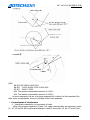
Main shaft: look down the workpiece, the clockwise rotation is the natural rotation of
the main shaft, anticlockwise is the opposite rotation.
A,B,C: the positive direction of the rotation coordinate axis is the positive directoin of
the X, Y, Z coordinate axis accordingly, according to the onward direction of the
right hand whorl to confirm.
Note: In this User’s Manual, the movements described on X, Y and Z axes refer to the
movement relative to the workpiece. In other words, a coordinate system is assumed for the
workpiece.
Adtech CNC Co.,LTD
- 33 -
ADT-CNC4240 铣 床 数 控 系 统
3.1.2 Machine tool coordinate system and workpiece
coordinate system ( G53 、 G54 ~ G599 )
1)Machine tool coordinate system
The coordinate system of this machine tool is a fixed one on it. The establishment of
this coordinate system is based on the operation each time the system returns to the
reference point after NC is electrified. To select the coordinate system of the machine tool,
G53 instruction is used.
2)Workpiece coordinate system
The workpiece coordinate system is used when the program is activated for machining,
for which some benchmark point is set as the origin. Normally, in the process of
programming, the programmers do not know where the workpiece is on the machine tool.
The workpieve programs they compiled often take some point on the workpieve as the
reference point. Therefore, the coordinate system set on the basis of this reference point is
called workpieve coordinate system. When the workpiece to be processed is fixed on the
machine tool, first the cutter will be moved to the designated reference point, and the
coordinate value of this point of the machine tool is set at the origin of the workpiece
coordinate system. Thus, when the system executes the machining programs, the cutter will
perform the machining actions by taking this workpiece coordinate system as its reference
object. For above reasons, the offset of the coordinate system’s origin is of great
significance for the CNC machine tools.
This System can be set with six workpieve coordinate systems (nine expansion
coordinate systems, ranging from G591 to G599, are added for the new version system). In
operation, the offset value of the coordinate system’s origin of each workpiece relative to
the origin of the machine tool’s coordinate system should be set. Then G5X (5X represents
the number of the actual workpieve coordinate system. It is same for the following part)
instruction is used to select them. G5X serves as the mode status instruction, respectively
corresponding to the pre-set workpieve coordinate systems ranging from 1#-6#.
Adtech CNC Co.,LTD
- 34 -
ADT-CNC4240 铣 床 数 控 系 统
3)Absolute coordinate program and relative coordinate program(G90、G91)
Cutter movement instructions are classified as absolute value instruction and
incremental value instruction. In the mode status of absolute value instruction, what’s
designated is the coordinate value of the end point of movement in the current coordinate
system; In the mode status of increment value instruction, is the designated axes relative to
the movement away from the starting point.
G90………absolute value instruction
G91………incremental value instruction
For example:
From above introduction, we may better understand the programming with both
absolute value method and increment value method.
Adtech CNC Co.,LTD
- 35 -
ADT-CNC4240 铣 床 数 控 系 统
3.1.3 The mode status function and the non-mode status
function
The mode status function means that once a code is designated in the current program
segment, it will be effective till another code of the same group in the program segment
appears. And if this instruction is used in the next program segment again, it doesn’t need to
be designated.
The non-mode status function means a code can function only in its program segment.
If this instruction is used again for the next program segment, it must be re-designated.
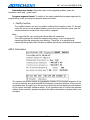
For example:
N0 G54 G0 X0 Y0;
(Select the workpiece coordinate system, fast position to X0 Y0)
N1 G01 X150. Y25. F100 ;(Linear interpolating to X150, Y25 )
N2 X50. Y75. F120; (Linear interpolating to X50, Y75. G01 is a mode status instruction
and can be omitted)
N3 X0;
(Linear interpolatig to X0, Y75. F120 is a mode status instruction and can be
omitted)
3.1.4 Feeding
The feed of CNC machine tool can be classified as two types: fast locating feed and
cutting feed.
The fast locating feed appears when G00, fast manual move and the movement
between fast feeding and locating in the fixed cycle are engaged. The speed of fast locating
feed is determined by the machine tool’s parameters. When this mode is used, the
movements of the axes engaged in the feeding are irrelevant to each other. These axes
move respectively at the rate set by the parameter. Normally, the locus of the cutter is
shaped as a fold line or straight line.
Cutting feed is used in the case of G01, G02 and 03 and when machining feed in fixed
cycle is involved. The speed of the cutting feed is determined by the address F, with its unit
as mm/min. In the machining program, F is the value of a mode status. In other words, the
originally programmed F value remains effective before the new F value is given. At the
beginning of time the CNC system is electrified, the F value is set by the system parameter.
The interpolation relation is remained between the axes engaged in feeding. The
combination of their movements become the cutting feed movement.
The max. value of F is determined by the system parameter. If the programmed F value
is greater than this value, this value will remain unchanged for the actual cutting feedrate.
The cutting feedrate can also be controlled by the switch of feed percentage on the
control panel. The actual cutting feedrate should be the product of the given F value and
feed percentage. The rate range is 10%-150%.
Adtech CNC Co.,LTD
- 36 -
ADT-CNC4240 铣 床 数 控 系 统
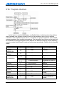
3.1.5 Program structure
In the text of a machining program, one English letter is called a instruction address
that’s followed by a numeric number to form the a instruction word. One or multiple
instruction word s suffixed by the mark “;” constitute one program segment. And multiple
program segments form a machining program. The instruction word serves as the basic unit
to constitute the program segment. Each address has different meaning, whose following
numeric number has different format and value range accordingly. Please refer to the table
below:
Function
program name
program
segment No.
Prepared to
function
Add
O
N
G
X,Y,Z
Size definition
R
I,J,K
feedrate
Spindle Speed
Select Cutter
Assistant
function
Cutter offset
number
Pause time
Designated
subprogram
Adtech CNC Co.,LTD
F
S
T
M
H,D
P,X
P
Range
1~9999
1~9999
Meaning
program number
Serial No.
00~99
NC designated function
±99999.999mm
Location coordinates
value
±99999.999mm
Radius, fillet radius
±9999.9999mm
Coordinate of center of
circle
feedrate
1~100,000mm/m
1~4000 rotate per minute Spindle Speed Value
Cutter No.
0~99
Assistant function of M
0~99
code
Designated cutter offset
1~200
number
Pause time(millisecond)
0~65 second
Invoke subprogram
1~9999
number
- 37 -
ADT-CNC4240 铣 床 数 控 系 统
number
The number of
repeat
Parameter
P,L
P,Q,R
1~999
P is 0~99999.999
Q is ±99999.999 mm
R is ±99999.999
Invoke subprogram
number
fixed cycle parameter
In addition, an optional number N × can be used at the beginning of a program
segment for identifying it. It must be noted that the execution order of program segment is
related only to the position in the memory where the program is saved, not to the program
segment number. In other words, even if the program segment numbered as N20 is in front
of the one numbered as N10, the one with the number of N20 will be executed earlier.
If the first character of some program segment is “/”, it means this is a conditional
program segment. That is to say, when the jump switch is at the upper position, this
program segment won’t be executed, whereas when the jump switch is at the lower
position, this program segment can be executed.
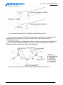
1)Main program and subprogram
The machining program consists of the main program and subprogram. Basically, NC
executes the instructions from the main program. When it executes a evoke instruction from
the subprogram, NC will change to execute the subprogram. It will return to the main
program when it executes the return instruction from the subprogram.
When the machining program needs to run the same locus for multiple times, we can
program this locus into a subprogram and save it in the program memory of the machine
tool. Then each time this locus is executed in the program, we can invoke the subprogram.
When a main program invokes a subprogram, this subprogram can also invoke another
subprogram. This is called dual nest of subprogram. A machine tool can allow a subprogram
of quadruple nest at maximum. When the subprogram instructions are invoked, the invoked
subprogram can be repeatedly executed through the instruction, with a max. repetition
number up to 999 times.
A subprogram should has the structure as below:
O××××;
subprogram number
…………;
…………;
subprogram contents
…………;
M99;
Return to main program
The program should begin with a subprogram number designated by address O. At the
end of the program, the instruction M99 for returning to main program must be included.
M99 may not be seen in a individual program segment. As the end of the subprogram, such
a program segment is acceptable:
G90 G00 X0 Y100. M99;
In the main program, the program segment that invokes the subprogram must include
the contents below:
M98 P×××××××;
Adtech CNC Co.,LTD
- 38 -
ADT-CNC4240 铣 床 数 控 系 统
Here, in the numbers following address P, the last four digits are used for designating
the number of the subprogram to be invoked, the front three digits for designating the
repeated times to be invoked.
M98 P51002; To invoke subprogram No.1002, repeat 5 times.
M98 P1002;
To invoke subprogram No.1002, repeat 1 times.
M98 P50004; To invoke subprogram No.4, repeat 5 times.
The invoke instruction can appear in the same program segment as the motion
instruction:
G90 G00 X−75. Y50. Z53. M98 P40035;
This program segment instructs axis X, Y and Y to move to the designated position with
the speed of fast locating feed, then invoke to execute subprogram No.35 for four times.
Unlike other M codes, when M98 and M99 are executed, no signal is sent to the side of
machine tool.
When NC can’t find out the program number designated by address P, the alarm will be
sent out.
The invoke instruction of subprogram—M98 can’t be executed under the MDI mode. If
a subprogram needs to be executed individually, you can edit the program in the
programming mode as follows and execute it in the auto running mode.
O×××;
M98 P××××;
M30;
2)Program finished
When the following codes are seen at the end of the program, it means the program
part is finished.
EIA
M30 CR
Define
The end of the program and return
to the beginning of the program
M99 CR
M99 LF
subprogram finished
In executing the program, if the abovementioned program-end code is detected, the
device will finish executing the program and the system will enter the reset state. In the
case of M30, CR or M30 LF, the system will return to the beginning of the program (in an
auto way). In the case of end of subprogram, the system will return to the program which
invokes the subprogram.
3)File finished
EIA
ER
ISO
M30 LF
ISO
%
Define
program finished
Remark: If ER(EIA) or %(ISO) is executed without M30 at the end of the program, CNC
will change to the reset state.
Adtech CNC Co.,LTD
- 39 -
ADT-CNC4240 铣 床 数 控 系 统
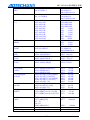
3.2 Preparatory Functions(G Code)
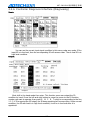
3.2.1 G Code of list
G Code
G00
G01
G02
G03
G04
G17
G18
G19
G20
G21
G28
G29
*G40
G41
G42
G43
G44
*G49
*G54
G55
G56
G57
G58
G59
G591
G592
G593
G594
G595
G596
G597
G598
G599
Set
01
00
02
06
00
07
08
05
G65
00
G73
G74
G76
*G80
G81
G82
09
Adtech CNC Co.,LTD
Function
Locate(fast move)
Linear interpolation (cut feed)
Arc-circle interpolation CW
Arc-circle interpolation CCW
Pause, Stop
XY plane selection
ZX plane selection
YZ plane selection
Input data of British system
Input data of metric system
Return to reference point
Return from reference point
Write-off of cutter radius compensation
Compensation of left cutter radius
Compensation of right cutter radius
Length of positive-direction cutter
Length of negative-direction cutter
Write-off of cutter length offset
Workpiece coordinate system 1
Workpiece coordinate system 2
Workpiece coordinate system 3
Workpiece coordinate system 4
Workpiece coordinate system 5
Workpiece coordinate system 6
Coordinate system of expansion workpiece 7
Coordinate system of expansion workpiece 8
Coordinate system of expansion workpiece 9
Coordinate system of expansion workpiece 10
Coordinate system of expansion workpiece 11
Coordinate system of expansion workpiece 12
Coordinate system of expansion workpiece 13
Coordinate system of expansion workpiece 14
Coordinate system of expansion workpiece 15
Macro program command (not developed for
4340, test version)
Fixed cycle for drilling and cutting deep holes
Fixed cycle for reverse-thread tapping
Fixed cycle for fine boring
Cancel fixed cycle
Fixed cycle for drilling and cutting
Fixed cycle for drilling and cutting
- 40 -
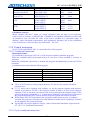
ADT-CNC4240 铣 床 数 控 系 统
G83
G84
G85
G86
G87
G88
G89
*G90
G91
G98
G99
03
10
Fixed cycle for drilling and cutting deep holes
Fixed cycle for tapping
Fixed cycle for boring and cutting
Fixed cycle for boring and cutting
Fixed cycle for reverse boring and cutting
Fixed cycle for boring and cutting
Fixed cycle for boring and cutting
Absolute value program
Incremental value program
Return to initial plane in fixed cycle
Return to R point plane in fixed cycle
Note: Items with “ * ” are the defaulted values of mode status for G codes of groups in
the system.
3.2.2 Interpolation Functions ( G00、 G01、 G02、 G03)
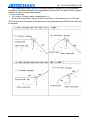
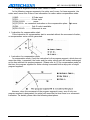
1)Fast locating(G00)
Format:
G00 X_Y_Z_;
X_Y_Z_:coordinate value, whether it is a absolute position value or incremental position
value will be determined by the mode status value of G90 or G91.
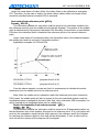
The instruction G00 allows each shaft to move to the designated position with the set
fast speed. The instructed shafts are irrelevant to each other. In other words, the locus of
the cutter is a straight line or fold line. The moving speed of each shaft under the instruction
G00: at axis X, Y and Z, the shaft will move according to the set parameter, and this speed
is not controlled by the current F value. When all shafts reach the end points, CNC will
consider that this program segment is finished and the system will change to execute the
next program segment.
Example of G00 programming:
The starting point is set as X and instruction as Y. The cutter will move to form the locus
as shown in the figure below.
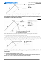
2)Linear interpolation(G01)
Format:
Adtech CNC Co.,LTD
- 41 -
ADT-CNC4240 铣 床 数 控 系 统
G01 X_Y_Z_F_;
:It refers to the coordinate value. It can be absolute or incremental value
X_Y_Z_
according to the current state of G90 or G91.
:It refers to the speed.
F
The instruction G01 allows the current interpolation mode status to be changed to
linear interpolation mode status. The cutter will move from the current position to IP
designated position, whose locus is a straight line. F- designates the speed with which the
cutter moves along the line, with its unit as mm/min.
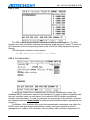
G01 for example:
Suppose the current cutter is at the point X-50. Y-75., the program segment is as
follows:
N1 G01 X150. Y25. F100 ;
N2 X50. Y75.;
Out of the tool will track as follows.
3)Arc-circle interpolation(G02/G03)
The instructions listed below can
In X-Y plane
G17 { G02 / G03 } X__ Y__ { (
In X-Z plane
G18 { G02 / G03 } X__ Z__ { (
In Y-Zplane
G19 { G02 / G03 } Y__ Z__ { (
No.
1
Content
select plane
enable the cutter to move along the arc locus:
I__ J__ ) / R__ } F__ ;
I__ K__ ) / R__ } F__ ;
J__ K__ ) / R__ } F__ ;
Command
G17
G18
G19
G02
2
Adtech CNC Co.,LTD
Arc direction
G03
- 42 -
Define
Designate the arc interpolation
on X-Y plane
Designate the arc interpolation
on Z-X plane
Designate the arc interpolation
on Y-Z plane
Arc interpolation of clockwise
direction
Arc interpolation of
counter-clockwise direction
ADT-CNC4240 铣 床 数 控 系 统
3
4
End
position
G90 mode
Two-axes instruction in
X, Y and Z
G91 mode
Two-axes instruction in
X, Y and Z
Two-axes instruction
in X, Y and Z
Distance between
the start point and
origin
Arc radius
5
Feed rate
Coordinate value of end position
in the current workpiece
coordinate system
Distance between the start
point and origin (with direction)
Distance between the start
point and origin (with direction)
Arc radius
speed of along-the-arc
movement
R
F
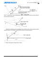
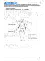
The arc direction mentioned here refers to the direction for which the XY plane is
viewed from the positive direction of Z axis to its negative direction. Similarly, for XY or YZ
plane, the observing direction should be from the positive direction of Y axis or X axis to its
negative direction (this is applicable for right-hand coordinate system, as shown below).
The end point of the arc is determined by the address X, Y and Z. In G90 mode status,
which is the absolute mode status, the address X, Y and Z tell the coordinate value of the
arc’s end point in the current coordinate system. In G91 mode status, which is the
incremental mode status, what X, Y and Z tell are the distances between the current point of
the cutter and the end point along the coordinate axes.
To X direction, the address I tells the distance between the point of current cutter and
the center of circle. To X and Y direction, the distance between the point of current cutter
and the center of circle is given the address J and K. The symbol of I, J and K are determined
by the respective movement direction.
To program a segment of arc, in addition to the method of given end point position and
circle center position, we can also use the given radius and end point position, and use
address R to tell the radius and replace the address of given circle center. The R value can
be positive and negative. Normally, a positive R value is used for programming a segment of
arc which is less than 180°, whereas a negative R value is used for programming a segment
of arc which is more than 180°. To program a whole circle, we have to use the method of
given center of the circle.
Adtech CNC Co.,LTD
- 43 -
ADT-CNC4240 铣 床 数 控 系 统
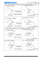
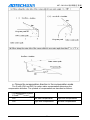
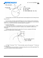
Use absolute value method and incremental value method respectively to program the
locus in the diagram.
(1) absolute value method
G00 X200.0 Y40.0 Z0 ;
G90 G03 X140.0 Y100.0 I-60.0 F300.0 ;
G02 X120.0 Y60.0 I-50.0 ;
or
G00 X200.0 Y40.0 Z0 ;
G90 G03 X140.0 Y100.0 R60.0 F300.0 ;
G02 X120.0 Y60.0 R50.0 ;
(2) incremental value method
G91 G03 X-60.0 Y60.0 I-60.0 F300.0 ;
G02 X-20.0 Y-40.0 I-50.0 ;
or
G91 G03 X-60.0 Y60.0 R60.0 F300.0 ;
G02 X-20.0 Y-40.0 R50.0 ;
Use F to designate the feedrate of arc interpolation, which is the cutter’s speed along
the tangent direction of the arc.
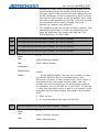
3.2.3 Pause Instruction ( G04 )
Function: To cause a pause between two program segments.
Format: G04 PG04 XAddress P tells the time of pause. When there is no decimal, the min. value of the
instruction is 0.001 second.
Address X tells the time of pause. When there is no decimal, the min. value of the
instruction is 1 second.
Example:G04 P 1000 : Pause 1000millisecond,as 1second.
G04 X 1 : Pause 1 second.
3.2.4 Select Plane ( G17 、 G18 、 G19 )
This group of instructions are used for the plane of selected arc interpolation and of
cutter radius compensation. The method is shown below:
G17………Select XY plane
G18………Select ZX plane
G19………Select YZ plane
G17, G18 and G19 are in the program segment without instruction, the plane remains
unchanged.
For example:
G18 X_ Z_ ;ZX plane
X_ Y_ ;No change plane (ZX plane)
Adtech CNC Co.,LTD
- 44 -
ADT-CNC4240 铣 床 数 控 系 统
In addition, the move instruction is irrelevant to the plane. For example, under the
following instruction, Z axis is not on XY plane, and the movement of Z axis is irrelevant to
XY plane.
G17 Z_ ;
For relevant instructions of the plan selection, please refer to the instructions of the
circular interpolation and the cutter compensation.
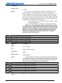
3.2.5 Coordinate Instruction( G53 ~ G59 、G591 ~ G599 、G92 )
1)Selecting coordinate of machine tool(G53)
Format: G53 X_Y_Z_;
X_Y_Z_:The absolute coordinate value or relative position in the coordinate system
When this instruction is executed under G90 mode status, the cutter moves to the
IP-designated coordinate position in the machine tool coordinate system at the fast
feedrate. When this instruction is executed under G91 mode status, the cutter moves at the
incremental value of the selected coordinate system. G53 is a non-mode status instruction.
That is to say, it can only function in the current program segment.
The distance between the zero of machine tool coordinate system and the reference point
is set bythe parameter. Unless otherwise stipulated, the reference point of each axis
coincides with the zero of the machine tool coordinate system.
2)Use presetting workpiece coordinate system(G54~G59,G591~G599)
Based on the mounted position of workpiece on the machine tool, this System can
provide six workpiece coordinate systems via presetting (the new version is expanded to 9
coordinate systems). Through the operations via the LCD panel, the offset of the origin of
each workpiece coordinate system relative to the origin of that for machine tool can be set.
Then the instruction G is used to select them. G is a mode status instruction, which
corresponds to the preset workpiece coordinate systems ranging from 1#~15#. See the
example below:
Preset the offset of 1# workpiece coordinate system:X-150.000 Y-210.000
Z-90.000。
Preset the offset of 4# workpiece coordinate system:X-430.000 Y-330.000
Z-120.000。
Coordinates value of
end point in the
Program segment
Define
machine tool coordinate
system
X-100, Y-160
Select 1# coordinate system, fast
N1 G90 G54 G00 X50. Y50.;
locating
Z-160
N2 Z-70.;
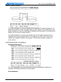
Z-160.5
N3 G01 Z-72.5 F100;
Linear interpolating, F value is 100
X-112.6
N4 X37.4;
(Linear interpolating)
Z-90
N5 G00 Z0;
Fast locating
X-150, Y-210
N6 X0 Y0 A0;
X0, Y0, Z0
Select to use machine tool
N7 G53 X0 Y0 Z0;
coordinate system
X-380, Y-280
N8 G57 X50. Y50. ;
Select 4# coordinate system
Adtech CNC Co.,LTD
- 45 -
ADT-CNC4240 铣 床 数 控 系 统
N9 Z-70.;
N10 G01 Z-72.5;
Z-190
Z-192.5
Linear interpolating, F value is 100
(mode status value)
X392.6
N11 X37.4;
Z-120
N12 G00 Z0;
X-430, Y-330
N13 G00 X0 Y0 ;
From above example, we can see that the role of G54-G59 is to move the origin of the
coordinate system NC uses to the point with the preset coordinate value in the machine tool
coordinate system. For the presetting method, please refer to the part describing operations
in this Manual.
Once the system returns to zero after started up, the workpiece coordinate systems
ranging from 1-6 will be established. G54 is the initial mode status at the time of electrifying.
The absolute position of the position image is the coordinate value of the current coordinate
system.
In the numeric control programming for the machine tools, the interpolation
instruction and other instructions related to the coordinate value refer to the coordinates
in the current coordinate system (the system when the instruction is executed), unless
otherwise stipulated. In most cases, the current coordinate system is the one from
G54-G59. It is a rare case that the machine tool coordinate system be used directly.
3)Programmable workpiece coordinate system(G92)
Format:(G90)G92 X_Y_Z_;
This instruction help establish a new workpiece coordinate system, in which the
coordinate of the current cutter’s point is the IP-designated value. G92 is non-mode status
instruction. However, the workpiece coordinate system established on the basis of this
instruction is of mode status nature. In reality, this instruction also gives a offset in a indirect
manner, which is the coordinate value of the origin of the new workpiece coordinate system
in the original coordinate system. From the performance of G92, we can see that this offset
is the difference between the coordinate value in the original system and the IP-designated
value. If G92 is used for many times, the offset provided each time G92 is used will be added
up. For each preset workpiece coordinate system (G54-G59), this added offset is effective.
The new coordinate system of the part is therefore established by using the
abovementioned instructions. For example, the coordinate value of the cutter tip can be IP-.
Once the coordinate is determined, the position of the absolute value instruction is the
coordinated value in this coordinate system.
Adtech CNC Co.,LTD
- 46 -
ADT-CNC4240 铣 床 数 控 系 统
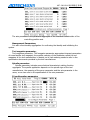
Use G92 X600.0 Z1200.0 ; Use instruction for setting the coordinate system (some
benchmark point on the hilt as the cutter start point)
Note: a. If G2 is used for setting the coordinate system in cutter offset, the coordinate
system set by G92 will be employed for the compensation of cutter length.
b. For compensation of cutter radius, cutter offset should be cancelled when G92 is
used.
For example:
Preset the offset of 1# workpiece coordinate system:X-150.000
Z-90.000。
Preset the offset of 4# workpiece coordinate system:X-430.000
Z-120.000。
Program segment
content
In the end of the machine
tool coordinate system of
coordinates
N1 G90 G54 G00 X0
X-150, Y-210, Z-90
Y0 Z0;
N2 G92 X70. Y100.
Z50.;
X-150, Y-210, Z-90
N3 G00 X0 Y0 Z0;
X-220, Y-310, Z-140
N4 G57 X0 Y0 Z0;
X-500, Y-430, Z-170
N5 X70. Y100.
Z50.;
X-430, Y-330, Z-120
Y-330.000
Define
Select 1# coordinate system and fast
position to origin of coordinate system.
Don’t move the cutter, and establish the
new coordinate system, in which the
current point has the following coordinate
values: X70, Y100, Z50. Fast position to
new origin of coordinate system.
fast position to new origin of coordinate
system.
Select 4# coordinate system and fast
position to origin of coordinate system.
(already offset)
fast position to primary origin of
coordinate system.
4)Local coordinate system(G52)
Adtech CNC Co.,LTD
Y-210.000
- 47 -
ADT-CNC4240 铣 床 数 控 系 统
G52 can establish a local coordinate system, which equals to the sub-coordinate system
in G54-G59 system.
Format:G52 X_Y_Z_;
In this instruction, IP-gives an offset which equals to the current G54-G59 coordinate
systems. In other words, IP-gives the origin of the local coordinate system the position
coordinate in the current G54-G59 coordinate systems, even if a local coordinate system is
established by a G52 instruction before the instruction G52 is executed. To cancel the local
coordinate system, you can simply use G52 IP0.
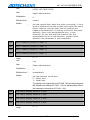
3.2.6 Instructions related to reference point( G27 、G28 、G29 )
The coordinate system of the machine tool is established by returning to the reference
point each time NC is electrified. The reference point is fixed on the machine tool, whose
position is determined by the installation place of baffle switch of each shaft and the zero
position of each shaft’s servo motor. In this machine tool, the coordinates of the reference
point in the machine tool coordinate system are X0, Y0 and Z0.
Auto return to reference point(G28)
Format:G28 IP_;
This instruction enables the instruction shaft to return to the reference point of the
machine tool via IP-designated middle point at the fast feedrate. The middle point can be
designated by either the absolute value or incremental value, depending on the current
mode status. Basically, this instruction is used to enable the workpiece to move out of the
processing area after the machining program is finished so that the finished parts can be
removed and the parts to be machined can be loaded.
When instruction G28 is executed before the system manually returns to the reference
point, the movement direction of each shaft from the middle point is positive, like the
movement for manually returning to the reference point.
The coordinate value of instruction G28 will be saved by NC as the middle point. On the
other hand, if one shaft is not included within instruction G28, the coordinate value of the
middle point of this shaft saved by NC will the previous value given by instruction G28.
For example:
N0010 X20.0 Y54.0;
N0020 G28 X-40.0 Y-25.0; the coordinate value of the middle poin(-40.0,-25.0)
N0030 G28 Z31.0; the coordinate value of the middle poin(-40.0,-25.0,31.0)
The coordinate value of this middle point is mainly used by instruction G29.
Adtech CNC Co.,LTD
- 48 -
ADT-CNC4240 铣 床 数 控 系 统
)Notes:
Under the mode status of cutter offset, the cutter offset is also effective to instruction
G27. Therefore, for the sake of safety, the cutter offset (radius offset and length offset)
should be cancelled before instruction G28 is executed.
Auto return from reference point(G29)
Format:G29 IP-;
This instruction enables the instruction shaft to move to the instruction position from
the reference point through the middle point at the fast feedrate. The position of the middle
point is determined by the previous instruction G28. Normally, this instruction is used behind
G28 when the instructed shaft is located at the reference point or the second reference
point.
Under mode status of incremental value, the instruction value is the distance between
the middle point and the end point (instruction position).
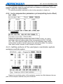
Application examples for G28 and G29.
G28 X1300.0 Y700.0 ;
………………………
G29 X1800.0 Y300.0 ;
(program from A to B)
(program from B to C)
From the above example, we can see that it is unnecessary to calculate the actual
movement from the middle point to the reference point .
Note: After the middle point is passed to reach the reference point when instruction
G28 is used, the middle point will also be moved to the new coordinate system once the
coordinate system is changed for the part. After that, when instruction G29 is executed, it is
will be located at the designated place via the middle point.
Return for inspection from reference point (G27)
Format:G27 IP_;
This instruction enables the instruction shaft to move to the IP-designated position at
the fast feedrate, then check whether this point is the reference point. If so, the system will
send out the completion signal that this shaft returns to the reference point (the indicator
for reaching the reference point by this shaft will be illuminated). If not, an alarm will be
sent out and the running of the program will be stopped.
Adtech CNC Co.,LTD
- 49 -
ADT-CNC4240 铣 床 数 控 系 统
3.2.7 Cutter Compensation ( G40 、 G41 、 G42 、 G43 、 G44 、
G49 )
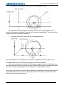
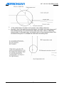
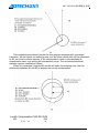
1)Cutter radius compensation
The cutter has a certain size (length and diameter). When the part with some shape
is machined, the locus by which the cutter moves along will be subject to the nature of
the cutter itself. If the data of the cutter’s size are set in CNC in advance, the locus of the
cutter will be automatically generated by CNC when the same program is used, even if
cutters of different specification are employed. The data concerning the cutter size are
called compensation amount (or offset).
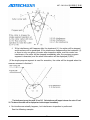
As shown in the following figure, the cutter with radius R is used to cut the workpiece A,
the central path of cutter is B, the distance between path B and A is R. The process that the
cutter leaves the workpiece A for some distance is called “compensation”. Programmers use
the radius compensation mode to produce the machining programs. In actual machining,
the radius of cutter will be measured and entered into CNC. The cutter path becomes the
compensation path B.
2)Compensation value (D Code)
Adtech CNC Co.,LTD
- 50 -
ADT-CNC4240 铣 床 数 控 系 统
Maximally, eighteen D00-D18 compensation values can be set in this System. In the
program, the two numeric values after instruction D are the compensation amount. They
must be set via the menu Cutter Compensation.
Set the amount of compensation are as follows:
Mm input
compensation value
Inch input
0-±999.999mm
0-±999.999inch
3)Compensation vector
The compensation vector is of 2D nature, which equals the compensation value
designated by code D. The calculation of compensation vector is accomplished within the
control unit. In each program segment, its direction is modified according to the path of the
cutter. This compensation vector is accomplished within the control unit so that how much
compensation is needed for the cutter’s move can be calculated. The compensation path
(the central locus of cutter) equals the programming path plus or minus (subject to the
compensation direction) the cutter radius.
Vector compensation is always concerned with cutting tools, in the preparation
process, to understand the state vector is very important.
4)Plane selection and vector
The calculation for compensation can be executed within the plane selected by G17,
G18 and G19. This plane is called compensation plane. For example, when XY plane is
selected, (X,Y)or(I,J)will be used to execute the compensation and vector calculations
in the program. The shaft which is not within the compensation plane will not be affected.
In the case of running three-shaft controller, only the cutter path projected onto the
compensation plane can be compensated.
The compensation plane can be modified only after the compensation mode is
cancelled. If it is modified in the compensation mode, the system will send out alarm signal
and the running of the machine will be stopped.
G Code
G17
G18
G19
compensation plane
X-Y plane
Z-X plane
Y-Z plane
5)G40,G41 and G42
Use instruction G40, G41 and G42 to cancel and activate the compensation vector of
the cutter radius. They are combined with instruction G00, G01, G02 and G03 to determine
the value and direction of the compensation vector and moving direction of the cutter by
defining a mode.
G Code
Function
G40
cancle the compensation of the cutter radius.
G41
left compensation of the cutter radius.
G42
right compensation of the cutter radius.
G41 or G42 allows the System to enter the compensation mode, whereas G40 allows
the System to cancel that mode.
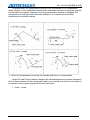
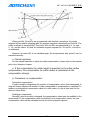
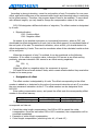
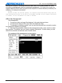
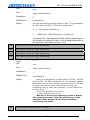
For example of compensation program:
Adtech CNC Co.,LTD
- 51 -
ADT-CNC4240 铣 床 数 控 系 统
6
4
30
5
.0
0
4
R
40.0
40
3
7
20
2
Y
R20
8
20
10
1
11
X
9
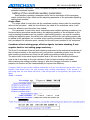
O0007 ;
G0G40G49G80G90;
G0 X0 Y0;
N1 G91 G17 G00 G41 Y20.00 D07 ;
N2 G01 Y40.00 F25.00:
N3 X40.00 Y30.00:
N4 G02 X40.00 Y-40.00 R40.00:
N5 X-20.00 Y-20.00 R20.00:
N6 G01 X-60.00:
N7 G40 Y-20.00:
N8 M30
%
Program segment (1) is used for start-up. In this program segment, instruction G41
changes the compensation canceling mode to compensating mode. At the end of this
segment, the cutter center makes compensations by allowing the cutter radius to be vertical
to the path direction of next program. The compensation value of cutter is designated by
D07. That is to say, the compensation number is set as 7. G41 refers to the left
compensation of cutter path.
6)Details of cutter radius compensation C
This part provides details of cutter radius compensation C.
a.Cancel mode
When the System is electrified/reset/executes instruction M02 and M30, the System will
be in the cutter compensation mode.
Adtech CNC Co.,LTD
- 52 -
ADT-CNC4240 铣 床 数 控 系 统
The vector must be 0 in compensation mode, and the path of cutter center is consistent with
programming path. The compensation mode G40 must be designated before the program is
finished.
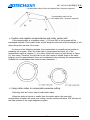
b. Compensation Start
In cancel mode, the System will enter the compensation mode when the program
segment that satisfies the following conditions is executed:
¾ Containing instruction G41 or G42, or the control section enters G41 or G42 mode.
¾ Offset number of cutter compensation is not zero.
¾ For movement of any axis (except I, J and K) on the instruction compensation plane, the
movement value can’t be zero.
The program segment of compensation start should not have the arc instruction G02
and G03. Otherwise, the alarm (P/S34) will be activated. In compensation start segment,
two program segments will be read. One is read and executed and the other enters the
cutter compensation buffering area.
Under single program segment method, the second program segment is read and the
first program segment is executed, and then stopped.
In continuous execution, normally two program segments are read in advance.
Therefore, three program segments are available within CNC. One is the program segment
being executed, and the next two program segments enter the buffering area
Note: In the descriptions below, the frequently seen terms, “inner side” and “outer
side”, are defined as: when the inclination of intersection of two moving program segments
equals or greater than 180°, it is called “inner side”, whereas the inclination is 0-180°, it is
called “outer side” (see the following figures):
Adtech CNC Co.,LTD
- 53 -
ADT-CNC4240 铣 床 数 控 系 统
Adtech CNC Co.,LTD
- 54 -
ADT-CNC4240 铣 床 数 控 系 统
C. Compensation mode
In compensation mode, if two or over two non-moving instructions are not
consecutively designated (auxiliary function, pause, etc.), the compensation mode will be
executed correctly. Otherwise, the part may be excessively cut or insufficiently cut. In
executing the compensation mode, the compensation plane should not be modified.
Otherwise, the alarm signal will be sent out and cutter stopped.
Adtech CNC Co.,LTD
- 55 -
ADT-CNC4240 铣 床 数 控 系 统
Adtech CNC Co.,LTD
- 56 -
ADT-CNC4240 铣 床 数 控 系 统
Adtech CNC Co.,LTD
- 57 -
ADT-CNC4240 铣 床 数 控 系 统
d. Compensation Mode
Adtech CNC Co.,LTD
- 58 -
ADT-CNC4240 铣 床 数 控 系 统
In compensation mode, when the program segment satisfying any of the following
conditions, the System will enter the compensation cancel mode. The action of this program
segment is called “compensation cancel”.
¾ Instruction G40
¾ The number of cutter radius compensation is 0.
When the compensation cancel mode is executed, the instructions for arc (G03 and
G02) can’t be used. Otherwise, the instruction arc will generate alarm (P/S34) and cutter will
be stopped.
Adtech CNC Co.,LTD
- 59 -
ADT-CNC4240 铣 床 数 控 系 统
e. Change the compensation direction in the compensation mode
The G code (G41 and G42) for cutter radius compensation determines the
compensation direction. The symbols of compensation are described as follows:
compensation symbol
G Code
G41
left side compensation
right side compensation
G42
right side compensation
left side compensation
Adtech CNC Co.,LTD
- 60 -
ADT-CNC4240 铣 床 数 控 系 统
In special cases, the compensation direction can be modified in the compensation
mode. However, such modification should not be executed in the start-up program segment
and its follow-up program segments. Once the compensation direction is changed, the
concept of inner and outer sides becomes ineffective. It is assumed the following
compensation are positive values.
¾ When the compensation is carried out normally and there is no intersection
When G41 and G42 are used for changing the offset direction from program segment A
to B, if the intersection of the compensation path is not needed, the vector can be made to
be vertical to the program segment B from B’s start point.
linear----linear
Adtech CNC Co.,LTD
- 61 -
ADT-CNC4240 铣 床 数 控 系 统
linear----arc
arc----arc
¾ When the cutter center path for cutter radius compensation is more than one circle in
length
Normally, this phenomenon won’t occur. However, when G41 and G42 are modified, or
I, J and K are used to instruct G40, the above situation may appear.
Adtech CNC Co.,LTD
- 62 -
ADT-CNC4240 铣 床 数 控 系 统
f. Temporary compensation cancel
In compensation mode, if the following instructions are executed, the compensation
will be temporarily cancelled. After that, the System will automatically resume the
compensation mode. For details of this operation, please refer to descriptions on
compensation cancel and compensation start.
¾ G28 automatically returns to reference point
In compensation mode, if the instruction G28 is executed, the compensation will be
cancelled at the middle point. The compensation mode will be automatically resumed after
returning to the reference point.
¾ G29 automatically returns from the reference origin
In compensation mode, if the instruction G29 is executed, the compensation will be
cancelled at the middle point. The compensation mode will be automatically resumed in the
next program segment.
When instruction is immediately executed after G28.
Adtech CNC Co.,LTD
- 63 -
ADT-CNC4240 铣 床 数 控 系 统
When instruction is not immediately executed after G28.
g. G code for cutter radius compensation in compensation mode
In compensation mode, when the G code (G41 and G42) for cutter radius
compensation is designated, there will be a vector vertical to the previous program segment
and relative to the moving direction. This vector is irrelevant to the machining inner and
outer sides. However, if this G code is designated in the arc instructions, the correct arc can’t
be obtained.
If the cutter radius compensation G (G41 and G42) changes its compensation direction,
please refer to (5).
Adtech CNC Co.,LTD
- 64 -
ADT-CNC4240 铣 床 数 控 系 统
h. Instruction temporarily cancelling compensation vector
In compensation mode, if G92 (absolute coordinate programming) is designated, the
compensation vector will be temporarily cancelled. After that, this vector will be
automatically resumed.
At the time, unlike the compensation mode, the cutter will move from the intersection
to the point which cancels the compensation vector. Once the compensation mode is
resumed, the cutter will directly move to the intersection.
Adtech CNC Co.,LTD
- 65 -
ADT-CNC4240 铣 床 数 控 系 统
i. Program segment where cuter doesn’t move
In the following program segments, the cutter won’t move. In these segments, the
cutter won’t move even if there is an intersection for cutter radius compensation mode.
(1)M05:………………… M Code input
(2)S21:………………… S Code input
(3)G04 X10000:………
pause
(4)(G17)Z100:no movement instruction on the compensation plane
(5)G90:………………… Only G code is available.
(6)G01 G91 X0:…………Movement is zero.
Not move.
¾ Instruction for compensation start
If the instruction for compensation start is executed without the movement of cutter,
no compensation vector will be generated.
¾ Instruction for compensation mode
In compensation mode, if only the instruction for the program segment, which does not
move the cutter, is executed, the vector and the cutter center path will remain unchanged
as the time without this program segment. (Please refer to (3) for compensation mode) at
the time, the program segment for cutter moving is executed at the stop point of single
program segment.
However, when the movement of the program segment is zero, even if only one
program segment is designated, the cutter will move like the time there is no movement
instruction. For details, please refer the following descriptions.
Adtech CNC Co.,LTD
- 66 -
ADT-CNC4240 铣 床 数 控 系 统
Two program segments without cutter movement can’t be executed consecutively. If
executed in that way, a vector, which takes the length as the compensation value and
whose direction is vertical to the movement direction of the previous program segment, will
be generated. This will lead to over-cutting.
Note: SSS indicates the program segments are used for operating the cutter thrice.
¾ Instruction at the same time as compensation cancel
When the program segment is executed at the same time as compensation cancel but
without cutter movement, a vector, which takes the length as the compensation value and
whose direction is vertical to the movement direction of the previous program segment, will
be generated. This vector will be cancelled at the next movement instruction.
j. On the compensation plane, this program segment include G40 and I—J—K
instructions.
¾ Previous program segment as G41 or G42
At the time, suppose that CNC sends out the instruction that a movement along the
direction of I, J or K is made from the previous program segment.
Adtech CNC Co.,LTD
- 67 -
ADT-CNC4240 铣 床 数 控 系 统
Note: The obtaining of cutter intersection by CNC is irrelevant to the inner and outer sides of
the designated machining.
When the intersection can’t be obtained, the end point cutter of the previous program
segment moves to the position vertical to the previous program segment.
¾ Cutter center path is longer than a circle.
Adtech CNC Co.,LTD
- 68 -
ADT-CNC4240 铣 床 数 控 系 统
In above figure, the cutter center path doesn’t move along the circle, but along the arc
from P1 to P2.
In some cases, the alarm signal (P/S41)may be sent out because of the interference
inspection. The related explanation will be followed up. (If it is expected to move along the
circle, the arc instructions must be executed segment by segment.)
k. Corner Movement
If more than two vectors are generated at the end of the program segment, in other
words, the cutter moves from one vector to another, this movement is called corner
movement.
If these vectors almost have the same value, the corner movement will not be
executed. The latter vector can be ignored.
If △VX≤△V limit and △VZ≤ △V limit, the latter vector will be ignored. △V limit uses
the parameter.
If these vectors are inconsistent, a movement along the corner will be generated. This
movement belongs the latter program segment.
Adtech CNC Co.,LTD
- 69 -
ADT-CNC4240 铣 床 数 控 系 统
However, if the path of the next program segment exceeds the length of a half circle,
the abovementioned process will not be carried out. The reasons can be seen as follows:
If the vector is not ignored, the cutter path can be described as follows:
P0→P1→P2→P3(arc-circle)→P4→P5→P6→P7
However, if the distance between P2 and P3 is ignored, P3 will be ignored. The cutter
path can be described as follows:
P0→P1→P2→P4→P5→P6→P7 The arc cutting of program segment N6 is ignored.
l. Interference inspection
The excessive cutting of cutter is called “interference”. The interference mode can
examine the whether the cutter cut excessively. However, this function can’t inspect all the
interferences. The interference inspection mode can be activated even if there is no
excessive cutting.
¾ Preconditions of interference:
The direction of cutter path differs from that of program path. (The inclination is
between 90° and 270°).
When the arc machining is being carried out, there should a substantial difference
between the inclination of the start point and end point of cutter center path and
that of the start point and end point of the program path.
Adtech CNC Co.,LTD
- 70 -
ADT-CNC4240 铣 床 数 控 系 统
(G41)
N5 G01 G91 X8000 Y2000 D01;
N6 G02 Y-1600 X3200 12000 J-8000 D02;
N7 G01 X2000 Y-5000:
(H01 Tool radius compensation amount r1=2000)
(H02 Tool radius compensation amount r2=6000)
In above examples, the arc of program segment N6 is within the first quadrant. But
after cutter compensation, the arc is located in the fourth quadrant.
¾ Pretreatment of interference
Interference caused by the movement of vetor
When the program segment A, B and C for cutter compensation are executed, vector
V1, V2, V3 and V4 will be generated between A and B, and vector V5, V6, V7 and V8 will
Adtech CNC Co.,LTD
- 71 -
ADT-CNC4240 铣 床 数 控 系 统
generated between B and C. The closest vector should be inspected. If there is an
interference, it will be automatically eliminated. If the vector to be ignored is located at the
last part of the corner, the interferences can’t be eliminated.
Interference inspection:
Between V4 and V5—interference—V4, V5 eliminated
Between V3 and V6—interference—V3, V6 eliminated
Between V2 and V7—interference—V2, V7 eliminated
Between V1 and V8—interference—V1, V8 can’t be eliminated
In inspecting, if some vector has no interference, the follow-up vectors won’t be
inspected. If the program segment B is of arc movement, the vector interference will cause
linear movement.
(Example 1) Cutter’s linear movement from V1 to V8
(Example 2) Cutter’s linear movement is send as follows:
Cutter path: V1→V2→VY→V8
Adtech CNC Co.,LTD
- 72 -
ADT-CNC4240 铣 床 数 控 系 统
If the interference still happens after the treatment (1), the cutter will be stopped
and the alarm will be generated. If the interference happens after the treatment (1)
or there is only one group of vector after inspection starts, and this vector has
interference, the cutter will be stopped immediately after the previous program
segment is executed, and the alarm information will be displayed (P/S41)
(If the single program segment is used for execution, the cutter will be stopped when the
program segment is finished.)
The interference ignores the vector V2 and V5. But interference will happen between the vector V1 and
V6. The alarm information will be displayed and cutter stopped immediately.
¾ No interference actually happens., but interference inspection is performed.
See the following example:
Adtech CNC Co.,LTD
- 73 -
ADT-CNC4240 铣 床 数 控 系 统
The depth of the concave is less than the compensation value.
No interference actually happens. However, as it is the program segment B, the
direction of program is opposite to the path of the radius compensation. The cutter will be
stopped and alarm information displayed.
The depth of groove is less than the compensation value
Like the example (1), the direction of cutter path is opposite to that of program path
m.Compensation can’t be conducted by entering instruction from MDI
During the automatic running of the NC program made by absolute instructions, when
the single segment is used for temporary stop, after the MDI operation is interpolated and
the auto running is started again, the cutter path can be described as follows:
At the time, the vector of the next program segment is transmitted, and other vectors will be
generated according to the next two program segments. Therefore, compensation after
point Pc can be performed correctly.
Adtech CNC Co.,LTD
- 74 -
ADT-CNC4240 铣 床 数 控 系 统
When point Pa, Pb and Pc are programmed with absolute instructions, the single
segment will be used for stopping after the program segment is executed from Pa to Pb. The
cutter is moved by inserting MDI. The vector Vb1 and Vb2 are transmitted to V‵b1 and
V‵b2, and the vector Vc1 and Vc2 between program segment Pb→Pc and Pc→Pd will be
re-calculated.
However, as vector Vb2 is not calculate again, the compensation after point Pc can be
executed correctly.
n. Manual operation
For the manual operation in cutter tip radius compensation, please refer to the manual
part in the Operation chapter.
o. If the compensation for cutter length is executed in the cutter radius
compensation, the compensation for cutter radius is considered as the
compensation change.
p. Precautions on compensation
Instruction compensation
D code is used for designating the number of compensation value. Once designated, H
code will remain effective till another H code is designated or compensation is cancelled. In
addition to designating compensation value for cutter radius, H code is also used for the
value of cutter offset.
Modifying compensation
Normally, when the cutter is changed, the compensation value must be modified in the
cancel mode. If the compensation value is modified in the compensation mode, the new
compensation value will be calculated at the end of the program segment.
Adtech CNC Co.,LTD
- 75 -
ADT-CNC4240 铣 床 数 控 系 统
¾ Positive and negative compensations and cutter center path
If the compensation is a negative value (-), G41 and G42 in the program will be
exchanged mutually. If the cutter center moves along the outer side of the workpiece, it will
move along the inner side. Vice versa.
As shown in the following example, the compensation is normally set as positive in
preparing the program. When the cutter path is programmed as Figure (a), if the
compensation value is negative (-), the cutter center will move in a path shown in Figure
(b). Vice versa. Therefore, the part can be cut into a male or female shape in the same
program, and the gaps between them can be adjusted by the selecting the compensation.
(Suitable for compensation start and the type A canceling. )
¾ Using cutter radius to compensate excessive cutting
Machining with arc’s inner side of small cutter radius
When the radius of corner is smaller than the cutter radius, the inner side
compensation of cutter will cause over cutting, and the system will alarm. CNC will stop at
the start position of the single-segment program.
Adtech CNC Co.,LTD
- 76 -
ADT-CNC4240 铣 床 数 控 系 统
Groove machining with size smaller than cutter radius
As the cutter center path is forced to move reversely to the program path due to the
cutter radius compensation, over-cutting will occur.
Segment-difference machining with size smaller than cutter radius
If there is segment difference smaller than the cutter radius in the program, and this
segment difference is machined by the arc instruction, the cutter center path as normally
compensated will have the direction opposite to that of the program. At the time, the
compensated vector is ignored and the cutter moves to the second vector in a linear fashion.
The execution of single-segment program stops here. If the machining is not conducted
under the single-segment mode, the auto running will continue. If the segment difference is
a straight line, no alarm signal will be sent out and the cutting be correct. However, the
uncut part will remain.
Adtech CNC Co.,LTD
- 77 -
ADT-CNC4240 铣 床 数 控 系 统
If the initial vector of cutter is not ignored, over-cutting will occur.
Normally, when the machining process begins, the cutter will move along axis Z
some distance away from the workpiece after the cutter radius is effectively
compensated. In aforesaid case, you should refer to the procedure below if the
movement along axis Z is divided into fast feed and cutting feed:
Adtech CNC Co.,LTD
- 78 -
ADT-CNC4240 铣 床 数 控 系 统
If the selected plane doesn’t include the two program segments with movement
instruction, N6 can’t enter the buffering area, and the cutter center path will be calculated
by N1, as shown in above drawing. If the compensation vector is not calculated at
compensation start, over-cutting will consequently occur. Thus the abovementioned
example must be modified as follows:
When N1 is executed, program N2 and N3 will enter the buffering area. Use the
relationship between N1 and N2 to execute the correct compensation.
Length Compensation G43 G44 G49
G43
Adtech CNC Co.,LTD
Z_H_
or
G43
H_
- 79 -
ADT-CNC4240 铣 床 数 控 系 统
G44
G44
According to above instruction, move the end position of axis Z instruction for one more
offset, and set the difference of the assumed cutter length and the actual value in machining
to the offset memory. Therefore, the program doesn’t need to be modified. To use cutters
with different lengths, you only need to change the compensation value of the cutter.
G43, G44 designate a different direction of migration, The offset number is designated
by H code.
¾ Migrate direction
G43:Positive offset
G44:Negative offset
No matter it is a absolute instruction or incremental instruction, when at G43, you
should add the offset designated by H code (set in the offset memory) to coordinate value of
the end point of the axis Z’s movement instruction; when at G44, you should deduct the
offset designated by H code. Then use the coordinate value of the calculated results as that
of the end point.
When the movement of axis Z is omitted, it can be considered as the following
instruction. If the offset is a positive value, instruction G43 serves as an offset moving
positively, whereas instruction G44 serves as an offset moving negatively.
G43
G91 H_
G44
When the offset is a negative value, the movement is reverse.
G43 and G44 are of mode status G code, which remain effective before they meet other
G code in the same group.
¾ Designation of offset
The offset number is designated by H code. The offset corresponding to the offset
number is added to or deducted by the value of movement instruction at axis Z to produce
the new movement instruction at axis Z. The offset number can be designated from
H00-H18.
Enter cutter compensation menu, and preset the offset onto the corresponding offset
number in the offset memory.
Mm input
Inch input
Offset
0~±999.999
0~±99.9999
The offset number 00 means the corresponding offset of H00 is 0. The offset H00
corresponds can’t be set.
¾ Cancel the cutter length compensation; Use G49 or H00 to cancel the cutter
compensation. Once the instruction G49 or H00 is executed, the compensation will be
cancelled immediately.
¾ Examples of cutter length compensation.
¾ Cutter length compensation (machining hole #1, #2 and #3 ).
Adtech CNC Co.,LTD
- 80 -
ADT-CNC4240 铣 床 数 控 系 统
N1 G91 G00 X120.0 Y80.0:…………………(1)
N2 G43 Z-32.0 H01:……………………… (2)
N3 G01 Z-21.0:…………………………… (3)
N4 G04 P2000:…………………………… (4)
N5 G00 Z21.0:…………………………… (5)
N6 X30.0 Y-50.0:………………………… (6)
N7 G01 Z-41.0:…………………………… (7)
N8 G00 Z41.0:…………………………… (8)
N9 X50.0 Y30.0:………………………… (9)
N10 G01 Z-25.0:………………………… (10)
N11 G04 P2000:………………………… (11)
N12 G00 Z57.0 H00:……………………… (12)
N13 X-200.0 Y-60.0:……………………… (13)
N14 M30:
Note: When the offset number is changed to modify the offset, it only means
the offset becomes a new one. It does not mean that the new offset is added to
the old one.
H01………………………Offset 20.0
H02………………………Offset 30.0
G90 G43 Z100 0 H01………Z Moves to 120.0
G90 G43 Z100 0 H02………Z Moves to 130.0
3.2.8
Hole machining cycle ( G73 ~ G89 )
If the fixed cycle function for hole machining is used, the functions, which are
accomplished by several program segments if other methods are involved, can be
Adtech CNC Co.,LTD
- 81 -
ADT-CNC4240 铣 床 数 控 系 统
performed within one program segment. The Table 7.1 provides all fixed cycles for hole
machining. Basically, to accomplish one fixed hole machining cycle, the following six
procedures should be performed:
1. Fast locating of axis X and Y.
2. Fast locating axis Z to point R.
3. Hole machining.
4. Action at hole bottom.
5. Axis Z returns to point R.
6. Axis Z fast returns to initial point.
Table 7.1
G Code
G73
G80
G81
G82
G83
G84
G85
G86
G88
G89
Fixed Hole Machining Cycle
Returning
Machining
Action at hole
(positive
(negative direction
Application
bottom
direction at axis
at axis Z)
Z)
Time by time,
Fast locating
High-speed
-
cutting feed
feed
deep hole
drilling
Canceling fixed
-
-
-
cycle
cutting feed
Fast locating
Regular drilling
-
feed
cycle
cutting feed
Pause
Fast locating
Drilling or
feed
coarse boring
Time by time,
Fast locating
Deep-hole
-
cutting feed
feed
drilling cycle
cutting feed
Pause—Spindle on cutting feed
Right-thread
CCW
tapping
cutting feed
cutting feed
Boring cycle
-
cutting feed
Spindle off
Fast locating
Boring cycle
feed
cutting feed
Pause—Spindle off Manual
Boring cycle
cutting feed
Pause
cutting feed
Boring cycle
Adtech CNC Co.,LTD
- 82 -
ADT-CNC4240 铣 床 数 控 系 统
he instruction G90/G91 and G98/G99 can affect the execution of the instruction for
fixed hole machining cycle. Figure 7.2(a) and Figure 7.2(b) shows the influence posed by
G90/G91 to the instruction for fixed hole machining cycle.
G98/G99 determines whether the cutter returns to point R or the initial point after the
hole machining is finished in the fixed cycle. Under G98 mode status, axis Z will return to the
initial point after hole machining. Under G99 mode status, it will return to point R.
Normally, if the hole being machined is on a perfectly flat plane, we can use the
instruction G99. This is because the system will position the next hole after returning to
point R under G99 mode status. As in the regular programs point R is very close to the
surface of the workpiece, G99 will save the time of machining the parts. However, if there is
protruded areas or bars on the surface of workpiece, the cutter may collide with the
workpiece when G99 is used. In this case, G98 should be used, by which the next hole will
be located after axis Z returns to the initial point. Thus this practice could be safer. Please
refer to Figure 7.3(a) and Figure 7.3(b).
Adtech CNC Co.,LTD
- 83 -
ADT-CNC4240 铣 床 数 控 系 统
The parameters of hole to be machined are provided after G73/G74/G76/G81~G89,
with format as follows:
G××X___ Y___ Z___ R___ Q___ P___ F___
K___;
G××
: Hole machining method
X___ Y___ Z___
:Parameters for position of the hole to be machined
R___ Q___ P___ F___ : Machining parameter of the hole
K___
: Repeat times
Hole machining method: G
See Table 7.1
Parameters for position of
When the position of the hole to be machined is designated
the hole to be machined: by incremental or absolute value method, the locus by which the
X, Y
cutter moves along the hole and cutter’s speed are the same as
G00.
The position of the hole bottom along axis Z is designated
Parameters for position of by absolute value method, whereas the distance between point
the hole to be machined: Z R and the hole bottom is designated by incremental value
method.
The position of point R along axis Z is designated by
Machining parameter of
absolute value method, whereas the distance between the initial
the hole: R
point and point R is designated by incremental value method.
Used for designating the feed of each time in the deep-hole
Machining parameter of drilling cycle G73 and G83, and the offset in fine boring cycle
the hole: Q
G76 and reverse boring cycle G87 (always incremental
instruction, regardless of G90 or G91 mode status)
Machining parameter of
Used for designating the pause time in the fixed cycle
the hole: P
where the hole bottom has pause, with unit as second.
Used for designating the cutting feedrate in the fixed cycle.
In the fixed cycle, the movement from the initial point to point R
and point R to initial point is carried out at the fast feedrate, and
Machining parameter of
movement from point R to point Z is carried out at the cutting
the hole: F
feedrate designated by F. However, the movement from point Z
to point Z can be carried out either at the rate designated by F or
at the fast feedrate, depending on the nature of the fixed cycle.
Adtech CNC Co.,LTD
- 84 -
ADT-CNC4240 铣 床 数 控 系 统
Repeat times: K
Used for designating the repeat times of the fixed cycled at
the current locating point. If K is not executed, NC will consider
K=1. If K=0, there will be no execution at the current point in
the fixed cycle.
As the hole machining designated by G×× is of the mode status, the current mode
status will remain unchanged if it not is modified or the fixed cycle is not cancelled. The fixed
cycle can be canceled by using G80 or instruction G of group 01. The machining parameter
of the hoe is of the mode status too, and it will also remain unchanged before it is modified
or the fixed cycle is canceled, even if the mode status for hole machining is changed. Any
machining parameter of the hole can be designated or modified when a fixed cycle is
instructed or at any time the fixed cycle is executed. The repeat times are not a value of
mode status, and it is only provided when repetition is needed. The feedrate is a value of
mode status, which will exist even if the fixed cycle is canceled. If NC system is reset in the
process of executing a fixed cycle, the mode status of hole machining, machining parameter
of the hole and repeat times will all be canceled.
The following example will help you better understand the aforesaid contents:
Item Program content
Notes
No.
S____ M03
Provide the rotation speed and instruct the spindle to
1
rotate in positive direction.
G81X__Y__Z__R__F
Fast position to the designated points of X and Y, and
__K__
machine the part according to the parameters provided by Z,
R and F and with the method provided by G81. Then repeat
2
the process for K times. At the beginning of executing the
fixed cycle, Z, R and F are the necessary machining
parameters of the hole.
Y__
Axis X remains unmoved, and axis Y is fast located to
instructed point for machining. The hole machining parameter
3
and method the keep the mode status value as 2. K value of 2
is ineffective here.
G82X__P__K__
Hole machining method is modified, and hole machining
parameter Z, R and F keep their respective mode status
4
values. Provide the value of hole machining parameter P and
designate to repeat K times.
G80X__Y__
Fixed cycle is canceled, and all hole machining
5
parameters are canceled except F.
G85X__Y__Z__R__P
As the fixed cycle is canceled when 5 is executed, the
__
necessary hole machining parameters, except F, must be
6
provided again, even if these parameters are unchanged
when compared to the original values.
X__Z__
Axis X is located to the instructed point for machining the
7
hole. The hole machining parameter Z is modified in this
program segment.
G89X__Y__
Position to XY’s instructed point for hole machining. The
8
hole machining method is modified as G98. R and P are
designated by 6 and Z by 7.
Adtech CNC Co.,LTD
- 85 -
ADT-CNC4240 铣 床 数 控 系 统
9
G01X__Y__
The mode status of fixed cycle is canceled. All hole
machining parameters, except F, are canceled.
The following methods are used for indicating the feed of each segment in the figures
below:
To indicate the movement with the fast feerate: ――→
To indicate the movement with the cutting feerate: →
To indicate the manual feed:
¾ G73(High-speed drilling cycle)
Format:G73 X_ Y_ Z_ R_ Q_ F_
In the high-speed drilling cycle for deep holes, the feed from R to Z is accomplished
section by section. After each section of cutting feed is finished, axis Z will lift upward for
some distance, then the cutting feed of the next section will be performed. The distance d,
by which the axis Z lifts upward, is provided by 531# parameter. The depth of feed is
provided by the hole machining parameter Q each time. This fixed cycle is mainly used for
machining holes with small radius-depth ratio (likeΦ5, depth of 70). The action that axis Z
lifts upward each time the cutting feed of each section is finished plays a role of breaking
chips.
¾ G74(Back whorl tapping cycle)
Format G74 X_
X_Y_:
Z_:
R_:
F_(D_):
Adtech CNC Co.,LTD
Y_
Z_
R_
F_(D_)
whorl position
whorl depth
initial point of the feed and feed withdrawal
calculate the feed speed according to the pitch, or give the pitch
distance with D_ directly.
- 86 -
ADT-CNC4240 铣 床 数 控 系 统
Notice: in the cycle of G74 and G84, the function of the feed rate switch and feed
holding switch will be neglected, namely the feed rate will be keep at 100%, and it can not
stop before a fixed cycle has been executed, the main shaft should be ordered to to rotate
around the tapping direction before the cycle.
¾ G80(Cancel the fixed cycle)
After instruction G80 is executed, the fixed cycle will be canceled by this instruction,
and all hole machining parameters of R and Z, except F, will be canceled. G code of another
group 01 can play the same role.
¾ G81(Drilling Cycle)
Format G81 X_
Y_
Z_
R_
F_
G81 is the simplest fixed cycle, whose execution process can be described as: after X, Y
locating, axis Z fast moves to R, and moves to Z with F rate, then fast returns to initial
point (G98) or R (G99). There is no action at the hole bottom.
Adtech CNC Co.,LTD
- 87 -
ADT-CNC4240 铣 床 数 控 系 统
¾ G82(Drilling cycle,Boring cycle)
Format G82 X_
Y_
Z_
R_
P_F_
The fixed cycle of G82 has an action of pause at the hole bottom. Other procedures are
the same as G81. The pause at the hole bottom can improve the precision on hole’s depth.
¾ G83(Deep-hole Drilling Cycle)
Format G83 X_
Y_
Z_
R_
Q_
F_
Similar to G73, under instruction G83, the feed from R to Z is also accomplished section
by section. Unlike G73, axis Z returns to R after the feed of one section is finished. Then it
moves at fast feedrate to the position, which keeps a distance of d to the start point of the
next feed section, and starts the movement for the feed of next section. The feed distance
for each section is given by the machining parameter Q, which is a positive value
permanently. The vale of d is provided by the parameters of 532#machine tool. Please
refer to Figure 8.9:
¾ G84(Tapping Cycle)
Format G84 X_
Adtech CNC Co.,LTD
Y_
Z_
R_
F_(D_)
- 88 -
ADT-CNC4240 铣 床 数 控 系 统
X_Y_:
whorl position
Z_:
whorl depth
R_:
initial point of the feed and feed withdrawal
F_(D_):
calculate the feed speed according to the pitch, or give the pitch
distance with D_ directly.
Notice: In the cycle of G74, G84, the function of feed rate switch and feed holding
switch will be ignored, namely feed rate is kept at 100%, it can not stop before a fixed cycle
is finished, you should command main shaft to rotate along the tapping direction before the
cycle.
Adtech CNC Co.,LTD
- 89 -
ADT-CNC4240 铣 床 数 控 系 统
7)G85(Boring Cycle)
Format G85 X_
Y_
Z_
R_
F_
This is a very simple fixed cycle, whose execution process can be described as: after X,
Y locating, axis Z fast moves to R, and moves to point Z with rate designated by F, then fast
returns to R. If it is under G98 mode status, it will fast return to the initial point after
returning to R.
¾ G86(Boring Cycle)
Format G86 X_
Y_
Z_
R_
F_
The execution process of this fixed cycle is similar with G81. The difference between
them is that in G86 the spindle will be stopped after the cutter moves to the hole bottom. It
will make the spindle rotate with the original direction and speed after the cutter returns to
R and the initial point.
Adtech CNC Co.,LTD
- 90 -
ADT-CNC4240 铣 床 数 控 系 统
¾ G88(Boring Cycle)
Manual return is available in fixed cycle G88, which is used for boring in the cycle (see
the Figure below):
¾ G89(Boring Cycle)
In this fixed cycle, the pause of hole bottom is added on the basis of G85. Please refer
to Figure 8.15:
¾ Precautions on fixed cycle for hole machining
a. In programming, it should be noted that the spindle must be instructed to rotate by
using S and M code before the instruction for fixed cycle is executed.
M03 ; spindle on CW
.
.
G□□…… ; correct
.
.
M05 ; Spindle off
Adtech CNC Co.,LTD
- 91 -
ADT-CNC4240 铣 床 数 控 系 统
G□□……;Incorrect (instruction M03 or M04 is needed before this program segment)
b. Under the mode status of fixed cycle, the program segment including X, Y, Z and R
will execute the fixed cycle. If a program segment doesn’t include any of the aforesaid
addresses, this program will not execute the fixed cycle, except the address X in G04.
Besides, the address P in G04 will not change the P value in the hole machining parameters.
;
(hole not machined)
F__; (hole not machined, F value upgraded)
M__; (hole not machined, only execute auxiliary functions)
G04 P__;(hole not machined, use G04 P_ to change the hole machining parameter P)
c. The hole machining parameter Q and P must be designated in the executed program
segment in the fixed cycle. Otherwise, the instructed Q and P values will be ineffective.
d. In executing the fixed cycle with spindle control (such as G76 and G84), the spindle
may have not reached the instructed speed when the cutter starts cutting. In this case, the
pause instruction G04 should be added between the operations for hole machining.
e. As we have discussed, the G code in group 01 can also play a role of cancelling the
fixed cycle. Therefore, the instruction for fixed cycle and the G code of group 01 should not
be written in the same program.
f. If an M code is instructed in the program for executing the fixed cycle, this M code
will simultaneously executed as the fixed cycle. The signal that indicates that the instruction
M has been executed will be sent out after axis Z returns to R or the initial point. When
parameter K is used for repeatedly executing the fixed cycle, the M code will be executed at
the first time the fixed cycle is executed.
g. Under the fixed cycle mode, the instruction G45-G48 for cutter offset will be ignored
(not executed).
h. When the switch for single program segment is set at the upper position, the fixed
cycle will stop after axis X and Y locating, fast feeding to R and returning from hole bottom
(to R or initial point). In other words, to complete the machining on one hole, the start-up
button for cycle needs to pressed thrice. In these three stops, the first two keep the system
to be in feed hold state, and the last one make the system to be in stop state.
i.
In executing G74 and G84 cycles, if the button for feed hold is pressed between the
two steps, namely axis Z moves from point R to point Z and moves from point Z to
point R, the indicator for feed hold will be illuminated immediately. However, the
action of the machine tool won’t be stopped immediately, and only when axis Z
returns to R can the system enter the feed hold state. In addition, in the G74 and G84
cycles, the switch for feed percentage is ineffective and it remains 100%.
Adtech CNC Co.,LTD
- 92 -
ADT-CNC4240 铣 床 数 控 系 统
¾ Example for cutter length compensation and fixed cycle
The value of offset number 11 is 200.0, of 15 is 190.0 and of 31 is 150.0. The offsets
are set respectively. The program is shown as follows:
Adtech CNC Co.,LTD
- 93 -
ADT-CNC4240 铣 床 数 控 系 统
N001 G92 X0 Y0 Z0 ;
set the reference point of coordinate system.
N002 G90 G00 Z250.0 T11 M6; change cutter.
N003 G43 Z0 H11 ;
At the initial point, cutter length compensation oF plane.
N004 S30 M3 ;
Spindle starts up.
N005 G99 G81 X400.0 Y-350.0
Z-153.0 R-97.0 F120.0 ; Machine hole #1 after locating.
N006 Y-550.0 ;
Machine hole #2 after locating, return to plane of R.
N007 G98 Y-750.0 ;Machine hole #3 after locating, return to plane of initial point.
N008 G99 X1200.0 ;
Machine hole #4 after locating, return to plane of R.
;
N009 Y-550.0
Machine hole #5 after locating, return to plane of R.
N010 G98 Y-350.0 ;Machine hole #6 after locating, return to plane of initial point.
N011 G00 X0 Y0 M5 ;
Return to reference point, spindle off.
N012 G49 Z250.0 T15 M6 ; Cancel cutter length compensation, change cutter.
N013 G43 Z0 H15 ; On the plane of initial point, cutter length compensation.
N014 S20 M3 ;
Spindle starts up.
N015 G99 G82 X550.0 Y-450.0 ;
Z-130.0 R-97.0 P30 F70; Machine hole #7 after locating, return to plane of R.
N016 G98 Y-650.0 ; Machine hole #8 after locating, return to plane of initial point.
N017 G99 X1050.0 ;
Machine hole #9 after locating, return to plane of R.
N018 G98 Y-450.0 ; Machine hole #10 after locating, return to plane of initial point.
N019 G00 X0 Y0 M5 ;
Return to reference point, spindle off.
N020 G49 Z250.0 T31 M6 ; Cancel cutter length compensation, change cutter.
N021 G43 Z0 H31 ; Cutter length compensation at the plane of initial point.
N022 S10 M3 ;
Spindle starts up.
N023 G85 G99 X800.0 Y-350.0 ;
Z-153.0 R47.0 F50 ;Machine hole #11 after locating, return to plane of R.
N024 G91 Y-200.0 ; Machine hole #12 and #13 after locating, return to plane of R.
Y-200.0 ;
N025 G00 G90 X0 Y0 M5 ; Return to reference point, spindle off.
N026 G49 Z0 ;
Cancel cutter length compensation.
N027 M30 ;%
Program stop.
3.3 Assistant Function(M,S,T)
In this System, S code is used for programming the spindle speed, T code for cutter
selection, and other programmable miscellaneous functions are realized via M code.
3.3.1 M Code
M Code List:
Adtech CNC Co.,LTD
- 94 -
ADT-CNC4240 铣 床 数 控 系 统
M Code
M01
M03
M04
M05
M06
M08
M09
M32
M33
M30
M98
M99
M56
M57
M58
M59
M10
M11
M20
M21
M12
M13
M14
M15
M16
M17
M18
M19
M40
M41
M42
M43
M44
M45
M46
M47
M48
M49
M50
M51
M66
M67
M64
M65
M62
M63
Adtech CNC Co.,LTD
Function
Program stop
Spindle on CW
Spindle on CCW
Spindle stop
Change cutter command
Open cooling
Close cooling
lubrication open
lubrication close
Program finished and return to program header
Invoke subprogram
Subprogram finished and return/repeated execution
Output NO.2 interrupt port is high electric level
Output NO.2 interrupt port is low electric level
Output NO.3 interrupt port is high electric level
Output NO.3 interrupt port is low electric level
Output NO.6 interrupt port is high electric level
Output NO.6 interrupt port is high electric level
Output NO.7 interrupt port is high electric level
Output NO.7 interrupt port is low electric level
Output NO.8 interrupt port is high electric level
Output NO.8 interrupt port is low electric level
Output NO.9 interrupt port is high electric level
Output NO.9 interrupt port is low electric level
Output NO.10 interrupt port is high electric level
Output NO.10 interrupt port is low electric level
Output NO.11 interrupt port is high electric level
Output NO.11 interrupt port is low electric level
Output NO.12 interrupt port is high electric level
Output NO.12 interrupt port is low electric level
Output NO.13 interrupt port is high electric level
Output NO.13 interrupt port is low electric level
Output NO.14 interrupt port is high electric level
Output NO.14 interrupt port is low electric level
Output NO.15 interrupt port is high electric level
Output NO.15 interrupt port is low electric level
Output NO.16 interrupt port is high electric level
Output NO.16interrupt port is low electric level
Output NO.17 interrupt port is high electric level
Output NO.17 interrupt port is low electric level
Output NO.20 interrupt port is high electric level
Output NO.20 interrupt port is low electric level
Output NO.21 interrupt port is high electric level
Output NO.21 interrupt port is low electric level
Output NO.22 interrupt port is high electric level
Output NO.22 interrupt port is low electric level
- 95 -
ADT-CNC4240 铣 床 数 控 系 统
M60
M61
M88 Pn Lm
M89 Pn Lm Qt
Output NO.23 interrupt port is high electric level
Output NO.23 interrupt port is low electric level
Inspect waiting input IO(IN n)whether the level signal m(high
or low)
Output OUT n, level is m,t millisecond delay to output
In machine tools, the roles of M code can be classified as two types: One is used for
controlling the execution of the program and the other is used for controlling the action
execution of the spindle, ATC device, cooling system and other auxiliary equipment.
Used M codes for program control
The M codes for program control include M00, M30, M98 and M99, whose functions are
respectively described as follows:
M00………Program stop. When NC receives M100, the program execution will be
interrupted. The program execution will be resumed after resetting and pressing start-up
button.
M30………Program end, and return to program header.
M98………Invoke subprogram.
M99………Subprogram end, and return to main program.
Other M Code
M03………spindle on cw. Use this instruction to allow the spindle to rotate
counter-clockwise at the current designated speed (CWW).
M04………Spindle on cww. Use this instruction to allow the spindle to rotate clockwise
at the current designated speed (CW).
M05………spindle stop.
M06………Change cutter. M06 T02 is used for changing to cutter 2#.
M08………open cooling.
M09………close cooling.
M32………lubrication open.
M33………lubrication close.
M88………specified input IO to carry out level judgement, continue carrying out if it is
the same or wait always. If the level signal is not specified, then default it as low level signal.
For instance, M88 P0 L1 waiting INO is high level, of wait always.
M89………specify output IO as the specified level judgement, if there is no specified
level signal, default is as the low level, if the Q value is specified, then this operation should
has Q millisecond delay before output the IO signal. For instance, M89 P5 L0, specify OUT5
output low level.
Notice:
z
when the move instruction and M is in the same programm segment, then the M instruction will be carried out
preferentially.
z
If there are more than one M code in the program, then there is only one is in effect, that is the last defined M code
is in effect.
3.3.2 S Code
The speed of spindle is sent out via S code, which is of the mode status. In other words,
it will remain effective after the speed is set till the mode status value of another S code
changes.
Adtech CNC Co.,LTD
- 96 -
ADT-CNC4240 铣 床 数 控 系 统
The maximum value of the S instruction is limited by the main shaft maximum rotation
speed of the parameter P5.020
The S instruction has three kinds of output mode, they are limited by the parameter
P2.049(axis number of the main shaft specified interface ), P1.061(frequency conversion
control mode ), as follows:
Set the P2.049 as nonzero value:
It means current main shaft is the AB phase pulse control mode, then the S value is
depending on the setting of the main shaft coder to decide the pulse frequency.
Set the P2.049 as nonzero value,set the P2.061 as 1:
The control mode of frequency conversion gear position and the communication of the
frequency conversion, utilize four IO ora(OUT23~OUT20)gear position. Four gear position
consist of sixteen coding, namely the S instruction value is S00~S15.
Set the P2.049 as nonzero value, set p2.061 as 0:
The control mode of frequency conversion analog, according to the ratio between S
value and the maximum rotation speed of parameter p5.020 then time 10v, get the
simulation voltage should be output; The MO3 or MO4 should be executed after the S
instruction has been specified, then output the analog.
3.3.3 T Code
The random selection mode is adopted in the cutter warehouse of this machine tool.
That is to say, the two-digit T code—T ×× will be used for designating the cutter
number, regardless of which sheath the cutter is in. The value of T in the address can
be any integer from 1-99.
0Warning:
The cutter table must be set correctly. If the contents in the table are inconsistent with
the reality, the machine tool will be severely damaged and unpredicted consequences
may occur.
3.4 Macro
3.3.4 Variable command
All address values in the program are replaced with variables instead of being described with fixed
values. Refers to variables when the program is running to improve the versatility of the program.
This function is called as variable command.
Instruction format:
# △ △ △ =○○○○○○○○○or # △ △ △ = [expression]
Detailed description
(1) Variable representation:
(a) # m ......
(b) # [f]……
Adtech CNC Co.,LTD
Values constituted with
M=0~9
f has the following
meanings
Value m
Variable
Expression
- (symbol) expression
- 97 -
#100
123
#543
#110 + #119
- #120
ADT-CNC4240 铣 床 数 控 系 统
Function expression
z
z
z
z
SIN [#110]
Standard arithmetic operators are +, -, × and /.
The function can not be executed when the function expression is omitted
The variable number can not be negative, such as # -100 is illegal
The following are incorrect representations of the variables:
False
#6/2
# - [#1]
#――5
→
→
→
Correct
#[6/2]
#[-#1]
#[-[-5]]
(2)Variable types
Type
Global
variable
Local
variable
System
variable
Variable
address
#100~#199
#500~#999
#1~#32
Function
¾ Can be transferred in both main
programs and subroutines
are
non-maintained
¾ #100~#199
variables, which will be cleared
automatically when the system is
re-powered
¾ #500~#999 are maintained variables,
which still exist when the power of the
system is cut off.
Can be transferred in same program
None
(3)Reference to variables
(a)
Except O, N and / (slash)
(b)
Specify with variables directly
G01X#1Y#100
(c)
Take complement for variable value directly
G01X-#2
(d)
Variables defined variable
#3 = - #105; Take complement for #105 directly and then assign value
to #3
#4 =1000; assign 1000 to #4
(e)
Define value assignment with expression
#1=#3+#2 – 100; the value of #1 is the result of #3 + #2 - 100
X[#1+ #3 + 1000]; X value is the result of expression [#1+ #3 + 1000]
z
Function evaluation and expression evaluation can not be in sentence of the same line, and
must be written separately.
False
X#1 = #3 + 100
Adtech CNC Co.,LTD
→
Correct
#1 = #3 + 100
X#1
- 98 -
ADT-CNC4240 铣 床 数 控 系 统
z
[] brackets computing can embed up to 5 layers.
#543=-[[[[[#120]/2+15.]*3-#100]/ #520+#125+#128]* #130+#132
z The variable value must be 0~±9999999 (seven significant figures); if the value exceeds
the maximum, the result error will be magnified.
3.3.5 Macro program call
3.3.5.1 Using macro calling function
Function and purpose
Macro program call is same as subroutine call. When calling macro program, certain
variable values will be sent to subroutine. This different from M98 subroutine call.
The following G codes are instructions to call macro programs:
G code
G65
G66
G661
G67
Function
Macro program pure call
Macro program call mode A (mobile command call)
Macro program call mode B (every single segment call)
Macro program call mode cancel
Detailed description
1) The macro programs specified after G66 (or G661) specifying instruction, before G67
(cancel) instruction, and single block execution with mobile command (or after every
single block execution) will be called.
2) G66 (or G661) and G67 instructions must be used in pair in same program.
3.3.5.2 Macro program call command
Function and purpose
Macro program call instructions contain three types, including pure call that calls only call
instruction, call mode of single fixed call, etc.
1. Pure call
Format description:
G65 P_ L_ < argument >;
P_
: Subroutine No.
L_
: Repetitions
The <argument> function in G65 is a method that the main program uses address to send
parameters to the subroutine. This method uses local variables for sending. The arguments are
described below.
Argument format description:
Adtech CNC Co.,LTD
- 99 -
ADT-CNC4240 铣 床 数 控 系 统
Format description:
A_B_C_...X_Y_Z_
Detailed description
1) Except G, L, N, O and P, all addresses can be specified as arguments
2) The addresses that do not need transfer can be omitted
3) In G65 instruction section, the address information is the argument of G65. For
example: G65P0002N100G01G90X100.Y200.F400R1000, G01 instruction isn’t
executed, and all addresses are considered to be argument of G65.
4) The comparison of addresses and local variables specified by the argument follows:
Address
Variable No.
G65,G66,G661
A
#1
○
B
#2
○
C
#3
○
D
#7
○
E
#8
○
F
#9
○
G
×
×
H
#11
○
I
#4
○
J
#5
○
K
#6
○
L
×
×
M
#13
○
N
×
×
O
×
×
P
×
×
Q
#17
○
R
#18
○
S
#19
○
T
#20
○
U
#21
○
V
#22
○
W
#23
○
X
#24
○
Y
#25
○
Z
#26
○
○: Can be used
×: Can’t be used
2. Mode call A (mobile command call)
Adtech CNC Co.,LTD
- 100 -
ADT-CNC4240 铣 床 数 控 系 统
Between G66 and G67, when single block with mobile command is executed, the designated
macro subroutine will be called and executed, the execution times is the value specified by L.
Format description:
G66 P_ L_ < argument >;
P_
: Subroutine No.
L_
: Repetitions
Detailed description
1) The macro subroutine specified by G66 will be called automatically after G66 instruction
is specified, before G67 (cancel) instruction is specified, and after program segments with
mobile instruction are executed.
2) G66 and G67 must be specified in pair in same program. If G66 instruction isn’t executed
first, and execute G67 instruction directly, the system will alarm.
3) In G66 instruction section, the address information is the argument of G65. For example:
G66P0002N100G01G90X100.Y200.F400R1000, G01 instruction isn’t executed, and all
addresses are considered to be argument of G66.
(Example) Drilling cycle
Adtech CNC Co.,LTD
- 101 -
ADT-CNC4240 铣 床 数 控 系 统
z
z
G66 instruction executes subroutine for the first time, and then every motion instruction
later will call and execute the subroutine automatically.
When G67 instruction takes effect, the subroutine won’t execute.
3. Mode call B (every single segment call)
Between G661 and G67 instructions, every single segment instruction will call specified
macro subroutine unconditionally.
Format description:
G661 P_ L_ < argument >;
P_
: Subroutine No.
L_
: Repetitions
Detailed description
1) In G661 mode, except reading O, N and G code of every single segment instruction, all are
used as arguments.
2) In G661 instruction segment, the address information is the argument of G661. For
example: G661P0002N100G01G90X100.Y200.F400R1000, G01 instruction isn’t
executed, and all addresses are considered to be argument of G661.
3.3.6 Variable
Function and purpose
Variable is a very useful a function of macro, and is classified into local variable, variable not
maintained globally, global maintained variable and system variable. These variables make
the writing of macros very convenient and versatile.
Adtech CNC Co.,LTD
- 102 -
ADT-CNC4240 铣 床 数 控 系 统
Using multiple variables
z Macro calls variables, and the variable number can be multiple or specified by expression,
as shown below:
z
z
#1=10
#10=20
#20=30
#5=#[#[#1]];
According to #1=10,#[#[#1]]=#[#10]
According to #10=20,#[#10]=#20
Therefore, #5=#20 or #5=30
#10=5
#10=20
#20=30
#5=1000
#[#[#1]]=#5
According to #1=10,#[#[#1]]=#[#10]
According to #10=20,#[#10]=#20
Therefore, #20=#5 or #20=1000
Multiple variable specifying example
#10=5
#5=100
#6=##10
Replace the expression with number:
#10=5
#[#10+1]=1000
#[#10-1]=-1000
#[10*3]=100
#[#10/2]=-100
##10 and #[#10] have same meaning
#6=1000
#4=-1000
#15=100
#2=-100
Undefined variable
The default values of the variables that haven’t been defined when the system is started are
empty. The local variables that the argument does not specify are also used as empty
variables. The system variable # 0 is also empty, which is used as 0 in the calculation process;
# 0 is generally not allowed to participate in the calculation as the left value of the expression.
However, if the programmers have error, the program does not report, but this move doesn’t
have any effect.
z Calculus formula
#1=#0; ……………#1=<empty>
#2=#0+1; ……………#2=1
#3=1+#0; ……………#3=1
#4=#0*10;……………#4=0
#5=#0+#0;……………#5=0
Please note that <empty> in the calculus indicates 0.
<empty>+<empty>=0;
<empty>+<Fixed number>=<Fixed number>
<Fixed number>+<empty>=<Fixed number>
z Variable reference
#1=<empty>
G0X#1Y1000; ……………………equal to G0X0Y1000
G0X#1+10Y1000;…………………equal to G0X10Y1000
z Conditional expression
Empty variable is used as 0 for logical conditional operation when determining the conditions.
Adtech CNC Co.,LTD
- 103 -
ADT-CNC4240 铣 床 数 控 系 统
3.3.6.1 Types of variable
3.3.6.2 Public variables
Any address can use public variables. There are totally 600 groups of variables, of which
#100~#199 are public variables won’t be maintained when power is cut off, and #500 ~ #999
are public variables that will be maintained when power is cut off.
3.3.6.3 Local variable (#1~#32)
When calling subroutine, local variables can be defined with <argument>. Local variables
only can be used in programs. The local variables of different macro programs are independent
and may repeat (up to four layers).
G65 Pp1 Ll1 < argument >;
p1
: Subroutine No.
l1
: Repetitions
<Argument> is Aa1 Bb1 Cc1…Zz1, etc.
The comparison between addresses specified by <argument> and local variables in subroutine
follows:
Address Variable No. Subroutine
Address Variable No. Subroutine
A
#1
○
N
×
×
B
#2
○
O
×
×
C
#3
○
P
×
×
D
#7
○
Q
#17
○
E
#8
○
R
#18
○
F
#9
○
S
#19
○
G
×
×
T
#20
○
H
#11
○
U
#21
○
I
#4
○
V
#22
○
J
#5
○
W
#23
○
K
#6
○
X
#24
○
L
×
×
Y
#25
○
M
#13
○
Z
#26
○
“×” in the table indicates that the argument address can’t be used
“○” in the table indicates that the argument address can be used
1)When macro programs call, the <argument> can be used to define the local variables in
subroutine.
Adtech CNC Co.,LTD
- 104 -
ADT-CNC4240 铣 床 数 控 系 统
2)Local variables can be used freely in its subroutine.
In the face milling processing, the argument J indicates the spacing of face milling is 10mm, but the
spacing is changed to 8.333mm in order to process in equal spacing.
Secondly, local variable #30 is the result of reciprocating processing data.
3)Local variables can be used for every layer of macro calls of up to four layers independently.
Specific local variables are provided in the main program (macro layer 0), but in layer 0, local
argument can’t use local variables.
Adtech CNC Co.,LTD
- 105 -
ADT-CNC4240 铣 床 数 控 系 统
3.3.7 Calculus instruction
A variety of calculus expressions can be used in variables.
Instruction format:
# I = [expression]
Expressions can be combinations of constants, variables, functions, or sub-expressions.
In the table below, #j and #k can be replaced with a constant.
Calculus
mode
Addition and
subtraction
calculation
#i=#j
Definition & replacement
#i=#j+#k
#i=#j-#k
#i=#j OR #k or #i=#j|#k
#i=#j XOR #k or #i=#j^#k
Addition
Subtraction
32-bit or calculation (logical
and)
32-bit XOR calculation
Multiplication
Division
Remainder
32-bit and computing (logical
product)
Sine
Cosine
Tanθ equals to sinθ/cosθ
Arcsine
Arctangent
Arccosine
Square root
Absolute value
Rounding
Round down after decimal
point
Carry after decimal point
Natural logarithm
Multiplication #i=#j*#k
and division
#i=#j/#k
calculation
#i=#j MOD #k
#i=#j AND #k or #i=#j & #k
Function
calculation
Adtech CNC Co.,LTD
#i=SIN[#k]
#i=COS[#k]
#i=TAN[#k]
#i=ASIN[#k]
#i=ATAN[#k]
#i=ACOS[#k]
#i=SQRT[#k]
#i=ABS[#k]
#i=ROUND[#k]
#i=FIX[#k]
#i=FUP[#k]
#i=LN[#k]
#i=EXP[#k]
- 106 -
ADT-CNC4240 铣 床 数 控 系 统
e(=2.718…) is exponent of the
base number
z
z
The values without decimal are same as those with decimal (1 = 1.000)
The expression after the function must be bracketed in [ ].
Priority level of calculus expressions:
Priority level
The higher the level is, the
higher the priority is
1
2
3
4
5
6
7
8
9
z
z
z
Calculation symbol
#
[]
Function (SIN,COS,EXP…)
*,/,MOD
+,GE,GT,LE,LT
EQ,NE
AND,XOR,OR
=
The expressions of same level shall be calculated from left to right.
The expression has multiple levels of priority; if the expression is too long, please add [ ]
to enforce precedence.
[ ] can be embedded in the calculation up to 5 layers, as shown below:
Calculus command example
(1) Specifying main
program and argument
(2) Definition &
replacement
(=)
#i=#j
#1=1000
#2=1000
#3=#101
#4=#102
#5=#41
Definition &
replacement
#1 1000.000
#2 1000.000
#3 100.000
#4 200.000
#5 -10.000
(3) Addition, subtraction
(+ -)
#11=#1+1000
#12=#2-50
#13-#101+#1
#14=#41-3
#15=#41+#102
#11 2000.000
#12 950.000
#13 1100.000
#14 -13.000
#15 190.000
Adtech CNC Co.,LTD
- 107 -
ADT-CNC4240 铣 床 数 控 系 统
(4) Logical and
(OR)
#3=100
#4=#3 XOR 14
(5) XOR
#3 = 100
#4 = #3 XOR 14
(6) Multiplication, division
(* /)
#21=100*100
#22=100.*100
#23=100*100.
#24=100.*100
#25=100/100
#26=100./100.
#27=100/100.
#28=100./100.
#29=#41*#101
#30=#41/#102
#31=#19 MOD #20
(7) Remainder
(MOD)
#3=01100100
14=00001110
#4=01101110=110
#3=01100100
14=00001110
#4=01101010=106
#21 10000.000
#22 10000.000
#23 10000.000
#24 10000.000
#25
1.000
#26
1.000
#27
1.000
#28
1.000
#29 -1000.000
#30
-0.050
#19
48.000
#20
9.000
#31
3.000
#9 =01100100
15 =00001111
#10=00000100=4
#501
0.860
#502 866.025
#541
0.707
#542 707.107
#551
1.732
#552 1732.051
(8) Logical product
(AND)
#9 = 100
#10= #9 AND 15
(9) Sine
(SIN)
(10) Cosine
(COS)
(11) Tangent
(TAN)
#501=SIN[60]
#502=1000*SIN[60]
#541=COS[45]
#542=1000*COS[45.]
#551=TAN[60]
#552=1000*TAN[60]
(12) Arcsine
(ASIN)
#531=ASIN[100.500/201.]
#532=ASIN[0.500]
#533=ASIN[-0.500]
#561=ATAN[173205/100000]
#562=ATAN[173205/100.]
#563=ATAN[173.205/100000]
#564=ATAN[173.205/100.]
#565=ATAN[1.732]
#521=ACOS[100./141.421]
#522=ACOS[10/14.142]
#523=ACOS[0.707]
#571=SQRT[1000]
#572=SQRT[10.*10.+20.*20]
#573=SQRT[#14*#14+#15*#15
]
#576=-1000
#577=ABS[#576]
#3 = 70.
#4=-50.
#580=ABS[#4-#3]
#531
#532
#533
#561
#562
#563
#564
#565
#521
#522
#523
#571
#572
#573
30.000
30.000
-30.000
60.000
60.000
60.000
60.000
59.999
45.000
44.999
45.009
31.623
22.361
190.444
#576
#577
-1000.000
1000.000
#580
120.000
#21=ROUND[14/3]
#21
(13) Arctangent
(ATAN)
(14) Arccosine
(ACOS)
(15) Square root
(SQRT)
(16) Absolute value
(ABS)
(17)
(18) Rounding
Adtech CNC Co.,LTD
- 108 -
5.000
ADT-CNC4240 铣 床 数 控 系 统
(ROUND)
(19) Round down after
decimal point (FIX)
(20) Carry after decimal
point (FUP)
(21) Natural logarithm
(LN)
(22) Exponent
(EXP)
#22=ROUND[-14/3]
#21=FIX[14/3]
#22=FIX[-14/3]
#21=FUP[14/3]
#22=FUP[-14/3.]
#101=LN[5]
#102=LN[0.5]
#103=LN[-5]
#104=EXP[2]
#105=EXP[1]
#106=EXP[-2]
#22
#21
#22
#21
#22
#101
#102
Error
#104
#105
#106
-5.000
4.000
-4.000
5.000
-5.000
1.609
-0.693
7.389
2.718
0.135
Calculation accuracy
Macro variable value has 7 digits, so a single calculated value too large or too small may
result in loss of accuracy, (9,999,999.000 - 0.0000001) and repeated calculation would result
in cumulative error. So make the value of the macro variables in a reasonable range; in
addition, when calculating trigonometric and exponential functions, due to the calculation
error of functions, a value too large also will double the error.
3.3.8 Control instruction
Use IF-GOTO and WHILE~DO~ to control the flow of the program
3.3.8.1 Conditional instruction
Instruction format:
IF [conditional expression] GOTO n; (n is the sequence number within the program)
When the condition holds, the program will go to execute n; if does not hold, it executes in
sequence.
When the [conditional expression] is omitted, the program unconditionally execute the GOTO
statement.
[Conditional expression] has the following types
#i EQ #j
#i NE #j
#i GT #j
#i LT #j
#i GE #j
#i LE #j
z
z
z
z
=
≠
>
<
≥
≤
#i equals to #j
#i doesn’t equal to #j
#i is larger than #j
#i is smaller than #j
#i is larger than or equals to #j
#i is smaller than or equals to #j
The n in GOTO must be in the program memory, if it doesn’t, the system will alarm
program error.
# i, # j, and n can be replaced with variables. As for the program segment with sequence
number n specified by GOTO n, the sequence number n must be in front of the program
segment, or else it may have error due to lack of keywords when the program jumps. If the
specified program segment has a "/" in front and is followed by Nn, the ignore function of
the program segment will be invalid, and the program segment will still be executed.
When jumps with GOTO instruction, the program searches down in prior; if nothing is
searched, the program will return to the start and then searches down; if nothing is searched
in call segment, the system will alarm.
EQ and NE can only be applied to integer, values with decimal should be compared with
GT, GE, LT, LE and other instructions.
3.3.8.2 Cycle conditional instruction
Adtech CNC Co.,LTD
- 109 -
ADT-CNC4240 铣 床 数 控 系 统
Instruction format:
WHILE[expression] DO m;(m=1,2,3…127)
…
END m;
1) If the conditional expression hold, the program between WHILE and END will be executed
repeatedly; if it doesn’t hold, the program go to next program segment of END m and execute.
2) WHILE [expression] DO m and END m should be used in pair; when the WHILE [expression]
line LEaan is omitted, the execution is repeated between DO m and END m in endless cycle.
The value range of M is 1 ... 127.
3) WHILE allows nested, but nesting layer is up to 27.
Adtech CNC Co.,LTD
- 110 -
ADT-CNC4240 铣 床 数 控 系 统
3.3.9 Macro precautions
Macro program is NC program that uses variables and combination to combine into a logical
description, and can make the program more versatile. However, because of its flexible logical
calculation, it might trigger some hidden errors. In order to avoid logic errors, it is necessary to pay
attention to the writing mode when write a macro.
1) Variable initialization; all the variables used in the program should be initialized at the
beginning of the program; the variable values also should be sent with an intermediate variable;
in this way, the parameters of the program won’t be modified during multiple processing.
2) In main program or subroutine or macro, use local variables as far as possible, which will be
cleared when the program calls, so that there will be a clean environment for programming.
Even misquoted, it is easy to investigate.
3) Same as subroutines, macro can not participate in tool radius compensation; therefore, please
cancel the compensation function before calling.
Adtech CNC Co.,LTD
- 111 -
ADT-CNC4240 铣 床 数 控 系 统
3.5 G code template programming(DXF lead-in rule
programming)
ADT series products imbibe many programming mode, considering the popularity of
international current CAD software, we make the DXF format file compatible in order to
strengthen the convenience of the programming.
The DXF format file is a kind of vector format storage file, it can save the precision up to
14 digits after the decimal point, so it can picture any graphics without distortion. In
addition, due to the maturity of the CAD software, editing the DXF is very easy; because the
storage of the DXF is a kind of order less storage, namely the storage order of any graphics
only has something to do with its generation time, changing the DXF graphics file into
processing route file is very troublesome, recently the current way is using the mould design
software to do the second edit to produce the processing knife path. 4240 controller adopts
another kind of idea to achieve one time picturing lead-in processing, recently it has been
widely applied in the fixed-point processing industry such as impacting and drilling; We
make use of the convenience of the G code, apply the template concept, combine with the
DXF efficiently, generate the G code file and process it directly. Now we come to the
template programming format of the G code.
[HEADER]
//head of template
%
O0001
[ADTLAYER 1 HEAD]
//layer 1 head
G54G00G90G17
//layer 1 head
T1M06
[ADTLAYER 1 PROCESS]
//layer 1 process
G01X[#X]Y[#Y]
[ADTLAYER 1 FINIS]
//layer 1 end
M09
[ADTLAYER 2 HEAD]
//layer 2 head
G55G00G90G17
T2M06
[ADTLAYER 2 PROCESS]
//layer 2 process
G01X[#X]Y[#Y]
[ADTLAYER 2 FINIS]
//layer 2 end
M08
…
//each layer ,as above
[END]
//end of template
M30
%
Instruction of the rule of the template and DXF file
1. The rule of the template is wrote freely, use the square brackets to wrap the name of
each rule and occupy a exclusive line;
2. The rule can be edited via PC and cover it in GTEMPLET.GT of the controller ADT
directory, it will load this file as template when load it next time.
3. The rules of the template support 16 layer recognition conversion of the DXF format
file, but the layer name should be capital letters ADTLAYER and layer number 1, for
instance ADTLAYER1…ADTLAYER16. The [ADTLAYER layer number rule name] of the
Adtech CNC Co.,LTD
- 112 -
ADT-CNC4240 铣 床 数 控 系 统
template correspond to each layer of DXF. We should note that [HEADER] and [END]
two rules are two public rule, namely it has nothing to do with the layer.
4. The drawing of the DXF supports many kinds of graphics, fully supporting looks huge
and increase the programming complexity, so we just choose the X,Y,Z coordinate
which is specified inside it, that is to say, no matter what kind of pictures stored in the
DXF, finally it only identify the information of the layer point, but about other
information, the system will filtrate automatically without process. Due to the storage
characteristic of DXF, all the stored point coordinate are orderless, to our processing
procedure, it will result in inefficiency. So we optimize it, that is the shortest path to
sort, owing to compositor optimization has many kinds of equations, considering the
calculating efficiency of our controller, we only choose one kind, so maybe the route
come out is not the best, but compared to the time before optimization, the operation
efficiency has been improved considerably.
5. The conventional rules of the template are as follows:
[HEADER]+『[ADTLAYER 1 HEADER]+{[ADTLAYER 1 PROCESS] …}+[ADTLAYER 1
FINIS]』(number 1 layer rule)+『…』(the rules of each layer number)+[END];
According to the above order of the rule, arrange the letters inside the rules with the
same order and generate G code; thereinto, except the PROCESS rule, if the other
rules exist, all are used one time, but PROCESS rule is a loop body, namely the test
content of this rule will be cycled use, about the time of the cycle, it is the same
number of the point number of the corresponding layer, the way of call the point
coordinate in PROCESS is: [#X],[#Y],[#Z]; As long as the keyword appear, then it will
call the X,Y,Z coordinate of the current point (reserve 4 digits after decimal point ) then
generate corresponding coordinate value.
6. Call-in conversion:
The conversion is completed automatically, in file managing interface, choose the DXF
file is to be transformed, then choose the readin working area the same as the G code
file, after the system will read, optimize, transform, and generate the NC files with the
same name automatically after estimates the suffix name, and it loads this NG file to the
current system working area automatically, the course is as easy as reading the G code.
7. Routine:
Template as follows:
[HEADER]
%
O0001
[ADTLAYER 1 HEAD]
G54G00G90G17
T1M06
[ADTLAYER 1 PROCESS]
G01X[#X]Y[#Y]
[ADTLAYER 1 FINIS]
M09
[END]
M30
%
Adtech CNC Co.,LTD
- 113 -
ADT-CNC4240 铣 床 数 控 系 统
DXF graph:
Adtech CNC Co.,LTD
- 114 -
ADT-CNC4240 铣 床 数 控 系 统
The generated G code are as follows:
%
O0001
G54G00G90G17
T1M06
G01X1253.6957Y728.5054
G01X1250.5159Y779.0471
G01X1241.0266Y828.7917
…
G01X1144.4001Y452.4560
G01X1176.6802Y491.4760
G01X1203.8154Y534.2341
G01X1225.3775Y580.0561
G01X1241.0266Y628.2191
G01X1250.5159Y677.9637
M09
M30
%
Adtech CNC Co.,LTD
- 115 -
ADT-CNC4240 铣 床 数 控 系 统
4 System Operation Instruction
The operating method with multi-level menu is adopted in 4240 system, whose
interfaces are classified as display mode, operation mode, instruction information of
current mode status, operation menu and operation contents. See the following
diagram:
Adtech CNC Co.,LTD
- 116 -
ADT-CNC4240 铣 床 数 控 系 统
4.1 Operation Mode
There
¾
¾
¾
¾
¾
¾
¾
are several modes of operation modes:
Auto mode
Handwheel run
Manul mode
MDI
Handwheel mode
single-step mode
Zero mode
4.1.1 Auto Mode(Handwheel,Startup and program inspection)
The auto mode is used for executing the machining program. Under this mode, the
parameters can’t be modified, nor cutter aligned. Only machining is effective. Auto mode
may be differently defined based on the situation. In non-pretreatment state, the System
can only enter the auto mode. In the pretreatment state, the System can realize the
functions of Handwheel, Startup and Program Inspection.
Handwheel Run :Handwheel Run is a commissioning mode under pretreatment state. I
this mode, the speed NC executes the program depends on the speed
you turn the handwheel.
Adtech CNC Co.,LTD
- 117 -
ADT-CNC4240 铣 床 数 控 系 统
Startup: When without the pendant, you can use this mode to realize the commissioning
mode that provides the same effects as handwheel run. However, the
machining speed in the program can’t be modified. To activate this
mode, you should use the startup key to replace the handwheel. So long
as you press the startup key without releasing, the program will run till
its end. Once released, the program will pause accordingly.
Program Inspection: In this mode, the System will scan the NC program on grammatical
basis so that the wrong programming can be found out. As some of the
comprehensive instructions in this mode can’t be scanned yet, we will
go on enhancing this inspection function in the system of new version
so as to realize the completeness on function .
4.1.2 Manual Mode
In the manual mode, the numeric keys 1-9 are used for the continuous movement of
each shaft. Key 5 is used for doubling the speed in manual mode. That is to say, each time
you press this key, the speed will be doubled. To cancel this doubling function, press it
repeatedly. The doubled speed will be highlighted white in the item of “manual rate”
displayed below the position interface.
The actual speed is the sampled value of the moving speed of the shaft, which can tell
the real rate of the shaft movement. It is unit is mm/min.
4.1.3 MDI
The MDI mode is used for setting parameters for MDI operation, program edition and
other operations. Only this mode can change the settings of the system.
4.1.4 Handwheel or single-step mode
This is a multiplex key, which has two modes for switchover. To switch them, just press
it repeatedly.
Single-step mode: Single-step mode is similar to manual mode, and their operations
are the same. Use the numeric keys to move the coordinate axes. Only one set pulse
increment can be moved each time.
To select the pulse increment in single-step mode, use the direction keys Up (+) and
Down (-) .
Handwheel mode: The feed value is determined by detecting the signal in the pendant.
In this mode, the feed shaft and feed unit are determined by the shaft-selection signal in the
pendant. The hanwheel speed is set by an independent parameter. The handwheel mode is
full frequency feed and is not influenced by the handwheel rate.
4.1.5 Zero Mode
In zero mode, after you press X-, Y-, Z- and A- in the numeric keypad, the
corresponding axis will be zeroed. Two types of zero mode are available: program zero and
mechanical zero. To use this function, you should set “zero mode” via the parameters.
Adtech CNC Co.,LTD
- 118 -
ADT-CNC4240 铣 床 数 控 系 统
In mechanical zero mode, press “single segment”, you can switch over between
program zero and mechanical zero. That is a shortcut key. Use and parameter setting do not
interfere with each other. Users can make choices according to their own needs.
In program zero mode, the zero action is completed when the cutter moves to zero
point of the machine tool coordinate. There are two types of mechanical zero mode: one is
that the origin of the machine tool coordinate is located only by the external switch, and the
zero action is completed after the locating is induced; the other is that if the movement unit
is a servo system, the corresponding Z phase in the IO configuration parameters can be
enabled as 1. Thus, after the external switch is located, the System will automatically detect
the signal of servo origin so as to realize the second mechanical locating. At present, this
locating method can the highest precision.
In zero mode, in the absolute interface, you can manually enter the axis number. When
the axis number is displayed on the reverse-rotation background, you can press Cancel to
zero the position of the current axis in the machine tool’s coordinate system. That is to say,
the current point is used as the origin of the coordinate system of the machine tool. After
this operation, the System will consider that a zero action has been completed. Therefore,
no alarm for zero will be sent out in executing the program.
4.2 System Menu
Adtech CNC Co.,LTD
- 119 -
ADT-CNC4240 铣 床 数 控 系 统
The multi-level design is adopted for the system menu. The menu operation keys, namely
F1-F6, correspond to the menu options on the screen. To enter the corresponding menus,
press these keys. If the menu contains submenu, the system will enter the submenu after it
is pressed. If the menu is a function one, the corresponding function will be performed. The
cyclic keys are used for scrolling the menu pages, whereas Menu Return is used for
returning to the previous menu.
4.2.1 Position Interface ( Position )
The position picture is used for displaying the current tool coordinate
information, including absolute position, relative position, integrative
position.
¾ Absolute Position
The position value of the current tool coordinate point relative to the coordinate origin
of the workpiece coordinate system.
¾
Relative Position
1. In manual mode, the system can display the coordinate value by zeroing. After
zeroing, the distance the cutter moves is the actual position before the offset is zeroed.
Thus it is called relative position. Such interface can facilitate the calculation of the
distance between the two points in some cutter-calibrating occasions. With the
improvement of auto halving function, its use becomes increasingly rare.
2. The operating method is:
enter the relative position picture, then enter the manual-mode -> push the
axis number which is to reset, for example, ‘X’->X the coordinate flickering
display -> push the "cancel" button -> X coordinate becomes 0;
¾
Integrative coordinate
Adtech CNC Co.,LTD
- 120 -
ADT-CNC4240 铣 床 数 控 系 统
Interface shared by both absolute coordinate and machine-tool coordinate.
¾
Coordinate and Program
The picture of the coordinate and program can display the current coordinate of the
workpiece and tool in real time and display the front three lines carried out by the program,
it is convenient to adjust the program of the change of the relative coordinate value.
Adtech CNC Co.,LTD
- 121 -
ADT-CNC4240 铣 床 数 控 系 统
4.2.2 Program Interface ( Program )
4.2.2.1 Program Edit
This interface displays the contents of NC’s current machining program. In MDI mode,
you can edit the NC program. In run mode, you can view the current running state. The
operation method of the program edition interface are described as follows. The
following edition functions are performed under on the basis of the MDI mode.
¾ Retrieval Function
The retrieval function is used for searching for the position of some key word.
Retrieval function can be realized via the program interface, with two methods
available, namely, instruction word retrieval and program segment retrieval.
Instruction word retrieva: To retrieve, you can enter the instruction word. For
example, if you want to search for the position of M30 via the retrieval program , you
can enter M30 or M, then press Up and Down, and the cursor will move to the
retrieved position. “M30” and ”M” belong to different retrieval method. The former is
performed with the condition of “full compliance”, and the latter is performed with the
condition that contents contain the letter M. Therefore, the latter can provide more
actual retrieval results.
Program segment retrieval: Press Up and Down after entering the full program
segment, or press Up and Down after entering O. The results can be similar with the
instruction word retrieval.
¾ Delete Function
Similar to retrieval, the delete function can be classified as instruction word delete and
program segment delete.
Instruction word delete: Move the cursor to the targeted instruction word, and
press Delete.
Program segment delete: Enter the corresponding program number, and press
Delete. To delete all the program segments in the current workspaces, enter “O-9999” and
press Delete.
¾ Insert Function
The insert function can also be classified into two types: instruction word insert and
program segment insert.
Adtech CNC Co.,LTD
- 122 -
ADT-CNC4240 铣 床 数 控 系 统
Instruction wor insert: Move the cursor to the targeted position, enter the
instruction word and press Insert.
Program segment insert: To switch to the newly established program segment for
programming, enter the program segment and press Insert.
¾ Modify Function
The modify function can only be used for editing the instruction words. To do that,
move the cursor to the targeted position, enter the new instruction word, and the
current instruction word at the cursor will be replaced.
Note:
1.To save the file, you should press Reset after all operations.
2.As 4240 employs the latest file mapping technology, it can introduce the
machining files that exceed its own memory. Therefore, it is specified that
machining files greater than 2M can’t be edited, but can be retrieved and processed.
4.2.2.2 Information
The system information makes an aggregation display of the program segment of the
current processing area and calculate the occupancy resource situation of the current
processing area. the right-up of the corner program list picture displays the information
of the current controller software edition. If our tenicians want to confirm the software
edition of the controller, please keep down the edition information and give back to our
company.
Adtech CNC Co.,LTD
- 123 -
ADT-CNC4240 铣 床 数 控 系 统
4.2.2.3 MDI
The MDI mode is mainly used for executing G codes at some occasions. The MDI
interface is an user-interaction interface that executes single-segment G codes. To enter the
NC instructions to the corresponding places, enter the full NC code characters and press
Startup.
MDI interaction interface is shown below:
The MDI interactive interface is as follows:
4.2.2.4 Communication
To allow the System to be compatible with the former transmission modes, this
traditional RS232 transmission means is still maintained. In order to make it compatible with
the early transfers mode, we still reserve this traditional RS232 transfers mode(serial
interface communication); In order to guarantee our correctness of the transfer, we adopt
the modbus protocol to shake hands, so need the serial interface software provided by our
company;
In addition, 4240 controller fully exerts the communication advantage, can utilize the
RS485 bus for the multi tools communication, namely one host computer do the file
management of multiple 4240 controller, just only need a 485 conversion equipment; For
Adtech CNC Co.,LTD
- 124 -
ADT-CNC4240 铣 床 数 控 系 统
the transfers distance, theoretical value can reach 1KM, so it is really suitable for some
controller processing area need the centralized management. If it is just one-on-one, we
suggest utilize the RS232 wire connects to the computer for communication provided by our
company, it is easy and convenient.
Notice:
Because we adopt the protocol packing, our transfers speed will decrease along with the
scene interfering situation. If the file is very big(more than 2M), we do not suggest this method
to transfer, can use the USB wire or U-disk to transfer.
4.2.2.5 File Management
File Management:
1 Connect to U disc and copy files between U disc and electronic discs.
2 Connect to PC and use PC to copy files from electronic discs.
3 To upgrade the software system, you can use the aforesaid two connection modes
to upgrade the software of controller.
4 Soft start the controller. Under the file management mode, press reset to re-start
the controller. This differs from the restart of power interruption. In some cases, you can
restart the controller and activate some function faster.
The interface of file management is shown below:
Adtech CNC Co.,LTD
- 125 -
ADT-CNC4240 铣 床 数 控 系 统
4.2.2.6 Graph Emulation
The Graph Emulation is used for displaying the emulated NC machining program. To
display the emulation, enter the graph menu and pres Startup. The parameters of the
graph emulation are used for adjusting the displayed central position of coordinate and
scaling, and to show the margin position.
The Graph Emulation is only the approximate path of the machining plane can be
displayed, and the grammatical errors in the program can’t be found. Thus it can’t
replace the inspection mode for NC program. The interface of graph emulation is
shown below:
4.2.3 Parameter Interface
Integrate Parameter:
It is a set aggregation for system functions that are not classified in details. For
example, the zeroing method and manual speed.
Axis parameter:
Adtech CNC Co.,LTD
- 126 -
ADT-CNC4240 铣 床 数 控 系 统
The axis parameter is the parameter aggregate of the interface characteristic of the
controlling position axis.
Management Parameters:
It is also a functionality aggregation for confirming the identity and initializing the
system.
Tool magazine parameter:
Tool magazine parameter, Tool magazine parameter aggregates integrant parameters
of some familiar tool magazine, the specific meaning of the parameter needs the tool
magazine of the tool manufacturer to decide, so its real meaning needs to refer to the
specification documents provided by the tool manufacturer.
Spindle parameter:
Spindle parameter includes some electrical characterisric setting function
aggregate. The specific application depends on the spindle type of the tool
manufacturer, the meaning of the servo parameter and the axis parameter is the
same, so we can refer to the specification of the axis parameter.
IO configuration parameter:
Adtech CNC Co.,LTD
- 127 -
ADT-CNC4240 铣 床 数 控 系 统
IO configuration parameter is the distribution setting of the hardware interface. This
parameter aggregate appoints output and input crus sequence of the system IO function
number, improve the system flexibility.
The specific parameter meaning can refer to the parameter in chapter six.
4.2.4 tools compensation parameters picture(cutting tools offset)
tool
offset:
Cutting tools offset picture includes two kinds of offset variable, the cutting
tool length offset and cutting radius offset; corresponding to G43,G44 and
G41,G42;after input the offset value into the corresponding offset number,
call the offset number in the NC program then achieve the offset. The cutting
tools offset number includes 18 sets variable to be setted.
4.2.5 Setting picture of the workpiece coordinate system
workpiece coordinate system
Display the coordinate system of the workpiece, namely the offset between the zero
point of the workpiece and the zero point of the tool.
Adtech CNC Co.,LTD
- 128 -
ADT-CNC4240 铣 床 数 控 系 统
There are G54~G59,G591~G599, six basical workpiece coordinate system and nine
extended coordinate system.
Setting of the coordinate auxiliary parameters
Some auxiliary operation parameters when set the coordinate of the workpiece,
mainly include the origin offset and the adjusting parameter of the automatic adjusting
cutting tools machine.
Origin offset:
The origin offset is used when set the coordinate system, always take the coordinate
value of the workpiece adds the this offset as the value of the coordinate value, it will
come into effective next time after been setted;
This parameter is used when some workpieces need multiple working procedures, the
first proccessing procedure maybe destroy the adjusting position of the workpiece so the
next processing procedure can not position a right cutting position, we need a consulting
cutting tool adjusting point, the offset from reference point to the real cutting position can
be setted in this parameter, so no matter which working procedure is adjusting the cutting
tool, just adjust this reference point, namely find the zero point position of the workpiece.
Coordinate of tool setting gauge, effective signals, tool auto-checking, Z axis
negative limit for tool setting gauge machinery :
The X and Y coordinate of the tool auto-checking instrument is the mechanical coordinate of
the tool auto-checking in the machine tool, only set this coordinate properly then the tool
auto-checking instrument can finish the self positioning cutting checking properly.
The active level is the setted signal interface level of the tool auto-checking instrument,
need to set it according to the real interface of the tool auto-checking instrument.
Auto-checking the cutting tool after change it, after the changing instruction is setted
properly the function will do it automatically to improve the efficiency.
Z negative limit is to prevent the collision accident due to Z-axis error detection not in-place; once a
negative limit alarm occurs, the tool presetter stops working immediately; if the system is in
processing state, the error alarm will occur; if the tool presetter is set separately, the system won’t
alarm.
Auto—centered
Adtech CNC Co.,LTD
- 129 -
ADT-CNC4240 铣 床 数 控 系 统
The Auto-Centered of function is by which the system can automatically compute the
central position of the workpiece. Through this item, operations such as line centered,
rectangle centered and center of circle can be conducted.
Single-Axis Centered:
In handwheel mode or manual mode, move the cutter and allow its side blade to touch
the surface of side A, then move the cursor to margin point 1 of workpiece and press Insert.
Move the cutter and allow its side blade to touch the surface of side B, then move the cursor
to margin point 2 of workpiece and press Insert. After the aforesaid operations, the two
points of a line have been entered. Then, press EOB, the system will automatically compute
the coordinate value of the midpoint of these two points. The computed result will appear in
the related column for reference. If it is confirmed, you can press EOB again to return the
computed value to the designated coordinate system.
Square Centered :
Similar to single halving, in Square Halving, the X value is obtained from “workpiece
margin point 1”and “workpiece margin point 2”to determine the coordinate value of the
midpoint along axis X, and Y value is obtained from “workpiece margin point 3”and
“workpiece margin point 4”to determine the coordinate value of the midpoint along axis Y.
Thus, we can get the coordinate value of the center of a square. Axis Z is not involved in the
computation and the original value remains unchanged. After aforesaid operations, press
EOB, the system will automatically compute the coordinate value of the midpoint of this
rectangle. The computed result will appear in the related column for reference. If it is
confirmed, you can press EOB again to return the computed value to the designated
coordinate system.
Plane Circle (XY Plane) Centered:
There are two ways for circle halving. One is that three points are used for determining
the center of the circle. The other is that two points and the designated radius are used. The
determination process will be executed in an intelligent way. If the user only enters the
coordinate values of two points into the items of workpiece margin point, and R is a
designated value, the system will automatically compute with these two points and the
radius to determine the center of the circle. If the user enters the coordinate values of three
points into the items of workpiece margin point, the system will automatically use these
three points to determine the center of the circle, and R will be shielded. After aforesaid
operations, press EOB, the system will automatically compute the coordinate value of the
center of the circle. The computed result will appear in the related column for reference. If it
Adtech CNC Co.,LTD
- 130 -
ADT-CNC4240 铣 床 数 控 系 统
is confirmed, you can press EOB again to return the computed value to the designated
coordinate system.
Continuously press EOB twice, and the System will automatically compute the values of
the two axes’ centers and insert it into the workpiece coordinate system. At the time, the
workpiece coordinate system of axis Z should be reset, and mechanical zeroing should be
used for Tool calibration.
Auto Tool Calibrator
Auto Cutter Calibrator is a function menu. Press this menu, the system can
automatically execute the cutter calibrating program. In the middle of the process, only
after the cutter calibration is finished, can other operations be carried out. Or, you can press
Reset to stop calibrating the cutter so as to carry out other operations.
Principle of cutter calibrating:
To allow the cutter to be calibrated, a horizontal reference point of Z phase is set and
used. In the process of machining, the System will take advantage of the reference point to
self modify the Z value in the current coordinate system after the cutter is changed. Thus
the function of cutter calibration is realized.
Operating method:
To calibrate the cutter, you should first set the related parameters. In the setup
interface, press F2 to display the parameters for cutter calibration. After setting, press F4 in
the same interface and the System will execute the cutter calibration program.
Action sequence:
1.First allow axis Z to be zeroed. Then position the spindle to the coordinate X, Y for the
cutter calibrator.
2. Tool presetter blowing is started
1.
Axis Z moves downward. It will retract after it meets the inductive switch of
the cutter calibrator. Once the inductive switch leaves away, Z axis will move
downward at a lower speed. When it meets the switch, the current coordinate
value of axis Z in machine tool’s coordinate system will be automatically
recorded, and the coordinate value of Z will be provided in the currently
selected workpiece coordinate system.
2. Tool presetter blowing is closed.
3. Axis Z returns to zero position
Adtech CNC Co.,LTD
- 131 -
ADT-CNC4240 铣 床 数 控 系 统
4.2.6 Controller Diagnosis Interface (Diagnosing)
Input:
You can see the current input signal condition in this menu under any mode. If the
input IO is in low level, then the corresponding IO will reverse video. The no-load IO is in
high level condition.
Output:
Must shift to the hand mode then enter. This function menu can output the IO
condition by hand. Press the left and right button to move the cursor to the IO function
number you want to operate, then press G,M,F,R,T which is corresponding to the line
1,2,3,4,5 to appoint the IO output, the IO been appointed will reverse video. Under normal
condition, the IO with load is in high level condition, it will be in low level after it is
appointed.
Adtech CNC Co.,LTD
- 132 -
ADT-CNC4240 铣 床 数 控 系 统
4.2.7 Macro Variable View Interface (Macro Variable)
This interface shows the view menu for the register of the macro variables. After
entering this menu, you can scroll the pages to view the macro variables, or, in MDI mode,
you can directly enter the value to the variable register.
Macro variable menu has eight levels, which are
9 Local variable
9 #100~#199
9 #500~#599
9 #600~#699
9 #700~#799
9 #800~#899
9 #900~#999
9 Customerzation variable
z The variable number can be checked at all levels of the variable screen. Local
variables have totally five layers, and the default local variable is the variable of the
current working-level; to check a specified level, please enter the submenu of the
local variable, and then choose according to layers.
z As for custom variables, the names of the 20 variables #100~ #999 are customized
according to CSV configuration table, so that the variable names are more
meaningful; in programs, the user-defined variables are called through variable
number.
4.3 Information on Instructions in Current Mode Status
Display the information on G code mode status of the current system;
For the reason of the screen, mode statuses concerning the following aspects are displayed:
¾ Mobile command:
G00,G01
¾ Select plane:
G17,G18,G19
¾ Coordinate Logic:
G90,G91
¾ Workpiece coordinate sytem:
G54,…G59,G591…G599
¾ Radius compensation :
G40,G41,G42
¾ Length compensation:
G43,G44,G49
¾ compound instruction backoff plane: G98,G99
¾ Speedrate spindle:
S
¾ Cutter No.:
T
Adtech CNC Co.,LTD
- 133 -
ADT-CNC4240 铣 床 数 控 系 统
5 Parameter
The parameters are described as follows on the basis of application and functionalities:
Comprehensive parameters
IO Configure Parameters
Manage Parameters
Coordinate set parameters
Graphic emulation parameters
Comprehensive parameters give the relatively full view of the system, including those
for basic operations of controller and system setup, such as for spindle, hanwheel, zeroing
and cutter warehouse. IO configuration parameters are used when the machine tool is
installed and adjusted so as to allow the interfaces of the machine tools and motor driver to
be adapted. The parameters of coordinate setting in the Setup menu are used for
configuration in cutter calibrating. The graph emulation parameters are prpovided in the
item Graph of the menu Program, which are displayed and used for setting the function of
graph emulation.
¾ To modify the parameters, the user’s identity must be authenticated. Two levels of user
authority are set through the controller, namely, superuser and operator. The superuser
can modify all parameters and user passwords. The operator can only handle the
parameters which needs to be adjusted in use and modify his own password.
¾ Based on the nature of application, parameters will become effective either immediately
or after the System is restarted.
¾ Some of the parameters are set in binary system. The binary system can be converted
to decimal system through the following method:
Bit0: Set as 1 to correspond to 1 of decimal system.
Bit1: Set as 1 to correspond to 2 of decimal system.
Bit2: Set as 1 to correspond to 4 of decimal system.
Bit3: Set as 1 to correspond to 8 of decimal system.
Bit4: Set as 1 to correspond to 16 of decimal system.
Bit5: Set as 1 to correspond to 32 of decimal system.
Bit6: Set as 1 to correspond to 64 of decimal system.
Bit7: Set as 1 to correspond to 128 of decimal system.
If more digits are available, according to the regulation, the decimal value
corresponding to the binary value of the last position should be multiplied by 2. So long as
the corresponding bit is 1, the set value can be obtained by adding up the corresponding
numbers in decimal system according to the comparison table.
For example, If we set Bit 0, Bit 1 and Bit 5 are one, and parameter setting value is one
add two add thirty-two equal to 35.
Adtech CNC Co.,LTD
- 134 -
ADT-CNC4240 铣 床 数 控 系 统
5.1 Parameter index list
Parameter type
Integrated
parameter(P1.)
Integrated
parameter(P1.)
Integrated
parameter(P1.)
Integrated
parameter(P1.)
Integrated
parameter(P1.)
Integrated
parameter(P1.)
Integrated
parameter(P1.)
Integrated
parameter(P1.)
Integrated
parameter(P1.)
Integrated
parameter(P1.)
Integrated
parameter(P1.)
Integrated
parameter(P1.)
Integrated
parameter(P1.)
Integrated
parameter(P1.)
Integrated
parameter(P1.)
Integrated
parameter(P1.)
Integrated
parameter(P1.)
Integrated
parameter(P1.)
Integrated
parameter(P1.)
Integrated
parameter(P1.)
Integrated
parameter(P1.)
Integrated
parameter(P1.)
Integrated
parameter(P1.)
Integrated
parameter(P1.)
Integrated
parameter(P1.)
Adtech CNC Co.,LTD
No.
001
002
003
004
005
006
007
008
Description
Multiplication ratio
instruction
Frequency-division
axis X’s instruction
Multiplication ratio
instruction
Frequency-division
axis Y’s instruction
Multiplication ratio
instruction
Frequency-division
axis Z’s instruction
Multiplication ratio
instruction
Frequency-division
axis A’s instruction
of axis X’s
coefficient of
of axis Y’s
coefficient of
of axis Z’s
coefficient of
of axis A’s
coefficient of
009
Axis X’s fast rate
010
Axis Y’s fast rate
011
Axis Z’s fast rate
012
Axis A’s fast rate
013
Axis X’s start rate
014
Axis T’s start rate
015
Axis Z’s start rate
016
Axis A’s start rate
017
Axis X’s acceleration
018
Axis Y’s acceleration
019
Axis Z’s acceleration
020
Axis A’s acceleration
021
Axis X’s positive soft limit
022
Axis X’s negative soft limit
023
Axis Y’s positive soft limit
024
Axis Y’s negative soft limit
025
Axis Z’s positive soft limit
- 135 -
Effecti
ve way
Immedi
ately
Immedi
ately
Immedi
ately
Immedi
ately
Immedi
ately
Immedi
ately
Immedi
ately
Immedi
ately
Immedi
ately
Immedi
ately
Immedi
ately
Immedi
ately
Immedi
ately
Immedi
ately
Immedi
ately
Immedi
ately
Immedi
ately
Immedi
ately
Immedi
ately
Immedi
ately
Immedi
ately
Immedi
ately
Immedi
ately
Immedi
ately
Immedi
ately
Default
1
1
1
1
1
1
1
1
3000
3000
3000
3000
100
100
100
100
1000
1000
1000
1000
+9999.999
-9999.999
+9999.999
-9999.999
+9999.999
Pag
e
ADT-CNC4240 铣 床 数 控 系 统
Integrated
parameter(P1.)
Integrated
parameter(P1.)
Integrated
parameter(P1.)
Integrated
parameter(P1.)
Integrated
parameter(P1.)
Integrated
parameter(P1.)
Integrated
parameter(P1.)
Integrated
parameter(P1.)
Integrated
parameter(P1.)
Integrated
parameter(P1.)
Integrated
parameter(P1.)
Integrated
parameter(P1.)
Integrated
parameter(P1.)
Integrated
parameter(P1.)
Integrated
parameter(P1.)
Integrated
parameter(P1.)
Integrated
parameter(P1.)
Integrated
parameter(P1.)
Integrated
parameter(P1.)
Integrated
parameter(P1.)
Integrated
parameter(P1.)
Integrated
parameter(P1.)
Integrated
parameter(P1.)
Integrated
parameter(P1.)
Integrated
parameter(P1.)
Integrated
parameter(P1.)
Integrated
parameter(P1.)
Adtech CNC Co.,LTD
026
Axis Z’s negative soft limit
027
Axis A’s positive soft limit
028
Axis A’s positive soft limit
029
Feed speed
030
Start feeding speed
031
acceleration of feed
032
Axis X’s reverse gap compensation
033
Axis Y’s reverse gap compensation
034
Axis Z’s reverse gap compensation
035
Axis A’s reverse gap compensation
036
Zero
037
IO level filtering (restart)
038
Manual speed
039
Maximum feed speed.
040
reserve
041
Handwheel speed
042
Retain time of M code
043
x axis zero pulse offset
044
Y axis zero pulse offset
045
Z axis zero pulse offset
046
A axis zero pulse offset
047
Incremental Line number
048
system baud rate(restart)
049
ID number of controller(restart)
050
X-axis direction of zero
051
Y-axis direction of zero
052
Z-axis direction of zero
- 136 -
Immedi
ately
Immedi
ately
Immedi
ately
Immedi
ately
Immedi
ately
Immedi
ately
Immedi
ately
Immedi
ately
Immedi
ately
Immedi
ately
Immedi
ately
Immedi
ately
Immedi
ately
Immedi
ately
Immedi
ately
Immedi
ately
Immedi
ately
Immedi
ately
Immedi
ately
Immedi
ately
Immedi
ately
Immedi
ately
Immedi
ately
Immedi
ately
Immedi
ately
Immedi
ately
Immedi
ately
-9999.999
+9999.999
-9999.999
3000
200
500
0
0
0
0
0
0
1000
6000
0
9000
100
0
0
0
0
0
115200
1
1
1
0
ADT-CNC4240 铣 床 数 控 系 统
Integrated
parameter(P1.)
Integrated
parameter(P1.)
Integrated
parameter(P1.)
Integrated
parameter(P1.)
Integrated
parameter(P1.)
Integrated
parameter(P1.)
Integrated
parameter(P1.)
Integrated
parameter(P1.)
Integrated
parameter(P1.)
Integrated
parameter(P1.)
Integrated
parameter(P1.)
Integrated
parameter(P1.)
Integrated
parameter(P1.)
Integrated
parameter(P1.)
Integrated
parameter(P1.)
Integrated
parameter(P1.)
Integrated
parameter(P1.)
Integrated
parameter(P1.)
Comprehensive
parameter (P1.)
Comprehensive
parameter (P1.)
Comprehensive
parameter (P1.)
Comprehensive
parameter (P1.)
Comprehensive
parameter (P1.)
Comprehensive
parameter (P1.)
Comprehensive
parameter (P1.)
Comprehensive
parameter (P1.)
Comprehensive
Adtech CNC Co.,LTD
053
A-axis direction of zero
054
055
arc-circle interpolation of feed
value
G73 cutter retract value in cycle
056
G83 cutter retract value in cycle
057
058
arc-circle
interpolation
acceleration value
speed interpolation mode
059
Pretreatment mode of code
060
CNC item File Scan
061
062
Frequency simulation
control mode
X-axis speed of zero
063
Y-axis speed of zero
064
Z-axis speed of zero
065
A-axis speed of zero
066
safe signal checking efficient level
067
air pressure signal checking
efficient level
feed signal checking efficient level
068
069
070
071
072
073
074
075
076
077
078
079
of
amount
starting set of the lubricant
pressure timing
keeping time set of the lubricant
pressure
Lubricant
control
output
frequency
Lubricant pressure detection
voltage level
Principal axis alarm detection
voltage level
Inverter alarm detection voltage
level
External emergency stop 2
detection voltage level
Immedi
ately
Immedi
ately
Immedi
ately
Immedi
ately
Immedi
ately
Immedi
ately
Immedi
ately
Immedi
ately
Immedi
ately
Immedi
ately
Immedi
ately
Immedi
ately
Immedi
ately
Immedi
ately
Immedi
ately
Immedi
ately
Immedi
ately
Immedi
ately
0.2
2
2
100
0
0
1
1
1000
1000
1000
1000
0
0
0
0
0
Instant
0
Instant
0
Instant
0
Instant
0
Instant
0
Instant
Auto-home mode configuration
Arc acceleration clamping radius Instant
factor
Arc acceleration clamping speed Instant
factor
Pretreatment buffer segment Instant
- 137 -
0
772
50
100
500
ADT-CNC4240 铣 床 数 控 系 统
parameter (P1.)
Comprehensive
parameter (P1.)
Comprehensive
parameter (P1.)
Comprehensive
parameter (P1.)
Comprehensive
parameter (P1.)
Comprehensive
parameter (P1.)
Comprehensive
parameter (P1.)
Comprehensive
parameter (P1.)
Axis
(P2.)
Axis
(P2.)
Axis
(P2.)
Axis
(P2.)
Axis
(P2.)
Axis
(P2.)
Axis
(P2.)
Axis
(P2.)
setting
Instant
080
081
082
083
084
085
Instant
S curve acceleration
External start 2 detection voltage Instant
level
External pause 2 detection
Instant
voltage level
Home detection after alarming
Instant
enable
Instant
System home detection enable
Curve pretreatment mode
Instant
parameter
001
servo X axis alarming efficient level
parameter
002
servo Y axis alarming efficient level
parameter
003
servo Z axis alarming efficient level
parameter
004
servo A axis alarming efficient level
parameter
005
parameter
006
parameter
007
parameter
008
servo
level
servo
level
servo
level
servo
level
Immedi
ately
Immedi
ately
Immedi
ately
Immedi
ately
Immedi
ately
Immedi
ately
Immedi
ately
Immedi
ately
Adtech CNC Co.,LTD
5000
0
0
0
1
0
086
Axis parameter
(P2.)
Axis parameter
(P2.)
Axis parameter
(P2.)
Axis
parameter
(P2.)
Axis
parameter
(P2.)
Axis
parameter
(P2.)
Axis
parameter
(P2.)
Axis
parameter
(P2.)
Axis
parameter
(P2.)
Axis
parameter
(P2.)
1
Interpolation acceleration mode
009
010
011
012
013
014
015
016
017
018
X axis replacement efficient
Y axis replacement efficient
Z axis replacement efficient
A axis replacement efficient
Servo X axis Z phase home
enable
Servo X axis Z phase effective
voltage level
Servo Y axis Z phase home
enable
Servo Y axis Z phase effective
voltage level
Servo Z axis Z phase home
enable
Servo Z axis Z phase effective
voltage level
Servo four axes Z phase home
enable
Servo four axes Z phase
effective voltage level
X hardware positive limit enable
<*>
X hardware negative limit enable
<*>
- 138 -
0
0
0
0
1
1
1
1
Instant
0
Instant
0
Instant
0
Instant
0
Instant
0
Instant
0
Instant
0
0
Instant
Restart
0
Restart
0
ADT-CNC4240 铣 床 数 控 系 统
Axis
(P2.)
Axis
(P2.)
Axis
(P2.)
Axis
(P2.)
Axis
(P2.)
Axis
(P2.)
Axis
(P2.)
Axis
(P2.)
Axis
(P2.)
Axis
(P2.)
Axis
(P2.)
Axis
(P2.)
Axis
(P2.)
Axis
(P2.)
Axis
(P2.)
Axis
(P2.)
Axis
(P2.)
Axis
(P2.)
Axis
(P2.)
Axis
(P2.)
Axis
(P2.)
parameter
028
X hard limit effective voltage
level <*>
Y hardware positive limit enable
<*>
Y hardware negative limit enable
<*>
Y hard limit effective voltage
level <*>
Z hardware positive limit enable
<*>
Z hardware negative limit enable
<*>
Z hard limit effective voltage
level <*>
A hardware positive limit enable
<*>
A hardware negative limit enable
<*>
A hard limit effective voltage
level <*>
029
X pulse command format <*>
030
Y pulse command format <*>
031
Z pulse command format <*>
032
A pulse command format <*>
033
X pulse logic direction <*>
034
Y pulse logic direction <*>
035
Z pulse logic direction <*>
019
parameter
020
parameter
021
parameter
022
parameter
023
parameter
024
parameter
025
parameter
026
parameter
027
parameter
0
Restart
0
Restart
0
Restart
0
Restart
0
Restart
0
Restart
0
Restart
0
Restart
0
Restart
0
Restart
1
Restart
1
Restart
1
Restart
1
Restart
1
Restart
1
Restart
1
Restart
A pulse logic direction <*>
X external home effective Instant
voltage level
Y external home effective Instant
voltage level
Instant
Z external home effective
voltage level
A external home effective Instant
voltage level
1
parameter
parameter
parameter
parameter
parameter
parameter
parameter
parameter
036
parameter
037
parameter
038
parameter
039
Axis
(P2.)
Axis
(P2.)
Axis
(P2.)
Axis
(P2.)
Restart
parameter
040
parameter
0
0
0
0
041
X axis ROUND setting <*>
parameter
042
043
Restart
Restart
0
Restart
0
Y axis ROUND setting <*>
parameter
Adtech CNC Co.,LTD
0
Z axis ROUND setting <*>
- 139 -
ADT-CNC4240 铣 床 数 控 系 统
Axis
(P2.)
Axis
(P2.)
Axis
(P2.)
parameter
Restart
044
parameter
045
parameter
046
Axis
(P2.)
Axis
(P2.)
Axis
(P2.)
Axis
(P2.)
Axis
(P2.)
Axis
(P2.)
Axis
(P2.)
Axis
(P2.)
Axis
(P2.)
Axis
(P2.)
Axis
(P2.)
Axis
(P2.)
parameter
047
parameter
048
parameter
049
parameter
050
parameter
051
parameter
052
parameter
053
parameter
054
parameter
055
parameter
056
parameter
057
parameter
058
Axis
(P2.)
Axis
(P2.)
Axis
(P2.)
Axis
(P2.)
Axis
(P2.)
Axis
(P2.)
Axis
(P2.)
Axis
(P2.)
Axis
(P2.)
Axis
parameter
059
parameter
060
parameter
061
parameter
062
parameter
063
parameter
064
parameter
065
parameter
066
parameter
067
parameter 068
Adtech CNC Co.,LTD
Four axes ROUND setting <*>
X axis specified interface axis Restart
No. <*>
Restart
Y axis specified interface axis
No. <*>
Z axis specified interface axis Restart
No. <*>
Four axes specified interface Restart
axis No. <*>
Principal axis specified interface Restart
axis No. <*>
Instant
X axis encoder lines
Instant
Y axis encoder lines
Instant
Z axis encoder lines
Instant
Four axes encoder lines
Instant
X axis 360° reset
Instant
Y axis 360° reset
Instant
Z axis 360° reset
Instant
Four axes 360° reset
Restart
X axis pulse logic voltage level
<*>
Y axis pulse logic voltage level Restart
<*>
Z axis pulse logic voltage level Restart
<*>
Four axes pulse logic voltage Restart
level <*>
X axis characteristics (rotation 0, Instant
linear 1)
Y axis characteristics (rotation 0, Instant
linear 1)
Z axis characteristics (rotation 0, Instant
linear 1)
Four
axes
characteristics Instant
(rotation 0, linear 1)
Instant
X axis roation display mode
Instant
Y axis roation display mode
Instant
Z axis roation display mode
- 140 -
0
1
2
3
4
0
2500
2500
2500
2500
0
0
0
0
0
0
0
0
1
1
1
1
0
0
0
ADT-CNC4240 铣 床 数 控 系 统
(P2.)
Axis
(P2.)
Axis
(P2.)
Axis
(P2.)
Axis
(P2.)
Axis
(P2.)
Axis
(P2.)
Axis
(P2.)
Axis
(P2.)
Axis
(P2.)
Axis
(P2.)
Axis
(P2.)
Axis
(P2.)
Axis
(P2.)
Axis
(P2.)
Axis
(P2.)
Axis
(P2.)
Axis
(P2.)
Axis
(P2.)
Axis
(P2.)
Axis
(P2.)
parameter
069
parameter
073
parameter
074
parameter
075
parameter
076
parameter
077
parameter
078
parameter
079
parameter
080
parameter
081
parameter
082
parameter
083
parameter
084
parameter
085
parameter
086
parameter
087
parameter
088
Axis
(P2.)
Axis
(P2.)
Axis
(P2.)
Axis
(P2.)
Axis
parameter
089
parameter
090
parameter
091
parameter
092
parameter 093
Adtech CNC Co.,LTD
1
Instant
1
Instant
1
Y axis rotation path optimization
parameter
072
Instant
X axis rotation path optimization
parameter
071
0
Four axes roation display mode
parameter
070
Instant
Z axis rotation path optimization
Four
axes
rotation
path Instant
optimization
Instant
X axis maximum acceleration
Instant
Y axis maximum acceleration
Instant
Z axis maximum acceleration
Instant
Four axes maximum acceleration
Instant
X servo home direction
Instant
Y servo home direction
Instant
Z servo home direction
Instant
A servo home direction
Instant
X axis external home enable
Instant
Y axis external home enable
Instant
Z axis external home enable
Instant
Four axes external home enable
X axis encoder pulse logic Restart
direction <*>
Y axis encoder pulse logic Restart
direction <*>
Restart
Z axis encoder pulse logic
direction <*>
Four axes encoder pulse logic Restart
direction <*>
Instant
X axis home deceleration
Instant
Y axis home deceleration
Instant
Z axis home deceleration
Instant
Four axes home deceleration
- 141 -
1
2000
2000
2000
2000
0
0
0
0
1
1
1
1
0
0
0
0
100
100
100
100
ADT-CNC4240 铣 床 数 控 系 统
(P2.)
Axis
(P2.)
Axis
(P2.)
Axis
(P2.)
Axis
(P2.)
Axis
(P2.)
Axis
(P2.)
Axis
(P2.)
Axis
(P2.)
Axis
(P2.)
Axis
(P2.)
Axis
(P2.)
Axis
(P2.)
Axis
(P2.)
Axis
(P2.)
parameter
Instant
60
Instant
60
Instant
60
Instant
Four axes home scanning speed
Rotation axis speed optimization Instant
characteristics
Instant
Four axes rotation top speed
Instant
X axis lock brake signal enable
Instant
Y axis lock brake signal enable
Instant
Z axis lock brake signal enable
Instant
A axis lock brake signal enable
60
094
X axis home scanning speed
095
Y axis home scanning speed
096
Z axis home scanning speed
parameter
parameter
parameter
097
parameter
098
parameter
099
parameter
100
parameter
101
parameter
102
parameter
103
parameter
X axis lock brake delay time
105
Y axis lock brake delay time
106
Z axis lock brake delay time
parameter
107
A axis lock brake delay time
001
Enter password
management mode
Management
parameter (P3.)
002
003
Management
parameter (P3.)
004
Management
parameter (P3.)
Management
parameter (P3.)
Adtech CNC Co.,LTD
0
0
0
0
parameter
Management
parameter (P3.)
0
Instant
parameter
Management
parameter (P3.)
50
0
104
Management
parameter (P3.)
0
005
006
007
to
Instant
Instant
0
Instant
0
Instant
------
Instant
******
Instant
******
Instant
------
Instant
------
Restart
------
Instant
------
select
Modify password of super user
Modify password of operation
user
Reset comprehensive parameters
to default
Reset IO configuration to default
Verify NORFLASH <*>
to sysconf.bak
Back up parameters to
- 142 -
ADT-CNC4240 铣 床 数 控 系 统
008
sysconf.bak
form sysconf.bak
Restore parameters from
sysconf.bak
009
Generate password file
Management
parameter (P3.)
Management
parameter (P3.)
Management
parameter (P3.)
Management
parameter (P3.)
010
011
Management
parameter (P3.)
Management
parameter (P3.)
Management
parameter (P3.)
Management
parameter (P3.)
Management
parameter (P3.)
Management
parameter (P3.)
Management
parameter (P3.)
Management
parameter (P3.)
012
013
014
015
016
017
018
019
004
Principal axis alarm effective
voltage level
Principal axis reset effective
voltage level
Principal axis encoder Z phase
home enable
Principal axis encoder Z phase
effective voltage level
005
Principal axis (port enable)
006
Principal axis (port enable)
Principal axis limit effective
voltage level <*>
Adtech CNC Co.,LTD
007
------
Instant
<-
Instant
------
Instant
------
Clear current processing number
Import
CSV
system Instant
configuration table
Default display module of boot Instant
screen
Instant
System language pack
Instant
Macro keyword effective enable
Instant
Boot screen display mode
Instant
System displays axis setting
Instant
System testing mode
Principal axis
parameter (P5.)
Principal axis
parameter (P5.)
Principal axis
parameter (P5.)
Principal axis
parameter (P5.)
Principal axis
parameter (P5.)
Principal axis
parameter (P5.)
Principal axis
parameter (P5.)
Principal axis
parameter (P5.)
Principal axis
parameter (P5.)
Principal axis
parameter (P5.)
003
Instant
-----<-
->
<-
->
0
2
7
0
Instant
1
Instant
1
Instant
0
Instant
0
Instant
0
Instant
0
Restart
0
1
008
009
010
->
Clear accumulated processing
number
Manufacturer customized
parameter
002
------
Menu clicking mode
Tool magazine
parameter (P4.)
001
Instant
Principal axis pulse format <*>
Principal axis pulse logic
direction <*>
Principal axis external home
effective voltage level
- 143 -
Restart
Instant
1
Instant
0
ADT-CNC4240 铣 床 数 控 系 统
Principal axis
parameter (P5.)
Principal axis
parameter (P5.)
Principal axis
parameter (P5.)
Principal axis
parameter (P5.)
Principal axis
parameter (P5.)
Principal axis
parameter (P5.)
Principal axis
parameter (P5.)
011
012
013
014
015
016
017
Principal axis
parameter (P5.)
Principal axis
parameter (P5.)
Principal axis
parameter (P5.)
Principal axis
parameter (P5.)
Principal axis
parameter (P5.)
Principal axis
parameter (P5.)
Principal axis
parameter (P5.)
Principal axis
parameter (P5.)
IO configuration
(P6.)
IO configuration
(P6.)
IO configuration
(P6.)
IO configuration
(P6.)
018
019
020
021
022
023
024
025
001
002
003
005
006
IO configuration
(P6.)
IO configuration
(P6.)
Adtech CNC Co.,LTD
Instant
1
Restart
0
Instant
2500
Instant
0
Principal axis encoder lines
Principal axis home offset pulses
Principal axis pulse logic Instant
voltage level
Principal axis rotation display
Instant
mode
Instant
Principal axis maximum
acceleration
Principal axis external home
Instant
direction
Principal axis servo home
Instant
direction
Instant
Principal axis maximum rotation
Instant
Principal axis home rotation
Principal axis gear ratio
Instant
molecular
Principal axis gear ratio
Instant
denominator
Principal axis encoder logic
Restart
direction <*>
Instant
Principal axis open delay
0
0
2000
0
0
24000
1000
1
1
0
0
Handwheel 0.1 ----> input wire
No.:
Handwheel 0.01 ----> input wire
No.:
Handwheel 0.001 ----> input
wire No.:
Instant
------
Instant
------
Instant
------
Handwheel axis selects X ---->
input wire No.:
Handwheel axis selects Y ---->
input wire No.:
Instant
-----004
IO configuration
(P6.)
IO configuration
(P6.)
Principal axis external home
detection enable
Principal axis ROUND setting
<*>
007
008
Instant
------
Instant
------
Handwheel axis selects Z ---->
input wire No.:
Handwheel axis selects A ---->
Instant
input wire No.:
Handwheel emergency stop ----> Instant
input wire No.:
- 144 -
-----------
ADT-CNC4240 铣 床 数 控 系 统
IO configuration
(P6.)
IO configuration
(P6.)
IO configuration
(P6.)
IO configuration
(P6.)
IO configuration
(P6.)
IO configuration
(P6.)
IO configuration
(P6.)
IO configuration
(P6.)
IO configuration
(P6.)
IO configuration
(P6.)
IO configuration
(P6.)
IO configuration
(P6.)
IO configuration
(P6.)
IO configuration
(P6.)
IO configuration
(P6.)
IO configuration
(P6.)
IO configuration
(P6.)
IO configuration
(P6.)
IO configuration
(P6.)
IO configuration
(P6.)
IO configuration
(P6.)
IO configuration
(P6.)
IO configuration
(P6.)
IO configuration
(P6.)
IO configuration
Adtech CNC Co.,LTD
014
Handwheel pause ----> input
wire No.:
Handwheel start ----> input wire
No.:
Servo X alarm ----> input wire
No.:
Servo Y alarm ----> input wire
No.:
Servo Z alarm ----> input wire
No.:
Servo A alarm ----> input wire
No.:
015
IN0 ----> input wire No.:
009
010
011
012
013
Instant
------
Instant
------
Instant
------
Instant
------
Instant
------
Instant
-----1
Instant
2
016
IN1 ----> input wire No.:
Instant
017
IN2 ----> input wire No.:
Instant
Instant
018
IN3 ----> input wire No.:
3
4
5
019
IN4 ----> input wire No.:
020
IN5 ----> input wire No.:
021
022
023
024
Instant
Instant
6
Instant
7
Instant
8
Instant
9
Instant
10
Instant
11
Instant
12
Instant
13
IN6 ----> input wire No.:
IN7 ----> input wire No.:
IN8 ----> input wire No.:
IN9 ----> input wire No.:
025
IN10 ----> input wire No.:
026
IN11 ----> input wire No.:
027
IN12 ----> input wire No.:
14
028
IN13 ----> input wire No.:
Instant
029
IN14 ----> input wire No.:
Instant
Instant
16
030
IN15 ----> input wire No.:
Instant
17
Instant
18
Instant
19
15
031
032
033
IN16 ----> input wire No.:
IN17 ----> input wire No.:
IN18 ----> input wire No.:
- 145 -
ADT-CNC4240 铣 床 数 控 系 统
(P6.)
IO configuration
(P6.)
IO configuration
(P6.)
IO configuration
(P6.)
IO configuration
(P6.)
IO configuration
(P6.)
IO configuration
(P6.)
IO configuration
(P6.)
IO configuration
(P6.)
IO configuration
(P6.)
IO configuration
(P6.)
IO configuration
(P6.)
IO configuration
(P6.)
IO configuration
(P6.)
IO configuration
(P6.)
IO configuration
(P6.)
IO configuration
(P6.)
IO configuration
(P6.)
IO configuration
(P6.)
IO configuration
(P6.)
IO configuration
(P6.)
IO configuration
(P6.)
IO configuration
(P6.)
IO configuration
(P6.)
IO configuration
(P6.)
Adtech CNC Co.,LTD
20
034
IN19 ----> input wire No.:
Instant
035
IN20 ----> input wire No.:
Instant
21
22
036
IN21 ----> input wire No.:
Instant
23
037
IN22 ----> input wire No.:
Instant
24
038
IN23 ----> input wire No.:
039
OUT0 ----> output wire No.:
Instant
1
Instant
2
040
041
042
OUT1 ----> output wire No.:
Instant
Instant
3
Instant
4
OUT2 ----> output wire No.:
OUT3 ----> output wire No.:
5
043
OUT4 ----> output wire No.:
044
OUT5 ----> output wire No.:
045
OUT6 ----> output wire No.:
046
047
Instant
Instant
6
Instant
7
Instant
8
Instant
9
Instant
10
Instant
11
Instant
12
Instant
13
Instant
14
Instant
15
Instant
16
Instant
17
Instant
18
Instant
19
OUT7 ----> output wire No.:
OUT8 ----> output wire No.:
048
OUT9 ----> output wire No.:
049
OUT10 ----> output wire No.:
050
OUT11 ----> output wire No.:
051
OUT12 ----> output wire No.:
052
OUT13 ----> output wire No.:
053
OUT14 ----> output wire No.:
054
OUT15 ----> output wire No.:
055
OUT16 ----> output wire No.:
056
OUT17 ----> output wire No.:
057
OUT18 ----> output wire No.:
- 146 -
ADT-CNC4240 铣 床 数 控 系 统
IO configuration
(P6.)
IO configuration
(P6.)
IO configuration
(P6.)
IO configuration
(P6.)
IO configuration
(P6.)
IO configuration
(P6.)
IO configuration
(P6.)
IO configuration
(P6.)
IO configuration
(P6.)
IO configuration
(P6.)
IO configuration
(P6.)
IO configuration
(P6.)
IO configuration
(P6.)
IO configuration
(P6.)
IO configuration
(P6.)
IO configuration
(P6.)
IO configuration
(P6.)
IO configuration
(P6.)
IO configuration
(P6.)
IO configuration
(P6.)
058
059
060
061
Adtech CNC Co.,LTD
20
Instant
21
Instant
22
Instant
23
Instant
24
OUT19 ----> output wire No.:
OUT20 ----> output wire No.:
OUT21 ----> output wire No.:
OUT22 ----> output wire No.:
062
OUT23 ----> output wire No.:
063
Safety signal input port No.:
Air pressure signal input port
No.:
5
064
065
066
067
068
Clamping signal input port No.:
System oil pump output port
No.:
Tool presetter detection input
port No.:
073
Alarm indicator output port No.:
Running indicator output port
No.:
Variable frequency grade 0
output port No.:
Variable frequency grade 1
output port No.:
Variable frequency grade 2
output port No.:
Variable frequency grade 3
output port No.:
074
Lubricant output port No.:
069
070
071
072
Instant
Instant
6
Instant
10
Instant
7
Instant
4
Instant
18
19
Instant
23
Instant
22
Instant
21
Instant
20
Instant
5
Instant
4
075
076
Cooling output port No.:
Principal axis forward rotation
output port No.:
Instant
0
Instant
1
077
IO configuration
(P6.)
IO configuration
(P6.)
IO configuration
(P6.)
IO configuration
(P6.)
IO configuration
Instant
078
079
080
081
082
Principal axis reverse rotation
output port No.:
System oil pressure detection
port No.:
Principal axis alarm pressure
detection port No.:
Variable frequency alarm
pressure detection port No.:
External emergency stop 2
detection port No.:
Tool presetter blowing output
- 147 -
Instant
Instant
7
------
Instant
-----Instant
Instant
------
Instant
------
ADT-CNC4240 铣 床 数 控 系 统
(P6.)
IO configuration
(P6.)
IO configuration
(P6.)
IO configuration
(P6.)
IO configuration
(P6.)
IO configuration
(P6.)
IO configuration
(P6.)
IO configuration
(P6.)
IO configuration
(P6.)
083
084
085
086
087
088
089
65404
Instant
243
Instant
-----Instant
Instant
-----------
Instant
Instant
-----------
Instant
------
090
IO configuration
(P6.)
port No.:
Reset off IO configuration
00~15
Reset off IO configuration
15~23
External start 2 detection port
No.:
External pause 2 detection port
No.:
Tool presetter limit detection
port No.:
X axis brake lock output port
No.:
Y axis brake lock output port
No.:
091
Z axis brake lock output port
No.:
A axis brake lock output port
No.:
Instant
-----Instant
5.2 Parameter index list
Parameter type
Integrated
parameter(P1.)
Integrated
parameter(P1.)
Integrated
parameter(P1.)
Integrated
parameter(P1.)
Integrated
parameter(P1.)
Integrated
parameter(P1.)
Integrated
parameter(P1.)
Integrated
parameter(P1.)
Integrated
parameter(P1.)
Integrated
parameter(P1.)
Integrated
parameter(P1.)
Integrated
parameter(P1.)
Adtech CNC Co.,LTD
No.
001
002
003
004
005
006
007
008
Description
Multiplication ratio of axis X’s
instruction
Frequency-division coefficient
of axis X’s instruction
Multiplication ratio of axis Y’s
instruction
Frequency-division coefficient
of axis Y’s instruction
Multiplication ratio of axis Z’s
instruction
Frequency-division coefficient
of axis Z’s instruction
Multiplication ratio of axis A’s
instruction
Frequency-division coefficient
of axis A’s instruction
Effective
way
Default
Immediately
1
Immediately
1
Immediately
1
Immediately
1
Immediately
1
Immediately
1
Immediately
1
Immediately
1
009
Axis X’s fast rate
Immediately
3000
010
Axis Y’s fast rate
Immediately
3000
011
Axis Z’s fast rate
Immediately
3000
012
Axis A’s fast rate
Immediately
3000
- 148 -
Page
ADT-CNC4240 铣 床 数 控 系 统
Integrated
parameter(P1.)
Integrated
parameter(P1.)
Integrated
parameter(P1.)
Integrated
parameter(P1.)
Integrated
parameter(P1.)
Integrated
parameter(P1.)
Integrated
parameter(P1.)
Integrated
parameter(P1.)
Integrated
parameter(P1.)
013
Axis X’s start rate
Immediately
100
014
Axis T’s start rate
Immediately
100
015
Axis Z’s start rate
Immediately
100
016
Axis A’s start rate
Immediately
100
017
Axis X’s acceleration
Immediately
1000
018
Axis Y’s acceleration
Immediately
1000
019
Axis Z’s acceleration
Immediately
1000
020
Axis A’s acceleration
Immediately
1000
021
Axis X’s positive soft limit
Immediately
Integrated
parameter(P1.)
022
Axis X’s negative soft limit
Immediately
Integrated
parameter(P1.)
023
Axis Y’s positive soft limit
Immediately
Integrated
parameter(P1.)
024
Axis Y’s negative soft limit
Immediately
Integrated
parameter(P1.)
025
Axis Z’s positive soft limit
Immediately
Integrated
parameter(P1.)
026
Axis Z’s negative soft limit
Immediately
Integrated
parameter(P1.)
027
Axis A’s positive soft limit
Immediately
Integrated
parameter(P1.)
028
Axis A’s positive soft limit
Immediately
Integrated
parameter(P1.)
Integrated
parameter(P1.)
Integrated
parameter(P1.)
Integrated
parameter(P1.)
Integrated
parameter(P1.)
Integrated
parameter(P1.)
Integrated
parameter(P1.)
029
Feed speed
Immediately
+
9999.99
9
-
9999.99
9
+
9999.99
9
-
9999.99
9
+
9999.99
9
-
9999.99
9
+
9999.99
9
-
9999.99
9
3000
030
Start feeding speed
Immediately
200
031
acceleration of feed
Immediately
500
032
Axis
X’s
compensation
Axis
Y’s
compensation
Axis
Z’s
compensation
Axis
A’s
compensation
Adtech CNC Co.,LTD
033
034
035
reverse
gap
Immediately
0
reverse
gap
Immediately
0
reverse
gap
Immediately
0
reverse
gap
Immediately
0
- 149 -
ADT-CNC4240 铣 床 数 控 系 统
Integrated
parameter(P1.)
Integrated
parameter(P1.)
Integrated
parameter(P1.)
Integrated
parameter(P1.)
Integrated
parameter(P1.)
Integrated
parameter(P1.)
Integrated
parameter(P1.)
Integrated
parameter(P1.)
Integrated
parameter(P1.)
Integrated
parameter(P1.)
Integrated
parameter(P1.)
Integrated
parameter(P1.)
Integrated
parameter(P1.)
Integrated
parameter(P1.)
Integrated
parameter(P1.)
Integrated
parameter(P1.)
Integrated
parameter(P1.)
Integrated
parameter(P1.)
Integrated
parameter(P1.)
Integrated
parameter(P1.)
Integrated
parameter(P1.)
Integrated
parameter(P1.)
Integrated
parameter(P1.)
Integrated
parameter(P1.)
Integrated
parameter(P1.)
Integrated
parameter(P1.)
Integrated
parameter(P1.)
Adtech CNC Co.,LTD
036
Zero
Immediately
0
037
IO level filtering (restart)
Immediately
0
038
Manual speed
Immediately
1000
039
Maximum feed speed.
Immediately
6000
040
reserve
Immediately
0
041
Handwheel speed
Immediately
9000
042
Retain time of M code
Immediately
100
043
x axis zero pulse offset
Immediately
0
044
Y axis zero pulse offset
Immediately
0
045
Z axis zero pulse offset
Immediately
0
046
A axis zero pulse offset
Immediately
0
047
Incremental Line number
Immediately
0
048
system baud rate(restart)
Immediately
115200
049
Immediately
1
050
ID
number
controller(restart)
X-axis direction of zero
Immediately
1
051
Y-axis direction of zero
Immediately
1
052
Z-axis direction of zero
Immediately
0
053
A-axis direction of zero
Immediately
0
054
Immediately
0.2
Immediately
2
Immediately
2
Immediately
100
058
arc-circle interpolation of feed
value
G73 cutter retract value in
cycle
G83 cutter retract value in
cycle
arc-circle
interpolation
of
acceleration value
speed interpolation mode
Immediately
0
059
Pretreatment mode of code
Immediately
0
060
CNC item File Scan
Immediately
1
061
Frequency simulation amount
control mode
X-axis speed of zero
Immediately
1
Immediately
1000
055
056
057
062
- 150 -
of
ADT-CNC4240 铣 床 数 控 系 统
Integrated
parameter(P1.)
Integrated
parameter(P1.)
Integrated
parameter(P1.)
Integrated
parameter(P1.)
Integrated
parameter(P1.)
Integrated
parameter(P1.)
Integrated
parameter(P1.)
Integrated
parameter(P1.)
063
Y-axis speed of zero
Immediately
1000
064
Z-axis speed of zero
Immediately
1000
065
A-axis speed of zero
Immediately
1000
066
safe signal checking efficient
level
air pressure signal checking
efficient level
feed signal checking efficient
level
starting set of the lubricant
pressure timing
keeping time set of the
lubricant pressure
Immediately
0
Immediately
0
Immediately
0
Immediately
0
Immediately
0
Axis
(P2.)
Axis
(P2.)
Axis
(P2.)
Axis
(P2.)
Axis
(P2.)
Axis
(P2.)
Axis
(P2.)
Axis
(P2.)
parameter
001
Immediately
0
parameter
002
Immediately
0
parameter
003
Immediately
0
parameter
004
Immediately
0
parameter
005
Immediately
1
parameter
006
Immediately
1
parameter
007
Immediately
1
parameter
008
servo X axis alarming efficient
level
servo Y axis alarming efficient
level
servo Z axis alarming efficient
level
servo A axis alarming efficient
level
servo X axis replacement
efficient level
servo Y axis replacement
efficient level
servo Z axis replacement
efficient level
servo A axis replacement
efficient level
Immediately
1
5.3
067
068
069
070
Integrative parameters(P1.)
Adtech CNC Co.,LTD
- 151 -
ADT-CNC4240 铣 床 数 控 系 统
001
Multiplication ratio of axis X’s instruction( X_CMR)
002
Frequency-division coefficient of axis X’s instruction( X_CMD)
003
Multiplication ratio of axis Y’s instruction( Y_CMR)
004
Frequency-division coefficient of axis Y’s instruction( Y_CMD)
005
Multiplication ratio of axis Z’s instruction( Z_CMR)
006
Frequency-division coefficient of axis Z’s instruction( Z_CMD)
007
Multiplication ratio of axis A’s instruction( A_CMR)
008
Frequency-division coefficient of axis A’s instruction( A_CMD)
:
1~ 65535
Unit
:
Non
User
:
Upon operating administrators
Initialization
:
1
Effective time
:
Explain
:
Immediately
When lead screws with different screw pitches are configured
with motors of various step angles, or with servo motors of
different pulse number per round, or connections are realized
through different gears, the programmed values can remain
consistent with the actual moved distance by setting the
parameter of the electronic gear ratio of the system.
Effective
range
CMR/CMD =P/ ( L×1000 )
CMR: Numerator of gear ratio
CMD: Denominator of gear ratio
P: Pulse number per motor round
L: Moved distance per motor round (mm)
The value of CMD/CMR is the pulse equivalent, which tells the
moved distance per pulse, with its unit as 0.001mm.
Example 1: The motor rotates one circle very 5000 pulses, after
which the machine tool moves 5mm, then:
CMR/CMD=5000/( 5*1000) =1/1
That is to say, we can set the values as: CMR=1, CMD=1.
Here, the pulse equivalent is 0.001mm.
Example 2: The motor rotates one circle very 5000 pulses, after
which the machine tool moves 10mm.
CMR/CMD=5000/( 10*1000) =1/2
That is to say, we can set the values as: CMR=1, CMD=2. Here,
the pulse equivalent is 0.002mm.
009
Axis X’s fast rate
Adtech CNC Co.,LTD
- 152 -
ADT-CNC4240 铣 床 数 控 系 统
010
Axis Y’s fast rate
011
Axis Z’s fast rate
012
Axis A’s fast rate
013
Axis X’s start rate
014
Axis Y’s start rate
015
Axis Z’s start rate
016
Axis A’s start rate
017
Axis X’s acceleration
018
Axis Y’s acceleration
019
Axis Z’s acceleration
020
Axis A’s acceleration
Effective
range
:
1~ 9999, 1~ 9999, 1~ 8000
Unit
:
mm/min,mm/min,mm/sec
User
:
Upon operating administrators
Initialization
:
3000,200,1500
Effective
time
:
Immediately
Explain
:
This parameter is used for setting the data of trapezoidal
acceleration and deceleration, which acts on GOO instruction.
When the stepping motor is used, it is recommended the start
rate be set as 1-2 round/s. As discussed above, the machine tool
will move 5mm when the motor rotates for one circle. The rate of
1-2 round/s equals 5-10mm/s. After this rate is converted into
mm/min, the start rate can set as 300-600mm/min. In the case
of servo motor, the start rate can be set to the degree that no
vibration occurs when the motor is started and stopped. If the
speed is too high, the equipment will vibrate during running and
the stepping motor may lose steps.
The handwheel speed and returning to zero speed is
also influenced by the acceleration and starting speed
in some non-interpolation locomotion occasion
Adtech CNC Co.,LTD
- 153 -
ADT-CNC4240 铣 床 数 控 系 统
021
Axis X’s positive soft limit
022
Axis X’s negative soft limit
023
Axis Y’s positive soft limit
024
Axis Y’s negative soft limit
025
Axis Z’s positive soft limit
026
Axis Z’s negative soft limit
027
Axis A’s positive soft limit
028
Axis A’s negative soft limit
Effective
range
:
-9999~ 9999
Unit
:
mm
User
:
Upon operating administrators
Initialization
:
Max. positive or negative value
Effective
:
Immediately
time
Explain
:
Hard limit signals are set in regular lethes. In this case,
the soft limit should not be used . The positive limit can be set
as +9999.999 and negative limit -9999.999.
If no hard limit switch is installed in the system, the soft
limit can be used. The soft limit takes the coordinate system
of the machine tool as its base point. Both the positive and
negative limits are benchmarked by the actual distance, with
the unit as mm.
As the soft limit employs the mode that the system
decelerates for stop once the limit point is reached, it is likely
that the movement may exceed the set value a little bit. The
exceeded distance is associated with the accelerate time and
speed.
029
Feeding speed
030
Start feeding speed
031
Acceleration of feed
Adtech CNC Co.,LTD
- 154 -
ADT-CNC4240 铣 床 数 控 系 统
039
Max. feed rate
Effective
range
Unit
:
1~ 9999, 1~ 9999, 1~ 8000, 1~ 9999
:
mm/min,mm/min,mm/sec,mm/min
User
:
Upon operating administrators
Initialization
:
3000,200,1000,3000
:
Immediately
Effective
time
Explain
:
In the executing instruction G01, G02 and G03, the
system moves at the rate designated by F. If instruction F
isn’t designated in the program, the system will move at the
rate given this parameter for executing the above
instructions. If instruction F is designated, this parameter will
become ineffective.
The item of max. feedrate can play a role in restricting
the instruction F in machining. In other words, no matter how
great the set value of instruction F is, the actual rate can’t
exceed the set value of this parameter. This parameter can
avoid damages on the system caused by the unexpected rate
programming errors when the machining files are invoked.
032
Axis X’s reverse gap compensation
033
Axis Y’s reverse gap compensation
034
Axis Z’s reverse gap compensation
035
Axis A’s reverse gap compensation
Effective
range
Unit
:
1~ 20000
:
Pulse
User
:
Upon operating administrators
Initialization
:
0
:
Immediately
:
Compensating the coordination gap of the
machining shaft.
Effective
time
Explain
036
Zero
Adtech CNC Co.,LTD
- 155 -
ADT-CNC4240 铣 床 数 控 系 统
Effective
range
Unit
:
0~ 1
:
Non
User
:
Upon operating administrators
Initialization
:
0 (Program zero)
Effective time :
Explain
:
Immediately
0
Program zero
1
Mechanical zero
Program zero means the system is zeroed when the
coordinate value becomes zero.
To realize mechanical zero, the external inspection switch is
needed to position the zero point. To that effect, the system
moves to the set zeroing direction at fast speed, and moves
back at low speed when the signal is detected. Then, the
system will advance slowly after disconnected upon the
detection of signal, and the zeroing process ends till the signal
becomes effective again. When the switch is enabled to start
by the inspection of servo phase Z in the IO configuration
parameters, the mechanical zero mode will automatically start
phase Z to position the zero point after the signal from the
inspection device reaches.
037
IO filter grade(restart)
Effective
range
Unit
:
0~ 8
:
Non
User
:
Super administrator
Initialization
:
0
Effective time
:
go into effect after restart
Explain
:
set the wave filter constant :
If the interfering is grave in the current surrounding,
such as raining and thundering influence the induction
switch, you can set a wave filter value, the bigger of
the value, the longer of the checking time, the more
the reliability; 0 means that do not filter the wave;
038
Manual speed
041
Handwheel speed
Effective
range
Adtech CNC Co.,LTD
:
1~ 9999
- 156 -
ADT-CNC4240 铣 床 数 控 系 统
Unit
:
mm/min
User
:
Upon operating administrators
Initialization
:
1000, 9000
Effective time
:
Immediately
Explain
:
Set the manual speed, handwheel speed.
In this mode, the start rate is set via the following
parameters: 013,014,015,016,017,018,019,020;
042
Retain time of M Code
Effective
range
Unit
:
1~ 9999
:
ms
User
:
Upon operating administrators
Initialization
:
100
Effective time
:
Immediately
Explain
:
Set the retaining time after M code is executed, with the unit as
millisecond.
043
X-axis return to reference point of coordinate
044
Y-axis return to reference point of coordinate
045
Z-axis return to reference point of coordinate
046
A-axis return to reference point of coordinate
Effective
range
Unit
:
-9999~ 9999
:
Pulse
User
:
Upon operating administrators
Initialization
:
0
Effective time
:
Immediately
Explain
:
Set the compensation zero offset amount after the axis
return to zero, unit pulse.
The specific process is do the mechanical zero
returning first then deviate corresponding pulse, set
this point as the mechanical zero point.
Notice: when the program is returning to the zero point, this
parameter is void.
Adtech CNC Co.,LTD
- 157 -
ADT-CNC4240 铣 床 数 控 系 统
047
Incremental Line number
Effective
range
Unit
:
0~ 64
:
Non
User
:
Upon operating administrators
Initialization
:
0
Effective time
:
Immediately
Explain
:
When G code is edited manually, an Nxxxxx line number will be
automatically added at the time of line feed.
When set as 0, it means this function is disabled.
048
system baud rate(restart)
Effective
range
Unit
049
:
9600~ 115200
:
Non
User
:
Upon operating administrators
Initialization
:
115200
Effective time
:
restart
Explain
:
DNC or other upper computer software communicate with
this controller in RS232 way, the communication speed setting
adopted.
The ID number of controller (restart)
Effective
range
Unit
:
1~ 255
:
Non
User
:
Upon operating administrators
Initialization
:
1
Effective time
:
restart
Explain
:
DNC or other upper computer software communicate
with this controller via MODBUS protocol, the ID
number setting of this controller.
050
X-axis direction of zero
051
Y-axis direction of zero
052
Z-axis direction of zero
Adtech CNC Co.,LTD
- 158 -
ADT-CNC4240 铣 床 数 控 系 统
053
A-axis direction of zero
Effective
range
Unit
054
:
0~ 1
:
Non
User
:
Upon operating administrators
Initialization
:
1,1,0,0
Effective time
:
Immediately
Explain
:
Zeroing direction for each machining shaft is set.
0
positive direction of zero
1
negative direction of zero
arc-circle interpolation of feed value
Effective
range
Unit
:
0~ 1
:
mm
User
:
Upon operating administrators
Initialization
:
0.2
Effective time
:
Immediately
Explain
:
Split equivalent for arc is set.
If the this value is set too small, the approaching precision
of the arc will be quite high. However, this will bring about great
amount of computation, which can cause pauses obviously. In
result, the machining effect will be influenced.
055
G73 cutter retract value in fixed cycle
056
G83 cutter retract value in fixed cycle
Effective
range
Unit
057
:
0.1~ 100
:
mm
User
:
Upon operating administrators
Initialization
:
2.000
Effective time
:
Immediately
Explain
:
The cutter retract value for instruction G73 and G83 after value
Q is fed is set. This parameter is set on the basis of the actual
effect of chip discharge. The defaulted value is 2mm.
arc-circle interpolation of acceleration value
Adtech CNC Co.,LTD
- 159 -
ADT-CNC4240 铣 床 数 控 系 统
Effective
range
Unit
058
:
10~ 500
:
mm/sec
User
:
Upon operating administrators
Initialization
:
100
Effective time
:
Immediately
Explain
:
The acceleration equivalent for arc is set.
If this value is set too small, the acceleration will be slow. This
parameter should be set as high as possible in accordance with
the size of arc.
speed interpolation mode
Effective
range
Unit
:
0~ 1
:
Non
User
:
Upon operating administrators
Initialization
:
0( acceleration)
Effective time
:
Immediately
Explain
:
In the ineffective pretreatment mode (059 is set as 0), this
parameter determines the acceleration and deceleration modes
of instruction G01.
0: trapezoidal acceleration and deceleration;
1: uniform speed.
059
Pretreatment mode of code
Effective
range
Unit
:
0~ 1
:
Non
User
:
Upon operating administrators
Initialization
:
0( Real-time machining)
Effective time
:
Immediately
Explain
:
0 Real-time machining. Suitable for commissioning.
1 Pretreatment mode. Two seconds will be buffered for
pre-reading after the System enters the machining state. In this
pretreatment mode, only the direction and size of the feeding line
segment can be judged. Therefore, the speed can be
automatically adjusted to optimize the speed of automatic
running.
In pretreatment, Single Segment executes to disable the running.
Adtech CNC Co.,LTD
- 160 -
ADT-CNC4240 铣 床 数 控 系 统
Press Single Segment, you can switch over among the following
modes: Handwheel, Startup and Program Inspection.
060
CNC item File Scan
Effective
range
Unit
:
0~ 1
:
Non
User
:
Upon operating administrators
Initialization
:
1
Effective time
:
Immediately
Explain
:
The item File Scan can improve the invoking speed when
the file size increases.
When NC files are invoked, the System needs to scan files from
the beginning to the end to position each program segment.
Therefore, if the file has only one program segment and big
size, more time may be spent on waiting. Turn this item off, and
the System will only scan the first program segment address
and then exit.
061
Frequency control mode
Effective
range
Unit
:
0~ 1
:
Non
User
:
Upon operating administrators
Initialization
:
0
Effective time
:
Immediately
Explain
:
Output of the corresponding S code.
0 Output of analog quantity
1 Segment rate regulating (four segments), see below:
OUT23------S0
OUT22------S1
OUT21------S2
OUT20------S3
When the analog quantity is output, the maximum value is V=
S/MaxRPM
S is the revolution value setted for the user, but
MaxRPM is the maximum revolution value of the
spindle setted for the parameter ( P4.017) ;
S code corresponds to the set value of the parameter 048.
When the switching quantity is output, it will be output
according segment 0-15. And the value of S code is also
limited to 0-15.
Adtech CNC Co.,LTD
- 161 -
ADT-CNC4240 铣 床 数 控 系 统
062
returning to zero speed of axis X
063
returning to zero speed of axis Y
064
returning to zero speed of axis Z
065
returning to zero speed of axis A
Effective
range
Unit
066
:
0~ 9999
:
mm/min
User
:
Upon operating admnistrator
Initialization
:
1000
Effective time
:
Immediately
Explain
:
set the speed of returning to zero of each axis
separately
Safe signal checking efficient level
Effective
range
Unit
067
:
0~ 1
:
LOGIC VOLTAGE LEVEL
User
:
Upon operating administrator
Initialization
:
0
Effective time
:
Immediately
Explain
:
Setting the effective level of the system safe signal, the
user can define the origin of the safe signal, normally it is the
door of the electrical control box such kind of sensitive occasion.
If there are some places should consider the safety, you can
connect the signals parallelly and then connect it to the safe
signal detection foot of the system. Safe signal considers the
convenience of the maintenance, only when the system start
and process then it will do the safety examine, it will not alarm
when it is in the non-running condition.
Air pressure signal checking efficient level
Effective
range
Unit
:
0~ 1
:
LOGIC VOLTAGE LEVEL
User
:
Upon operating administrator
Initialization
:
0
Adtech CNC Co.,LTD
- 162 -
ADT-CNC4240 铣 床 数 控 系 统
068
Effective time
:
Explain
:
immediately
Set the effective level of the system air pressure
alarming.Air pressure and the urgent-stop alarming are the
same, they are global effective.
Feed signal checking efficient level
Effective
range
Unit
:
0~ 1
:
LOGIC VOLTAGE LEVEL
User
:
upon operating administrator
Initialization
:
0
Effective time
:
Immediately
Explain
:
set the effect level of the system nip material
alarming;
the nip material alarming is checking during the
system running process.
069
starting set of the lubricant pressure timing (min)
070
keeping time set of the lubricant pressure timing (sec)
071
Lubricant control output frequency (Hz)
Range
:
:
Unit
:
Operation admin or higher
:
0
Permission
Default value
:
Effective time
Instant
:
Description
¾ Set the schedule start and hold time parameter of the
automatic oil pump of the system
¾ The schedule start parameter starts timing in minute when the
system is started, and the oil pump outputs (OUT10) when the
timing reaches specified value.
¾ The output signal stops (reverse phase) after holding the
Adtech CNC Co.,LTD
- 163 -
ADT-CNC4240 铣 床 数 控 系 统
seconds specified in parameter P1.070.
¾
072
In working state, the output signal outputs pulse according to
the Hertz specified by P1.071, and is used for oil supply
devices. When it is set to 0, the system output low voltage
level.
Lubricant pressure detection voltage level
Range
:
0~ 1
Unit
:
LOG IC VOLTAG E LEVEL
Permission
:
Op eration ad min o r h igher
Default value
:
0
Effective time
:
Instant
:
z
Lubricant
pressure
detection
is
implemented
automatically after the lubricant output of the system
z
The system alarms immediately if no oil pressure
in-place signal is detected after lubricant output
z
This port is affected by the setting distribution of IO
configuration
Description
075
External emergency stop 2 detection voltage level
082
External start 2 detection voltage level
083
External pause 2 detection voltage level
Range
076
:
0~ 1
Unit
:
LOG IC VOLTAG E LEVEL
Permission
:
Operation admin or higher
Default value
:
0
Effective time
:
Instant
Description
:
z
The external emergency stop button that the system expands
z
This port is affected by the setting distribution of IO configuration
Auto-home mode configuration
Adtech CNC Co.,LTD
- 164 -
ADT-CNC4240 铣 床 数 控 系 统
077
078
Range
:
0~ …
Unit
:
Bit
Permission
:
Operation admin or higher
Default value
:
772
Effective time
:
Instant
Description
:
z
Used to set the home sequence of multi-axis auto home
z
Configure in bit mode; every eight bits represent a home configuration,
and totally four sequences can be configured from low to high, e.g. 772
bits value is 0011 00000100, which indicates that the first home is the
third axis, i.e. Z axis, and the second home is the first axis and second
axis, i.e. both X and Y home.
Arc acceleration clamping radius factor
Range
:
10 ~ 100
Unit
:
mm
Permission
:
Operation admin or higher
Default value
:
50
Effective time
:
Instant
Description
:
z
Set the bound rate of circumference when drawing arc; the smaller the
parameter is, the slower the circle of same radius runs; vice versa; the
maximum value must not exceed the F value set in the program.
Arc acceleration clamping speed factor
Range
:
10 ~ 100
Unit
:
mm/ sec
:
Operation admin or higher
:
50
Effective time
:
Instant
Description
:
z
Set the bound rate of circumference when drawing arc; the smaller the
parameter is, the slower the circle of same radius runs; vice versa; the
maximum value must not exceed the F value set in the program.
z
This parameter is often set together with P1.76
Permission
Default value
Adtech CNC Co.,LTD
- 165 -
ADT-CNC4240 铣 床 数 控 系 统
079
Pretreatment buffer segment setting
Range
:
100 ~ 1000
Unit
:
None
Permission
:
Operation admin or higher
Default value
:
500
Effective time
:
Instant
Description
:
z
Used to set the codes that the system pre-reads during pretreatment
z
The higher this value is, the longer the pre-reading time is, and the
response may be delayed when just enter G01 instruction
080
Interpolation acceleration mode
081
S curve acceleration
086
Curve pretreatment mode
Range
:
Unit
:
Permission
:
Default value
:
Effective time
:
Instant
Description
:
z
This parameter is reserved. Its function hasn’t been fully developed and
tested. Please do not change.
084
Home detection after alarming enable
085
System home detection enable
Range
:
0~ 1
Unit
:
None
Permission
:
Operation admin or higher
Default value
:
1
Effective time
:
Instant
Description
:
z
Adtech CNC Co.,LTD
Used to set whether prompt user home operation
- 166 -
ADT-CNC4240 铣 床 数 控 系 统
5.4 Axis parameter configuration(P2.)
001
Signal that indicates alarm of servo axis X is effective
002
Signal that indicates alarm of servo axis Y is effective
003
Signal that indicates alarm of servo axis Z is effective
004
Signal that indicates alarm of servo axis A is effective
005
Signal that indicates resetting of servo axis X is effective
006
Signal that indicates resetting of servo axis Y is effective
007
Signal that indicates resetting of servo axis Z is effective
008
Signal that indicates resetting of servo axis A is effective
Effective
range
Unit
:
0~ 1
:
LOGIC VOLTAGE LEVEL
User
:
Super Administrators
Initialization
:
0, 1
:
Immediately
:
To match the interface parameters of the servo driver. Details
for setting the parameters are subject to the electrical level of
the interface for the servo.
Effective
time
Explain
009
To enable phase Z inspection at servo axis X
010
Signal that indicates phase Z of servo axis X is effective
011
To enable phase Z inspection at servo axis Y
012
Signal that indicates phase Z of servo axis Y is effective
013
To enable phase Z inspection at servo axis Z
014
Signal that indicates phase Z of servo axis Z is effective
015
To enable phase Z inspection at servo axis A
016
Signal that indicates phase Z of servo axis A is effective
Effective
range
Adtech CNC Co.,LTD
:
0~ 1
- 167 -
ADT-CNC4240 铣 床 数 控 系 统
Unit
:
LOGIC VOLTAGE LEVEL
User
:
Super Administrators
Initialization
:
0
Effective time
:
Immediately
Explain
:
After this parameter is set and used, the System will
automatically use phase Z for locating in mechanical zero
mode. It is called “servo zero” localization. Under this
mode, the precision of repeated returning to zero
positioning depends on the precision of the servo
positioning, so normally we suggest start this
function when use the servo. Because the stepper
motor do not has the coder, it can not start this
function, or there will be a fault when the tool return
to zero it can not find signal.
017
X-axis positive limit of hardware(restart)
018
X-axis negative limit of hardware(restart)
019
X-axis limit the effective signal(restart)
020
Y-axis positive limit of hardware(restart)
021
Y-axis negative limit of hardware(restart)
022
Y-axis limit the effective signal(restart)
023
Z-axis positive limit of hardware(restart)
024
Z-axis negative limit of hardware(restart)
025
Z-axis limit the effective signal(restart)
026
A-axis positive limit of hardware(restart)
027
A-axis negative limit of hardware(restart)
028
A-axis limit the effective signal(restart)
Effective
range
Unit
:
0~ 1
:
Non
User
:
Super Administrators
Initialization
:
0
Adtech CNC Co.,LTD
- 168 -
ADT-CNC4240 铣 床 数 控 系 统
Effective time
:
Take effect after restart
Explain
:
There are two kinds of modes of hard positive stop,
one is hardware response mode, the other is software
scanning mode;
Adtech CNC Co.,LTD
¾
The hardware response mode is self-bring of the
sports chip, it is triggered by the effective level of
the circuit examination limiting displacement foot,
so the real time is very high, but it also brings a
disadvantage, when it is disturbed heavily by the
outside condition, it will disturb pulse, the system
will not alarm due to it has no time to read the
fault, it will cause the false appearance of pulse
lose; So when using this function normally
requires constant-closed wire connection of the
connection switch, namely effectiveness is high
level; Considering the complexity of the field
environment, the default is shuted dowm.
¾
The system is equipped with the scan mode and it
can no be screened. The scan mode adopts the
appointing function visiting input signal, it adopts
software anti-jamming examine technology and is
able to estimate if whether it is the limiting
displacement or disturbing no-action. This need
some time to estimate, so real time effective is not
better than the stop-type limiting displacement.
But most of the time (when the processing speed is
10mm/min), it can satisfy the safety examination.
¾
The hardware response function of the hardware
limiting displacement take precedence of scan
response function, namely if the hardware
response starts, it will quicken the response
speed, noteworthiness, the hardware response
function only can stop the pulse with
immediate-stop mode, so when the speed is very
fast, the effectiveness of immediate-stop may
cause the vibration of the tool. But the software
scanning mode adopt the mode of maximum
acceleration decelerating stop, decelerate
according to the maximum speed of each axis set
by user(parameter P2.074~077), so will be some
overshoot phenomenon.
- 169 -
ADT-CNC4240 铣 床 数 控 系 统
029
set the axis X pulse command format(restart)
030
set the axis Y pulse command format(restart)
031
set the axis Z pulse command format(restart)
032
set the axis A pulse command format(restart)
Effective
range
Unit
:
0~ 1
:
Non
User
:
Super Administrators
Initialization
:
1
Effective time
:
Restart
Explain
:
the setting of the pulse command format is the mode
of configuration input pulse, need to know the
command format received by the motor driver in
advance.
0
pulse+pulse
1
pulse+direction
033
Logic direction of X pulse(restart)
034
Logic direction of Y pulse(restart)
035
Logic direction of Z pulse(restart)
036
Logic direction of A pulse(restart)
Effective
range
Unit
:
0~ 1
:
Non
User
:
Super administrators
Initialization
:
1
Effective time
:
Restart
Explain
:
After the direction of pulse is set, if the direction of controller
is the opposite of the actual driver, this parameter can be
modified to adjust the rotate direction of motor.
Adtech CNC Co.,LTD
- 170 -
ADT-CNC4240 铣 床 数 控 系 统
037
external zero of X effective signal
038
external zero of Y effective signal
039
external zero of Z effective signal
040
external zero of A effective signal
Effective
range
Unit
:
0~ 1
:
LOGIC VOLTAGE LEVEL
User
:
Super administrators
Initialization
:
0
:
Immediately
Effective
time
Explain
:
Set the signal for effective electrical level of the external zero
switch when the system is zeroed.
0
Low electric level
1
High electric level
041
set value of axis X ROUND (restart)
042
set value of axis Y ROUND (restart)
043
set value of axis Z ROUND (restart)
044
set value of axis A ROUND (restart)
Effective
range
Unit
:
0~ 9999999
:
Pulse
User
:
Super administrator
Initialization
:
0
Effective time
:
restart
Explain
:
¾
The loop function only exists in the hardware edition
1.5 or above.
¾
This functoin can prevent the overflow error that the
axis logic counting exceeds the maximum counting
range( 2147483648) .
¾
Normally the overflow will happen if set the axis as
the rotary axis, so after the system get the
P2.062~P2.069 parameter, if it finds user setted the
current axis as the rotary axis and adopt 360°
Adtech CNC Co.,LTD
- 171 -
ADT-CNC4240 铣 床 数 控 系 统
displaying mode, then the system calculate the the
corresponding pulse threshold value according to
the gear ratio of the current axis and endue with the
round parameter of the corresponding axis, the user
can see the the change of the parameter after start
the rotary axis displaying function. User can amend
the parameter after been changed, the final
displaying numbers are effective.
¾
The parameter can be carried out after restart; The
executing qualification is the corresponding axis
must be setted as the rotary axis and set it as
360°displaying( P2.062~069) ;
045
The appointing interface axis number of X axis (restart)
046
The appointing interface axis number of Y axis (restart)
047
The appointing interface axis number of Z axis (restart)
048
The appointing interface axis number of A axis (restart)
Effective
range
Unit
:
0~ 4
:
pulse interface number
User
:
Super administrator
Initialization
:
Effective time
:
Explain
:
restart
In the default mode, the real axis number of each
coordinate defining axis is corresponded to the
silk-screen number of the product shell, when there is
some abnormity with some function axis, you can
change the axis according to the appointing function.
For example, set the P2.045 as 4, set the 4, P2.048 as
1, then the operation of any x axis in the system is the
operation of the A axis coding interface in the product
shell.
0: have no axis
1~ 4: corresponding axis one to axes four
049
spindle appoint the interface axis number( restart)
Effective
range
Unit
User
Adtech CNC Co.,LTD
:
0~ 4
:
pulse interface number
:
Super administrator
- 172 -
ADT-CNC4240 铣 床 数 控 系 统
Initialization
:
Effective time
:
Explain
:
restart
set it as 0 in the default mode, it stands for the
main shaft is the frequency conversion controlling
mode, namely it is the analog or shift controlling mode,
if you want to use the servo main shaft, then it must
occupy a coding interface,(the servo main shaft must be
the position controlling mode); Then you can amend this
parameter and appoint the function.
0
:the frequency conversion main shaft of the
analog adjusting
1~ 4: correspond to number 1 to number 4 axis
Notice: If you appoint some pulse port as the
function port of the main shaft, need to delete the
function axis number corresponding to this pulse
before or when restart, the system will allocate
the main shaft preferentially and the original
function will be invalid.
050
line number of the X axis coder
051
line number of the Y axis coder
052
line number of the Z axis coder
053
line number of the A axis coder
Effective
:
0~ 9999
range
Unit
Line number
:
User
:
Super administrator
Initialization
:
2500
Effective time
:
immediately
Explain
:
set the coder line number connected to each pulse port(AB
phase pulse), because it is fourfold dividing frequency when do the
intrinsic call, the inputing parameter value is the pulse number of
the coder collect one diameter and divided four.
058
axis X pulse logic voltage level (restart)
059
axis Y pulse logic voltage level (restart)
060
axis Z pulse logic voltage level (restart)
061
axis A pulse logic voltage level (restart)
Effective
range
Adtech CNC Co.,LTD
:
0~ 1
- 173 -
ADT-CNC4240 铣 床 数 控 系 统
Unit
:
LOGIC VOLTAGE LEVEL
User
:
Super administrator
Initialization
:
0
Effective time
:
restart
Explain
:
set the normal level when the pulse is working, if set a
level is different from the normal level which the motor
driver requires, then at each time of positive and
negative movements(it is nothing to do with the pulse
amount), there is an accumulative error in one
direction. So you find that the machine has the
accumulative error in one direction, please notice
whether this parameter is not compatible.
062
axis X feature (rotaty 0, linear 1)
063
axis Y feature (rotaty 0, linear 1)
064
axis Z feature (rotaty 0, linear 1)
065
axis A feature (rotaty 0, linear 1)
Effective
range
Unit
:
0~ 1
:
non
User
:
Super administrator
Initialization
:
1
Effective time
:
immediately
Explain
:
set the features of the axis.
0: rotary axis
1: linear axis
The setting of this parameter and P2.066~069 corresponding axis
will influence the setting of P2.041~044, for details please refer to
the parameter instructions of P2.041~044.
066
the rotary display mode of X axis
067
the rotary display mode of Y axis
068
the rotary display mode of Z axis
069
the rotary display mode of A axis
Effective
range
Adtech CNC Co.,LTD
:
0~ 1
- 174 -
ADT-CNC4240 铣 床 数 控 系 统
Unit
:
non
User
:
Super administrator
Initialization
:
0
Effective time
:
immediately
Explain
:
set the coordinate display mode of axis. This parameter
is valid when P2.062~ P2.065 is setted as 0.
0: 0~ 360 degree displaying
1: - 9999.999~ 9999.999 degree displaying
The setting of this parameter and P2.062~065 corresponding axis
will influence the setting of P2.041~044, for details please refer to
the parameter instructions of P2.041~044.
070
the rotary route of X axis optimizing
071
the rotary route of Y axis optimizing
072
the rotary route of Z axis optimizing
073
the rotary route of A axis optimizing
Effective
range
Unit
074
:
0~ 1
:
non
User
:
Super administrator
Initialization
:
1
Effective time
:
immediately
Explain
:
when this parameter is valid when P2.062~ P2.065
and P2.066~ P2.069 is setted as 0; set whether choose
automatic search the shortest route moving, if this axis
is rotary axis and it does not process during the
positiong course, start this function, it can reduce the
moving time.
0: do not optimize the route
1: start the shortest route
Notice: If during the moving course it needs
the cutting process, then the optimizing of the
shortest route maybe is not the processing
trajectory you want.
the maximum acceleration of X axis
Adtech CNC Co.,LTD
- 175 -
ADT-CNC4240 铣 床 数 控 系 统
075
the maximum acceleration of Y axis
076
the maximum acceleration of Z axis
077
the maximum acceleration of A axis
Effective
range
Unit
:
100~ 8000
:
Kpps( Kilo Pulse Per Second)
User
:
Super administrator
Initialization
:
2000
Effective time
:
immediately
Explain
:
set the maximum acceleration of each axis can
endure, this setting can influence the pretreatment of
the trajectory speed optimizing. When it is setted high,
it can quicken the axis response time. You can set it
higher according to the features of tool and motor.
The return-to-zero function and limiting
displacement stop function are also influenced by this
parameter.
Hard limiting displacement function: the hard
limiting displacement adopts software scanning mode,
because the hard limiting displacement of the software
scanning mode decelerate and stop according to the
maximum acceleration of each axis. So setting too high
will result in tool vibration and too low will result in too
much impulse.
The return-to-zero function: the return-to-zero
acceleration of each axis all adopt this value.
078
return-to-zero direction of the X servo zero point
079
return-to-zero direction of the Y servo zero point
080
return-to-zero direction of the Z servo zero point
081
return-to-zero direction of the A servo zero point
Effective
range
Unit
:
0~ 1
:
non
User
:
Super administrator
Initialization
:
0
Effective time
:
immediately
Explain
:
after start the P2.009~ P2.016 servo Z phase
enabling parameter, this parameter decide the direction
Adtech CNC Co.,LTD
- 176 -
ADT-CNC4240 铣 床 数 控 系 统
of Z phase search.
0: positive direction
1: negative direction
082
outside zero point enabling of X axis
083
outside zero point enabling of Y axis
084
outside zero point enabling of Z axis
085
outside zero point enabling of A axis
Effective
range
Unit
:
0~ 1
:
non
User
:
Super administrator
Initialization
:
1
Effective time
:
immediately
Explain
:
Under the mode of mechanical return-to-zero, this
parameter decides whether need search the outside
deceleration switch. If this parameter is setted as 0 and
P2.009~ P2.016 is also setted as 0 (servo Z phase
enabling), then under the mechanical return-to-zero
mode, the action of return-to-zero is setting the current
point as the zero point directly.
0: non
1: have
086
pulse logic direction of X axis coder
087
pulse logic direction of Y axis coder
088
pulse logic direction of Z axis coder
089
pulse logic direction of A axis coder
Effective
range
Unit
:
0~ 1
:
non
User
:
Super administrator
Initialization
:
0
Effective time
:
immediately
Explain
:
Adtech CNC Co.,LTD
When the logic direction the coder gets is opposite
to the real moving direction of the axis, you can set this
parameter and set in the same direction.
- 177 -
ADT-CNC4240 铣 床 数 控 系 统
0: positive direction
1: negative direction
090
X axis home deceleration
…
……
093
A axis home deceleration
Range
:
1~ 9999
Unit
:
Mm/ min
Permission
:
Super admin
Default value
:
100
Effective time
:
Instant
Description
:
1. Used to set the conversion speed when contact external home switch during
mechanical home
094
X axis home scanning speed
…
……
097
A axis home scanning speed
…
……
Range
:
1~ 9999
Unit
:
Mm/ min
Permission
:
Super admin
:
60
Effective time
:
Instant
Description
:
1. Used to set the speed of detecting external sense home for the second time
during mechanical home
Default value
2. If there is no servo home detection function, this speed will directly affect
the home precision. Thus the speed value should be as low as possible.
100
X axis lock brake signal enable
…
……
Adtech CNC Co.,LTD
- 178 -
ADT-CNC4240 铣 床 数 控 系 统
103
A axis lock brake signal enable
Range
:
0~ 1
Unit
:
None
Permission
:
Super admin
Default value
:
0
Effective time
:
Instant
Description
:
1. Used to enable the function with external brake
2. Due to the delay of brake signal, the motion performance will be
intermittent when this function is enabled. Thus it isn’t recommended.
104
X axis lock brake delay time
…
……
107
A axis lock brake delay time
Range
:
0~ …
Unit
:
ms
Permission
:
Super admin
Default value
:
0
Effective time
:
Instant
Description
:
1. Set the response time when the brake signal is opened; the system will wait
for this delay time to move control axis after opening brake signal.
5.5 Manager Parameter(P3.)
001
Enter Administrator Mode
002
Modify suppersuser password
003
Modify operation user password
Effective
range
Unit
User
Adtech CNC Co.,LTD
:
Non
:
Non
:
Non
- 179 -
ADT-CNC4240 铣 床 数 控 系 统
Initialization
Effective
time
Explain
:
Non
:
Immediately
:
1. In this menu, enter the password and press Insert. If the
password is authenticated and confirmed, the System will
enter this user mode.
2.Once the mode successfully entered, this menu will be
changed to “exit XXX administrator mode”, suggesting
entering is successful.
3.In the changed menu, press Insert, the System will exit the
administration mode. At the time, the parameters should
be modified and the administration mode re-entered.
4.The authority of superuser can modify all passwords,
whereas the authority of operator can only modify the
password of the operation himself.
5.When the password is 0, it means in this mode the
password will not be authenticated. If the parameters need
to be modified, you don’t have to enter the administrator
mode.
004
The comprehensive initialing parameters are the factory defaults.
005
The initializing IO configuration parameters are the factory defaults.
Effective
range
Unit
:
Non
:
Non
User
:
Non
Initialization
:
Non
:
Immediately
:
Only in superuser mode, can the parameter table be initialized.
Effective
time
Explain
006
efficacy NORFLASH( restart)
Effective
range
Unit
:
Non
:
Non
User
:
Non
Initialization
:
Non
:
restart
Effective
time
Explain
Adtech CNC Co.,LTD
:
1. NORFLASH is the storage hardware the parameter
saved, if you find it can not store you can use this mode
to examine, please notice, this examination will ruin all
- 180 -
ADT-CNC4240 铣 床 数 控 系 统
parameter, so please do the back-up in advance.
2. You can only do the NORFLASH efficacy under the super
user mode.
007
Parameter back-up to sysconf.bak
008
Parameter retrieval from sysconf.bak
Effective
range
Unit
:
Non
:
Non
User
:
Non
Initialization
:
Non
:
immediately
:
1.You can do the parameter back-up and retrieval
under the superuser mode.
Effective
time
Explain
2.The parameter back-up is the sysconf.bak file
appointed under the root directory of the controller
electronic disc, if it has existed a cognominal file in it,
then the last back-up will bestrow this file.
3.The bestrow is also carried out under the root
directory of the controller electronic disc according to the
sysconf.bak file. When it is bestrowed, it will judge
whether it belongs to the same parameter edition
according to the parameter edition number of the system
back-up, if it is not the same edition, then it will not carry
out the retrieval to the parameter.
4.The system will restart automatically after retrieval
finished.
009
Generating password file
Range
:
None
Unit
:
None
Permission
:
None
Default value
:
None
Effective time
:
Instant
Description
:
If the user forgets the password, please generate the PassMeg.DAT file with this
function, provide this file to the controller manufacturer and ask the
manufacturer to restore the password.
Adtech CNC Co.,LTD
- 181 -
ADT-CNC4240 铣 床 数 控 系 统
010
Menu clicking mode
Range
:
0~ 1
Unit
:
None
Permission
:
None
Default value
:
0 (click)
Effective time
:
Instant
Description
:
The menu clicking mode may be click or double click.
011
Clear accumulated processing number
012
Clear current processing number
Range
:
None
013
014
Unit
:
None
Permission
:
None
Default value
:
None
Effective time
:
Instant
Description
:
Clear the accumulated value of current processing number.
Import CSV system configuration table
Range
:
None
Unit
:
None
Permission
:
None
Default value
:
None
Effective time
:
Instant
Description
:
Import the CSV system configuration table of the manufacturer into the system.
Default display module of boot screen
Range
:
1~ 4
Unit
:
None
Adtech CNC Co.,LTD
- 182 -
ADT-CNC4240 铣 床 数 控 系 统
015
Permission
:
Operation admin
Default value
:
1( ABS)
Effective time
:
Instant
Description
:
Select default boot screen, including absolute position, relative position,
comprehensive position, and program position. The user can press Left or Right
to select in this menu.
System language pack
Range
:
0~ 1
Unit
:
None
Permission
:
Operation admin
Default value
:
0 (Chinese)
Effective tim
e
:
Instant
Description
:
Select system language
0: Chinese
1: English
016
Macro keyword effective enable
Range
:
0~ 1
:
None
:
Operation admin
Default value
:
0
Effective time
:
Instant
Description
:
4240 has mask with macro keyword and universal mask. If it is not required to
enable macro keyword input, please set it to o to disable this function, in which
the input will be quicker.
Unit
Permission
017
Boot screen display mode
Range
:
0~ 5
Unit
:
None
Permission
:
Operation admin
Default value
:
2
Adtech CNC Co.,LTD
- 183 -
ADT-CNC4240 铣 床 数 控 系 统
Effective time
:
Instant
Description
:
Used to configure the display mode of startup logo
0: Press any key to enter the system
1: Display the logo for 500ms and then enter the system automatically
2: Display the logo for 1000ms and then enter the system automatically
3: Display the logo for 1500ms and then enter the system automatically
4: Display the logo for 2000ms and then enter the system automatically
5: Display the logo for 2500ms and then enter the system automatically
018
System display axis setting
Range
:
0~ 15
Unit
:
Bit
Permission
:
Operation admin
Default value
:
7
Effective time
:
Instant
Description
:
1. Used to set the axes of system display
2. The axis display is set in bit and the default value is decimal 7
Converting to Bit: 0000 0111, which represent displaying X, Y, Z
019
System testing mode
Range
:
0~ 1
Unit
:
None
Permission
:
Operation admin
Default value
:
0
Effective time
:
Instant
Description
:
1. Used to start the output of RS232 testing information; in RS232
communication mode, this option must be disabled, or else the communication
may have errors constantly.
2. This parameter is used for manufacturer’s testing
5.6 Tool magazine parameter(P4.)
001
cutting tool changing benchmark position X
002
cutting tool changing benchmark position Y
Adtech CNC Co.,LTD
- 184 -
ADT-CNC4240 铣 床 数 控 系 统
003
cutting tool changing benchmark position Z
004
safe height of cutting tool change
005
the interval of cutting tool change
006
the speed of cutting tool change (1-9000)mm/min
007
system amount of cutting tool
008
the starting number of the cutting tool
Effective
range
Unit
:
:
User
:
Initialization
:
Effective time
:
Immeidately
Explain
:
This parameter is setted according to the tool magazine of the
tool factory, please refer to the tool machine tool instruction of
tool factory.
Upon operating administrator
5.7 Parameter of spindle(P5.)
001
effective level of spindle alarming
002
effective level of spindle reposition
003
Z phase examining enabling of spindle coder
004
Z phase effective level of spindle coder
005
spindle positive limiting displacement(halt enabling)
006
spindle negative limiting displacement(halt enabling)
007
the effective level of spindle limiting displacement
008
pulse format of the spindle
009
logic direction of the spindle pulse
010
the effective level of spindle out zero-point
011
examining enabling of spindle out zero-point
012
set ROUND of spindle (restart)
Adtech CNC Co.,LTD
- 185 -
ADT-CNC4240 铣 床 数 控 系 统
014
zero-returning deviation pulse number of spindle
015
pulse logic level of spindle
016
rotary display mode of spindle
017
maximum acceleration of spindle
018
returning to zero direction of spindle out zero point
019
return-to-zero direction of spindle servo zero point
021
return-to-zero rev of spindle
Effective
range
Unit
013
:
User
:
Initialization
:
Effective time
:
Explain
:
Upon operating administrator
the parameter of servo main shaft is the same as the parameter
of the ordinary positioning axis. As long as the main shaft
adoptes servo port to control, you can set it according to the axis
parameter function.
spindle coder line number
Effective
range
Unit
20
:
:
64~ 9999
:
non
User
:
Upon operating administrator
Initialization
:
2500
Effective time
:
immediately
Explain
:
The line number the coder received when the spindle
rotates a period;
It is the same as the ordinary axis coder, only receive
AB-phase pulse, the line number of coder must be the pulse
number it got then divided 4.
The setting of this parameter will influence the tapping
command of G74, G84. So should set it properly.
the maximum rotating speed of spindle
Effective
range
Unit
Adtech CNC Co.,LTD
:
1~ 30000
:
non
- 186 -
ADT-CNC4240 铣 床 数 控 系 统
User
:
Upon operating administrator
Initialization
:
24000
Effective time
:
immediately
Explain
:
This setting is used for the output of the calculating
controller analog; And suppose the analog of frequency
conversion of control is linear control mode;
The setting method is that set the rotating speed into this
parameter according to the frequency conversion rotating speed
corresponding to the analog 10v, since then you just call the
rotating speed value, controller will output corresponding analog
voltage automatically according to linear proportion.
022
Numerator item of spindle gear ratio (CMR)
023
Denominator item of spindle gear ratio (CMD)
Effective
range
Unit
024
025
:
1~ 65535
:
non
User
:
Upon operating administrator
Initialization
:
1
Effective time
:
immediately
Explain
:
If the spindle exists a shift, then set the hardware gear ratio of
the shift in this parameter, this parameter has not been used in
the standard edition, but maybe be used in some special
occasion.
Principal axis encoder logic direction <*>
Range
:
0~ 1
Unit
:
None
Permission
:
Operation admin or higher
Default value
:
0
Effective time
:
Instant
Description
:
Set the counting direction of principal axis encoder
Principal axis open delay
Range
Adtech CNC Co.,LTD
:
0~ …
- 187 -
ADT-CNC4240 铣 床 数 控 系 统
Unit
:
ms
Permission
:
Operation admin or higher
Default value
:
0
Effective time
:
Instant
Description
:
The time reaching constant speed after setting principal axis start; execute
next instruction only when reaching specified time
5.8
IO Configuration(P6.)
001
Handwheel 0.1-------- input line NO.
…
014
…
Servo A alarming--------input line NO.
Effective
range
Unit
015
…
038
:
0~ 24
:
Non
User
:
Super Administrators
Initialization
:
Manual of the port table
Effective time
:
Immediately
Explain
:
1. the function foot defining of the hand-held box and
servo alarming;
2. input 8888, pressing insert means do not carry out
mapping, use the line number corresponding to the instruction
default. When operates successfully, it will display “----”;
3.The inputting value is from 1 to 24: mapping to the IO
panel corresponding to the pin.
IN0-------- output line NO.
…
IN23------- output line NO.
Effective
range
Unit
:
1~ 24
:
Non
User
:
Super administrator
Initialization
:
Manual of the port table
Effective time
:
Immediately
Adtech CNC Co.,LTD
- 188 -
ADT-CNC4240 铣 床 数 控 系 统
Explain
:
1.Input the interruption of configure parameter.
2.The interruption number is what the System controls over IO.
For example, when signal of X’s external zero point is examined,
the System will invoke the interruption number IN0 for
inspection. In defaulted state, IN0 corresponds to pin 1 of the
circuit. Therefore, the System will indirectly examine the input
pin No. 1.
The interruption numbers are distributed to the wire numbers in
defaulted state according to the matching relation of input port
in the User’s Manual. As this relation is not fixed, users can
designate in these parameters. One interruption number is
mapped to one input pin.
3.For example, if 10 is set for parameter 042, when the system
is zeroed, it will examine pin 10 for inspecting the X’s zero point
signal, not examine the input terminal pin 1.
039
…
062
OUT0-------- output line NO.
…
OUT23------- output line NO.
Effective
range
Unit
:
1~ 24
:
Non
User
:
Super Administrators
Initialization
:
Manual of the port table
Effective time
:
Immediately
Explain
:
Output the interruption of configure parameter.
Similar to the input interruption parameters for configuration,
the output interruption numbers and wire numbers should be
mapped for configuration.
063
Safety signal input interruption No.
…
…
090
Z axis brake lock output port No.
091
A axis brake lock output port No.
Range
:
0~ 23
Unit
:
Interruption No.
Permission
:
Super admin
Default value
:
Port comparison in the Manual
Adtech CNC Co.,LTD
- 189 -
ADT-CNC4240 铣 床 数 控 系 统
Effective time
:
Instant
Description
:
1. The interruption No. corresponding to system function;
2. Interruption No. is also set by parameter 15~26, and mapped to specified
wire No.;
3. To shield this function, enter 8888 and press Insert; this operation is in
background, and “―――――” will be displayed after operating
successfully
083
Reset off IO configuration 00~15
084
Reset off IO configuration 16~23
Range
:
0~ 65535
Unit
:
16-bit
Permission
:
Super admin
Default value
:
243
,654 04
111 1 0011,11 11 1111 0 111 1100
Effective time
:
Instant
Description
:
1. The IO reset when setting system resetting
2. Map to IO port in bit
Adtech CNC Co.,LTD
- 190 -
ADT-CNC4240 铣 床 数 控 系 统
6 System alarming
The system alarming is divided into multi-level alarming, so the alarming number has a
level classification. As follows:
0~ 1023: G code program runs alarming information
1024~ 2048: system condition alarming information
6.1 NC Program executing alarming
0000
0001
0004
0005
0006
0007
0008
0009
0010
0011
0012
0013
0014
0015
0016
0017
0018
0019
0020
0021
0022
0023
0024
0025
0026
0027
0028
0029
0030
0031
0032
0033
0034
0035
0036
0037
0038
:
:
:
:
:
:
:
:
:
:
:
:
:
:
:
:
:
:
:
:
:
:
:
:
:
:
:
:
:
:
:
:
:
:
:
:
:
please replace
program over
cutting tool changing failure
cutting tool invalid
G program segment repeat error
G program segment program number error
G7x8x compound cycle command code can not run normally
program abend error
appoint the M01 code program halt
M98 format error
call motion executing failure
this segment does not need compensation
G program segment invalid format
M99 command call abnormity, forbidden in current occasion.
movement abnormity alarming
illegal character
annotation mark format error or no symmetrical annotation mark
illegal G code
the radius offset number of G code error or value error
undefined G code radius offset error
arc programming error
appointing illegal plane exceeds G17,G18,G19
calling error, probably exceeds the maximum value
main shaft appointing hardware axis number error
M code executing error
main shaft appointing failure
moving repeat requirement
appointing arc does not exist
lack X command error
lack Y command error
lack Z command error
lack A command error
lack B command error
lack C command error
lack D command error
lack R command error
lack F command error
Adtech CNC Co.,LTD
- 191 -
ADT-CNC4240 铣 床 数 控 系 统
0039
0040
0041
0042
0043
0044
0045
0046
0047
0048
0049
0050
0051
0052
:
:
:
:
:
:
:
:
:
:
:
:
:
:
lack T command error
lack S command error
lack P command error
lack M command error
lack G command error
lack I command error
lack J command error
lack K command error
lack Q command error
screw pitch value repeating appointing error
system alarming and quit abnormally
quit by man-interrupting
no appointing G code parameter source
non appointing G code program number sheet storage address
6.2 system environment alarming
1024 :
controller does not return-to-zero
1. Do not carry out return-to-zero after the system start.
1025
1026
1027
1028
1029
1030
1031
1032
1033
1034
1035
1036
1037
1038
1039
1040
A axis negative direction soft limiting displacement
A axis positive direction soft limiting displacement
Z axis negative direction soft limiting displacement
Z axis positive direction soft limiting displacement
Y axis negative direction soft limiting displacement
Y axis positive direction soft limiting displacement
X axis negative direction soft limiting displacement
X axis positive direction soft limiting displacement
A axis negative direction hard limiting displacement
A axis positive direction hard limiting displacement
Z axis negative direction hard limiting displacement
Z axis positive direction hard limiting displacement
Y axis negative direction hard limiting displacement
Y axis positive direction hard limiting displacement
X axis negative direction hard limiting displacement
X axis positive direction hard limiting displacement
1. the system gives the limiting displacement alarming corresponding to
the hint, examine the corresponding limiting displacement induction
point or parameter.
2. if it is hard limiting displacement, there is no problem with the
induction point visual examination, then enter the diagnoses mode
under the hand-mode, check the input port condition under the
diagnoses mode, if the condition is effective, then eliminate it in turn,
now pull out IO line, check whether the induction disappears, if it
:
:
:
:
:
:
:
:
:
:
:
:
:
:
:
:
Adtech CNC Co.,LTD
- 192 -
ADT-CNC4240 铣 床 数 控 系 统
disappears then check the lines, if it still exists, the inside optical coupler
maybe is destroyed, please contact the supplier.
1041
:
Emergency stop
1. hand-held box interface emergency stop button is effective.
2. the corresponding function interface is IN33, you can see it in the input
diagnoses.
1042
1043
1044
1045
:
:
:
:
servo X driver alarming
servo Y driver alarming
servo Z driver alarming
servo A driver alarming
1. servo alarming, if the servo does not give the alarming, it is probably that
the setting of parameter P2.001~004 is opposite to the servo real alarming
level, change the parameter.
2. the corresponding function interface is IN34~37, you can see it in the
input diagnoses.
1046 :
axis number defining interface repeating error
1. the interface axis number of parameter P2.45~P2.49 exists repeated
appointment
1047 :
Main shaft does not return to zero
1048 :
mould is not locked uo tightly
1049 :
system safety signal is not in the right position error
1051 :
insufficient system air pressure
1052 :
alarming of system clip feed signal void alarming
Adtech CNC Co.,LTD
- 193 -