1
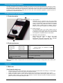
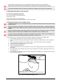
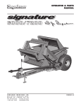
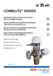
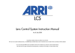
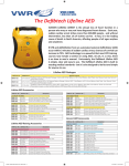
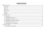
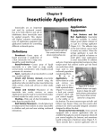
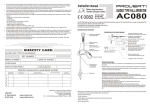
CONTROL MODULE FOR
RESUSCITATOR
GB
INSTRUCTION FOR USE
Document No:
Date of last revision:
Revision No:
Control module for resuscitator IFU, rev I
Page 1/9
1034753
20/04/2011
I
20/04/2011
1. Foreword
GCE Control modules for resuscitator are medical devices classified as class IIb according to the Medical Device
Directive 93/42/EEC.
Their Compliance with essential requirements of 93/42/EEC Medical Device Directive is based upon BS6850:2002
standard.
2. Intended use
The GCE Control module for resuscitator is standard used in the resuscitation set which may also contain oxygen
regulator, connection hoses, demand valve and mask. The set is used for resuscitation in emergency or ambulance
field.
The GCE Control module for resuscitator is an automatic gas powered time cycled system, with patient trigger and
manual override. The unit provides medical oxygen for artificial respiratory ventilation and breathing-on-demand.
The system permits conscious patients to establish their own respiratory pattern.
The apparatus is useable for a Child/ Adult resuscitation, for the normal range of body masses from 20 to 60kg
respectively. The CPR setting, however, may be used for heavier body masses, where appropriate.
The control module monitors patient breathing and automatically shuts-off artificial ventilation when spontaneous
ventilation occurs, while continuing to provide oxygen therapy. The system also covers the reverse situation, where,
should the respiratory rate drop below the pre-set level, the unit automatically starts artificial ventilation.
Once the operator has established an effective seal between the patient's face and mask, the control module is
ideally suited for resuscitation in a toxic environment, because the system is totally sealed from the external
environment.
•
Storage
Transport
Operations
3. Operational, transport and storage safety requirements
Keep the product and its associated equipments away from
- heat sources (fire, cigarettes, …),
- flammable materials,
- oil or grease,
- water,
- dust.
•
The product and its associated equipments must be prevented from falling over.
•
Always maintain oxygen cleanliness standards.
•
Use only the product and its associated equipments in well ventilated area.
Before initial use the product should be kept in its original packaging. GCE recommends use of the original packaging
(including internal sealing bag and caps) if the product is withdraw from operation (for transport, storage).
Statutory laws, rules and regulations for medical gases, accident prevention and environmental protection must be
observed.
Operation conditions
Storage and transport conditions
-10/+40 °C
•
-20/+60 °C
If the cylinder is a part of resuscitator set a maximum allowed storaged temperature is 40°C
Control module for resuscitator IFU, rev I
Page 2/9
20/04/2011
4. Personnel instructions and training
According to Medical Devices Directive 93/42/EEC the producer must ensure that all personnel handling the product
are provided with the operating instructions & performance data. The control module for resuscitator should be used
by personnel with medical education (medical man, paramedical worker, nurse) who have received adequate training
in Cardio Pulmonary Resuscitation (CPR) and the correct use of the resuscitator apparatus. Trainees need to be
supervised by an experienced person.
5. Product description and performance
5.1 Product description
B
A - Inlet connection
Connection by low pressure hose with gas specific
connector following regional or national standards to the
source of low pressure oxygen (the medical O2 regulator
ordinary). Before using make sure that the connection
between control module and low pressure source is
posible, flow through is available and no leakage appear.
B - Outlet connection
C
It is the patient side of the control module used for
connection the demand valve with mask. The connection
is realyzed by hose nipples. Before use make sure that
hose nipples are compatible with the used hosess.
C - Hanwheel of the mode selector
Mode selector which allows the seting of the control
module
function:
CPR
–
Cardio
Pulmonary
Resuscitation, Large adult, small adult, child - automatic
ventilation mode following casualty body mass.
A
5.2 Product performance
SETTING (BODY WEIGHT):
Large Adult
(60kg nominal)
Small Adult
(40kg nominal)
Child
(20kg nominal)
CPR SETTING:
TIDAL VOLUMES (15ml/kg)
900ml*
* Nominal setting, as measured on GCE
600ml*
Resuscitation set
300ml*
0 to 120L/min maximum (100L/min typical)
FREQUENCY RANGE:
18 to 22 Cycles/min
INHALATION / EXHALATION RATIO:
1 : 2 Nominal
PAUSE TIME RELEVANT TO REVERT TO
AUTOMATIC VENTILATION:
4 to 6 seconds approximately
WEIGHT:
1.2kg (2.6lbs)
Note: Specification values are approximate. The manufacturer reserves the right to change these values without prior
notification.
6. Operations
6.1 Before use
Visual Inspection before use
•
•
•
Check if there is visible external damage to the product (including product labels and marking). If it shows signs
of external damages, remove it from service and identify its status.
Visually check if the product is contaminated; if needed, use the cleaning procedure detailed in this section
Check if the product service is due or that the total life time of the product and the gas cylinder has not been
exceeded, (refer to GCE or owner’s date coding system). If service or life time has been exceeded, remove the
product from service & suitably identify its status.
Control module for resuscitator IFU, rev I
Page 3/9
20/04/2011
•
Ensure that the product inlet connector is compatible with the low pressure source of medical gas
•
Remove caps from inlet and/or flow outlet. Keep caps in a safe place for reuse during transport or storage.
•
The product is dedicated only for use with the gas specified on its labelling. Never try to use for another gas.
6.2 Operational instructions, and accessories
6.2.1 List of recognised accessories
To be connected to the control module outlet:
Demand valve, mask
To be connected to the control module inlet:
Flexible hoses, high pressure medical regulator, shut-off valve, cylinder
6.2.2 Using resuscitator unit in respiratory arrest
•
Continually check the hose for cranking and necking. The patient must be under continual control during
using the device.
•
During resuscitation, frequently monitor the casualty's pulse, pallor and pupils. Frequently monitor the
cylinder contents gauge. When the pressure drops to the mid- position in the red sector, replace the
cylinder.
•
When resuscitating children under 20kg, gently press the trigger while watching the chest rise and fall.
DO NOT prolong or sustain trigger operation as over-inflation may occur in extreme cases.
•
In normal, non-toxic, breathable air, Expired Air Resuscitation should be commenced immediately if no
breathing is detected and continued until the resuscitator is ready for use.
On arrival at the scene of the incident, assess the situation for danger to yourself and the casualty, then:
1. Ensure that the casualty's mouth is clear of debris, vomit, and loose dentures.
2. Open and maintain the airway by extending the head and neck using a rolled blanket or coat to support the
neck.
3. Check the casualty's breathing, pulse, pallor and pupils. Listen, feel and look for signs of respiration.
4. Loosen restrictive clothing at the neck, chest and waist.
5. Open the case using snap fasteners.
6. Ensure the cylinder is turned ON.
7. Take the Demand Valve from the resuscitator box and connect the appropriate face mask. Place adjacent to
the casualty.
8. Check the airway is clear and place face mask over the casualty's face ensuring a tight seal round the nose
and mouth (Fig. 1).
9. Give 2 inflations to saturate the lungs with oxygen using the manual trigger (Fig. 1) watching the rise and fall
of the chest at the same time.
Fig. 1: Position of Mask with Trigger in use
Control module for resuscitator IFU, rev I
Page 4/9
20/04/2011
•
Excess pressure caused by a blocked airway (possibly due to: patient position or vomit) will set off the
relief valve and audible alarm on the demand valve.
10. Re-check breathing, pulse, pallor and pupils. If no pulse is found, follow the procedure overleaf entitled:
Using Resuscitator Unit in Cardiac Arrest
11. If a pulse is present, but no breathing is detected, select the appropriate mode on the ventilation unit (i.e.
large adult, small adult or child). The unit will now ventilate automatically. When used in automatic mode,
ensure that the airway is maintained and monitor casualty's pulse, pallor and pupils frequently.
12. When the casualty commences breathing, the unit switches to demand flow automatically, allowing the
casualty to breathe unassisted through the unit. Should the casualty's respiratory rate drop below the preset levels, the unit reverts to automatic mode.
13. Having successfully ventilated the casualty and established a good respiratory rate, check the casualty for
any further injuries, "medi alerts". Turn the casualty into the recovery position.
14. Treat the casualty for shock. Reassure the casualty and DO NOT LEAVE until the medical services arrive.
15. Use the head harness to maintain mask to face seal during transportation of the casualty.
16. If breathing and/or circulation cease, recommence resuscitation.
6.2.3 Using resuscitator unit in cardiac arrest
•
Throughout resuscitation, frequently monitor the casualty's pulse, pallor and pupils. Frequently monitor
the cylinder contents gauge. When the pressure drops to the mid- position in the red sector, replace the
cylinder.
•
When resuscitating children under 20kg, gently press the trigger while watching the chest rise and fall.
DO NOT prolong or sustain trigger operation as over-inflation may occur in extreme cases.
•
In normal, non-toxic, breathable air, Expired Air Resuscitation should be commenced immediately if no
breathing is detected and continued until the resuscitator is ready for use.
On arrival at the scene of the incident, assess the situation for danger to yourself and the casualty, then:
1. Ensure that the casualty's mouth is clear of debris, vomit, and loose dentures.
2. Open and maintain the airway by extending the head and neck using a rolled blanket or coat to support the
neck.
3. Loosen restrictive clothing at the neck, chest and waist.
4. Check breathing, pulse, pallor and pupils. Listen, feel and check for signs of respiration.
5. Open the case using snap fasteners.
6. Ensure the cylinder is turned ON.
7. Take the Demand Valve from the resuscitator box and connect the appropriate face mask. Place adjacent to
the casualty.
8. Select CPR mode on the control module.
9. Check the airway and place the face mask over the casualty's face ensuring a tight seal round the nose and
mouth (Fig. 2).
Fig. 2: Position of Mask with Trigger in use
Control module for resuscitator IFU, rev I
Page 5/9
20/04/2011
10. Use the manual trigger to give 2 inflations that will saturate the lungs with oxygen (Fig. 2), whilst watching
the rise and fall of the chest.
11. Check the carotid pulse in the neck (Fig. 3).
•
The pulse at the wrist is unreliable. If a pulse is present but no breathing is detected, follow the
procedure in Section 6.2.2 entitled:
Fig. 3: Position of pulse
Using Resuscitator Unit in Respiratory Arrest
12. If a pulse is not detected: place the heel of one hand two finger widths up from Solar Plexus at the junction
of the rib margins at the bottom of the breast bone (Fig. 4), then place the heel of the other on top (Fig. 5).
13. Keep fingers off the chest, lock your arms at the elbows and apply firm controlled vertical pressure to
compress the Sternum to a maximum of 40mm to 50mm (1.5 to 2 inches).
Fig. 4: Hand Position over Heart
One man operation
15 Compresions – 2 Ventilations – Check pulse
1. Complete 15 compressions at the rate of 80 per minute. The compressions should be regular and smooth,
not jerky and jabbing.
2. Tilt the casualty's head back and check airway is clear.
Control module for resuscitator IFU, rev I
Page 6/9
20/04/2011
3.
4.
Fig. 5: Attitude of Hands
Use the trigger to give TWO ventilations of the lungs (Fig. 1), continue with 15 compressions and again, 2
ventilations. Continue repeating the cycle as above.
After the first minute check the pulse and thereafter check the pulse every 3 minutes with minimum
disruption to the resuscitation sequence.
Two man operation
5 Compresions – 1 Ventilations – Check pulse
1. Complete 5 compressions at the rate of 80 per minute. The compressions should be regular and smooth,
not jerky and jabbing.
2. Tilt the casualty's head back and check that the airway is clear.
3. Use the trigger to give ONE ventilation of the lungs (Fig. 1), continue with 5 compressions and again, 1
ventilation. Continue repeating the cycle as above.
4. After the first minute check the pulse and thereafter check the pulse every 3 minutes with minimum
disruption to the resuscitation sequence.
Checking for Response
When resuscitation is successful the carotid pulse will return. Look at the casualty's face and lips - their colour will
improve as oxygenated blood begins to circulate. If the casualty is not breathing their normal colour will turn to
blue, cyanosis.
Maintain this cycle until cardiac output is achieved or ordered to stop by a medically qualified person. When stable:
1.
2.
3.
4.
Place the casualty in the recovery position and treat for shock, continually reassuring the casualty
throughout.
DO NOT LEAVE the casualty until the arrival of the medical services.
Use the head harness to maintain the mask to face seal during transportation of the casualty.
If breathing and/or breathing and circulation cease, recommence resuscitation.
6.2.4 List of accessories
To be connected to the control module outlet:
Demand valve, mask
To be connected to the control module inlet:
Flexible hoses, high pressure medical regulator, shut-off valve, cylinder
•
Before using of any accessories make sure that it is following valid standard and is compatible with the control
module and performance of the control module or the accessories wasn´t negativaly affected.
6.3 After use and monthly test
1.
2.
3.
4.
Ensure that the pin index yoke seal is clean, in good condition and fully tightened.
Open the cylinder valve, two turns anti-clockwise, with the key provided.
Select CPR setting on the unit.
Check that the contents gauge reads more than three-quarters full. If it does not, refill or replace the
cylinder.
5. Close the cylinder valve, watch the gauge and check that the reading has not changed after 5 seconds. If
the equipment fails this leak test, return for servicing.
6. Select Large Adult setting on the unit. After a few moments the unit will operate at 18 - 22 cycles/min.
7. Block the patient port and flick the trigger. Check that the airway blockage alarm sounds.
8. Flick the trigger several times and ensure that there is a free flow of gas. Listen carefully for leaks. Release
the trigger and note the time delay before ventilation resumes (approximately 4 to 6 seconds).
9. Close the cylinder valve and operate trigger to discharge pressurised gas.
10. Carefully pack unit and accessories, ready for use.
11. Record details of test in accordance with Section 8.3
•
Disconnect the gas supply and depressurise the system before cleaning and dismantling.
•
DO NOT dismantle the apparatus beyond the instructions in this manual unless you are fully trained and
in possession of the appropriate instructions.
Control module for resuscitator IFU, rev I
Page 7/9
20/04/2011
7. Cleaning
Remove general contamination with a soft cloth damped in oil free oxygen compatible soapy water & rinse with clean
water.
Disinfection can be carried out with an alcohol-based solution (spray or wipes).
If other cleaning solutions are used, check that they are not abrasive and that they are compatible the product
materials (including labels) and gas.
•
Do not use cleaning solutions containing ammonia!
•
Do not immerse in water or any liquid.
•
Do not expose to high temperature (such as autoclave).
8. Maintenance
8.1 Service and Product Life time
Service
GCE recommend that a product Periodic inspection is undertaken every month (following Section 6.3). It should be
done by skilled technician.
GCE recommend that after 5 years of operation an Overall maintenance function is undertaken. This maintenance
consists of preventive maintenance operations, replacement of critical components and re-testing of the product.
Overall maintenance shall be carried out by GCE authorised person only.
It should not be assumed that the Periodic Inspection and Overall Maintenance period recommended by GCE cover
every safety procedure or practice required by local regulations or statutory requirements, or that abnormal or
unusual circumstances may not warrant or suggest further requirements or additional procedures.
Life time
Maximum life time of the product is 20 years.
At the end of the product’s life time, the product must be withdrawn from service. The owner shall put in place a
relevant procedure to ensure the product cannot be used again.
8.2 Repairs
Repairs
The repairs shall be carried out by a GCE authorised person only.
Any product sent back to a GCE authorised person for maintenance shall be properly packaged. The purpose of the
maintenance has to be clearly specified (repair, overall maintenance). For product to be repaired a short description
of fault and any reference to a claim number might be helpful.
•
All labels on the equipment must be kept in good, legible condition by the owner and the user during the entire
product life time.
•
All seals and o-rings must be kept in dry, dark and clean environment by the owner and the user during the entire
product life time.
•
Use only original GCE components!
8.3 Maintenance report
The control module for resuscitator must be maintained and examined at least once a month. A report of each
examination must be signed by the person conducting the examination and the report kept available for inspection.
Information recorded usually includes:
1. The name and address of the employer responsible for the apparatus.
Control module for resuscitator IFU, rev I
Page 8/9
20/04/2011
2.
3.
4.
5.
6.
Particulars of the type of apparatus and of the distinguishing number or mark, together with a description
sufficient to identify the apparatus and the name of the maker.
The name of the person conducting the tests together with their signature or authentication mark.
The date of the examination.
The condition of the apparatus and the particulars of any defect found at the examination.
The pressure of oxygen in the supply cylinder.
A Breathing Apparatus Log Book, (Article Number 1034745), is available from GCE for recording this information.
9. Glossary
ary
Suitable for Home care use
Upper and lower humidity limit
Suitable for Hospital care use
Keep away from oil and grease
Suitable for Emergency care use
Keep away from heat and flammable material
Keep dry
Upper and lower temperature limit
Serial number
Date of manufacture
Batch number
Manufacturer
Reference number
10. Warranty
GCE guarantees the control module for one year or in accordance with statutory warranty rights, from date of
delivery, against faulty design, material & workmanship.
GCE shall not be liable for loss of production, loss of profit or any other consequential damage or indirect loss. In the
event of any fault in the goods due to defective design, materials or workmanship, our liability is limited to
replacement of these goods, provided that written notification is given to GCE within three months of the date of
delivery or deemed delivery, or such shorter time as may be specified in the quotation. Goods returned to GCE will
not be accepted unless GCE written consent to their return has previously been obtained.
The liability of the control module is irrevocably transferred to the owner or operator to the extent that it is modified, serviced or
repaired by personnel not employed or authorised by GCE or if the apparatus is used in a manner not conforming to its
intended use.
GCE cannot be held responsible for the misuse of the equipment in case of non-application of the instructions for use.
Manufactured by
GCE s.r.o.
Zizkova 381
583 81 Chotebor
Czech Republic
Control module for resuscitator IFU, rev I
Tel : +420 569 661 111
Fax : +420 569 661 602
http://www.gce-online.com
© GCE s.r.o.
Page 9/9
20/04/2011