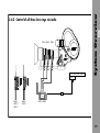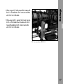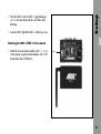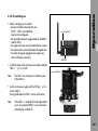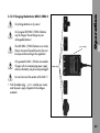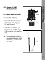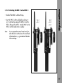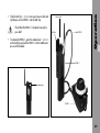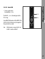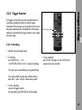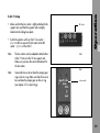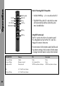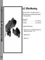
1
LCS
Lens Control System Instruction Manual
As of: July 2000
ALL
THEY MUST NOT
BE COPIED FOR REPRODUCTION (E.G. ON
ARTWORK, PICTURES AND TEXTS ARE COVERED BY OUR COPY-RIGHT.
CD-ROM DISKS OR INTERNET-SITES) OR USED IN THEIR ENTIRE FORM OR IN EXCERPTS WITHOUT OUR PREVIOUS
IF YOU ARE DOWNLOADING PDF-FILES FROM OUR INTERNET HOME-PAGE FOR YOUR PERSONAL USE, MAKE SURE TO CHECK FOR UPDATED VERSIONS.
WE CANNOT TAKE ANY LIABILITY WHATSOEVER
FOR DOWNLOADED FILES, AS TECHNICAL DATA ARE SUBJECT TO CHANGE WITHOUT NOTICE.
WRITTEN AGREEMENT.
WMU-1
WZU-1
WFU-1
CLM-1
CLM-2
RF-LED
belt attachement knob
LENS-LED
slider
LENS key
locking screw
CAL-LED
CAL key
slider
zoom-
drive direction switch
speed
RDY-LED
BAT-LED
LENS-LED
selector switch
switch
READY-LED
KNOB-LED
zoom lever
LENS-LED
RUN-LED
LENS key
RUN key
KNOB key
LENS key
WBU-1/WBU-2
RELEASE key
belt attachement
knob
radio channel
ON key
POWER key
socket for
READY-LED
Focus-Iris-unit
POWER key (ON)
BAT-LED
BAT-LED
READY-LED
CAL key
CAL key
socket for
CAL-LED
CAL-LED
motor unit
SET F-STOP-LED
SET-LED
F-STOP key
NON LINEAR-LED
SET key
RS-232
zoom lever
socket
RUN-LED
OPEN key
ICU-1
ZAP key
radio channel
RS-socket
zoom socket
LCS-socket
focus socket
CCU-socket
iris socket
CLOSE key
RUN key
speed wheel
drive direction switch
KNOB key
LENS key
MEM key
KNOB-LED
READY-LED
memory area display
Focus/Iris switch
CAL-LED
REC key
LENS-LED
REC-LED
socket for
PLAY key
Trigger contact
PLAY-LED
ZMU-1
FIU-1
URM-1
READY-LED
ON switch
UMC-1
1.
Contents ....................................................... 3
2.
Safety Specifications ................................. 7
ICU-1 Iris Control Unit ............................ 15
Power Supply ......................................... 15
Cables ................................................... 15
Contents
1. Contents
Diagram System Overview ........................ 16
3.
The System .................................................. 9
3.1
Easy Electronic Lens Control ......................... 9
3.2
System Components .................................... 9
CLM-1 Controlled Lens Motor .................. 11
CLM-2 Controlled Lens Motor .................. 11
UMC-1 Universal Motor Controller .......... 11
URM-1 Universal Radio Module .............. 11
WMU-1 Wireless Main Unit .................... 13
WBU-1/WBU-2 Wireless Battery Unit ..... 13
WAC-1 Wireless Accumulator Charger .... 13
WZU-1 Wireless Zoom Unit .................... 13
WFU-1 Wireless Focus Unit .................... 13
WEU-1 Wireless Extension Unit ............... 13
ZMU-1 Zoom Main Unit ......................... 15
FIU-1 Focus Iris Unit ............................... 15
3.3
3.3.1
3.3.2
System Overview ...................................... 17
Motor Units ............................................ 17
Manual Control Units .............................. 17
3.4
3.4.1
3.4.2
3.4.3
3.4.4
Typical Examples of Use ............................. 18
Radio remote control of focus .................. 18
Control of all three lens rings via radio .... 19
Control of the zoom ring via cable ........... 20
Control of the zoom ring via cable
and focus via radio ................................ 21
Control of all three lens rings via cable .... 22
3.4.5
3
Contents
4.
4.1
4.1.1
4.1.2
4.2
Setup .......................................................... 23
Installing and Connecting the Lens Motors .. 23
Selection of lens motors
and their power supply ........................... 23
Attaching and connecting
the motors ............................................. 26
Attaching and Connecting
the Manual Control Units ........................... 33
5.
5.1
5.1.1
5.1.2
5.1.3
5.1.4
5.1.5
5.1.6
5.2
5.2.1
5.2.2
5.2.3
5.2.4
5.2.5
5.2.6
4
Operation .................................................. 35
Radio Remote Control ................................ 35
Manual control units
for radio remote control .......................... 35
Operating the WMU-1 (Wireless Main Unit) .. 36
Operating the WZU-1 (Wireless Zoom Unit) .. 47
Operating the WFU-1 (Wireless Focus Unit) ... 50
Operating several units ........................... 56
Radio Unit accessories ............................ 57
Remote Control via Cable ........................... 61
Manual control units
for remote control via cable .................... 61
Operating the ZMU-1 (Zoom Main Unit) .. 61
Operating the FIU-1 (Focus Iris Unit) ....... 68
Memory Module .................................... 72
Trigger Function ..................................... 75
ICU-1 (Iris Control Unit) .......................... 77
Mechanical Accessories .......................... 97
7.
7.1
7.2
7.3
7.4
7.5
7.6
7.7
7.8
7.9
Trouble-Shootng ..................................... 105
Power Supply ....................................... 105
UMC-1 Universal Motor Controller LEDs ... 106
CLM-1 Motor Unit LEDs ........................ 107
WMU-1 Wireless Main Unit LEDs .......... 108
WZU-1 Wireless Zoom Unit LEDs .......... 110
WFU-1 Wireless Focus Unit LEDs ........... 111
ZMU-1 Zoom Main Unit LEDs ................ 112
FIU-1 Focus/Iris Unit LEDs ..................... 114
ICU-1 Iris Control Unit LEDs .................. 115
6.1
Mounting on Ø 15mm Support Rods .......... 97
Replace the offset clamp unit
on the CLM-1 ......................................... 97
Mounting diminishing brackets
on the motor unit CLM-2 ......................... 98
Mounting the diminishing backets
on the console ........................................ 98
6.2
Offset Mountig ........................................ 100
6.3
Panhandle Holer ..................................... 101
8.
Index ........................................................ 117
6.4
Motor Holder or ARRIFLEX 35 III ............... 101
Mounting the motor holder .................... 101
9.
Technical Data ......................................... 125
Description of System Components ........ 125
Power Supply ....................................... 125
Torque of Motor Unit ............................ 126
Weight ................................................ 126
Operating Noise Level .......................... 126
Temperature Range .............................. 126
Memory Module .................................. 126
Iris Control Unit ICU-1 .......................... 127
10.
ARRI Service ............................................ 128
6.5
Movable Irisrive Gear .............................. 102
Mounting the Movable Iris Drive Gear ... 102
6.6
Iris Drive Gar .......................................... 103
6.7
Iris Gear Ris ............................................ 103
Contents
6.
5
6
As the end-stops of the iris ring on the
ARRIMACROS change when the lens is focussed,
the ARRIMACROS may not be used with the
LCS or the WRC-1 system.
• The Lens Control System – LCS – has been thoroughly
tested for quality of workmanship and operating
functions before leaving the factory.
• To ensure optimal performance, it is essential that you
acquaint yourself with this instruction manual.
Meaning of the symbols in this user manual
• Set-up and operation of the LCS unit should only be
carried out by persons who are familiar with the
equipment!
• In wet weather the usual precautions for use of electrical
equipment must be taken!
➪ photo indicates objects which are shown in the
illustration.
• Warning indications:
Caution! - means injury possible
Attention! - means damage to equipment possible
• Do not use solvents to clean the LCS!
• Do not loosen any screws which are painted over!
Note:
Safety Specifications
2. Safety Specifications
Further information or indications of possible
incorrect operation.
• Use only original ARRI spare parts and accessories!
Product Identification
• Repairs must only be carried out by authorised
professionals!
When ordering parts or accessories, or if any questions
should arise, please advise your type of product and
serial number.
7
8
3.1 Easy Electronic Lens
Control
The ARRI Lens Control System – LCS – is an easy-to-use remote control system for camera lenses. A compact, modular
system that can be expanded from simple zoom control to
a complete remote-control system for zoom, focus and iris.
It can be operated via radio or remotely controlled via a
cable. The system covers all control possibilities for
standard lenses for ARRIFLEX cameras and can also be
used on cameras from other manufacturers.
3.2 System Components
All operations of the lens control system can be performed
with the flexible individual units. In general, all units are
abbreviated using a code with three letters, a hyphen and
a number (e.g. CLM-1). All cables are abbreviated using
a code with two letters, a hyphen, a letter and a number
(e.g. UC-C1). The Lens Control System consists of the
following units:
System Overview
3. The System
The user can adapt the LCS with its varied functions to his
own needs, for example adjustment range and speed as
well as transmission ratio – at the touch of a button.
With the optional memory module programs and settings
can be stored and repeated.
9
System Overview
UMC-1
URM-1
CLM-1
10
CLM-2
UMC-1 Universal Motor Controller
The main features of the motor units CLM-1 ➪ photo are
their high torque; they are particularly suited to work with
stiff lenses or in cold weather. The vertical mounting allows
the motor unit to be attached even when the available space
for the set-up is restricted. The motor units can be installed
on and removed from the fully equipped camera. The matte
box does not need to be removed.
The universal motor controller UMC-1 ➪ photo is used to
control the CLM-2 motors on the camera. Up to three CLM-2
motors (zoom, focus, iris) can be controlled. Mixed
operation with CLM-1 and CLM-2 motors is also possible.
CLM-2 Controlled Lens Motor
The small, lightweight motor units CLM-2 ➪ photo are
particularly suited to applications for which weight and size
are decisive factors, for example Steadicam shots, when
using 16mm or video cameras, or with sensitive lenses.
As with the CLM-1 motor units the vertical mounting enables
working in particularly tight conditions. The consoles to the
motors enable very flexible mounting. To use a CLM-2
motor, the universal motor controller UMC-1 is necessary.
URM-1 Universal Radio Module
The Universal Radio Module URM-1 ➪ photo is mounted
to the UMC-1 and provides the radio connection to the
WMU-1.
System Overview
CLM-1 Controlled Lens Motor
11
System Overview
WCE-1
WZU-1
WMU-1
12
WAC-1
WFU-1
WMA-1
WHA-1
WFU-1 Wireless Focus Unit
The WMU-1 ➪ photo is the central main unit for radio
remote control and provides the radio connection from the
manual control units to the URM-1. With the WMU-1
various manual control units (WZU-1, WFU-1) can be
combined to remotely control the lens and camera. Three
WMU-1 can be operated simultaneously with the system.
The wireless focus control unit WFU-1 ➪ photo can be
attached to the WMU-1 to enable radio remote control of
the lens iris and focus.
WBU-1/WBU-2 Wireless Battery Unit
The battery WBU-1/WBU-2 ➪ photo is used to power
the WMU-1.
WAC-1 Wireless Accumulator Charger
WEU-1 Wireless Extension Unit
The extension WEU-1 ➪ photo consists of three components
which enable the WMU-1 to be worn on a belt so that
only the manual control unit needs to be held:
the adapter WHA-1 (Wireless Handgrip Attachment),
➪ photo, the cable WC-E1 ➪ photo and the WMA-1
(Wireless Main Attachment) ➪ photo.
System Overview
WMU-1 Wireless Main Unit
The Battery Charger WAC-1 ➪ photo is used to charge
the WBU-1 battery.
WZU-1 Wireless Zoom Unit
The wireless zoom control unit WZU-1 ➪ photo can be
attached to the WMU-1 to enable wireless remote control
of the focal length on a zoom lens.
13
System Overview
FIU-1
ZMU-1
14
ICU-1
Power Supply
The zoom unit ZMU-1 ➪ photo is the main control unit
for all configurations remotely controlled via cable. It
enables the focal length of zoom lenses to be adjusted by
remote control.
The LCS is operated with a separate 24V or 12V battery.
The LCS can also be powered directly from the camera,
provided the rated load of the camera socket is not
exceeded.
FIU-1 Focus Iris Unit
Cables
The focus iris unit FIU-1 ➪ photo can be used for remote
focus as well as remote iris control. It is user-friendly and
can be operated on the same principles as the mechanical
follow-focus system. To use an FIU-1, a ZMU-1 is always
necessary.
A modular cable-connecting system allows easy connection
from one unit to the other, as well as to the system operating
control. The LCS recognises connected units and also
detects defective cables.
System Overview
ZMU-1 Zoom Main Unit
ICU-1 Iris Control Unit
The ICU-1 ➪ photo provides constant exposure during
speed-ramps. It constantly monitors the frame rate of the
camera. During a frame rate change, the ICU-1 will
calculate a new value for the iris to compensate for the
exposure change, and instruct the lens motor to change
the iris ring accordingly.
15
LOCK
CLM-2
RF
CAL
WMU-1
LENS
ZOOM SPEED
System Overview
Diagram System Overview
+ WZU-1
UC-C1
+WFU-1
BAT RDY
RUN
UC-C2, UC-C4, UC-C5
UC-S1
max. 3 WMU-1
LC-M1
LENS CONTROL SYSTEM
WMU-1
L
IRIS
R
POWER
BAT
LC-D1, LC-D2, LC-D3, LC-D4
READY
CAL
L
ZOOM
IRIS
R
L
ZOOM
IRIS
R
ZOOM
FOCUS
FOCUS
FOCUS
READY
READY
READY
to camera
CLM-1
URM-1
SET F-STOP
NONLINEAR
OPEN
IRIS
CLOSE
LC-M1
UMC-1 + URM-1
ICU-1
LC-S2, LC-S3, LC-S4
LC-M1 LC-M1
LC-M2 LC-M2
LC-Z1, LC-Z2
FIU-1
FIU-1
LC-F1, LC-F2
UC-A1
ZMU-1
16
LC-S1
LC-F1, LC-F2
LC-E1
24/12V
LC-C1, LC-C2, LC-C3
The illustration on the left page provides an overview of
the entire system with the various units, their relation to
each other, and which cables are used to connect the units.
For typical examples of use please see the following pages.
3.3.2 Manual Control Units
With the various manual control units, up to 3 lens motors
can be controlled via cable or radio. The camera can be
started or stopped with the units
• ZMU-1 (Zoom Main Unit) (via cable)
• and WMU-1 (Wireless Main Unit) (via radio).
For remote control via cable the ZMU-1 is always necessary.
It is either connected to the UMC-1 or a CLM-1 motor. If
iris and/or focus are to be controlled, up to two Focus Iris
Units FIU-1 can be attached to the ZMU-1.
3.3.1 Motor Units
The LCS enables a maximum of three lens motors to be
controlled via the manual control units. The CLM-1 motors
are particularly useful for stiff lenses, they can be operated
with either a power cable LC-S1 (S2, S3, S4) or the UMC-1.
The CLM-2 motors are particularly useful for configurations
in restricted spaces or if weight is critical. The CLM-2
motors can only be operated together with the UMC-1.
Remote Control via Cable
Remote Control via Radio
To remotely control via radio at least one WMU-1 is always
necessary. A maximum of three WMU-1 can be operated
simultaneously. For the lens motors a UMC-1 with an
attached URM-1 is always necessary. On the WMU-1
units can be attached to control the lens zoom ring with
the WZU-1, or to control the focus ring and/or iris ring
with the WFU-1. All three lens rings can be remotely
controlled with one WMU-1 or with several WMU-1 units
in radio network operation.
System Overview
3.3 System Overview
17
3.4.1 Radio remote control of focus
CLM-2
RF
CAL
535, 535B, 435, 16 SR3
RS
LOCK
System Overview
3.4 Typical Examples of Use
BAT RDY
RUN
UC-C1
LENS CONTROL SYSTEM
WMU-1 + WFU-1
18
UMC-1 + URM-1
CLM-2 CLM-2 CLM-2
RF
CAL
RS
ZOOM SPEED
LENS
LOCK
LOCK
535, 535B, 435, 16 SR3
RF
CAL
System Overview
3.4.2 Control of all three lens rings via radio
BAT RDY
BAT RDY
RUN
RUN
UC-C1
LENS CONTROL SYSTEM
WMU-1
+ WZU-1
+ WFU-1
WMU-1
+ WFU-1
UMC-1+ URM-1
19
System Overview
3.4.3 Control of the zoom ring via cable
CLM-1
L
IRIS
R
ZOOM
FOCUS
READY
535, 535B, 435, 16 SR3
ZMU-1
LC-Z1, LC-Z2
LC-S3
LC-E1
20
CLM-1
L
CLM-2
IRIS
R
ZOOM
FOCUS
READY
LC-M1
535, 535B, 435, 16 SR3
LC-M1
LC-M2
LOCK
RF
CAL
System Overview
3.4.4 Control of the zoom ring via cable and focus via radio
RS
BAT RDY
RUN
UC-C1
LENS CONTROL SYSTEM
WMU-1 + WFU-1
ZMU-1
UMC-1 + URM-1
21
System Overview
3.4.5 Control of all three lens rings via cable
CLM-1 CLM-1 CLM-1
L
IRIS
R
ZMU-1
L
ZOOM
IRIS
R
L
ZOOM
IRIS
R
ZOOM
FOCUS
FOCUS
FOCUS
READY
READY
READY
LC-M1
LC-M2
535, 535B, 435, 16 SR3
LC-M1
LC-M2
LC-C1
LC-F1, LC-F2
LC-S1
LC-F1, LC-F2
22
LC-E1
24/12V
4.1 Installing and
Connecting the Lens
Motors
Before connecting or disconnecting electrical
connections, switch off
• the Zoom Main Unit ZMU-1,
• the Universal Motor Controller UMC-1
• and all Wireless Main Units WMU-1!
Use only 24V or 12V batteries!
Changing the setting is not necessary. The LCS
automatically recognises the voltage.
At 12V there is however a lower maximum speed
of the lens motors due to the lower torque.
4.1.1 Selection of lens motors
and their power supply
There are two different lens motors available:
The lens motors CLM-1 have a high torque and should be
used with stiff lenses or in adverse weather conditions.
Setup
4. Setup
The lens motors CLM-2 are lighter and smaller. Where
light weight and small size are important, they should be
used.
For various lens rings, different motor types can also be
used, for example a CLM-1 motor for the zoom ring and
a CLM-2 motor for the iris ring.
After selecting the control motors, the power supply for them
must be specified. The selection can be made according
to the diagram on the ➪ fold out page in the back of
this manual. In the squares is listed which units and cables
are necessary for the desired application.
The cables listed in the diagram should be connected to
the various units according to the following table:
As the end-stops of the iris ring on the
ARRIMACROS change when the lens is focussed,
the ARRIMACROS may not be used with the
LCS or the WRC-1 system.
23
Setup
To power from the battery
Code
Description
Connection between
UC-A1
Power cable UMC-1
Battery / UMC-1 or UC-S1
LC-S1
Power cable CLM-1
LC-A1
LC-A2
Length / m
Plug with no. pins
2
XLR 3*
Fischer3
Battery / CLM-1
4.5
XLR 3*
Fischer5
Battery cable
Battery / Power cable
0.15
XLR 4*
XLR 3*
Battery cable
Battery / Power cable
0.15
XLR 5*
XLR 3*
For remote RUN and to power from the camera
Code
Description
Connection between
UC-C1
Supply UMC-1 from 435, 535, 535B, 16SR3
Camera / UMC-1
Length / m
1
Plug with no. pins
Fischer3
LC-S2
Supply CLM-1 from 435, 35III, 35BL, 16SR2
Camera / CLM-1
0.8
Fischer11
Fischer5
LC-S3
Cable CLM-1 from 435+FEM, 535, 535B, 16SR3
Camera / CLM-1
0.8
Fischer9
Fischer5
Fischer3
For remote RUN when using a UMC-1 as well as to power from the camera or a battery
Code
Description
Connection between
UC-S1
UMC-1 Connection with UC-C2 C4, C5 cable
RUN cable and battery / UMC-1
Length / m
0.8
Plug with no. pins
Fischer7 and 3 Fischer3
to the camera and connection to the battery with UC-A1
UC-C2
RUN cable with 435, 35III, 35BL, 16SRII
Camera / UC-S1
1
Fischer11
Fischer7
UC-C4
RUN cable with 535, 535B, 435+FEM, 16SR3
Camera / UC-S1
1
Fischer9
Fischer7
UC-C5
RUN cable 535B, 435, 16SR3
Camera / UC-S1
1
Fischer3
Fischer7
For remote RUN when using an LC-S1
24
Code
Description
Connection between
LC-C1
RUN cable with 435+FEM, 535, 535B, 16SR3
Camera / LC-S1
Length / m
1
Fischer9
Plug with no. pins
Fischer6
LC-C2
RUN cable with 435, 35III, 35BL, 16SR2
Camera / LC-S1
1
Fischer11
Fischer6 and XLR 3*
Code
Description
Connection between
LC-M1
Motor cable
CLM-1 / CLM-1
Length / m
1
Plug with no. pins
Fischer5
Fischer5
LC-M2
Motor cable
CLM-1 / CLM-1
0.2
Fischer5
Fischer5
LC-Z1
Zoom cable
ZMU-1 / CLM-1
3.5
Fischer5
Fischer5
LC-Z2
Zoom cable
ZMU-1 / CLM-1
7
Fischer5
Fischer5
LC-E1
Zoom cable extension
LC-Z1 or LC-Z2 / CLM-1
75
Fischer5
Fischer5
LC-F1
Focus cable
ZMU-1 or FIU-1 / FIU-1
2
Fischer10
Fischer10
LC-F2
Focus cable
ZMU-1 or FIU-1 / FIU-1
0.2
Fischer10
Fischer10
Setup
To cable the cable manual control units
*) Assignment of pin contacts
Type
pins
XLR
3-pin
XLR
4-pin
XLR
5-pin
Assignment
1
Ground
2
+ 24V or + 12V DC
1
Ground
4
+ 24V or + 12V DC
1
Ground
3
+ 24V or + 12V DC
If the LCS is to be powered by a camera from another
manufacturer, the relevant information should be obtained
from that manufacturer.
25
Setup
4.1.2 Attaching and connecting
the motors
Attaching the motor unit CLM-1
selector switch
• Clamp the motor unit CLM-1 ➪ photo on the lens
support rods. Make sure the motor unit’s drive gear
engages the lens’ gear.
Ensure as little play as possible!
READY LED
• Lenses with laterally moving gears:
with the motor unit engaged, turn the lens ring manually
through its entire range to ensure perfect movement.
Do not press the motor too hard in order to prevent
tilting of the shift unit.
drive direction switch
• Turn the selector switch ➪ photo on the motor unit to
poition corresponding to the lens ring
• Select the drive direction with the switch (L/R) ➪ photo
on the motor unit CLM-1.
Note:
CLM-1 motor
26
The operating direction of the motor unit can be
altered at any time (except during the calibration
process).
Setup
• When using an LC-S1 cable, connect the first motor with
the LC-S1 and additional CLM-1 motors to each other
with LC-M1 or LC-M2 cables.
• When using a UMC-1, connect the first motor with an
LC-M1 or LC-M2 cable to the LCS-socket on the UMC-1.
Connect the additional CLM-1 motors to each other
with LC-M1 or LC-M2 cables.
CLM-1 motor mounted at an ARRIFLEX 35 III
27
Setup
Mounting the CLM-2 with /without a console
locking lever
tube
Order number of the console: K2.52035.0
• Flip up the locking lever ➪ photo and screw back the
ballcatch ➪ photo with a screwdriver until it disappears
completely in the bracket.
receptacle
ballcatch
• Push the tube ➪ photo flush into the console receptacle,
taking care that the slit in the tube points towards the
ballcatch.
• Screw the ballcatch out of the bracket until the tube
can no longer be pushed out of the bracket.
• Turn the locking lever until a slight resistance can be
felt, then press the lever downwards.
• Fasten the motor unit CLM-2 to the console tube.
28
Setup
• Fasten the console to the support rods so that the motor
unit’s drive gear engages with the gear of the lens ring.
Ensure as little play as possible!
• Lenses with laterally moving gears:
with the motor unit engaged, turn the lens ring manually
through its entire range to ensure perfect movement.
Do not press the motor too hard in order to prevent
tilting of the shift unit.
The motor unit CLM-2 can also be mounted directly onto
the support rods without the console.
assembly with console
29
Setup
• Attach the plug of the motor unit CLM-2 to the socket
➪ photo of the universal motor controller UMC-1
which corresponds to the lens ring.
antenna
zoom
focus
• Select the drive direction with the switch (L/R) ➪ photo
on the universal motor controller UMC-1.
iris
UMC-1
Note:
The operational direction of the motor can be
altered at any time (except during the calibration
process).
URM-1
drive direction switches
Attaching the URM-1 (Universal Radio Module)
to the UMC-1 (Universal Motor Controller)
screw
For radio operation the UMC-1 ➪ photo must be equipped
with a URM-1 ➪ photo.
• Remove all cables from the UMC-1.
• Screw the antenna ➪ photo onto the threaded bushing
on the URM-1.
screw
30
• Unscrew both screws ➪ photo from the cover and
remove the cover.
Setup
• Place the URM-1 onto the UMC-1, align both plugs ➪
photo with each other and do not tilt them while
attaching.
• Screw the URM-1 tight to the UMC-1 with the two screws.
Attaching the UMC-1/URM-1 to the camera
• Attach the universal motor controller UMC-1 ➪ photo
to the camera using the dovetail adapter with a 3/8"
thread (Ident-No. K2.52080.0).
plug
31
32
Setup
After cabling up the motors and their power supplies, it is
necessary to define which manual control units will be used
to control the motors. The selection can be made using the
diagram on ➪ the fold-out page in the back of this
manual. In the squares is listed which units and cables are
necessary for the desired application.
Setup
4.2 Attaching and Connecting the Manual Control Units
Connect the cables listed in the diagram with the different
units according to the following table:
To cable the cable manual control units
Code
Description
Connection between
LC-Z1
Zoom cable
ZMU-1 / CLM-1
LC-F1
Focus cable
LC-F2
Focus cable
Note:
Length / m
Plug with no. pins
3.5
Fischer5
Fischer5
ZMU-1 or FIU-1 / FIU-1
2
Fischer10
Fischer10
ZMU-1 or FIU-1 / FIU-1
0.2
Fischer10
Fischer10
The focus iris unit FIU-1 cannot be used together
with a WFU-1 in radio operation.
Note:
The zoom cable LC-Z1 can be extended by 75 m
with the cable drum LC-E1.
33
Operation
WMU-1
WZU-1
34
WFU-1
5.1 Radio Remote Control
5.1.1 Manual control units
for radio remote control
In general for remote control via radio always at least one
WMU-1 (Wireless Main Unit) ➪ photo is necessary as a
radio main unit. As a maximum, three WMU-1 can be
operated simultaneously. A UMC-1 (Universal Motor
Controller) with a URM-1 (Universal Radio Module) must
be used to control the motors on the camera.
Through the flexible design of the system, optimal manual
operations for radio remote control can be created as
desired. It is possible to remotely control the various setting
rings on a lens as desired with a single or up to three WMU-1
radio remote controllers in radio network operation.
General features
Two units can be attached to the WMU-1 to remotely
control the lens:
Operation
5. Operation
• the WZU-1 (Wireless Zoom Unit) ➪ photo
to remotely control the zoom ring.
• the WFU-1 (Wireless Focus Unit) ➪ photo
to remotely control the focus and/or iris ring.
Both units can be attached together to the WMU-1;
the WZU-1 is then attached first and then the WFU-1
onto the WZU-1.
35
Operation
5.1.2 Operating the WMU-1
(Wireless Main Unit)
5.1.2.1 Selecting the radio channel
On the WMU-1 and the UMC-1, various radio channels
can be set. So that one or more WMU-1 units (maximum:
three) and one UMC-1 will work with each other, these
must all be set to the same radio channel.
Switch setting
Countries
0
USA, Canada, Mexico, New Zealand, Europe
If several lenses are to be remotely controlled independently
of each other, each UMC-1 used must be set to a different
channel. The following radio channels can not be used
simultaneously:
• radio channel 0 and 5
• radio channel 1 and 6
• radio channel 3 and 7.
2
Europe except Spain
3
USA, Canada, Mexico, New Zealand, France
4
Japan
5
Australia
6
Australia
except France and Spain
1
USA, Canada, Mexico, New Zealand, Europe
except France and Spain
It is not possible to control two UMC-1 units with one
manual unit.
Due to local telecommunications regulations,
only certain channels are allowed in some
countries. Only the channels listed in the
following table may be set!
36
7
Spain
8,9
see switch setting 0
In all countries not listed in this table, radio channels from
0-7 may be programmed if there are no local telecommunication restrictions for the 2.4 GHz band.
selection of radio channel
• Set the desired channel with the rotary selection knob
➪ photo on the URM-1.
• Using the selection knob on the WMU-1 (Wireless
Main Unit/s) , set the same channel as on the URM-1.
Operation
antenna
threaded bushing
Note:
As an alternative to the wireless control a cable
WC-A1 (15m, other lengths upon request)
(K2.52081.0) can be attached to the antenna
sockets instead of the two antennas (sender and
receiver).
selection of
radio
channel
37
Operation
5.1.2.2 Quality of the radio connection
The LED RF ➪ photo shows whether the quality of the
radio transmission is sufficient. As long as the LED RF is
green, the radio connection is perfect. If the LED is illuminated
briefly red, this means that a data packet has been lost.
The packet will automatically be re-transmitted and the
lens adjustment is still correct.
RF-LED
If the LED lights up red several times briefly, or continuously,
it must be assumed that lens adjustment is no longer being
performed correctly. If the LED flashes red, the radio
connection has been interrupted for longer than a second.
If there is no radio connection for over 40 seconds, the
WMU-1 switches off.
READY-LED
38
The radio connection is best when there is visual contact
between the antennas of the URM-1 and the WMU-1 and
when the distance between URM-1 and WMU-1 is as small
as possible. The maximum range inside depends on the
particular building and is typically approx. 30m.
Outdoors the range is approx. 100m.
• Before switching on, ensure that
- the desired radio manual control units
(WFU-1, WZU-1) are attached
and correctly configured,
- the same radio channel is programmed on the WMU-1
and the URM-1,
- the support rods are securely fastened to the camera
- the motor units are securely fastened to the support rods
- the motor drive gear engages the lens gear ring
with as little play as possible.
main switch UMC-1
Operation
5.1.2.3 Switching on
READY-LED
• Switch the main switch on the universal motor controller
UMC-1 ➪ photo to ON.
main switch WMU-1
Note:
The UMC-1 must always be switched on prior
to the WMU-1.
• Switch on the power supply with the ON key ➪ photo
on the WMU-1.
During calibration no WMU-1 can be switched on.
Note:
If the UMC-1 is switched off while radio contact
exists, all connected WMU-1 units will also be
automatically switched off.
39
Operation
The READY LEDs on the WMU-1 ➪ photo and the motor
unit CLM-1 or the universal motor controller UMC-1 will
briefly illuminate red. Then the Ready LED on the WMU-1
will show the status of the LCS:
green
LCS is ready for operation
red
operating error on one unit (e.g. incorrect key pressed,
WMU-1 switched on before UMC-1)
flashing red
the selector switch on the motor unit is incorrectly set
or connected to the incorrect socket on the UMC-1
CAL-key
BAT-LED
READY-LED
Note:
The LEDs on the CLM-1 or UMC-1 flash green
when the lens reaches the end of the set operating
range.
• Calibrate the motor end stops by pressing the CAL-key
➪ photo on the WMU-1. During calibration no extra
WMU-1 can be switched on.
Note:
All WMU-1 or ZMU-1 units must calibrate all
lens rings connected to the respective unit.
• Select the desired direction with the drive direction
switch on the CLM-1 motor unit ➪ photo or on the
switches beside the sockets of the UMC-1 ➪ photo.
40
drive direction switch
CLM-1
If a lens ring was moved manually while the LCS was
switched off, the stored values for the lens end stops will
no longer be correct. So:
• switch on the LCS and recalibrate.
Operation
5.1.2.4 Resuming operation
after an extended break
5.1.2.5 Battery Control (BAT)
When the battery control LED (BAT) ➪ photo on the
WMU-1 flashes, the battery must be replaced.
The operating time of a battery is approx. 5 hours.
Do not begin any new scenes!
drive direction switch (Zoom) UMC-1
Meaning of the BAT LED signals:
illuminated red
WMU-1 will work for approx. 15 min
flashing red
WMU-1 will work for approx. 5 min
fast flashing red
WMU-1 will switch off in approx. 5 s.
41
Operation
5.1.2.6 Replacing the battery WBU-1/WBU-2
(Wireless Battery Unit)
Never place the battery contacts on a conductive
surface. Do not short-circuit the battery.
contacts
To protect the battery contacts on the WMU-1,
a battery should always be attached to the
WMU-1.
WBU-1/WBU-2
Note:
The batteries consist of 6 nickel metal hydride cells.
The rated capacity for the WBU-1 is 1.6 Ah, for
the WBU-2 is 2 Ah.
The charge time is approx. 1.5 h.
• Switch off the WMU-1 by pressing the ON key.
• Push away the locking lever ➪ photo from the
battery and pull the battery backwards to remove it.
contacts
locking lever
42
• Insert a fully charged battery with its wide black pin
facing the surface and push into the holder until the
battery clicks in audibly.
Only charge batteries in dry rooms!
Only original ARRI WBU-1/WBU-2 batteries
may be charged. Do not charge any nonrechargeable batteries!
The ARRI WBU-1/WBU-2 batteries must not be
thrown into normal household waste; they must
be disposed of according to the regulations!
Only operate the WAC-1 (Wireless Accumulator
Charger) with its accompanying power supply,
otherwise the battery may be severely damaged!
power supply
Operation
5.1.2.7 Charging the batteries WBU-1/WBU-2
adapter plug
Do not short-circuit the contacts of the WAC-1!
• Push the adapter plug ➪ photo suited to your country
onto the power supply. Alignment to the voltage is
automatic.
43
Operation
• Connect the round plug ➪ photo on the power supply
to the Charger ➪ photo.
plug
• Insert the WBU-1/WBU-2 to be charged with its wide
black pin facing the surface and push into the holder
until the battery clicks in audibly.
• Connect the power supply to the mains. The LED on
the power supply ➪ photo is illuminated red.
charger
LED
• The WBU-1/WBU-2 is fully charged when the power
supply LED flashes ➪ photo red.
• Push away the locking lever ➪ photo from the battery
and pull the fully charged battery backwards to
remove it.
locking lever
44
Operation
5.1.2.8 Calibration
The end stops of the lens rings are defined and stored during
the automatic calibration process in order to prevent driving
the lens ring up against the lens’ end stops. Previously set
values are thereby erased.
Calibration must be carried out
– during initial set-up,
– after a lens change,
– after the lens control ring has been manually
moved while the units were disconnected from
the power, e.g. after an extended break
– after the motor drive gear has been removed
from the lens control ring.
• To calibrate press the CAL key ➪ photo on the WMU-1.
While the LCS is calibrating, the CAL-LED on the
WMU-1 is illuminated yellow, the motor LEDs on the
UMC-1 are flashing red/green. Only those axes are
calibrated for which a manual control unit is available.
During calibration no extra WMU-1 can be switched on.
CAL key
BAT LED
READY LED
The CAL-LED flashes:
Lens end stops are not yet defined, or the lens
has been moved while the LCS was switched off
and then driven against the end stops. Recalibrate!
45
Operation
5.1.2.9 Camera RUN
• To start or stop the camera:
Press the RUN key ➪ photo.
The RUN-LED ➪ photo is illuminated green while the
camera is running.
In REMOTE-RUN operation with the ARRIFLEX 35 BL, 35
III and 16 SR II the camera can only be stopped with the
key with which it was started.
Note:
RUN-LED
RUN key
46
While the camera is running, the UMC-1 and
the WMU-1 cannot be switched off.
5.1.3.1 Mounting the WZU-1 on the WMU-1
release key
• Switch off the WMU-1 with the ON key.
• To detach a WFU-1 (Wireless Focus Unit) if attached,
press the release key ➪ photo, swing away the
WFU-1 and pull up to remove it.
Operation
5.1.3 Operating the WZU-1
(Wireless Zoom Unit)
WFU-1
• Insert the WZU-1 with its wide black pin ➪ photo
facing into the free space on the WMU-1, then press
the WZU-1 onto the WMU-1 until the module clicks in
audibly.
Note:
Do not separate the manual control units from
each other while switched on, as this could lead
to functional errors, e. g. unintentional alteration
of lens end stops.
WZU-1
black pin
47
Operation
5.1.3.2 Zooming
• Prior to operation, the end stops of the lens must be
calibrated (see chapter 5.1.2.8 Calibration).
LENS-LED
• Press the zoom lever ➪ photo in the desired direction.
LENS key
The focal length will be altered. The greater the force, the
faster the zoom will react.
5.1.3.3 Defining the zoom range
speed wheel
For zooming a defined range can be selected and stored.
• Drive the zoom ring to one end of the selected range.
zoom lever
• Press the LENS key ➪ photo, and hold down.
The LENS LED will flash.
• Drive the zoom ring to the other end of your selected
range, and release the LENS key
The LENS LED will now be illuminated.
When redefining the zoom range, the range can only be
smaller. If this is not desired, the zoom range must first be
erased and then redefined.
48
Operation
5.1.3.4 Erasing the zoom range
• Press the LENS key ➪ photo and hold down briefly.
The LENS-LED ➪ photo switches off.
5.1.3.5 Setting zoom speed
The sensitivity of the zoom lever is pre-selected with the
speed wheel ➪ photo. At maximum zoom speed (10), a
mains supply of 24V and full deflection of the zoom lever,
a half turn (180°) takes 1 second. At the slowest speed (1)
it takes about 2 minutes (for lenses with 130 mm diameter
gear ring). Even slower speeds can be achieved with
smaller deflections of the zoom lever.
ZAP key
5.1.3.6 ZAP-Function
• The ZAP key ➪ photo switches to maximum zoom
speed – independently of the speed wheel setting.
49
Operation
5.1.4 Operating the WFU-1
(Wireless Focus Unit)
end stops
The WFU-1 has two main operating elements:
a handwheel ➪ photo with stops ➪ photo and a slider
➪ photo. With the switch on the front side of the WFU-1
it is possible to determine whether focus or iris is to be
controlled with the handwheel. The slider then controls the
remaining lens ring.
slider
black pin
With a WFU-1, the focus and iris rings can be controlled
remotely. It is however also possible to control focus with
one WFU-1 and iris with a second WFU-1. In this case
each WFU-1 must be operated with its own WMU-1.
handwheel
If two WFU-1 units are used for focus and iris, for each
WFU-1 a separate WMU-1 is necessary. Before switching
on both WMU-1 units, the WFU-1 switches must be set to
different positions. In this case only the two handwheels
are used for control; the sliders are deactivated.
switch
As operating the handwheel and the slider is independent
from the particular lens ring (focus or iris), only operation
of the handwheel and the slider is described in the
following two chapters.
50
• Switch off the WMU-1 with the ON key.
• Insert the WFU-1 with its wide black pin facing it ➪
photo into the free space on the WMU-1 or on the
WZU-1, then push the WFU-1 onto the WMU-1 or the
WZU-1 until the module clicks in audibly.
Note:
Do not separate the manual control units from
each other while switched on as this could lead
to functional errors, e. g. unintentional alteration
of lens end stops.
WMU-1
WMU-1
+ WFU-1
+ WZU-1
+ WFU-1
Operation
5.1.4.1 Attaching the WFU-1 to the WMU-1
51
Operation
5.1.4.2 Determining whether the handwheel
should control focus or iris
end stops
• Turn the switch ➪ photo in the middle of the operating
field of the WFU-1 to the desired position.
To operate focus with the handwheel, push the switch
in the direction of the handwheel.
locking screw
5.1.4.3 Operating the handwheel on the WFU-1
handwheel
switch
LENS key
LENS key
(slider)
(handwheel)
KNOB key
52
• Prior to operation, the end stops of the used lens must
be calibrated (see chapter 5.1.2.8 Calibration).
Focus or Iris Adjustment
• Adjust the handwheel ➪ photo of the WFU-1.
The lens ring follows the handwheel adjustment very
precisely and smoothly.
When quickly turning the handwheel, focus and iris adjustment follows with the maximum speed of the lens control
motors (at 12V the maximum adjustment speed is lower).
• To fix in position, turn the locking screw ➪ photo
clockwise.
The selected operating range must cover at
least 2% of the entire lens range. Otherwise the
setting will have no effect.
Erasing the Setting Range
• Press the LENS key ➪ photo and hold down briefly
– LENS-LED switches off.
• To loosen, turn the locking screw anti-clockwise.
Defining the Adjustment Range of the Lens
For each ring on the lens controlled by the LCS, a setting
range can be defined and stored. The smaller this range,
the more precisely setting can be carried out.
With the corresponding control unit, set the range as
follows:
• Drive to the beginning of the selected range by
adjusting the handwheel.
Matching the Scale Range to the WFU-1
On the focus scale disk of the WFU-1 a scale range can be
selected by marking as desired. Previously marked focus
disks can be used, e.g. from mechanical follow-focus devices.
Operation
Fixing the Handwheel in Position
To prevent unintentional moving of the handwheel, it can
be fixed in its position.
For each WFU-1 the scale range is aligned to the stored
setting range of the lens ring as follows:
• With the mechanical end stops ➪ photo of the
handwheel, set the limits of the desired scale range
and fix them.
• Press the LENS key and hold down
– LENS-LED ➪ photo flashes.
• Turn the handwheel to the first end stop.
• Drive to the end of the selected range by adjusting the
handwheel.
• Press the KNOB key ➪ photo and hold down
– KNOB-LED flashes.
• Release the LENS key
– LENS-LED illuminates.
53
Operation
• Turn the handwheel to the second end stop and
release the KNOB key
– KNOB LED illuminates.
The set scale range must be at least 30° on the
handwheel. Otherwise the setting will have no
effect.
Erasing the Scale Range
• Press the KNOB key and hold down briefly
– KNOB-LED switches off.
Using Scales from Mechanical Follow-Focus Devices
If a focus disk is firstly to be marked on a mechanical
follow-focus device and then used on the WFU-1, it must
be set up on the follow-focus device as follows:
• Turn the handwheel on the follow-focus device
clockwise to the lens end stop.
• Move the index indicator of the follow-focus device to
the disk-positioner pin.
• Fix the index indicator in this position.
• Mark the scale.
Scales marked in this way can be used for LCS focus-iris
operation. Match the scale ranges as described above.
54
• Prior to operation, the end stops of the used lens must
be calibrated (see chapter 5.1.2.8 Calibration).
locking
screw
Focus or Iris Setting
• Shift the slider ➪ photo of the WFU-1.
The lens ring follows the sliding switch adjustment very
precisely and smoothly.
slider
Operation
5.1.4.4 Operating the slider on the WFU-1
When moving the slider very quickly, focus and iris adjustment follow at maximum speed (at 12V the maximum
speed is lower).
Fixing the Slider in Position
To prevent unintentional moving of the slider, it can be
fixed in position.
• Turn the locking screw ➪ photo clockwise to fix in
position.
• Turn the locking screw anti-clockwise to release.
55
Operation
• Drive to the end of the selected range by adjusting the
sliding switch.
switch
LENS key
LENS key
(slider)
(handwheel)
KNOB key
Defining The Lens Setting Range
For each ring of the lens controlled by the LCS, a setting
range can be defined and stored. The smaller the setting
range, the more precisely setting can be carried out.
With the corresponding control unit the range can be set
as follows:
• Drive to the beginning of the selected range by
adjusting the slider (handwheel).
• Press the LENS key and hold down
– LENS-LED ➪ photo flashes.
56
• Release the LENS key
– LENS-LED illuminates.
The selected operating range must cover at
least 2% of the entire lens range. Otherwise the
setting will have no effect.
Erasing the Setting Range
• Press the LENS key and hold down briefly
– LENS-LED switches off.
5.1.5 Operating several units
If a lens is to be remotely operated by several units
(several WMU-1), the following applies:
If two WFU-1 units are active and if their selector switches
are set to different positions, on both units only the rotary
knob is active for the selected lens ring. Both sliders on
the units are deactivated, and the sequence in which they
are switched on has no effect.
As a maximum, three WMU-1 can be operated.
WEU-1 components
In order to further reduce the weight to be held in the hand,
it is possible to fasten the WMU-1 to your belt. An extension
WEU-1 (Wireless Extension Unit) between the WMU-1
and the manual control units WFU-1 and WZU-1 is
available.
belt clip
cable WC-E1
The extension WEU-1 ➪ photo
(Ident-No. K2.52056.0) consists of:
The attachment piece for the manual controls WHA-1
➪ photo (Wireless Handgrip Attachment)
(Ident-No. K2.52070.0).
Operation
5.1.6 Radio Unit accessories
WMA-1
The attachment piece for the main unit WMA-1 ➪ photo
(Wireless Main Attachment) (Ident-No. K2.52071.0).
The extension cable WC-E1 (1m) ➪ photo
(Ident-No. K4.52336.0).
A longer cable WC-E2 (3m) is also available
(Ident-No: K2.52084.0).
WHA-1
57
Operation
Attaching the Extension WEU-1
• Switch off the WMU-1 with the ON key.
release key
• To detach a WFU-1, press the release key ➪ photo,
swing away the WFU-1 and then pull upwards to
remove it.
• Insert the WMA-1 for the WMU-1 with the wide black
pin facing into the free space on the WMU-1 (or WZU-1),
then press the WMA-1 onto the WMU-1 (or WZU-1)
until the module clicks in audibly.
• Insert the WZU-1 or the WFU-1 with its wide black pin
facing into the free space of the Wireless Handgrip
Attachment WHA-1, then press the WZU-1 or WFU-1
onto the WHA-1 until the module clicks in audibly.
• Connect the two attachment pieces WHA-1 and WMA-1
to each other with a cable WC-E1 ➪ photo or WC-E2.
58
Check that the WMU-1 is fastened securely to
your belt!
release lever
belt clip
cable WC-E1
• To release the WMU-1, press the release lever ➪ photo
on the belt clip and pull the WMU-1 with its attachment
pin out of the holder.
Operation
• Clip the belt clip ➪ photo onto your trousers belt and
clip the pin on the WMU-1 into the belt clip.
WMA-1
attachment pin
WHA-1
59
Operation
POWER key
socket for
READY-LED
focus-iris unit
POWER key
BAT-LED
CAL key
socket for
CAL-LED
motor units
READY-LED
CAL-LED
CAL key
SET F-STOP-LED
SET-LED
SET key
BAT-LED
F-STOP key
NON LINEAR-LED
RS-232 socket
zoom lever
RUN-LED
OPEN key
ZAP key
CLOSE key
ZMU-1
ICU-1
RUN key
speed wheel
KNOB key
LENS key
MEM key
KNOB-LED
READY-LED
memory area displays
focus/iris switch
CAL-LED
REC key
socket for
PLAY key
Trigger contact
PLAY-LED
60
LENS-LED
REC-LED
FIU-1
5.2.1 Manual control units
for remote control via cable
5.2.2 Operating the ZMU-1
(Zoom Main Unit)
For remote control of the lens via cable a ZMU-1 (Zoom
Main Unit) is always necessary as a main unit.
5.2.2.1 Switching on
Operation
5.2 Remote Control via Cable
• Before switching on, ensure that
- the support rods are securely fastened to the camera,
- the motors unit is securely fastened to the support rods,
- the motor drive gear engages the lens gear ring with
as little play as possible.
main switch UMC-1
READY-LED
• If a Universal Motor Controller UMC-1 is to be used,
switch its main switch ➪ photo to ON.
• Switch on the power supply with the POWER key ➪
photo on the Zoom Main Unit ZMU-1.
Note:
If the Universal Motor Controller UMC-1 is
switched off and on again, the ZMU-1must also
be reset by switching off and on.
61
Operation
The READY-LEDs on the ZMU-1 ➪ photo and the motor
unit CLM-1 or the UMC-1 briefly illuminate red, then the
READY-LED on the ZMU-1 displays the status of the LCS:
UMC-1
green
LCS is ready for operation
red
operating error on one unit
(e.g. incorrect key pressed,
ZMU-1 switched on before UMC-1)
or
LED
power cable LC-S1 defective
(see also chapter 7. Trouble-Shooting)
drive direction switch
flashing red
selector switch on the motor unit is incorrectly set
or connected to the incorrect socket of the UMC-1
motor unit is not connected
CLM-1
cable defective (see also chapter 7. Trouble-Shooting)
drive direction switch
Note:
LED
The LEDs on the CLM-1 ➪ photo or the UMC-1
➪ photo flash green if the lens is at the end of
the set operating range.
• Then press the CAL key ➪ photo on the ZMU-1to
calibrate the motor end stops.
• Select the desired drive direction of the zoom adjustment
with the drive direction switch on the CLM-1 motor ➪
photo unit or on the zoom socket on the UMC-1 ➪
photo.
62
If a lens ring was moved manually while the LCS was
switched off, the stored values for the lens end stops will
no longer be correct. So:
BAT-LED
READY-LED
• Switch on the LCS and recalibrate.
CAL-LED
CAL key
SET-LED
SET key
POWER key
Operation
5.2.2.2 Resuming operation after a break
with power down
5.2.2.3 Battery Control (BAT)
When the battery control LED (BAT) ➪ photo on the
zoom unit flashes, replace the battery.
Do not start any new scenes!
• If the battery control LED flashes, replace the battery
immediately (danger of completely discharging the
battery).
The battery control reacts to the following voltage limits:
Battery
BAT-LED
24V
illuminated
<20V
flashing
<18V
12V
Voltage
illuminated
<10V
flashing
<9V
63
Operation
5.2.2.4 Calibration
The end stops of the lens rings are defined and stored
during the automatic calibration process to prevent
driving the lens ring up against the lens’ end stops.
Previously set values are thereby erased.
CAL-LED
CAL key
SET-LED
SET key
Calibration must be carried out
– during initial set-up
– after a lens change
– after the lens control ring has been manually
moved while the units were disconnected from
the power, e.g. after an extended break
– after the motor drive gear has been removed
from the lens control ring.
• To calibrate on the ZMU-1, press the CAL key ➪ photo.
While the LCS is calibrating, the CAL-LED ➪ photo on
the ZMU-1 is illuminated yellow, the motor LEDs on the
UMC-1 ➪ photo flash red/green.
motor LEDs
64
The CAL-LED flashes:
Lens end stops not yet defined, or the lens has
been moved while the LCS was switched off and
then driven against the end stops. Recalibrate!
zoom lever
• Turn the zoom lever ➪ photo in the desired direction.
The focal distance will be altered. The greater the
deflection, the faster the zoom will react.
5.2.2.6 Defining the zoom range
For focal length adjustment, a defined range can be
selected and stored.
Operation
5.2.2.5 Zooming
• Drive the zoom control ring to the beginning of the
selected range.
5.2.2.7 Erasing the zoom range
• Press the SET key ➪ photo, and hold down.
The SET-LED ➪ photo will flash quickly.
• Press the SET key ➪ photo and hold down briefly.
The SET-LED ➪ photo switches off.
• Drive the zoom control ring to the end of the selected
range, and release the SET button. The SET-LED will
now be illuminated.
When redefining the zoom range, the range can only be
smaller. If this is not desired, the zoom range must first be
erased and then redefined.
65
Operation
zoom lever
5.2.2.8 Setting zoom speed
The sensitivity of the zoom lever is pre-selected with the
speed wheel ➪ photo. At maximum zoom speed (10), a
mains supply of 24V and full deflection of the zoom lever,
a half turn (180°) takes 1 second. At the slowest speed (1)
it takes about 2 minutes (for lenses with 130 mm diameter
gear ring). Even slower speeds can be achieved with
smaller deflections of the zoom lever.
speed wheel
5.2.2.9 ZAP-Function
The ZAP-key ➪ photo switches to maximum zoom speed
– independently of the speed wheel setting.
ZAP key
66
Camera RUN
• To start or stop the camera:
Press the RUN key ➪ photo.
RUN-LED
The RUN-LED ➪ photo is illuminated green while the
film is running.
During REMOTE-RUN operation with the ARRIFLEX 35 BL,
35 III and 16 SR II, the camera can only be stopped with
the key with which it was started.
Note:
RUN key
Operation
5.2.2.10
While the camera is running, the UMC-1 and
the ZMU-1 cannot be switched off.
67
Operation
5.2.3 Operating the FIU-1
(Focus Iris Unit)
KNOB key
LENS key
KNOB-LED
LENS-LED
focus/iris switch
READY-LED
With an FIU-1 ➪ photo either a focus ring or an iris ring
can be remotely controlled. For use of the FIU-1 a ZMU-1
is always necessary as a main unit. The first FIU-1 is connected to the ZMU-1 with a cable LC-F1 or LC-F2. If a
second FIU-1 is used, this can be connected to the first
FIU-1 with a cable LC-F1 or LC-F2.
CAL-LED
5.2.3.1 Defining the function of the FIU-1
Switch on the FIU-1 with the ZMU-1. Before switching on,
it is necessary to determine whether the FIU-1 is to control
a focus ring or an iris ring.
mechanical
end stops
fixing screw
• Using a coin, turn the switch Focus/Iris ➪ photo to
the desired position.
handwheel
Note:
FIU-1
68
If only one FIU-1 is used, the function (Focus/Iris)
can also be altered while switched on.
5.2.3.4 Defining the setting range of the lens
• Turn the handwheel ➪ photo of the FIU-1.
For each setting ring on the lens controlled by the LCS, a
setting range can be defined and stored. The smaller this
range, the more precisely setting can be carried out.
The focus ring of the lens follows the handwheel adjustment
very precisely and smoothly.
When quickly turning the handwheel, focus and iris
adjustment follow the lens control motors at maximum
speed (at 12V the maximum adjustment speed is lower).
The setting range is determined individually for each axis.
On the Focus Iris Unit the LENS key ➪ photo is used:
With the corresponding control unit, set the range as follows:
5.2.3.3 Fixing the handwheel in position
• Drive to the beginning of the selected range by
adjusting the handwheel.
To prevent unintentional moving of the handwheel, it can
be fixed in its position.
• Press the LENS key ➪ photo and hold down
– LENS-LED ➪ photo flashes.
• To fix in position, turn the locking screw ➪ photo
clockwise.
• Drive to the end of the selected range by adjusting the
handwheel.
• To loosen, turn the locking screw anti-clockwise.
• Release the LENS key
– LENS-LED illuminates.
Operation
5.2.3.2 Focus or iris setting
The selected operating range must cover at
least 2% of the entire lens range. Otherwise the
setting will have no effect.
69
Operation
KNOB key
LENS key
KNOB-LED
LENS-LED
focus/iris switch
5.2.3.6 Matching the scale range
on the Focus Iris Unit
READY-LED
CAL-LED
mechanical
On the focus scale disk of the Focus Iris Unit a scale range
can be selected with markings as desired. Already marked
focus scale disks can be used, e.g. from mechanical
follow-focus devices.
For each Focus Iris Unit the scale range is aligned to the
stored setting range of the lens ring as follows:
end stops
• With the mechanical end stops ➪ photo of the
handwheel, set the limits of the desired scale range
and fix them.
5.2.3.5 Erasing the setting range
• Turn the handwheel to the first end stop.
• Press the LENS key ➪ photo and hold down briefly
– The LENS-LED ➪ photo switches off.
• Press the KNOB key ➪ photo and hold down
– The KNOB-LED flashes.
• Turn the handwheel to the second end stop and
release the KNOB key
– The KNOB LED illuminates.
The set scale range must be at least 30° on the
handwheel. Otherwise the setting will have no
effect.
70
• Press the KNOB key and hold down briefly
– The KNOB-LED switches off.
5.2.3.8 Using scales
from mechanical follow-focus devices
If a scale is firstly to be marked on a mechanical follow-focus
device and then used on the Focus Iris Unit, it must be set
up on the follow-focus device as follows:
• Turn the hanwheel on the follow-focus device clockwise
to the lens stop.
Operation
5.2.3.7 Erasing the scale range
• Move the index indicator of the follow-focus device to
the disk-positioner pin.
• Fix the index indicator in this position.
• Mark the scale.
Scales marked in this way can be used for LCS focus-iris
operation. Match the scale ranges as described above.
71
Operation
5.2.4 Memory Module
memory module
screws
With the optional memory module functions of the zoom,
iris or focus controls can be recorded and played back.
Recording and playback can be started via an external
trigger signal. The data is also stored even after switching
the power supply off. As the memory module only functions
together with the ZMU-1, the memory module functions
are only available when using a cable.
connecting cable
Order Number: K2.41382.0
5.2.4.1 Installation
memory area
MEM key
• Remove the screws that hold the cover on the bottom
part of the zoom unit and remove the bottom cover.
displays
REC-LED
REC key
PLAY-LED
PLAY key
• Plug the connecting cable into the zoom unit and the
memory module ➪ photo.
• Attach the memory module onto the zoom unit.
• Replace the cover on the memory module.
• Secure the unit with the appropriate screws.
72
After switching on, the memory banks are locked to prevent
accidental erasure of stored data.
The memory module’s storage function has two memory
banks. These can be used individually or simultaneously.
According to the memory bank selection recording time is
limited (see Technical Data).
Selecting Memory Bank
• Press the MEM key ➪ photo repeatedly until the
desired memory bank is active.
Memory bank indicators 1 and 2 display how these
memory banks can be used:
Recording Operating Functions
• Select the desired memory bank.
1
both memory banks are locked
2
no recording or playback possible
1
memory bank 1 active
2
recording and playback in memory bank 1 possible
data in memory bank 2 remain stored
1
memory bank 2 active
2
recording and playback in memory bank 2 possible
data in memory bank 1 remain stored
1
memory bank 1 and 2 active
2
recording and playback in memory bank 1
and bank 2
Operation
5.2.4.2 Operating functions
• To initialize:
Depress the REC key – the REC-LED ➪ photo will
flash. The LCS is ready for recording. This status can
be cancelled by pressing the MEM key. If no memory
bank has been pre-selected, memory bank LEDs 1 and
2 will flash. Select memory bank!
• To start recording:
Press the REC key again. During recording, the RECLED will illuminate.
• To stop recording:
Press the REC key again or wait until the entire
sequence has been recorded.
data in memory bank 1 and 2 will be erased
73
Operation
Playback Operating Functions
• Select the desired memory bank.
memory area
MEM key
display
REC-LED
REC key
PLAY-LED
PLAY key
• To set the starting position:
press the PLAY key ➪ photo.
During the search for the start positions, the PLAY-LED
➪ photo will flash quickly; once the positions have
been reached, the LED will flash slowly.
The unit is ready for playback. This status can be
cancelled by pressing the MEM key.
If there is no recorded data in the memory bank, both
memory bank LEDs will flash, and the READY-LED on
the zoom unit will be illuminated red. Select the
correct memory bank!
• To start playback:
press the PLAY key again.
During playback the PLAY-LED will be illuminated.
• To stop playback:
press the PLAY key again or wait until the entire
sequence has been played back.
74
The trigger function allows precisely timed activation of
recording or playback functions of selected ranges.
Operations like focusing on a moving object can be more
accurately reproduced when the adjustments of the memory
module are activated by the trigger functions via a remote
activation signal.
socket for Trigger contact
4
3
1
2
Operation
5.2.5 Trigger Function
5.2.5.1 Recording
• Select the desired memory bank.
• To initialize:
press the REC key ➪ photo
– the REC-LED will flash. The LCS is ready for recording.
• To stop recording:
press the REC key again or wait until the entire
sequence has been recorded.
This status can be cancelled by pressing the MEM key.
If no memory bank has been pre-selected, memory
bank LEDs 1 and 2 will flash. Select memory bank!
• To start recording:
connect the trigger contacts.
During recording, the REC-LED will be illuminated.
75
Operation
1
TRIG +
Activate trigger mode by
2
TRIG -
connecting both contacts
3
–
not connected
4
–
not connected
5.2.5.2 Playback
• Select the desired memory bank.
• To set the starting positions:
press the PLAY key. During the search for the start
positions, the PLAY-LED will flash quickly; once the
positions have been reached, the LED will flash slowly.
The LCS is ready for playback. This status can be
cancelled by pressing the MEM key.
If there is no recorded data in the memory banks, both
memory bank LEDs will flash, and the READY-LED on
the zoom unit will be illuminated red. Select the
correct memory bank!
• To start playback:
connect the trigger contacts. During playback the
PLAY-LED will be illuminated.
• To stop playback:
press the PLAY key again or wait until the entire
sequence has been played back.
76
The ICU constantly monitors the frame rate of the camera.
If a frame rate change occurs, the ICU will calculate a new
value for the iris to compensate for the exposure change,
and instruct the lens motor to change the iris ring accordingly.
Iris changes are calculated and set in such short time intervals
that all changes are smooth - even if the camera’s frame
rate is changing very slowly.
Speed Ramp Overview
A speed ramp is a change of the camera’s frame rate (fps),
performed while the camera is running. Speed ramps can
be used for a myriad of effects, from the dramatic speeding
up or slowing down of the action to the subtle enhancing
of a scene’s timing. A speed ramp essentially allows the
cameraman to compress or stretch time transparently and
dynamically.
POWER key (ON)
BAT-LED
READY-LED
CAL-LED
CAL key
SET F-STOP-LED
F-STOP key
Operation
5.2.6 ICU-1 (Iris Control Unit)
NON LINEAR-LED
OPEN key
CLOSE key
77
Operation
The frame rate of the new generation of ARRIFLEX cameras
can be changed with the following accessories: RU-1 (Remote
Unit), RCU-1 (Remote Control Unit), CCU-1 (Camera
Control Unit) and LCC (Laptop Camera Controller).
Since each frame’s exposure time is dependent on the
camera’s frame rate, the mirror shutter setting and the
aperture setting on the lens, a change in the camera’s
frame rate results in a change of the exposure.
ARRI currently provides two methods to compensate for
this change in exposure:
• The ARRIFLEX 535 and 435ES are equipped with an
electronic shutter that can change its open shutter angle
on the fly to compensate for the change in exposure
during a speed ramp. The CCU, LCC or RCU are
needed to create such speed/shutter ramps. There is
no visible change in the depth of field in the picture
with this kind of exposure compensation.
78
• The ICU-1 (Iris Control Unit) can change the lens iris on
the fly to compensate for the change in exposure during
a speed ramp even on cameras that are not equipped
with an electronically adjustable mirror shutter.
With the ICU, speed ramps can be performed on the
following ARRIFLEX cameras: 535, 535B, 435, 435ES,
35 III, 16SR I, 16SR II, 16SR II HS, 16SR 3, 16SR 3 HS,
765.
• Make sure that the lens motor is tightly attached to the
support rods, and that the support rods are tightly
locked into the sliding base plate.
IRIS socket
• Switch the selector switch on CLM-1 lens motor ➪
photo to IRIS or connect CLM-2 motor to the IRIS
socket ➪ photo of the UMC-1.
Note:
The lens motors can be adapted to attach either
to the 19 mm or to the 15 mm support rods.
Make sure you have the correct attachment for
the lens motor.
Note:
Some older lenses do not have the proper gear
ring on the iris ring. Make sure that all lenses to
be used have the proper gear on the iris ring
(see chapter 6.7 Iris Gear Rings).
Operation
5.6.2.1 Setup
UMC-1
CLM-1
selector switch
79
Operation
ICU-1 Connecting Cables
The ICU-1 identifies different camera models through
different cables.
The ICU-1 and the lens motor are generally powered from
the camera, but can also be connected to a separate 12 or
24 Volt battery (with cable LC-S1). The ICU-1 will automatically detect if the incoming voltage is 12 or 24 Volts.
Camera
Camera Cable
ARRIFLEX 535
535B
16SR 3
Connect LC-D1 to ACC receptacle
16SR 3 HS
Connect LC-D1 to ACC receptacle
435ES
If the camera runs on 12 V, it is recommended
to use a separate 24 Volt battery for the ICU-1.
The lens motor will be able to respond at a faster
rate when connected to a 24V power source.
435
When powering the ICU-1 and the Motors from
the camera, make sure that the maximum load
of the used connector on the camera is not
exceeded
• Make cable connections according to the diagram.
To power the ICU-1 from a separate battery, connect
cable LC-S1 to the battery and to the unused connector
on the lens motor.
80
Connect LC-D2 to 11 pin accessory receptacle
Part number: K2.47030.0
435ES
ARRIFLEX 16SR
16SR II
Note:
Connect LC-D1 to RU receptacle
Part number: K2.47029.0
ARRIFLEX 35 III
Note:
Connect LC-D1 to RU receptacle
Connect LC-D1 to ACC receptacle
Connect LC-D4 to 11 pin accessory receptacle
Part number: K2.47048.0
16SR II HS
ARRIFLEX 765
Connect LC-D3 to SCU receptacle
Part number: K2.47031.0
Operation
ICU-1 cable diagram with CLM-1
CLM-1
L
IRIS
R
ZOOM
FOCUS
READY
POWER
BAT
READY
CAL
SET F-STOP
LC-M1
LC-D1, LC-D2, LC-D3, LC-D4
NONLINEAR
OPEN
IRIS
CLOSE
LC-S1
24/12V
ICU-1
81
Operation
ICU-1 cable diagram with CLM-2
CLM-2
POWER
BAT
READY
CAL
SET F-STOP
LC-M1
LC-D1, LC-D2, LC-D3, LC-D4
NONLINEAR
OPEN
IRIS
CLOSE
UC-A1
LENS CONTROL SYSTEM
ICU-1
82
UMC-1
24/12V
The ARRIFLEX 435ES can be used with cable
LC-D1 (9 pin) or with cable LC-D2 (11 pin)
since it has both a 9 pin and a 11 pin accessory
connector.
Note:
Cables for camera models not listed here can
be supplied on request.
Note:
When using a UMC-1 together with the URM-1
both other lens rings (zoom and focus) can be
remotely controlled via the same UMC-1.
camera socket
motor socket
Operation
Note:
Momentary Open
(ZAP key)
Note:
The connection of a CLM-1 as a motor for the
iris ring on the ICU-1 via a UMC-1 is not
possible (and of no use as the direct connection
to the motor is also possible).
83
Operation
5.6.2.2 Turning ICU-1 Power On
POWER key (ON)
BAT-LED
READY-LED
CAL-LED
CAL key
SET F-STOP-LED
F-STOP key
NON LINEAR-LED
• Push the POWER key ➪ photo to switch on the ICU-1.
• The READY LEDs on the ICU-1 and on the lens motor
will illuminate briefly and then indicate the system
status. See table below.
OPEN key
CLOSE key
Setting ICU-1 Reaction Speed
The ICU-1 can be set to a fast or slow reaction speed.
This setting determines how fast the ICU-1 reacts to a
change in the camera’s frame rate.
For most cameras, the fast reaction speed should be used.
If you detect a jittering in the lens motor while the camera
is running at a constant speed, or a jerky motor movement
84
ICU READY LED
Camera
ICU
Slow green flashing
Standby
Ready
Ready
Fast green flashing
Ramping up to speed
Set to beginning F-Stop
Ready
Steady green light
Running at speed
Will follow any frame rate changes
Will follow any frame rate changes
Red
See ”Trouble Shooting” chapter
Red/green flashing
See ”Trouble Shooting” chapter
Lens motor
Note:
The minimum ramp duration time for the slow
setting is twice as long as for the fast setting. If
you need a short ramp duration, use to the fast
setting.
Note:
Lens motors with a serial number smaller than
1190 will always use the fast reaction speed,
disregarding of the reaction speed setting on
the ICU-1.
Note:
Some older ICU-1 models do not have the
capability to change the reaction speed. They will
always use the fast reaction speed. The ICU-1
can change reaction speeds from software version
V0210 on. Older units can be upgraded by your
local ARRI service center.
Note:
When using the SLOW setting, the minimum
ramp times must be doubled – please see the
following chapter on calculating the ramp time.
To set the ICU-1 reaction speed:
• Turn the ICU-1 power off.
• Turn the ICU-1 power back on while holding down the
– OPEN button to set the ICU-1 to the fast reaction speed,
or the
– CLOSE button to set the ICU-1 to the slow reaction speed.
Operation
during a speed change, you can change the reaction speed
to SLOW, which will reduce these effects.
• The green SET F-STOP and NON LINEAR LEDs will
blink alternatingly for about 2 seconds in rapid
succession if a fast reaction speed is set, and in slow
succession if a slow reaction speed is set.
The last reaction speed set in the ICU-1 will remain in
memory even if the ICU-1 is turned off.
85
Operation
Calculating the Ramp Time
Beginning Frame Rate
Time
Ending Frame Rate
[fps]
[Seconds]
[fps]
3
4
5
6
7
8
10
12
14
16
20
24
28
32
40
48
56
64
80
96
112
128
150
16
12
150
128
112
96
8
6
4
3
80
64
56
48
40
2
1.50
1.00
0.75
0.50
0.25
0
0.25
0.50
0.75
1.00
1.50
2
3
4
6
8
12
16
32
28
24
20
16
14
12
10
8
7
6
Do not change the camera frame rate abruptly!
The rate of the permissible camera fps change depends on
the beginning frame rate and the acceleration characteristics
of the lens motor. The ramp time set should not be below
the calculated miniumum!
All values given here are for the fast reaction time setting.
The minimum change time should be doubled if the
reaction time is set to SLOW.
The minimum change time can be calculated using the
following formula:
t = (V2 – V1) / 4 V1
t=
t
(V2 – V1)
4 V1
Minimum ramp time (in seconds)
5
4
3
V1 Beginning frame rate for a positive ramp or
ending frame rate for a negative ramp (in fps)
V2 Ending frame rate for a positive ramp or
beginning frame rate for a negative ramp (in fps)
86
A ”positive” ramp is a frame rate change to a
higher fps value. Example: 10 to 50 fps.
A ”negative” ramp is a change to a smaller fps
value. Example: 50 to 10 fps.
The approximate minimum ramp time can also be derived
from the nomogram. To calculate the minimum ramp time,
connect the two camera frame rates with a straight line
and read the time at the intersection of that line and the
time scale.
For example, if ramping from 12 to 48 fps, the ramp
should not be shorter than 0.75 seconds.
To shorten the ramp duration when a large fps range is
covered, the ramp can be broken up into separate
smaller ramps. These can be run consecutively.
For example, if ramping from 4 to 96 fps, 6 seconds
would be the minimum time. But if ramping:
• from 4 to 16 fps, the minimum ramp time is 0.75
seconds, and if then ramping
Operation
Note:
• from 16 to 96 fps, the minimum ramp time is 1.25
seconds.
Combined, the new minimum time is only 2 seconds.
Consecutive frame rate ramps can be created with an
external camera controller like the LCC.
Changing camera frame rate manually with VSU:
Multiply derived minimum ramp time by 3 to be sure that
possible uneven speed change of the ramp is not critical.
87
Operation
ICU-1 Calibrating
During calibration the ICU-1 learns and memorizes the
end-stops of the iris ring to avoid the mechanical stress of
driving the ring all the way to the end. Any previously
stored end-stops will be erased during calibration.
POWER key (ON)
BAT-LED
READY-LED
CAL-LED
CAL key
SET F-STOP-LED
F-STOP key
NON LINEAR-LED
OPEN key
CLOSE key
You should calibrate the ICU-1:
– when setting up
– after a lens change
– after having moved the iris ring while the ICU-1 was
switched off
– after the lens motor and the iris ring gear have been
separated
– if the CAL-LED flashes.
• Push the CAL key ➪ photo on the ICU-1.
While the ICU-1 is calibrating, the yellow CAL-LED
will be illuminated.
If the CAL LED flashes: End stops have not been
defined yet or the lens ring has been turned
while the ICU-1 was switched off and then been
driven to an end-stop. Repeat calibration process!
88
Pay specific attention to the gears when calibrating.
Sometimes the gears can slip because they do
not mesh closely enough,
or the lens motor is not clamped down tight
enough on the support rods,
or the support rods are not clamped tightly
enough on the bridge plate.
If this happens, re-tighten everything.
In extreme cases it helps to push the lens motor
towards the lens while calibrating. This is only
an issue during calibration, as the ICU-1 uses a
lot of torque during calibration.
Setting the ICU-1 Lens Motor Drive Direction
The ICU-1 can perform the proper iris correction only if
the lens motor drive direction corresponds to the OPEN
and CLOSE keys.
Operation
Note:
drive direction switch
UMC-1
CLM-1
drive direction switch
• Check the current lens motor drive direction by
pushing the OPEN and CLOSE key on the ICU. The iris
should open when the OPEN key is pushed, and close
when the CLOSE key is pushed. If that is not the case,
switch the drive direction switch (labelled L/R) on the
CLM-1 lens motor ➪ photo, or on the UMC-1 ➪
photo for CLM-2 lens motors.
89
Operation
Assigning F-Stops with the ICU-1
The ICU-1 has to be taught where on the iris ring the F-Stops
are. There are two different methods for two different
types of iris scales:
CAL key
SET F-STOP-LED
F-STOP key
NON LINEAR-LED
• A linear iris scale is an iris scale where each F-Stop is
exactly the same distance from the next one. Zeiss
Standard Primes, Super Speed Primes and Variable
Primes have a linear iris scale, for example. Assigning
F-Stops for a linear iris scale is a one step procedure.
OPEN key
CLOSE key
• A non-linear iris scale is an iris scale where the
distances between the F-Stops differ. The Angenieux
25-250HR has a non-linear iris scale, for example.
Each F-Stop will have to be assigned individually for a
non-linear iris scale.
linear iris scale
start here
2
90
end here
2.8
4
5.6
8
11
16
Do not go to the end positions unless they represent a
full F-Stop change from the last F-Stop marking. The
NON LINEAR LED ➪ photo flashes while you read
the F-Stops. You can assign a minimum of two and a
maximum of twelve F-Stops.
• Push the F-STOP key ➪ photo and keep it pushed down.
Use the OPEN and CLOSE keys to move the iris ring
four F-Stops further. If you are at a T 2.8, for instance,
you should go to a T 11 (see graphic). The SET FSTOP LED will flash while you move the lens ring.
• Release the F-STOP key. The NON-LINEAR LED ➪ photo
illuminates and thus indicates that the settings are valid.
If the NON-LINEAR LED stops blinking or does not
illuminate, the settings have not been memorized
properly. Then you must repeat the procedure.
• Release the F-STOP key. The SET F-STOP LED ➪ photo
will illuminate to indicate that a linear iris scale has
been memorized.
Note:
Assigning F-Stops
for a lens with non-linear iris ring markings:
• Use the OPEN and CLOSE keys ➪ photo to precisely
position the iris ring either at the largest or at the
smallest full F-Stop.
Operation
Assigning F-Stops
for a lens with linear iris ring markings:
• Use the OPEN and CLOSE keys ➪ photo to precisely
position the iris ring either at the largest or at the
smallest full F-Stop.
When assigning F-Stops on both linear and
non linear scales, use only full F-Stops!
The widest open F-Stop on many lenses, for
example, is not a full F-Stop.
The most common full F-Stops are:
1, 1.4, 2, 2.8, 4, 5.6, 8, 11, 16, 22, 32, 45.
• Push the F-STOP key ➪ photo and keep it pushed down.
• Use the OPEN and CLOSE keys to set the iris ring to
each F-Stop. At each F-Stop push the CAL key ➪
photo briefly.
91
Operation
Verify Operation
• Run the camera without a magazine attached.
• Use your speed controller to change the speed from
24 to 48 fps. Watch the lens iris ring: it should open
up one stop.
Resetting after a Lens Change
• Swing the lens motor back onto the iris ring and tighten it.
Make sure that the lens motor gear meshes with the
iris ring gears without any play.
• Make sure that the lens motor is tightly attached to the
support rods, and that the support rods are tightly
locked into the sliding base plate.
• Switch the ICU-1 on.
• Calibrate the ICU-1.
• Assign F-Stops.
If the Iris Ring Moves While Power is Off
If the iris ring is moved while the ICU-1 is switched off,
the end positions memorized in the ICU-1 and the actual
end positions of the iris ring will no longer be the same!
• Switch the ICU-1 on and re-calibrate.
It is not necessary to assign new F-Stops.
92
Before starting the camera, the beginning frame rate and
the corresponding F-Stop have to be set. Once the camera
is running, the ICU-1 will remember the beginning frame
rate and F-Stop. It will then correct the iris for any change
in the camera’s frame rate. Once the camera is stopped
the ICU-1 will set the iris back to the beginning F-Stop.
The ICU-1 will interpolate all F-Stop values that fall in
between two full F-Stops. For linear iris rings, the ICU-1
will use those interpolated values in the space between
the last F-Stop and the end position of the iris ring. For
non linear iris rings, the ICU-1 will extrapolate based on
the values from the last full F-Stop and use the results in
the space between the last F-Stop and the end position of
the iris ring.
• Set the ICU-1 up as described in the previous chapter.
• Set the beginning frame rate on the camera.
• Set the beginning F-Stop with the ICU-1.
• Start the take.
The ICU-1 will be ready one second after the camera
has reached speed. If the frame rate of the camera
changes during the take, the ICU-1 will automatically
compensate for the change in exposure by changing
the iris accordingly.
Note:
Operation
5.6.2.3 Operating the ICU-1
The ICU-1 will lock all operating buttons while
the camera is running to prevent unintentional
operation of those buttons.
The ICU will remember its calibration and the assigned
F-Stops even when it is switched off.
93
Operation
Operating the ICU-1 with the ARRIFLEX 535 or 435ES
The ARRIFLEX 535 and 435ES cameras can be programmed
with the RCU-1, the LCC or the CCU to perform simultaneous
frame rate and mirror shutter changes to compensate for
differeces in exposure during speed ramps.
To use the ICU-1 during a frame rate change on these
cameras, the mirror shutter must be programmed to remain
constant, i.e. kept at the same angle through the whole
frame rate change!
POWER key (ON)
BAT-LED
READY-LED
CAL-LED
CAL key
SET F-STOP-LED
• Push the OPEN or CLOSE key ➪ photo.
The lens motor will move the iris ring as long as one of
these buttons is pushed. If a button is pushed for a
long duration, the lens motor will increase the rate of
change. If the button is released, the speed of change
will be set back to the slower value.
Momentary Opening of the Iris (ZAP)
• To open the iris temporarily, push the zap key ➪ photo
located on the ICU-1 back side, underneath the
connectors.
The iris will remain open as long as the zap button is
pushed. When the zap button is released, the ICU-1
will return to exactly the same position it was in before
the zap button was pushed.
F-STOP key
Note:
NON LINEAR-LED
OPEN key
CLOSE key
94
Setting a F-Stop
To open or close the iris:
This feature is disabled while the camera is running!
ICU-1 and Variable Primes
When using the ICU with the Variable Primes, make shure
that the iris ring does not move in the area between T-22
and CLOSE. An improper exposure would result.
Do not start any new scenes!
• Immediately replace the battery when the battery LED
flashes. Otherwise, you run the danger of deep
discharging the battery.
The battery LED reacts to the following voltage limits:
Main Voltage
BAT Indicator
Actual Voltage
24V
illuminated
< 20 V
flashing
< 18 V
12V
illuminated
< 10 V
flashing
<9V
ICU-1 Main Fuse
The main fuse is a self resetting thermal fuse. If it blows due
to an error, remove the cause of that error and let the fuse
reset itself. Under normal conditions it will reset in five to
ten seconds. High outside temperature or a severe error
will prolong the resetting time.
Note:
If you suspect a blown fuse while using the ICU-1
with the ARRIFLEX 535A, 535B, or early models
of the 16SR 3, make sure to also check the
camera’s accessory fuse!
Later models of the 16SR 3 and the 435 and
435ES are equipped with self resetting thermal
fuses. The same method for resetting applies.
Button Lock During Run
The ICU-1 will lock all buttons while the camera is running.
If a locked button is pushed, the ICU-1 will show a red
LED as long as that button is pushed.
Operation
ICU-1 Battery LED
• Replace the battery when the battery LED (labelled BAT)
illuminates or flashes.
camera socket
motor socket
Momentary Open
(ZAP key)
95
Mechanical Acessories
Steadicam configuration
96
6.1 Mounting on Ø 15mm
Support Rods
The motor units can also be mounted on Ø 15mm support
rods.
Replace the offset clamp unit
on the CLM-1
• Remove the two screws on the bottom of the motor unit
and the screw on the side ➪ photo.
• Replace clamp unit.
• Replace screws.
Mechanical Acessories
6. Mechanical Accessories
screws
Order number for the clamp unit: K2.41379.0
97
Mechanical Acessories
Mounting diminishing brackets
on the motor unit CLM-2
• Flip up the clamp brackets ➪ photo on the motor unit
CLM-2.
• Place the diminishing brackets ➪ photo into the
clamp bracket of the motor unit CLM-2.
diminishing brackets
• Fasten the diminishing brackets with two screws each.
Mounting the diminishing brackets
on the console
• Flip up the locking lever ➪ photo and unscrew the
ballcatch ➪ photo with a screwdriver until it completely
disappears in the bracket.
clamp brackets
• Push the diminishing tube with the slit ➪ photo flush
into the console socket ➪ photo, ensuring that the slit
in the tube corresponds with the clamp slit.
• Fix the diminishing tube with two screws from the
outside.
98
• Screw the ballcatch out of the bracket until the tube
can no longer be pushed out of the bracket.
• Turn the locking lever until a slight resistance can be
felt, then press the lever downwards.
locking lever
socket
• Flip up the clamp brackets.
• Place the diminishing brackets into the clamp brackets.
• Secure the diminishing brackets with two screws each.
Order number for the console: K2.52035.0
ballcatch
diminishing tube
tube
Mechanical Acessories
• Push the tube ø 15mm flush into the diminishing tube on
the console. Ensure that the slit ➪ photo in the tube
points in the direction of the ballcatch.
99
Mechanical Acessories
100
6.2 Offset Mounting
If the motor unit CLM-1 is to be used on a short lens, a
different offset clamp unit should be mounted to reach the
iris control ring of the lens.
Order numbers:
K2.41381.0 ........................................ for ø 19mm rods
K2.41380.0 ........................................ for ø 15mm rods
To replace the offset clamp unit
• Remove the two screws on the bottom of the motor unit
and the screws on the side ➪ photo.
• Replace clamp unit.
screws
• Replace screws.
The zoom unit can be used with a panhandle holder on
the following SACHTLER fluid heads:
– Video 17III_25II
– Horizon II
– Studio II
– Dutch Head
– Studio 80
The zoom unit can also be used with the panhandle holder
on fluid heads of other manufacturers.
Order number: K2.44809.0
6.4 Motor Holder for
ARRIFLEX 35 III
If the motor unit is to be used with the ARRIFLEX 35 III
with a short lens, a special motor holder is necessary in
order to reach the iris control ring.
Order number: K2.41390.0
Mounting the motor holder
• Mount the motor holder instead of the standard
carrying handle.
• Mount the motor unit onto the motor holder.
Mechanical Acessories
6.3 Panhandle Holder
101
Mechanical Acessories
narrow drive
6.5 Movable
Iris Drive Gear
gear
movable unit
On lenses where the iris control ring moves laterally when
the lens is being focused, the iris drive gear must move
with it. To enable this, the motor unit CLM-1 or CLM-2 is
equipped with a movable iris drive gear which allows the
iris ring to move 15 mm.
Order number: K2.41388.0
Motor unit with the movable iris drive gear
Mounting the Movable Iris Drive Gear
mounted on the ARRIFLEX 35 III
• Replace the original standard motor unit drive gear
with the narrow gear (included in the conversion kit).
• Mount the movable iris drive gear with two screws
onto the standard motor unit ➪ photo.
Before calibration of the LCS unit, ensure that
the lens ring is engaged properly in the movable
iris drive gear. Otherwise damage to the lens
or the LCS can occur.
102
6.7 Iris Gear Rings
To enable greater adjustment speeds, gears with a larger
diameter are available. Gears for use on video camera
lenses are also available.
Retrofit iris gears are available for the following older
lenses that were not available with integrated iris gear
rings.
Order numbers:
Order numbers:
K5.52457.0
Gear for motion picture camera lenses
K2.43351.0
with large diameter (65 teeth)
for Zeiss Vario-Sonnar T2.0, 10-100mm
and for Zeiss Vario-Sonnar T2.2, 11-110mm
K5.52049.0
Gear for video camera lenses (module 0.5 104 teeth)
K2.44925.0
for Zeiss standard lenses
K5.52051.0
Gear for video camera lenses (module 0.5 80 teeth)
K2.44811.0
for 35mm High Speed Zeiss T1.3
K2.44833.0
for 16mm High Speed Zeiss T1.3
and for standard Zeiss 180mm
K2.44835.0
for Cooke Cine Varotal T4.0, 25-250
K2.44863.0
for Cooke T1.6, 10-30
Mechanical Acessories
6.6 Iris Drive Gear
and for Cooke T3.1, 20-60
K2.44925.0
for Angenieux T2.9, 20-120
K2.44928.0
for Angenieux T3.9, 25-250
103
104
7.1
Power Supply
Problem
Cause
Remedy
No Reaction when switched on
Battery empty
Check battery level
camera switched off
When power is supplied through camera, switch it on
Main fuse defective
Replace fuse in the LC-S1, S2, S3, S4.
The UMC-1 is equipped with self-resetting fuses
Switch off, wait several seconds, switch on
Power cable LC-S1, S2, S3, S4 defective
Trouble-Shooting
7. Trouble-Shooting
Connect power cable LC-S1, S2, S3, S4 directly
to the zoom unit and press POWER key.
If no reaction, replace power cable
Power cable UC-A1 or UC-S1 defective
Replace power cable
Zoom cable LC-Z1 or LC-Z2 defective
When using several motor units,
connect zoom cable directly to the motor unit
Motor cable LC-M1 or LC-M2 defective
to which the power cable LC-S1 is also connected.
If no reaction, replace zoom cable.
Otherwise replace motor cable.
105
Trouble-Shooting
7.2
UMC-1 Universal Motor Controller LEDs
Problem
Cause
Remedy
READY LED illuminated red
Operating error on the UMC-1
go back to prior status
(radio channel was altered while switched on,
an attempt was made to switch off the UMC-1
while the camera was running)
Motor LED illuminated red
URM-1 with same radio channel active
select another radio channel
ZMU-1 or WMU-1 is switched off
switch on ZMU-1 or WMU-1
UMC-1 was switched on after ZMU-1
switch ZMU-1 or WMU-1 off and on again
or WMU-1
CLM-2 motor unit was connected after
switch off ZMU-1 or WMU-1 and UMC-1,
switching on ZMU-1 and/or WMU-1
switch on again and
recalibrate the system
Motor LED flashes red
106
Several motor units are set to the same
switch off, set selector switch on each motor
operational function or plugged into the UMC-1.
unit CLM-1 to the corresponding function,
The READY LEDs on the manual control units
or plug CLM-2 motor units into the
also flash red
corresponding position. Switch on.
CLM-2 motor unit defective
replace CLM-2 motor unit
CLM-1 Motor Unit LEDs
Problem
Cause
Remedy
READY LED flashes red
Several motor units are set to the same
switch off ZMU-1, WMU-1 and UMC-1.
operational function or plugged into the UMC-1.
set selector switch on the motor units
The READY LEDs on the manual control units
to the corresponding function, switch on.
also flash red
READY-LED illuminated red
Motor cable LC-M1 or LC-M2 defective
check all motor cables and replace if necessary
Operational error, e.g. selector switch on motor
reset to original setting
unit was operated while the unit was
switch off ZMU-1, WMU-1 and UMC-1,
switched on
check settings on control units
and motor units, switch on
Power cable LC-S1 defective
Trouble-Shooting
7.3
Replace power cable
107
Trouble-Shooting
7.4
WMU-1 Wireless Main Unit LEDs
Problem
Cause
Remedy
WMU-1 cannot be switched on
During calibration no extra WMU-1 can be swiched on
wait until calibration is finished
READY-LED flashes red
Incorrect configuration
switch off,
set selector switch on motor units CLM-1
to correct position,
or attach motor unit CLM-2
to the correct socket on the UMC-1, or turn
selector switch on the WFU-1
to the corresponding function,
switch on
READY-LED illuminated red
Operating error on a control unit
reset to original setting
(e.g.selector for radio channel was changed)
switch off,
check settings on control unit,
switch on
Use of a locked control element,
perform all functions in proper sequence
e.g. SET key while camera is running
108
UMC-1 is switched off
switch on UMC-1, switch WMU-1 off and on
UMC-1 was switched on after WMU-1
switch WMU-1 off and on
Cause
RF-LED briefly illuminates red
Short disturbance (loss of a data packet)
Remedy
with no effect on lens positioning
to prevent further disturbances,
reduce distance between WMU-1 and URM-1
RF-LED flashes red
No radio contact for over a second
reduce distance between WMU-1 and URM-1
(danger of incorrectly set lens)
RF-LED is dark
Radio module was switched off
configurational error,
(to save energy)
or no suitable motor available
radio contact was interrupted for over 40 seconds
(unit switches on again when an operational
Trouble-Shooting
Problem
element is touched)
CAL-LED flashes
Motor units were replaced or moved.
recalibrate
After switching on again, the end stops
are incorrect
Stops not yet defined or the lens ring
recalibrate
has been moved with the LCS switched off
and was then driven against the lens‘ end stop.
109
Trouble-Shooting
Problem
Cause
Remedy
CAL-LED flashes
Lens ring does not move freely
Manually check for damage of lens ring
Battery Control (BAT)
illuminated - Battery nearly empty
WMU-1 will work for approx. 15 min
Flashing
Do not start any new scenes!
Flashing quickly
WMU-1 will switch off in approx. 5 s
Battery empty, replace battery immediately
Do not start any new scenes!
7.5
WZU-1 Wireless Zoom Unit LEDs
Problem
LENS-LED illuminated red
110
WMU-1 will work for approx. 5 min
Battery empty, replace battery
Cause
Remedy
The WZU-1 is not active
a different unit (ZMU-1 or WZU-1) already has
(has no control over a motor)
control over the lens zoom ring.
No zoom motor available
attach zoom motor
WFU-1 Wireless Focus Unit LEDs
Problem
Cause
Remedy
LENS-LED (slider) illuminated red
no motor unit installed for slider
install motor for slider
The slider on the WFU-1 is not active
a different WFU-1 has the control over the lens
(has no control over a motor)
ring operated by the slider.
If a different WFU-1 is switched on,
and its handwheel is aligned
to the same ring as the slider,
this WFU-1 has control.
LENS-LED (handwheel) illuminated red
no motor unit installed for handwheel
install motor for handwheel
The handwheel on the WFU-1 is not active
A different WFU-1 already has control of the
(has no control over a motor)
aligned lens ring. The first unit switched
Trouble-Shooting
7.6
on always has control.
Exception: the FIU-1 units always lose control
when a WFU-1 is switched on.
111
Trouble-Shooting
7.7
ZMU-1 Zoom Main Unit LEDs
Problem
Cause
Remedy
READY-LED flashes red
Incorrect configuration
switch off,
set selector switch on motor units CLM-1
to the correct position,
or connect motor unit CLM-2
to the correct socket on the UMC-1,
switch on
UMC-1 is switched off
switch on UMC-1, switch zoom unit off and on
(READY-LEDs on FIU-units flash red)
READY-LED illuminated red
UMC-1 was switched on after the zoom unit
switch zoom unit off and on
No motor unit connected
connect motor unit
Motor cable LC-M1 or LC-M2 or
check all motor cables and focus cables
focus cable LC-F1 or LC-F2 defective
and replace if necessary
Use of a locked control element,
perform all functions in proper sequence
e.g. SET key, while calibrating
Operating error on a control unit
Switch off, check settings on control units,
switch on
112
CAL-LED flashes
Cause
Remedy
Motor units were replaced
recalibrate
or moved.
After switching on again,
the end stops are incorrect
Stops not yet defined
recalibrate
or lens was moved
while LCS was switched off and
then driven against the stop
Lens ring does not move freely
Check for damage of lens ring
and movability
Battery Control (BAT) illuminated
Battery nearly empty
Trouble-Shooting
Problem
Replace battery
Do not start any new scenes!
Battery Control (BAT) flashes
Battery empty
Replace battery immediately;
danger of deeply discharging
113
Trouble-Shooting
7.8
FIU-1 Focus/Iris Unit LEDs
Problem
Cause
READY-LED flashes red
Incorrect configuration
Remedy
switch off, set selector switch on motor units CLM-1
or on the FIU-1 to the correct position,
or connect motor unit CLM-2
to the correct socket on the UMC-1,
switch on
Motor unit not connected
Connect motor unit
Motor cable LC-M1 or LC-M2
Check all motor cables and focus cables
or focus cable LC-F1 or LC-F2 defective
and replace if necessary
READY-LED flashes red / green
another WFU-1 took over control
check configuration
READY-LED illuminated red
Use of a locked control element,
perform all functions in proper sequence
e.g. SET key while calibrating
Operating error on one control unit
wait for calibration to end
e. g.focus or iris handwheel was moved
during calibration
CAL-LED flashes
Motor units were replaced or moved.
After switching on again, the end stops
are incorrect
114
recalibrate
CAL-LED flashes
Cause
Remedy
Stops not yet defined or lens was moved
recalibrate
while LCS was switched off and then driven
against the stop
Lens ring does not move freely
check for damage of lens ring
and movability
7.9
ICU-1 Iris Control Unit LEDs
Problem
Cause
Remedy
READY LED flashes red
Camera cable shows invalid camera ID
use correct cable
No lens motor or more than one have been set to IRIS
only one motor unit must be set to IRIS
A locked button has been pressed
all buttons are locked while camera is running
The Lens motor has reached a lens end-stop
the LED will flash until any button is pressed
while the camera was running.
to reset it.
READY LED illuminated red
READY LED flashes green/red
Trouble-Shooting
Problem
(even if the CLM is positioned no longer
at the end stop)
115
Trouble-Shooting
Problem
READY LED flashes green/red
Cause
Remedy
The OPEN or CLOSE button has been pressed
avoid operational errors
while the motor was at an end position
Calculated F-Stop is outside of the range
iris compensation not possible
of the iris ring
CAL LED flashes
End stops are invalid
calibrate
Iris ring has been turned while the ICU
recalibrate
was switched off
and then been driven to an end-stop.
Iris ring moves with difficulty
Clean or readjust
or is stuck/gears may mesh too tightly
BAT illuminated red
Battery voltage low
BAT red flashing
Battery voltage very low
change battery, do not start a new take
change battery immediately
danger of deeply discharging the batty
do not start a new take
116
A
accessories
mechanical ...................................................... 97
radio unit ........................................................ 57
adjustment range
defining ................................................... 53, 69
erasing .............................................. 53, 56, 70
antenna .................................................................. 30
ARRI service .......................................................... 128
B
ballcatch .......................................................... 28, 98
BAT ......................................................................... 63
LED ................................................... 41, 63, 95
LED signals ...................................................... 41
LED status ........................................................ 95
battery .................................................................... 42
charger ........................................................... 13
charging ......................................................... 43
control ..................................................... 41, 63
voltage limits ................................................... 63
battery WBU-1/WBU-2 ........................................... 13
belt clip ................................................................... 59
break ...................................................................... 41
C
cable remote control ......................................... 17, 61
cables ..................................................................... 15
cables table ............................................................. 23
CAL
key ...................................... 40, 45, 62, 64, 88
LED ................................................... 45, 64, 88
calculating the ramp time ......................................... 86
calibration .................................... 40, 45, 48, 52, 64
camera RUN .................................................... 46, 67
charger ................................................................... 13
CLM-1 ......................................... 11, 23, 62, 79, 89
attaching ......................................................... 26
offset clamp unit............................................... 97
CLM-2 ............................................... 11, 23, 79, 89
attaching with/without console .......................... 28
diminishing bracket .......................................... 98
CLOSE key ......................................... 85, 89, 91, 94
code for identifying components .................................. 9
console CLM-2 ......................................................... 28
console diminishing bracket ...................................... 98
contents .................................................................... 3
control units
attaching and connecting.................................. 33
controlled lens motor ................................................ 11
controller ................................................................. 11
Index
8. Index
117
Index
D
defining the lens setting range ........ 48, 53, 56, 65, 69
diagram
cables ............................................................. 23
examples of use ............................................... 18
ICU-1 cable ..................................................... 80
motor cabling and supply ................................. 33
ramp time calculation ....................................... 86
system overview ............................................... 17
diminishing bracket .................................................. 98
diminishing tube ...................................................... 98
display
status .............................................................. 40
dovetail adapter ...................................................... 31
drive direction .............................. 26, 30, 40, 62, 89
drive gear iris ........................................................ 103
E
end stops ...................... 40, 41, 45, 47, 48, 51, 52,
55, 62, 63, 64, 70, 88
mechanical ...................................................... 53
examples of use ....................................................... 18
extended break ........................................................ 41
118
F
F-STOP
assigning ................................................. 90, 91
full f-stops ........................................................ 91
key ................................................................. 91
LED .......................................................... 85, 91
FIU-1 ...................................................................... 15
defining the function ......................................... 68
focus or iris setting ........................................... 69
operating ........................................................ 68
focal distance .......................................................... 65
focus adjustment ...................................................... 52
focus disks ........................................................ 53, 54
focus iris unit ........................................................... 15
operating ........................................................ 68
focus scale disks ............................................... 53, 70
focus unit ................................................................ 13
follow-focus device
mechanical ...................................................... 53
G
gear rings iris ........................................................ 103
I
ICU-1 ............................................................... 15, 77
assigning F-Stops ............................................. 90
battery LED ...................................................... 95
cable diagram ................................................. 80
cable diagram with CLM-1 ............................... 81
cable diagram with CLM-2 ............................... 82
calibrating ....................................................... 88
connecting cables ............................................ 80
drive direction ................................................. 89
locking operating keys ...................................... 95
main fuse ........................................................ 95
operating ........................................................ 93
operating with the 535 and 435 ....................... 94
operating with the Variable Primes .................... 94
reaction speed ................................................. 84
resetting after a lens change ............................. 92
setting a f-stop ................................................. 94
setup ............................................................... 79
status .............................................................. 84
switching on .................................................... 84
iris adjustment ......................................................... 52
iris control unit .................................................. 15, 77
iris drive gear ........................................................ 103
iris drive gear movable .......................................... 102
iris gear rings ........................................................ 103
iris scale
linear .............................................................. 90
non-linear ....................................................... 90
IRIS socket ............................................................... 79
Index
H
handwheel ............................ 50, 52, 53, 54, 69, 70
determining if it controls focus or iris ................. 52
fixing ....................................................... 53, 69
operating ........................................................ 52
119
Index
120
K
key
CAL ..................................... 40, 45, 62, 64, 88
CLOSE ....................................... 85, 89, 91, 94
F-STOP ........................................................... 91
KNOB ........................................ 53, 54, 70, 71
LENS ............................. 48, 49, 53, 56, 69, 70
MEM ........................................................ 73, 76
ON ...................................... 39, 42, 47, 51, 58
OPEN ........................................ 85, 89, 91, 94
PLAY ........................................................ 74, 76
POWER ................................................... 61, 84
REC ......................................................... 73, 75
RUN ........................................................ 46, 67
SET ................................................................. 65
ZAP .................................................. 49, 66, 94
KNOB
key ............................................ 53, 54, 70, 71
LED ............................................ 53, 54, 70, 71
L
laterally moving gears .............................................. 29
LED
BAT .......................................................... 41, 63
CAL .................................................. 45, 64, 88
F-STOP .................................................... 85, 91
KNOB ........................................ 53, 54, 70, 71
LENS .................................... 48, 49, 53, 56, 69
NON-LINEAR .................................................. 85
PLAY ........................................................ 74, 76
POWER SUPPLY ............................................... 44
READY ....................................... 40, 62, 76, 84
REC ......................................................... 73, 75
RF ................................................................... 38
RUN ........................................................ 46, 67
SET ................................................................. 65
LENS
key ............................... 48, 49, 53, 56, 69, 70
LED ...................................... 48, 49, 53, 56, 69
lens motor ............................................................... 11
lenses with laterally moving gears ............................. 29
linear iris scale ........................................................ 90
locking lever .............................................. 28, 42, 98
locking screw
handwheel ...................................................... 53
slider .............................................................. 55
N
negative ramp ......................................................... 87
NON LINEAR LED ................................................... 85
non-linear iris scale .................................................. 90
O
offset clamp unit ...................................................... 97
offset mounting ...................................................... 100
ON key ........................................ 39, 42, 47, 51, 58
OPEN key .......................................... 85, 89, 91, 94
operating several units ............................................. 56
operation ................................................................ 35
Index
M
manual control units ................................................. 17
attaching and connecting .................................. 33
for cable remote control .................................... 61
for radio control ............................................... 35
matching the scale range on the FIU-1 ....................... 70
maximum adjustment speed ............................... 55, 69
mechanical accessories ............................................ 97
mechanical follow-focus drives .................... 54, 70, 71
MEM key ......................................................... 73, 76
memory
bank ............................................................... 74
bank indicators ................................................ 73
module ............................................................ 72
module playback ............................................. 74
module recording ............................................. 73
motor ............................................................... 11, 23
attaching and connecting ........................... 23, 26
cabling ............................................................ 33
CLM-1 ............................................................. 23
CLM-2 ............................................................. 23
selection and power supply ............................... 23
motor controller ....................................................... 11
motor holder for ARRIFLEX 35 III ............................. 101
motor units .............................................................. 17
movable iris drive gear .......................................... 102
P
panhandle holder .................................................. 101
PLAY key ................................................................. 74
PLAY-LED .......................................................... 74, 76
playback ................................................................. 76
positive ramp .......................................................... 87
POWER key ..................................................... 61, 84
power supply ........................................................... 15
LED ................................................................. 44
121
Index
122
R
radio channel
countries ......................................................... 36
selecting .......................................................... 36
setting ............................................................. 36
radio connection
distance .......................................................... 38
quality ............................................................. 38
radio control
manual control units ......................................... 35
radio module ........................................................... 11
radio operation ....................................................... 30
radio remote control ......................................... 17, 35
switching on .................................................... 39
radio unit accessories ............................................... 57
ramp
combined ........................................................ 87
negative .......................................................... 87
positive ........................................................... 87
time calculation ................................................ 86
time diagram ................................................... 86
reaction speed ICU-1 ............................................... 85
READY
LED ............................................ 40, 62, 76, 84
LED status ........................................................ 62
REC
key .......................................................... 73, 75
LED .......................................................... 73, 75
release key ....................................................... 47, 58
remote control via cable .................................... 17, 61
remote rontrol via radio ........................................... 17
remote-RUN ..................................................... 46, 67
resuming operation after an extended break ....... 41, 63
RF-LED .................................................................... 38
RUN ................................................................ 46, 67
key .......................................................... 46, 67
LED .......................................................... 46, 67
T
table
cables ............................................................. 23
ICU-1 cables .................................................... 80
technical data ........................................................ 125
trigger function ........................................................ 75
trouble-shooting ..................................................... 105
Index
S
safety specifications ................................................... 7
scale range
erasing ..................................................... 54, 71
marking .......................................................... 53
matching ......................................................... 53
scales from mechanical follow focus drives ................. 54
selector switch ......................................................... 26
SET
key ................................................................. 65
LED ................................................................. 65
setting range
defining .......................................................... 69
erasing .............................................. 53, 56, 70
setup ....................................................................... 23
slider ............................................................... 50, 55
fixing into position ........................................... 55
SLOW .............................................................. 85, 86
speed ramp overview ............................................... 77
status display ........................................................... 40
stops ....................................................................... 50
support rods ø 15mm ............................................... 97
switching on radio remote control ............................. 39
symbols, meaning of the ............................................. 7
system components .................................................... 9
system overview .................................................. 9, 17
diagram .......................................................... 17
U
UMC-1 ............. 11, 30, 31, 35, 39, 61, 64, 79, 89
attaching to the camera .................................... 31
universal motor controller .................... 11, 30, 35, 61
universal radio module ............................... 11, 30, 35
URM-1 .................................. 11, 30, 31, 35, 36, 39
attaching to the UMC-1 .................................... 30
V
voltage limits ........................................................... 63
W
WAC-1 ..................................................... 13, 43, 44
WBU-1 ................................................................... 13
charging ......................................................... 43
replacing ......................................................... 42
WBU-2 ................................................................... 13
charging ......................................................... 43
replacing ......................................................... 42
123
Index
124
WEU-1 ............................................................ 13, 57
attaching ......................................................... 58
WFU-1 ........................................ 13, 35, 39, 50, 57
attaching to the WMU-1 ................................... 51
handwheel ...................................................... 52
main operating elements .................................. 50
operating ........................................................ 50
several units WFU-1 ......................................... 50
slider .............................................................. 55
switch ............................................................. 50
WHA-1 ................................................................... 57
wireless accumulator charger ............................. 13, 43
wireless battery unit ................................................. 42
replacing ......................................................... 42
wireless extension unit ....................................... 13, 57
attaching ......................................................... 58
wireless focus unit ............................................. 13, 35
operating ........................................................ 50
wireless handgrip attachment .................................... 57
wireless main attachment .......................................... 57
wireless main unit ............................................. 13, 35
operating ........................................................ 36
wireless zoom unit ............................................ 13, 35
operating ........................................................ 47
WMA-1 .................................................................. 57
WMU-1 .................. 13, 35, 36, 39, 40, 42, 45, 57
operating ........................................................ 36
WZU-1 .............................................. 13, 35, 39, 57
mounting ......................................................... 47
operating ........................................................ 47
Z
ZAP
function .................................................... 49, 66
key ................................................... 49, 66, 94
ZMU-1 ......................................... 15, 40, 61, 62, 68
operating ........................................................ 61
zoom ............................................................... 48, 65
defining the range ..................................... 48, 65
erasing the defined range .......................... 49, 65
lever ........................................................ 48, 65
range .............................................................. 48
redefining the range ......................................... 65
sensitivity .................................................. 49, 66
speed setting ............................................ 49, 66
zoom main unit ................................................ 15, 61
operating ........................................................ 61
zoom socket ............................................................ 62
zoom unit ................................................................ 13
Description of System Components
Power Supply
Controlled Lens Motor ............... CLM-1
Voltage: ................................... 24V DC or 12V DC (reduced speed)
Controlled Lens Motor (small) .... CLM-2
Power consumption
Universal Motor Controller
without motor running: .............. 24V/12V
for CLM-2 and radio control ...... UMC-1
Motor Unit CLM-1: .................... 0.09/0.15 A
Universal Radio Module ............ URM-1
Motor Unit CLM-2: .................... 0.01/0.01 A
Wireless Main Unit ................... WMU-1
Universal Motor Controller UMC-1: . 0.06/0.08 A
Wireless Battery Unit ................. WBU-1/WBU-2
Power consumption WMU-1: ..... 0.35 A
Wireless Accumulator Charger .. WAC-1
Battery WBU-1/WBU-2
Wireless Zoom Unit ................... WZU-1
for WMU-1: .............................. 6 nickel metal hydride cells 7.2V 2 Ah
Wireless Focus Unit ................... WFU-1
Zoom Unit: ............................... 0.08/0.13 A
Wireless Extension Unit ............. WEU-1
Focus-Iris Unit: .......................... 0.10/0.10 A
Zoom Main Unit ........................ ZMU-1
Power Cable LC-S1: .................. 0.04/0.04 A
Focus Iris Unit ........................... FIU-1
LCS with 1 Motor Unit CLM-1
Power Cable for CLM-1 ............. LC-S1
operating at full torque: ............. 1.60/1.90A
Iris Control Unit ......................... ICU-1
LCS with 1 UMC-1 and 1 CLM-2
Technical Data
9. Technical Data
operating at full torque: ............. 0.90/0.90 A
125
Technical Data
Torque of Motor Unit
Maximum torque ....................... on CLM-1 drive gear:
on CLM-2 drive gear:
Operating Noise Level
1 Nm
Noise level according to DIN 45635/51 for drive gear of motor unit CLM-1
0.65 Nm
n < 0.5 U/s .............................. < 20 dBA
Maximum speed of the CLM-1
n < 1 U/s ................................. < 25 dBA
drive gear at 24V DC: ............... 2 U/s at 0.25 Nm
Motor unit CLM-2
Maximum speed of the CLM-2
n < 0.5 U/s .............................. < 22.5 dBA
drive gear at 24V DC: ............... 1 U/s at 0.25 Nm
2 U/s at 0.15 Nm
Temperature Range
Adjustment range on drive gear: .. 8 revolutions
Accuracy of adjustments: ........... max. 1/2 thickness of lens barrel witness marks
Operating temperature: ............. - 20…50°C (-5° to 122° Fahrenheit)
Storage temperature: ................ - 40…50°C (-40° to 122° Fahrenheit)
Weight
Memory Module
Motor Unit CLM-1 ..................... 0.63 kg / 1.38 lb
Motor Unit CLM-2 ..................... 0.28 kg / 0.61 lb
Recording time in seconds for:
Console for CLM-2 .................... 0.07 kg / 0.15 lb
Number of units ........................ 1
2
3
Universal Motor Controller UMC-1 .. 0.28 kg / 0.61 lb
Range 1, 2 separate ................. 242
162
81
Universal Radio Module URM-1 ... 0.2 kg / 0.44 lb
Range 1+2 together .................. 485
242
162
Wireless Main Unit WMU-1 ...... 0.4 kg / 0.88 lb
Trigger voltage required
Battery WBU-1/WBU-2 ............. 0.25 kg / 0.55lb
between TRIG+ and TRIG–
Wireless Zoom Unit WZU-1 ...... 0.17 kg / 0.37 lb
when open: ............................... +4.5 V DC
Wireless Focus Iris Unit WFU-1 ... 0.3 kg / 0.64 lb
Allowable voltage range
Zoom Main Unit ZMU-1 ............ 0.42 kg / 0.92 lb
between TRIG+ and TRIG–: ........ –5 ... +30V DC
Focus Iris Unit FIU-1 .................. 0.49 kg / 1.08 lb
Minimal pulse duration for trigger: .. 0.2 s
Power Cable LC-S1 ................... 0.09 kg / 0.19 lb
Iris Control Unit ICU-1 ............... 0.4 kg / 0.88 lb
126
Valid iris range: ........................ Will not exceed mechanical end stops of lens
after calibration
Resolution (smallest change): ..... 0.25° (of a typical prime lens iris ring)
Deviation from set iris value: ..... - during constant speed:
1%
- during ramp up/down:
6%
Precision of iris setting: .............. Equals precision of the LCS lens motor
Camera frame rate: .................. 3 to 200 fps (depending on camera model)
Maximum fps change rate: ........ See chapter 5.4 ”fps change rate”
Technical Data
Iris Control Unit ICU-1
127
ARRI Service
10. ARRI Service
Germany .................................. Arnold & Richter Cine Technik
Türkenstraße 89
D-80799 München
phone: (089) 3809-0
fax: (089) 3809-1244
fax service: (089) 3809-1793
e-mail service: [email protected]
USA ......................................... ARRI USA
617, Route 303
Blauvelt, New York 10913
phone: (914) 353 14 00
fax: (914) 425 12 50
e-mail: [email protected]
ARRI USA
600 North Victory Blvd.
Burbank, California 91502
phone: (818) 841 70 70
fax: (818) 848 40 28
e-mail: [email protected]
GB ........................................... ARRI (GB) Ltd.
The Movie House
1-3 Airlinks, Spitfire Way
Heston TW5 9 NR
phone: (0208) 848 88 81
fax: (0208) 561 13 12
e-mail: [email protected]
128
Italy .......................................... ARRI ITALIA S.R.L.
Viale Edison 318
20099 Sesto S. Giovanni (Milano),
Milano
phone: (02) 26 22 71 75
fax: (02) 242 16 92
e-mail: [email protected]
ARRI ITALIA S.R.L.
Via Placanica, 97
00040 Morena (Roma)
phone: (06) 79 89 02 02
fax: (06) 79 89 02 39
Canada .................................... ARRI Canada Ltd.
415 Horner Avenue, Unit 11
Etobicoke, Ontario
Canada M8W 4W3
phone: (416) 255 33 35
fax: (416) 255 33 99
e-mail: [email protected]
selection of the motor units and power supply
are CLM-2
motors used?
no
should there also
be a wireless
remote control?
are the motors
power supplied through
the camera*?
no
yes
are the motors
powered through
the camera*?
no
yes
no
yes
should
camera-RUN also
be remote controlled
?
camera 535,
535B, 435+FEM,16SR3
(9 pin plug)?
no
UMC-1
in wireless configuration
with URM-1 and UC-A1
camera
535, 535B, 435, 16SR3
(3 pin plug)?
no
no
camera 535,
535B, 435+FEM, 16SR 3
(9 pin plug)?
no
camera
435, 35 III, 35 BL, 16SR II
(11 pin plug)?
Kamera 535,
535B, 435+FEM,16SR3
(9 pin plug)?
no
camera
435, 35 III, 35 BL, 16SR II
(11 pin plug)?
yes
LC-S1 and LC-C1
LC-S1 and LC-C2
LC-S1
camera
435, 35 III, 35 BL, 16SR II
(11 pin plug)?
yes
yes
yes
yes
UMC-1
in wireless configuration with
URM-1, UC-S1, UC-A1, UC-C5
UMC-1
in wireless configuration with
URM-1, UC-S1, UC-A1, UC-C4
UMC-1
in wireless configuration with
URM-1, UC-S1, UC-A1, UC-C2
LC-S3
(remote RUN possible)
LC-S2
(remote RUN possible)
no
no
yes
yes
camera 535,
535B, 435+FEM,16SR3
(9 pin plug)?
no
yes
yes
camera
535B, 435, 16SR 3
(3 pin plug)?
should camera RUN
also be possible with the
ZMU-1?
camera
435, 35 III, 35 BL, 16SR II
(11 pin plug)?
yes
yes
yes
UMC-1
in wireless configuration with
URM-1 and UC-C1
(remote RUN with all cameras,
except 535)
UMC-1
in wireless configuration with
URM-1, UC-S1, UC-C4
(remote RUN possible)
UMC-1
in wireless configuration with
URM-1, UC-S1, UC-C2
(remote RUN possible)
* ATTENTION: The maximum load of the accessory socket of the camera must not be exceeded!
Selection of the handcontrol units
are CLM-2
motors used?
no
should there also
be a wireless
remote control?
are the motors
power supplied through
the camera*?
no
yes
are the motors
powered through
the camera*?
no
yes
no
yes
should
camera-RUN also
be remote controlled
?
camera 535,
535B, 435+FEM,16SR3
(9 pin plug)?
no
UMC-1
in wireless configuration
with URM-1 and UC-A1
camera
535, 535B, 435, 16SR3
(3 pin plug)?
no
no
camera 535,
535B, 435+FEM, 16SR 3
(9 pin plug)?
no
camera
435, 35 III, 35 BL, 16SR II
(11 pin plug)?
Kamera 535,
535B, 435+FEM,16SR3
(9 pin plug)?
no
camera
435, 35 III, 35 BL, 16SR II
(11 pin plug)?
yes
LC-S1 and LC-C1
LC-S1 and LC-C2
LC-S1
camera
435, 35 III, 35 BL, 16SR II
(11 pin plug)?
yes
yes
yes
yes
UMC-1
in wireless configuration with
URM-1, UC-S1, UC-A1, UC-C5
UMC-1
in wireless configuration with
URM-1, UC-S1, UC-A1, UC-C4
UMC-1
in wireless configuration with
URM-1, UC-S1, UC-A1, UC-C2
LC-S3
(remote RUN possible)
LC-S2
(remote RUN possible)
no
no
yes
yes
camera 535,
535B, 435+FEM,16SR3
(9 pin plug)?
no
yes
yes
camera
535B, 435, 16SR 3
(3 pin plug)?
should camera RUN
also be possible with the
ZMU-1?
camera
435, 35 III, 35 BL, 16SR II
(11 pin plug)?
yes
yes
yes
UMC-1
in wireless configuration with
URM-1 and UC-C1
(remote RUN with all cameras,
except 535)
UMC-1
in wireless configuration with
URM-1, UC-S1, UC-C4
(remote RUN possible)
UMC-1
in wireless configuration with
URM-1, UC-S1, UC-C2
(remote RUN possible)
* ATTENTION: The maximum load of the accessory socket of the camera must not be exceeded!
Technical data are subject to change without notice.
© ARRI 2000
Ident. No. K5.52423.0
available languages
Deutsch
English
ARNOLD & RICHTER
CINE TECHNIK
TÜRKENSTR. 89 • D-80799 MÜNCHEN • TEL. (089) 3809-0
FAX (089) 3809 - 1244 • http://www.arri.de