1
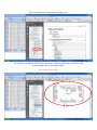
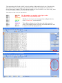
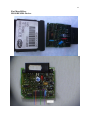
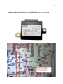
U N LOC K IN G TEC H N OLOGY
U s e r
M a nua l
w w w . a d v a n c e d - d i a g n o s t i c s . c o m
™
CodeX-Lite Adapter List
A.
B.
C.
1.
2.
3.
4.
5.
6.
7.
8.
9.
10.
11.
12.
13.
14.
15.
16.
17.
18.
19.
20.
TMS 370 Adapter
Motorola HC912—9S12 Adapter
Programmer.
EEPROM 93CXX, 24CXX, 25XXX, M35080
Motorola MC68HC11P2+MC68HC11PH8-PLCC84
Motorola MC68HC08AS-PLCC52
Motorola MC68HC11KA2/4+MC68HC11KS-PLCC68
Motorola MC68HC(9)08-QFP64
Motorola MC68HC11F1-PLCC68
Motorola MC68HC05H12-PLCC52
Motorola MC68HC11K-PLCC84
Motorola MC68HC11A8/E1/E9/E20+MC68HC11EA9-PLCC52
Motorola MC68HC11KA2/4+MC68HC11PA8-QFP64
Motorola MC68HC11K-QFP80
Programmer to hook, or solder cable. In circuit reading.
Motorola MC68HC11A8/E1/E9/E20-QFP64
Motorola MC68HC05B4/B6/B8/B16/B32+MC68HC705B16/B32-PLCC52
Motorola MC68HC(7)05E6-SOIC28
Motorola MC68HC05B4/B6/B8/B16/B32+MC68HC(7)05X16/X32-QFP64
Motorola MC68HC(9)12B32-MC68HC(9)12D60(A)-QFP80
Motorola MC68HC11F1-QFP80
Motorola MC68HC11L6-PLCC68
8 Pin SOIC Clip & Cable
A
1
2
3
B
8
9
10 11
C
15 16 17 18 19 20
4
5
6
7
12 13 14
Software Installation Instructions.
Insert the Software CD into the laptop CD drive.
Open the “Uuprog” folder
Run the “Setup” Icon.
Copy the “uuprog.lic” file and paste it in C:\Program files\Elrasoft\UPA-USB Suite\Device
programmer.
Plug the USB cable into the PC and connect the Programmer.
When the New Hardware wizard starts, follow the instructions below.
2
3
Your CodeX Lite is now ready to use
Software Operating Instructions
1.
2.
1.
2.
3.
Connect programmer to computer USB using the leads provided
Double click the “Uuprog icon” on desktop screen.
Select device type.
Load device into relevant adapter (make sure it is clean)
Click on program and follow the on-screen prompts.
Basic Advise
1.
2.
3.
4.
5.
Before removing a chip, mark which way round it is fitted
Always save the original file before overwriting the chip. If possible
read the original chip, put it somewhere safe, and use a new chip.
When the job is complete, keep the original chip for another job.
Do NOT use excess force when removing chips.
Before re-soldering ensure that the chip is located correctly on the
pads.
Make sure that the device is clean and remove excess solder from legs
before attempting to read or program.
5
HEXIDECIMAL. How it works.
Hex is just counting in base 16 instead of Decimal which is base 10. ie.
Decimal
= 00 01 02 03 04 05 06 07 08 09 10
Hexidecimal = 00 01 02 03 04 05 06 07 08 09 0A OB OC OD OE OF -
10
When you look at a screen dump of a chip you will have address lines down the left hand side i.e.
0000
0010
0020 20 21 22 23 24 25 26 27 28 29 2A 2B 2C 2D 2E 2F
0030
To find an address simply count across the page.
0 1
2
3 4
5 6 7 8 9 A B C D E F
Address
Bar
Hexidecimal
Data
Ascii
Data
Address Bar. This is used to locate a particular address. For Example 1DC =
It is important to understand that the data displayed in the Hex data column is identical to the data in the Ascii
column. It is just in a different language.
Using the help files to read devices in circuit
Select “Help”, then “Contents.
Select the “+” sign next to UUSP (UPA USB) Serial Programmer
Next, select the type of device that you are going to read. E.g. Motorola HCS12
Now select the device type that you wish to read
The program will display the device pin schematic, showing which pins to connect to the
programming cable or microhook cable.
Pin colours on next page
The connecting cable for the CodeX in circuit reading or Microhooks, has 9 pins. Using the help
information on the previous pages, the schematics give you the pin numbers to connect to the
device that you are reading. The cables that we supply are colour coded for ease when using them
on control modules which we have put into the manual.
The colours of the wires are listed below.
PIN 1
PIN 2
PIN 3
PIN 4
PIN 5
PIN 6
PIN 7
PIN 8
PIN 9
BROWN The Pin numbers are marked on the 9 pin socket
RED
attached to the programming cable.
ORANGE
Should you receive an error message when reading the device,
YELLOW
select “connections” as shown below.
GREEN
BLUE
This will then display a list of the pins, and their connection
PURPLE
status. The example below is all good, but a bad connection will
GREY
be marked “bad” and displayed in red.
BLACK
88
Alfa Romeo/ Fiat/Lancia Body Module
MC68HC912DG128 Device.
84
Fiat Marelli Box.
MC68HC05E6 Device.
83
Fiat Magneti Marelli immobilizer box. MC68HC08AZ32 device. 64 pin QFP
85
Fiat 500, Grande Punto Body module
Device is 93C86. Remove the back of the BSI case. No need to remove fuses.
Vito / Sprinter WSP Box.
Mask Set J66D—MC68HC08AZ32A Device
Mask Set J74Y— MC68HC908AS60 Device
88
87
Mercedes Sprinter / Vito. WSP.
Device = MC68HC08AZ32A
Mask Set L52H
36
Secured Sprinter/Vito WSP Box.
If you read a WSP with the L52H mask set, and the read is all AD, then the device is secured. Follow the
procedure below to read the device correctly.
Enter the following security bytes into the 8 spaces:F1 6A FA 04 E4 DA FA 04.
Then select “auto baud rate”
Then “Read”.