1
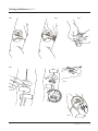
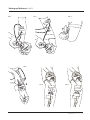
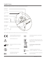
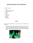
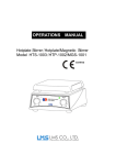
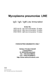
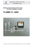
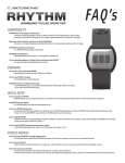
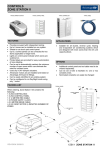
HOME/SELF USE
User Manual
US English
Alarm unit & Sensor patch
Instructions for use
Alarm unit & Sensor patch
US English version
© 2010 Redsense Medical AB
P.O Box 287
SE-301 07 Halmstad
www.redsensemedical.com
Redsense Medical INC
150 N. Michigan Avenue, Suite 1950
Chicago, IL 60601, US
Phone: +1 877 733 0830
Fax: +1 312 276 8606
RM-1-RM129 July 2010
Caution:
Federal (US) law restricts this
device to sale by or on the
order of a licensed practitioner.
Instructions for use
Warnings and Precautions
About the Redsense alarm system
Setting up Redsense
While dialysis is in progress
After the dialysis is complete
Maintenance
Cleaning
Charging the battery
Changing the battery
Figures 2-7
Figures 8-13
Figures 14-17
Symbols and terms
3
3
4
4
5
5
5
5
5
6
7
8
9
Intended use
The Redsense device is intended to monitor for potential blood loss from the hemodialysis access site in hemodialysis patients
undergoing hemodialysis treatment up to 5 hours at home or in the clinical setting. The device includes a blood sensor incorporated
into an adhesive dressing. The sensor monitors potential blood leakage from the needle puncture via an infrared light and will
alarm if needle dislodgement or blood leakage is detected. All use must be administrated under physician’s prescription, and
must be observed by a trained and qualified person considered to be competent in the use of this device by the prescribing physician.
Instructions for use Alarm unit & Sensor patch 02
Warnings and Precautions
About the Redsense alarm system
• The Redsense - device is intended to monitor for
potential blood loss from the hemodialysis access site
in hemodialysis patients undergoing hemodialysis
treatment up to 5 hours at home or in the clinical
setting.
Redsense is a system for monitoring the vein needle
during hemodialysis. Redsense consists of an alarm unit
and a sensor patch (see Fig. 1). Once the sensor patch
has been placed over the vein needle it detects blood
that comes into contact with the sensor patch. This can
occur if the needle has been accidentally pulled out or if
there is a blood loss during dialysis.
• The device includes a blood sensor incorporated into
an adhesive dressing. The sensor monitors potential
blood leakage from the needle puncture via an infrared
light and will alarm if needle dislodgement or blood
leakage is detected.
• All use must be administrated under physician’s
prescription, and the patient using the device at home
must be considered to be competent in the use of this
device by the prescribing physician.
FIG. 1
Alarm unit
• All use must be observed by a trained and qualified
person, considered to be competent in the use of
this device by the prescribing physician.
• Before use a test must be performed to make sure the
patient and the observing person can clearly
hear the alarm signal. The test is further described at
page 6 under point 9.
• Redsense must be used only for its intended purpose
and in accordance with these instructions.
All other use is not allowed.
• The device must only be attached to the patient as
shown in instruction for use and the user manual.
• Read and follow all instructions for use carefully.
Sensor patch
• Redsense has been tested and is approved in accor
dance with the IEC 60601-1-2:2007 and IEC 610006-1:2007 standard concerning electromagnetic compatibility (EMC). Redsense requires special precautions
regarding EMC and consequently has to be employed
in conformance with the EMC information detailed in
these instructions. Portable and mobile RF communications equipment may affect Redsense.
• This device should not be relied upon as the sole
monitor for blood loss/needle disconnection at the
vascular access site.
Warnings and Precautions
• Redsense is not for nocturnal use.
Instructions for use Alarm unit & Sensor patch 03
Setting up Redsense
Redsense should be placed on your arm after the insertion
of the needles and prior to the start of dialysis. Redsense
must be switched on for the entire duration of the dialysis.
The alarm unit can be fasten as follows:
Fasten the alarm unit with the clip at a maximum distance
of 25 cm from the needle with the sockets turned towards
the sensor patch. You can also fasten the alarm unit with a
Velcro strip which is optional. Fig. 2 shows the alarm unit
fastened onto the upper arm with the clip. It is also
possible to fasten the alarm unit onto the lower arm and
turn it to face in the opposite direction. Fig. 3 shows the
alarm unit fastened onto the upper arm using the Velcro
strip. Do not tighten the Velcro strip too hard due to
possible compression of access vessels. It is also possible
to fasten the alarm unit to your shirt pocket.
1. Fasten the Velcro strip to your upper or lower arm if the
Velcro strip is being used.
2. Remove the sensor patch from its pack Fig. 4 The
sensor patch must be labelled “Redsense”. Ensure that
the sensor patch is not mechanically damaged.
3. Completely clean the area around the needle so that
any fluid, blood, residual cleaning fluid, lotion, etc. is
fully removed.
4. Apply the sensor patch to the skin over the needle
with the absorbent part of the patch centered over
the puncture Fig. 5. Make certain that the sticky part
of the patch does not cover the wings. Fig. 6 shows
how the sensor should be placed in position.
5. Fasten the needles in place in the normal way by
using tape or something equivalent.
6. Connect the sensor patch cable to the alarm unit by
pressing the connector into the socket until a click is
heard (Fig. 7 & Fig. 8). For use with upper arm fistula
see Fig. 9.
7. Fasten the alarm unit with the clip (Fig. 10). For use
with upper arm fistula see Fig. 11.
8. If necessary, tape can be used to stick the sensor patch
and/or the sensor cable down. Fig. 12-13 show how the
fibre optic cables of the sensor patch can be fastened
to your arm.
9. Press the on button once to start the test of the alarm
signal and the 4 LED. (Fig. 14-15) Confirm that all 4 LED
are lit and clearly can be indicated. Confirm that the
patient and the observing person can clearly hear the
alarm signal. The observing person must be sure that
the alarm signal can be heard from other rooms or
while there is noise in the house. The observing person
must be situated at places where the alarm signal can
be heard during the entire dialysis treatment. The alarm
signal test will continue until the button is pressed
again.
10. To stop the test of the LED and alarm signal press the
start button once again. The green light starts to blink
for a few seconds before becoming completely lit.
When the green light is completely lit, the alarm is
operational, the monitoring is functioning in the
correct way and the dialysis can begin. The green light
blinking indicates that the alarm unit is performing a
test. During this test there are three conditions that
may need to be addressed. These are shown by the
following lights and symbols being illuminated:
• The yellow light, marked by the battery symbol,
denotes that the battery does not have sufficient
capacity left for a 5 hours dialysis session and should be
recharged. See the later section on maintenance about
charging the battery.
• The yellow light, marked by a warning symbol signifies
one of the following situations: There is moisture on
the sensor. The sensor is not correctly connected. The
sensor is defect.
• If all LEDs are blinking this means that an internal
software error has been detected, please contact
Redsense Medical for further support.
Any problems should be dealt with before a new attempt
is made to start the alarm unit. If blood or moisture has
come into contact with the sensor, it must be replaced by
a new one. If any other technical problem appears do not
use the Redsense unit, please contact Redsense Medical
for further support.
While dialysis is in progress
During operation the green light is completely lit and you
may observe the following:
• The red light accompanied by a continuous two-toned
alarm signal indicates that blood has dripped onto the
sensor either because the needle has been pulled out
or there has been a leakage. In this event, firstly, deal
with the reason for the leakage and then switch off the
alarm by holding the button pressed in for one second.
• The yellow battery warning light accompanied by an
intermittent alarm signal signifies that the battery
capacity has become too low meaning that the
monitoring can no longer be performed correctly. In
this case, switch off the alarm unit by pressing and
holding in the button and then replace it with
a fully-charged unit.
• The yellow warning light accompanied by an intermit
tent alarm signal indicates one of the following:
Moisture has come into contact with the sensor. The
sensor has come loose or broken down.
Instructions for use Alarm unit & Sensor patch 04
While dialysis is in progress (cont.)
Charging the battery
Switch off the alarm by holding the button pressed in and
continue the dialysis without monitoring the needle or
change to a new sensor patch and start again.
The battery should only be charged when the alarm unit is
not in use and is not attached to your arm. A fully-charged
battery lasts 15-20 hours meaning that it is advisable to
charge the battery after each dialysis treatment, depending on the duration of the treatment.
• All LEDs blinking accompanied by an intermittent alarm
signal indicates an internal software error, please
contact Redsense Medical for further support.
Switch off the alarm unit by holding the button pressed in
and continue the dialysis without monitoring the needle,
please contact Redsense Medical for further support.
1. Connect the charger to the alarm unit using the cable.
The charger must be labeled “Redsense”. Note that the
sensor should not be connected at the same
time (Fig.17).
2. Plug the charger into a socket outlet (100 - 240 V).
After the dialysis is complete
3. The yellow light blinks while charging is in progress.
1. Hold the button pressed down for one second in order
to switch off the alarm.
2. Remove the sensor patch from your arm.
4. When the green light is illuminated, the battery is fully
charged. This can take up to 6 hours.
3. Remove the alarm unit.
4. Disconnect the sensor patch from the alarm unit and
dispose it along with the other waste material from the
dialysis.
5. Clean the alarm unit according to the maintenance
instructions.
Note: The alarm can also be switched off at any time during
an ongoing dialysis.
Maintenance
Cleaning
The sensor patch itself is disposable and must not be
cleaned for re-use.
Changing the battery
In order to change the battery, the alarm unit must be
opened up and therefore this should only be done when
the unit is being serviced. Service must be performed by
personnel authorized by Redsense Medical.
Internal memory
Redsense alarm unit has an internal memory that stores
data on the last treatments. The internal memory is
accessed using the communications port. The internal
memory must only be accessed by personnel authorized by
Redsense Medical.
The alarm unit should be wiped off with appropriate
disinfectant after every use. Either an alcohol based
disinfectant, using a slightly damp cloth, or pads saturated
with alcohol based disinfectant can be used. If blood has
come into contact with the alarm unit, the unit must be
cleaned carefully to avoid biohazards. DO NOT use Alcalic
detergents as they may damage the plastic shell of the
alarm unit.
If using the Velcro strip, the Velcro strip is personal and
must only be used by you.
Printable surface
If any kind of information needs to be written on the alarm
unit Fig. 16 shows the surface intended for this purpose.
Use a marker or similar.
If the written information needs to be removed or
changed it can be wiped off using a damp cloth dipped in
alcohol.
Instructions for use Alarm unit & Sensor patch 05
Setting up Redsense Fig 2-7
FIG. 3
FIG. 2
FIG. 4
FIG. 5
YES
YES
FIG. 6
NO
FIG. 7
Instructions for use Alarm unit & Sensor patch 06
Setting up Redsense Fig 8-13
FIG. 8
FIG. 9
FIG. 10
FIG. 11
FIG. 12
FIG. 13
Instructions for use Alarm unit & Sensor patch 07
Setting up Redsense Fig 14-17
FIG. 14
FIG. 15
FIG. 16
FIG. 17
Printable surface
Instructions for use Alarm unit & Sensor patch 08
Symbols & terms
The following symbols and terms are used in this manual and on the product:
Red light and
alarm symbol
On / off button
Communications
port
Yellow light and
battery symbol
Green light and
working symbol
Yellow light and
warning symbol
Socket for the
sensor fiber
optic cable
Socket for battery
charger
Other symbols displayed on the product and its accessories indicate the following:
The product fulfills the requirements in
93/42 EEC (Medical Device Directive)
Lot number including year of manufacture
(Sensor patch)
Consult Instructions for use
User part Type BF- Body Floating (the surface
between the device and the patient does not
conduct electricity)
Redsense
Medical AB
Halmstad
Sweden
The alarm unit is covered by the WEEE
directive, therefore it must be recycled.
(Alarm unit)
Manufactured by Redsense Medical AB
Sweden
Only for single use (Sensor patch)
Last date for use of the sensor. In this
example year 2008 month 9. (Sensor patch)
EXP. 2008-09
Serial number, including year of
manufacture (Alarm unit)
STERILE EO
The sensor has been sterilized using Ethylene
Oxide (Sensor patch).
Instructions for use Alarm unit & Sensor patch 09