1
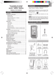
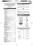
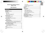
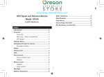
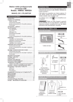
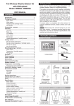
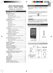
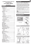
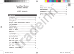
USB Weather Station Kit
Model: WMRS200
USER MANUAL
EN
USB Weather Station Kit
Model: WMRS200
INTRODUCTION
Thank you for selecting the Oregon ScientificTM USB
Weather Station Kit (WMRS200).
USER MANUAL
With easy PC uploading capability via USB, the USB
Weather Station Kit (WMRS200) displays the collected
weather data on your PC in a convenient and intuitive
way.
CONTENTS
INTRODUCTION ....................................................... 1
PACKAGING CONTENTS ........................................ 1
The weather station is capable of connecting to a PC
computer using the USB connection. The software
can read the latest weather data collected from the
base station. Please download the software from the
following website:
USB Communications Hub .................................... 1
Wind Sensor / Temperature & Humidity Sensor .... 2
Rain Gauge ............................................................ 2
Assembly Parts ...................................................... 2
ACCESSORIES - SENSORS.................................... 2
http://10.1.6.110/wmrs200.exe
OVERVIEW ............................................................... 2
For full details see the software instructions.
Front View .............................................................. 2
Back View .............................................................. 2
PC System requirements
The minimum system requirements for use of the
software is:
• Operating system: Microsoft Windows 98 or above
• Processor: 300 MHz or above CPU speed
• RAM: Min. 128Mb
• Hard disk free space: Min. 50Mb
• CD-ROM or DVD drive
Wind Sensor .......................................................... 3
Rain Gauge ............................................................ 3
Outdoor Temperature / Humidity Sensor ............... 3
GETTING STARTED ................................................. 3
Set Up Remote Wind Sensor................................. 3
Set Up Remote Temperature / Humidity Sensor .... 4
REMOTE UNIT ASSEMBLY ..................................... 4
The USB communications hub is compatible with
other sensors. To purchase additional sensors, please
contact your local retailer.
Remote Wind Sensor on Existing Pole .................. 4
Temperature/Humidity Sensor Mounted Separately ... 4
Set Up Rain Gauge................................................ 4
Sensors with this logo
unit.
GETTING STARTED ................................................. 5
Set Up USB Communications Hub ........................ 5
are compatible with this
NOTE Please keep this manual handy as you use
your new product. It contains practical step-by-step
instructions, as well as technical specifications and
warnings you should know about.
Sensor Data Transmission ..................................... 5
VIEW READINGS ON PC ......................................... 5
To disable sleep mode on PC ................................ 5
RESET....................................................................... 6
TROUBLE SHOOTING ............................................. 6
PACKAGING CONTENTS
SPECIFICATIONS ..................................................... 6
USB COMMUNICATIONS HUB
PRECAUTIONS ........................................................ 7
ABOUT OREGON SCIENTIFIC ................................ 7
EU-DECLARATION OF CONFORMITY ................... 7
FCC STATEMENT ..................................................... 7
1 x USB cable
1 x USB Communications Hub
1
EN
WIND SENSOR / TEMPERATURE &
HUMIDITY SENSOR
•
•
Thermo-hygro THGR810 (10-Ch)
UV UVN800
* Features and accessories will not be available in all
countries.
OVERVIEW
2 x AA UM-3
1.5V batteries
1 x Wind Sensor
(1 x Wind Vane
Above and 1 x
Anemometer
Below)
FRONT VIEW
1
1 x Aluminium
pole
2 x AAA UM-4
1.5V batteries
2
3
4
5
4 x Screws
(Type C)
1 x Temperature /
Humidity Sensor
casing
1 x Temperature
/ Humidity
Sensor
1 x sensor
connector
RAIN GAUGE
1 x Filter
1 x Rain
Collector
2 x AA UM-3
1.5V batteries
1. Indicates a successful USB connection / Unit is
ON
2. Indicates Wind Sensor reception status
3. Indicates Outdoor Thermo-Hygro Sensor reception
status
4. Indicates Rain Gauge reception status
5. Indicates UV Sensor reception status
4 x Screws
(Type C)
BACK VIEW
6 X Washers
ASSEMBLY PARTS
1
2
1 x Horizontal
Attachment
Bracket
1 x Versatile
Base (Wall or
Ground Fixable)
3
2 x Round
U- bolts
ACCESSORIES - SENSORS
This product can work with up to 10 sensors at any one
time to capture outdoor temperature, relative humidity
or UV readings in various locations.
4
Optional wireless remote sensors such as those
listed below can be purchased separately. For more
information, please contact your local retailer.*
•
•
Solar Panel STC800 connectable to Wind Sensor
and Temperature / humidity sensor
Thermo-hygro THGR800 (3-Ch)
1.
2.
3.
4.
2
SEARCH: Initiate search for remote sensors
RESET: Reset unit to default settings
Battery compartment
USB socket: Upload records to PC / charge
rechargeable battery
OUTDOOR TEMPERATURE / HUMIDITY
SENSOR
1
2
4
1
3
1.
2.
3.
4.
Wind direction
Wind vane casing
Anemometer
Solar power socket
3
2
4
RAIN GAUGE
Base and funnel:
1
1.
2.
3.
4.
2
3
Temperature / humidity sensor casing
Solar power socket
RESET button
Battery compartment
GETTING STARTED
SET UP REMOTE WIND SENSOR
The wind sensor takes wind speed and direction
readings.
1. Rain Gauge
2. Battery compartment
3. RESET button
The sensor is battery operated. It is capable of
transmitting data to the USB communications hub
wirelessly within an approximate operating range of
100 meters (328 feet).
IMPORTANT Ensure that the wind sensor is pointing
North to enable it to record accurate readings.
1
NOTE The sensor should be positioned in an open
area away from trees or other obstructions.
To insert batteries:
2
2
1
1. Funnel
2. Indicator
3
1. Unscrew the anemometer from the wind sensor
carefully.
2. Insert batteries matching the polarities (+ / -) and
replace the anemometer. Press RESET after each
battery change.
EN
WIND SENSOR
EN
2. Insert the horizontal attachment bracket into the
base.
3. Using a screw, fix firmly into place.
6
16
4
3
3. Slide wind vane onto the end of the plastic
attachment located on the aluminium pole.
5
NOTE Use alkaline batteries for longer usage and
consumer grade lithium batteries in temperatures
below freezing.
4. Insert wind sensor into the top of the bracket.
5. Using screws, fix aluminium pole firmly into place.
6. Slide outdoor sensor onto bracket.
SET UP REMOTE TEMPERATURE /
HUMIDITY SENSOR
IMPORTANT For best results, point the wind vane
North.
2
3
1
1. Holding sensor, twist and click to the left.
2. Pull sensor away from casing.
3. Insert batteries matching the polarities (+ / -). Press
RESET after each battery change.
TEMPERATURE / HUMIDITY SENSOR
MOUNTED SEPARATELY
1. Insert 4 type A screws into the holes of the sensor
connector. Screw firmly into place, i.e., fence.
5
4
4. Insert sensor into the casing, twist and click to the
right to secure.
5. Slide temperature and humidity sensor onto the
smaller end of the sensor connector.
SET UP RAIN GAUGE
REMOTE UNIT ASSEMBLY
The rain gauge collects rain and takes readings of
rainfall rate and the total rainfall over a period of time.
The sensor can remotely transmit data to the USB
communications hub.
REMOTE WIND SENSOR ON EXISTING POLE
3
The USB communications hub and rain gauge should
be positioned within an effective range: about 100
meters (328 feet) in an open area.
1
The rain gauge should be mounted horizontally about
1 meter (3 feet) from the ground in an open area away
from trees or other obstructions to allow rain to fall
naturally for an accurate reading.
2
1. Secure the plastic base onto existing pole with Ubolts, washers and bolts.
4
GETTING STARTED
SET UP USB COMMUNICATIONS HUB
NOTE Install batteries matching the polarities (+
/ -) in the remote sensors before installing the USB
communications hub.
2
1
For continuous use, connect the USB communications
hub to computer using USB cable provided. A
rechargeable battery is included for back-up use only.
1. Remove screws and slide the cover off in an
upwards motion.
2. Insert the batteries (2 x UM-3 / AA), matching the
polarities (+ / -). Press RESET after each battery
change.
NOTE Batteries should not be exposed to excessive
heat such as sunshine or fire.
3
SENSOR DATA TRANSMISSION
To search for a sensor:
Press and hold SEARCH located at the back of USB
communications hub.
3. Remove the fibre tape.
To ensure a level plane:
Put a few drops of water on the cross at the base of the
funnel to check the horizontal level.
Icons will flash during search
mode.
Continuous display of icons indicate that the respective
remote sensor has been successfully logged.
NOTE Unit will search only for already registered
sensor or new sensor reset within last 30 minutes. To
register a new sensor, reset sensor prior to search.
1
3
2
TIP The transmission range may vary depending
on many factors. You may need to experiment with
various locations to get the best results.
4
VIEW READINGS ON PC
Water will pool to the center of the cross when the rain
gauge is level.
To upload records to PC:
Plug USB and upload onto computer.
For your convenience, rechargeable battery will
automatically be charged.
If water remains on 1-4, the gauge is not horizontal.
If necessary, adjust the level using the screw.
NOTE PC program must be installed before uploading
of records from USB communications hub.
IMPORTANT Ensure sleep mode on computer is
disabled as this will adversely affect the operation of
this unit.
TO DISABLE SLEEP MODE ON PC
1. Right Click on Desktop.
2. Choose Properties.
3. Click on “Screen Saver” Tab in the “Display
Properties” window.
4. Click on “Power” located on bottom half of window.
5. A new window “Power Options Properties” will
open.
NOTE For best results, ensure the base is horizontal
to allow maximum drainage of any collected rain.
5
EN
To set up the Rain Gauge:
EN
6. Under “System standby” option, choose “Never” in
drop down menu.
7. Click “Apply” and then click “OK”.
8. Previous window will return. Click “OK” to confirm
and exit.
INDOOR RELATIVE HUMIDITY
Displayed range
Operating range
Resolution
Accuracy
RESET
Press RESET to return to the default settings.
Comfort
Memory
Alarm
TROUBLE SHOOTING
PROBLEM
SYMPTOM
Sensor
Icons
are
displayed.
PC
not
Cannot upload
REMEDY
REMOTE WIND SENSOR UNIT
1. Check
sensor
batteries
2. Check if sensors
are within range
3. Check
USB
communications
hub is connected
to USB
Dimensions
(L x W x H)
Weight
Wind speed unit
Speed accuracy
Direction accuracy
Transmission of
wind speed signal
Memory
Battery
1. Check the PC
software is setup
and running
2. Check PC is
connected
with the USB
communications
hub via USB
Dimensions
(L x W x H)
Weight
Temp. unit
Displayed range
Operating range
Accuracy
USB COMMUNICATIONS HUB
68 x 46 x 136 mm
(2.7 x 1.8 x 5.4 inches)
92 g (0.2 lbs) without battery
Comfort
Memory
INDOOR BAROMETER
Barometer unit
Measuring range
Accuracy
Resolution
Altitude setting
Weather display
Memory
mb/hPa, inHg and mmHg
700 – 1050mb/hPa
+/- 10 mb/hPa
1mb (0.0 inHg)
Sea level
User setting for compensation
Sunny, Clear night, Partly Cloudy,
Cloudy, Cloudy at night, Rainy
and Snowy
Historical data and bar chart for
last 24hrs
Comfort
Memory
Alarm
Max speed gust
2 x UM-3 (AA) 1.5V batteries
115 x 87 x 118 mm
(4.5 x 3.4 x 4.6 inches)
130 g (0.286 lbs) without battery
°C / °F
-50°C to 70°C (-58°F to 158°F)
-30°C to 60°C (-4°F to 140°F)
-20°C – 0°C: +/- 2°C (+/- 4.0°F)
0°C - 40°C: +/- 1°C (+/- 2.0°F)
40°C - 50°C: +/- 2°C (+/- 4.0°F)
50°C - 60°C: +/- 3°C (+/- 6.0°F)
20°C to 25°C (68°F to 77°F)
Current, Min and Max temp.
Dew Point w/ Max and Min
Wind chill temp. and min
RELATIVE HUMIDITY
Displayed range
Operating range
Resolution
Accuracy
Comfort
Memory
Battery
INDOOR TEMPERATURE
Temp. unit
Displayed range
Operating range
Accuracy
178 x 76 x 214 mm
(7 x 3 x 8.4 inches)
100 g (0.22 lbs) without battery
m/s, kph, mph, knots
2 m/s ~ 10 m/s (+/- 3 m/s)
10 m/s ~ 56 m/s (+/- 10%)
16 positions
Approx. every 14 seconds
OUTDOOR TEMPERATURE / HUMIDITY UNIT
RELATIVE TEMPERATURE
SPECIFICATIONS
Dimensions
(L x W x H)
Weight
2% to 98%
25% to 90%
1%
25% - 40%: +/- 7%
40% - 80%: +/- 5%
80% - 90%: +/- 7%
40% to 70%
Current, Min and Max
Hi / Lo
°C / °F
0°C to 50°C (32°F to 122°F)
-30°C to 60°C (-4°F to 140°F)
0°C - 40°C: +/- 1°C (+/- 2.0°F)
40°C - 50°C: +/- 2°C (+/- 4.0°F)
20°C to 25°C (68°F to 77°F)
Current, Min and Max temp.
Dew Point w/ Min and Max
Hi / Lo
2% to 98%
25% to 90%
1%
25% - 40%: +/- 7%
40% - 80%: +/- 5%
80% - 90%: +/- 7%
40% to 70%
Current, Min and Max
2 x UM-4 (AAA) 1.5V batteries
RF TRANSMISSION
RF frequency
Range
Transmission
No. of Channel
6
433MHz
Up to 100 meters (328 feet) with
no obstructions
Approx. every 60 seconds
1 for Wind/ Rain/ UV and 10 for
Temp. / Humidity
EU-DECLARATION OF CONFORMITY
Dimensions
Hereby, Oregon Scientific, declares that this USB
Weather Station Kit (models: WMRS200) is in
compliance with the essential requirements and other
relevant provisions of Directive 1999/5/EC. A copy
of the signed and dated Declaration of Conformity
is available on request via our Oregon Scientific
Customer Service.
Weight
Rainfall unit
Range
Resolution
Accuracy
Memory
Battery
107 x 87 x 56 mm
(L x W x H) (4.2 x 3.4 x 2.2 inches)
134 g (0.3 lbs) without battery
Mm/hr and in/hr
0 mm/hr – 999 mm/hr
1 mm/hr
< 15 mm/hr: +/- 1 mm
15 mm to 9999 mm: +/- 7%
Past 24hrs, hourly and
accumulated from last memory
reset
2 x UM-3 (AA) 1.5V
COUNTRIES RTTE APPROVAL COMPLIED
All EU countries, Switzerland CH
and Norway N
PRECAUTIONS
•
•
•
•
•
•
•
•
•
•
•
•
Do not subject the unit to excessive force, shock,
dust, temperature or humidity.
Do not cover the ventilation holes with any items
such s newspapers, curtains etc.
Do not immerse the unit in water. If you spill liquid
over it, dry it immediately with a soft, lint-free cloth.
Do not clean the unit with abrasive or corrosive
materials.
Do not tamper with the unit’s internal components.
This invalidates the warranty.
Only use fresh batteries. Do not mix new and old
batteries.
Images shown in this manual may differ from the
actual display.
When disposing of this product, ensure it is
collected separately for special treatment.
Placement of this product on certain types of
wood may result in damage to its finish for which
Oregon Scientific will not be responsible. Consult
the furniture manufacturer’s care instructions for
information.
The contents of this manual may not be reproduced
without the permission of the manufacturer.
Do not dispose old batteries as unsorted municipal
waste. Collection of such waste separately for
special treatment is necessary.
Please note that some units are equipped with a
battery safety strip. Remove the strip from the
battery compartment before first use.
FCC STATEMENT
This device complies with Part 15 of the FCC Rules.
Operation is subject to the following two conditions: (1)
This device may not cause harmful interference, and
(2) This device must accept any interference received,
including interference that may cause undesired
operation.
WARNING Changes or modifications not expressly
approved by the party responsible for compliance could
void the user’s authority to operate the equipment.
NOTE This equipment has been tested and found
to comply with the limits for a Class B digital device,
pursuant to Part 15 of the FCC Rules. These limits
are designed to provide reasonable protection against
harmful interference in a residential installation.
This equipment generates, uses and can radiate radio
frequency energy and, if not installed and used in
accordance with the instructions, may cause harmful
interference to radio communications. However, there
is no guarantee that interference will not occur in a
particular installation. If this equipment does cause
harmful interference to radio or television reception,
which can be determined by turning the equipment
off and on, the user is encouraged to try to correct
the interference by one or more of the following
measures:
• Reorient or relocate the receiving antenna.
• Increase the separation between the equipment
and receiver.
• Connect the equipment into an outlet on a
circuit different from that to which the receiver is
connected.
• Consult the dealer or an experienced radio / TV
technician for help.
NOTE The technical specifications for this product
and the contents of the user manual are subject to
change without notice.
ABOUT OREGON SCIENTIFIC
Visit our website (www.oregonscientific.com) to learn
more about Oregon Scientific products. If you’re in
the US and would like to contact our Customer Care
department directly, please visit:
www2.oregonscientific.com/service/support
OR
Call 1-800-853-8883.
DECLARATION OF CONFORMITY
The following information is not to be used as contact
for support or sales. Please call our customer service
number (listed on our website at www.oregonscientific.
com), or on the warranty card for this product) for all
inquiries instead.
For international inquiries, please visit:
www2.oregonscientific.com/about/international
7
EN
REMOTE RAIN GAUGE
EN
We
Name:
Address:
Telephone No.:
Oregon Scientific, Inc.
19861 SW 95th Ave.,Tualatin,
Oregon 97062 USA
1-800-853-8883
declare that the product
Product No.:
WMRS200
Product Name:
USB Weather Station Kit
Manufacturer:
IDT Technology Limited
Address:
Block C, 9/F, Kaiser Estate,
Phase 1,41 Man Yue St.,
Hung Hom, Kowloon,
Hong Kong
is in conformity with Part 15 of the FCC Rules.
Operation is subject to the following two conditions:
1) This device may not cause harmful interference.
2) This device must accept any interference received,
including interference that may cause undesired
operation.
8
© 2008 Oregon Scientific. All rights reserved.
086L005303-015