1
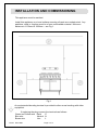
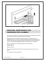
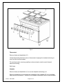
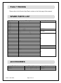
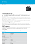
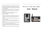
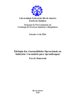
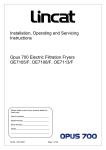
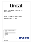
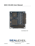
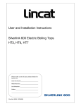
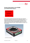
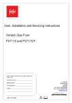
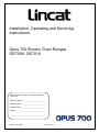
Installation, Operating and Servicing Instructions Opus 700 Electric Oven Ranges OE7008, OE7010 Please make a note of your product details for future use: Date Purchased:_________________________ Model Number:__________________________ Serial Number:__________________________ Dealer:_________________________________ _______________________________________ IS 397 ECN 3607 Page 1 of 11 CONTENTS Important Information Warnings and Precautions Technical Data Checklist of Enclosures Installation and Commissioning Operating Instructions Cleaning Servicing, Maintenance and Component Replacement Fault Finding Spare Parts List Accessories Service Information and Guarantee 2 3 3 3 4-5 5-6 6-7 7-9 10 10 10 11 IMPORTANT INFORMATION Read these instructions carefully before using this product, paying particular attention to all sections that carry warning symbols, caution symbols and notices. Ensure that these are understood at all times. WARNING! This symbol is used whenever there is a risk of personal injury. CAUTION! This symbol is used whenever there is a risk of damaging your Lincat product. NOTE: This symbol is used to provide additional information, hints and tips. KEEP THIS MANUAL FOR FUTURE REFERENCE IS 397 ECN 3607 Page 2 of 11 WARNINGS AND PRECAUTIONS This appliance must be installed, commissioned and serviced by a qualified person in accordance with national and local regulations in force in the country of installation. If the supply cord is damaged, it must be replaced by the manufacturer, its service agent or similarly qualified person. Ensure that the plug/socket is accessible at all times. Strip plastic coating and clean the appliance before use. During operation parts may become hot - avoid accidental contact. Disconnect this appliance before servicing, maintenance or cleaning. TECHNICAL DATA OE7008 Height (mm) Width (mm) Depth (mm) Weight (kg) Oven Rating (kW) Hob element – individual (kW) 950 900 Amps 3N~ T Total power rating (kW) 600 803 Total power rating @ 400V 3 phase (kW) Fan rating (W) Voltage 3N~ OE7010 155.0 6.0 2.6 Phase 1 Phase 2 Phase 3 2 x 32 Phase 1 Phase 2 Phase 3 21.6 7.2 7.2 7.2 31A 31A 31A CHECK LIST OF ENCLOSURES Warranty card Instructions manual Wire shelves IS 397 ECN 3607 Page 3 of 11 112.0 4.0 2.6 Phase 1 4.0 Phase 2 5.2 Phase 3 5.2 32 Phase 1 17.4A Phase 2 22.6A Phase 3 22.6A 14.4 INSTALLATION AND COMMISSIONING This appliance must be earthed. Install this appliance on a level surface ensuring all vents are unobstructed. Any partitions, walls or furniture must be of non-combustible material. Minimum distances A 100mm B 1000mm – see Fig 1. Fig 1 An equipotential bonding terminal is provided to allow cross bonding with other equipment. If replacing the plug connect the terminals as follows: Green and Yellow wire Earth E Blue wire Neutral N Brown wire Live L IS 397 ECN 3607 Page 4 of 11 Means of isolation with at least 3mm contact separation in all poles must be incorporated into the fixed wiring of this appliance. The fixed wiring insulation must be protected by insulated sleeving having a temperature rating of 60 Deg C. Supply cords shall be oil resistant, sheathed flexible cable not lighter than ordinary polychloroprene or equivalent elastomer sheathed cord (code 60245 IEC 57). If this appliance is fitted with castors, use caution at all times when manipulating or moving, and lock castors when appliance is in position. Connection to the electrical supply is made at the rear of the appliance. Remove the protective cover and fit a suitable cable to the strain relief. Connect to the inlet terminal block. This appliance is supplied for connection to a three phase supply. OPERATING INSTRUCTIONS Only qualified or trained personnel should use this appliance. Fig 2 Before using the appliance for the first time, turn the hotplates to full setting for 4 minutes without pans to allow them to cure and harden to maximum durability. IS 397 ECN 3607 Page 5 of 11 Refer to Fig 2 Hotplates Switch on the electricity supply – the green neon (A) illuminates. The hotplates are controlled by 6 position rotary switched controls (E), each marked by an individual hob marker (D). For maximum efficiency, always use good quality pans with lids. Oven operation Switch on at the main supply and check the green neon (A) is illuminated. Set the oven control (B) to the desired temperature. The amber neon (C) will illuminate. The amber neon extinguishes when the set temperature is reached and then cycles as the element maintains the oven temperature. Be aware of the escape of hot air when opening the oven doors. Shutdown After use, turn all control knobs to the ‘Off’ position and switch off the mains electricity supply. CLEANING Do not use a water jet or steam cleaner, and do not immerse this appliance. Clean all panels with warm water and mild detergent, do not use abrasive materials, or products containing either chlorine or hydrochloric acid. Dry with a soft cloth. After cleaning, apply a thin film of vegetable oil to the hotplates. The oven features removable liners for sides, base and top. Slide out the top liner and bottom liner and remove the wire shelves (Fig 3) by pushing to the rear, tilting up at the back then drawing forward. Remove the shelf supports by lifting up to disengage. Lift off each of the side liners. For stubborn deposits, a de-greasing agent ‘Carbon-Off’ is available from Lincat. Replace interior panels correctly after cleaning. IS 397 ECN 3607 Page 6 of 11 Fig 3 SERVICING, MAINTENANCE AND COMPONENT REPLACEMENT All servicing, maintenance and component replacement on this appliance should be carried out by one of our recommended service engineers. Replacement of some components requires removal of the facia panel and heatshield (see Fig 4). Remove the control knobs (A) and all screws beneath the facia (B). Be aware when lowering the facia that electrical connections will still be made. When replacing heatshield and facia ensure cables are not trapped. After any maintenance, check the appliance for electrical safety. Hotplate Switch Remove the facia. Remove faulty switch and transfer wires correctly, ideally one at a time to new switch. Fit new switch to facia and refit facia. IS 397 ECN 3607 Page 7 of 11 Fig 4 Thermostat Remove facia and heatshield (C). Unclip thermostat phial and remove thermostat, keeping the insulated sleeving to reuse on the new thermostat. Fit new thermostat, ensuring capillary is sleeved and routed to avoid internal electrical shorting. Refit facia. Hotplate Remove facia and heatshield (C) to access hotplate restraining nut. Remove restraining nut and press the underside of the hotplate (D) up to facilitate easy removal from above. Access to the hotplate connection block is now possible. IS 397 ECN 3607 Page 8 of 11 Fit new hotplate, ensuring wiring connections are correct. Replacement is a reversal of the above. Oven fans Remove the oven shelves (Fig 3). Loosen the fan guard screws and lift off the keyhole slots. Remove the hex head nut from the centre of the fan (LH thread). Remove the fan blade. Working from the back of the appliance, remove the rear cover. Remove the electrical connections from the appropriate motor. Remove the 3 securing screws and extract the motor unit. Reverse the procedure to fit new motor. Contactor Working from the back of the appliance, remove the rear cover. Remove the electrical connections from the contactor and connect to new contactor. Unclip old contactor, fit new contactor and rear cover. Safety thermostat Remove the thermostat bulb from the top of the oven. Working from the back of the appliance, remove the rear cover. Remove the connections from the thermostat. Remove the front control panel and pull the thermostat bulb out and through the oven back. Refitting is the reversal of the above. Control thermostat Remove the thermostat bulb from the top of the oven. Remove the facia and unscrew the thermostat. Remove the electrical connections and withdraw the capillary to remove thermostat from appliance. Fit new thermostat by reversing the above procedure. IS 397 ECN 3607 Page 9 of 11 FAULT FINDING Please refer to the Service Help Desk number on the final page of this manual. SPARE PARTS LIST Part Number BU72 CA143 CA145 CO215 EL188 EL149 EL248 FA12 FA102 GL80 HA77 KN227 KN228 LE37 NE39 NE40 SE25 SH112 SH81 SP56 SR07 SW14 SW58 TH46 TH63 Description Door bush Braked castor Un-braked castor Contactor Hotplate element Element 4kW Element 3kW LH fan/motor assembly RH fan/motor assembly Cable restraint Door handle Hob control knob Oven control knob Leg Green neon Amber neon Door seal Oven shelf Oven shelf Leg spanner Side rack Hob switch Fan switch Control thermostat Safety thermostat Used on All OE7010 OE7008 All OE7010 OE7008 All ACCESSORIES Part Number OA7901 OA7902 IS 397 ECN 3607 Description Splashback/plate shelf Splashback/plate shelf Page 10 of 11 Used on OE7010 OE7008 SERVICE INFORMATION For help with the installation, maintenance and use of your Lincat equipment, please contact our service department: UK: 01522 875520 For non-UK customers, please contact your local Lincat dealer All service work, other than routine cleaning should be carried out by one of our authorised service agents. We cannot accept responsibility for work carried out by other persons. To ensure your service enquiry is handled as efficiently as possible, please tell us: Brief details of the problem Product code All available on serial plate Type number Serial number Lincat reserve the right to carry out any work under warranty, given reasonable access to the appliance, during normal working hours, Monday to Friday, 08:30 to 17:00. GUARANTEE This unit carries a comprehensive UK mainland 2 year warranty. The guarantee is in addition to, and does not diminish your statutory or legal rights. The guarantee does not cover: Accidental damage, misuse or use not in accordance with the manufacturer’s instructions Consumable items (such as filters, glass, bulbs, slot toaster elements and door seals.) Damage due to incorrect installation, modification, unauthorised service work or damage due to scale, food debris build-up, etc. The manufacturer disclaims any liability for incidental, or consequential damages. Attendance is based on reasonable access to the appliance to allow the authorised technician to carry out the warranty work. Service calls to equipment under warranty will be carried out in accordance with the conditions of sale. Unless otherwise specified, a maximum of 15 minutes of administrative time, not spent directly carrying out servicing work, is provided for within the warranty. Any requirement for staff attending the call to spend greater time than 15 minutes due to administrative requirements, such as on health and safety risk assessments, will be chargeable at the prevailing rate. IS 397 ECN 3607 Page 11 of 11