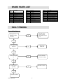
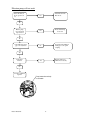
1
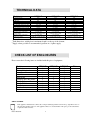
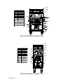
OE7108/F, OE7113/F & OE7105/F
ELECTRIC FILTRATION FRYERS
USER, INSTALLATION AND SERVICING
INSTRUCTIONS
IS335 ECN3226
1
Dear Customer,
Thank you for purchasing this Lincat product.
This is just one of over 300 different items of catering equipment available
which is constantly being extended and improved. Details are available from
your local distributor or direct from us.
Used for the purposes for which it is intended, and with careful maintenance
as outlined in this User Guide, your Lincat product will give you years of
trouble free service.
IMPORTANT INFORMATION
Please read all of the safety and operating instructions carefully before using this
product. Please pay particular attention to all sections of this User Guide that carry
warning symbols and notices.
WARNING!
This is a Warning symbol. This symbol is used throughout the user guide
whenever there is a risk of personal injury. Ensure that these warnings are read
and understood at all times.
CAUTION!
This is a Caution symbol. This symbol is used throughout the user guide whenever
there is a risk of damaging your Lincat product. Ensure that these warnings are read
and understood at all times.
NOTE:
This is a Note symbol. This symbol is used throughout the instructions to provide additional
information, hints and tips.
IS335 ECN3226
2
CONTENTS
Contents
Page
Customer Information……………………………………………………….
Warnings and Precautions…………………………………………………
Technical Data………………………………………………………………..
Check List of Enclosures…………………………………………………..
Component Identifiaction……………………………………………………
Installation…………………………………………………….………………
Commissioning………………………………………………………………
Servicing ………………………………………………………………………
Component Replacement ………………………………………….………
Spare Parts List………………………………………………………………
Fault Finding………………………………………………………………….
Circuit Diagram………………………………………………………………
User……………………………………………………………………………..
Service information…………………………………………………………..
Guarantee………………………………………………………….…………..
2
3
4
4
5-6
7
8-9
9
10-11
12
12-13
14
15-17
18
18
WARNINGS AND PRECAUTIONS
It is mandatory that all appliances are installed, commissioned and serviced by a qualified and
competent person as defined by the regulations in force in the country of installation.
Failure to comply will invalidate the warranty.
All equipment must be earthed to prevent shock.
Do not move this appliance when the tank contains oil.
Hot oil can cause severe burns. Avoid direct physical contact.
Always drain food before frying.
Never put water into the oil, as this will cause splashing and possible overflow of the
tank.
Never put anything other than food into the oil.
Disconnect the unit from the electricity supply before servicing or undertaking any
electrical maintenance.
Parts of this unit may become hot in normal use, therefore suitable precautions must be
taken to avoid accidental contact.
Never leave the unit unsupervised whilst frying.
If the unit should begin to smoke, switch off immediately.
In the event of a fire occurring, water should not be used to extinguish it. It is advisable
to install a suitable fire extinguisher and have a fire blanket within reach of the fryer.
Do not overfill the tank with oil.
Maintain the oil level above the minimum mark to avoid fire risk.
Before switching on the appliance please ensure that the tank is filled with oil to
the specified capacity as indicated in the table overleaf.
Parts which have been protected by the manufacturer or his agent must not be adjusted
by the installer or user.
IS335 ECN3226
3
TECHNICAL DATA
Model
Overall height (mm)
Height to hob (mm)
Width (mm)
Depth (mm)
Tank dimensions1 W x D (mm)
Legs adjustable within range (mm)
Weight (Kg)
Oil capacity (litres) min level mark
Maximum Load (kg) frozen chips
Drain tap diameter
Electricity supply requirements
(3 phase supply)
Electricity supply requirements
(Single phase supply)2
Power rating (kW) total
1
2
OE7108/F
OE7105/F
OE7113/F
1050
900
600
737
550 x 360
135 to 190
102 kg
35 litres
3 kg
25mm
3~, N and earth
1x32 amp or 2x16 amp cable
1~, N and earth
1x100 amp or 2x63 amp cable
22 kW
1050
900
600
737
250 x 360
135 to 190
108 kg
2 x 16 litres
3 kg
25mm
3~, N and earth
1x32 amp cable per tank
1~, N and earth
63 amp cable per tank
2 x 12 kW
1050
900
400
737
165x390
135 to 190
2 x 8 litres
2 kg
25mm
3~, N and earth
1x32 amp or 2x16 amp cable
1~, N and earth
1x100 amp or 2x63 amp cable
2 x 7kW
Tank dimensions; width given is maximum, depth is to the top of the element.
Supply; where possible we recommended operation on a 3-phase supply.
CHECK LIST OF ENCLOSURES
Please ensure the following items are included with this piece of equipment:
Model
Wire basket
Element lifting hook
Batter Plate
Drain Tube
Drain bucket
Filter Bag/ Filter Bag Frame
Filter Bag Cover
Filter Pad Holder
Filter Pads
User/Installation instructions
Guarantee card
OE7108/F
2
1
1
1
1
1
1
1
6
1
1
OE7113/F
2
1
2
1
1
1
1
1
6
1
1
OE7105/F
2
1
2
1
1
1
1
1
6
1
1
Tick
SERIAL NUMBER
NOTE
Each appliance manufactured at Lincat has a unique identifying number found in the top right hand corner of
the data plate attached at the rear of the appliance. Please record that number in the space provided should it be
required for future reference.
IS335 ECN3226
4
Serial Number
MARK OF CONFIDENCE
Every singe product that leaves our factory bears a serial plate showing the assembler’s initials. It’s a
mark of confidence we have in our people and our manufacturing process.
AA
Component Identification
AA
Wire basket support
BB
Knurled fastener
CC
Thermostat Control
DD
Right element on
EE
Power on
FF
Left element on
GG
Operating mode
HH
Pump on
II
RH limit reset
JJ
LH limit reset
KK
Pump reset
LL
Filter bag cover
MM
Element lifting rod
NN
Oil bucket
OO
Drain valve
PP
Filter pad connection
BB
CC
DD
EE
FF
GG
HH
II
JJ
KK
PP
LL
OO
MM
NN
OE7108/F COMPONENT IDENTIFICATION
IS335 ECN3226
5
AA
Component Identification
AA
Wire basket support
BB
Knurled fastener
CC
Thermostat Control
DD
Right element on
EE
Power on
FF
Operating mode
GG
RH limit reset
HH
LH limit reset
II
Pump reset
JJ
Filter pad connection
KK
Filter bag cover
LL
Element lifting rod
MM
Oil bucket
NN
Pump on
OO
Drain valve
PP
Tank selector
BB
CC
DD
PP
FF
GG
HH
II
JJ
KK
LL
OO
NN
MM
OE7113/F COMPONENT IDENTIFICATION
AA
BB
Component Identification
AA
Wire basket support
BB
Knurled fastener
CC
Element on
DD
Power on
EE
Thermostat Control
FF
Pump on
GG
Operating mode
HH
LH limit reset
II
Pump reset
JJ
RH limit reset
KK
Oil bucket
LL
Filter bag cover
MM
Filter pad connection
NN
Drain valve
OO
Tank selector
DD
FF
OO
EE
GG
HH
NN
II
JJ
MM
LL
OE7105/F COMPONENT IDENTIFICATION
IS335 ECN3226
CC
6
KK
EE
INSTALLATION
PREPARATION
Remove all packaging materials and protective coatings prior to installation.
SITING
The appliance must be installed in accordance with the appropriate instructions listed prior.
•
•
•
•
•
•
The appliance must be installed on a level floor in a suitable position that is well lit, and
positioned so as to prevent accidental touching.
On units supplied with legs, the height and level can be adjusted using the spanner provided.
The fryer should NOT be positioned next to any unit that has an exposed flame, such as a gas
range or chargrill.
Partitions, walls, kitchen furniture and other materials less than 100 mm from the appliance
should be made from non-combustible material.
Ensure there is a free flow of air and adequate ventilation around the appliance, and that no vents
are blocked.
It is recommended that the appliance is sited under a canopy for the removal of steam.
ELECTRICAL SUPPLY AND CONNECTION
This appliance must be connected to the electricity supply by a qualified electrician, in
accordance with relevant regulations.
•
•
•
•
•
•
This appliance should be connected to mains electricity via a suitable isolating switch, which
should have at least a 3mm contact separation on all poles.
Remove link wires between terminal blocks (4 off) when connecting to Two Mains Supplies.
The isolator should be easily accessible in the event of an emergency.
Check that the power supply and the supply cable to be used, is compatible with the rating of the
unit.
Remove the rear panel to gain access for connections.
The appliance is fitted with a safety cut out switch on the element mounting that disconnects the
supply to the element when it is raised to the cleaning position. (See user instructions)
IS335 ECN3226
7
COMMISSIONING
Never operate the unit without oil in the tank
PREPARATION
•
•
•
•
•
•
•
•
•
•
•
•
Ensure that the oil drain taps are closed.
Remove the filter pad holder from the oil drain tank
Clean the fryer tank thoroughly with a warm mild detergent solution.
Rinse the tanks, drain pipes and taps, and then dry thoroughly.
Run a small quantity of oil across the bottom of each tank. Open the drain tap and drain any
residual water into the oil drain tank. Coat the base of the tank with a layer of oil.
Close the drain taps.
Empty oil drain tank, dry thoroughly and re-fit oil drain tank back into the base of the fryer.
Ensure:A carbon filter pad is securely fitted in the filter pad holder
The filter pad holder is placed in the oil drain tank
The filter pad holder flexible hose is securely fitted to the pump suction quick coupling
Fill the tank with oil midway between the min and max level marks.
SWITCHING ON
•
•
•
•
With the control knob in the off position and the ‘Filter/fryer mode’ toggle switch in fryer
mode, switch the unit on at the isolator.
The green neon will light.
Turn a thermostat control knob clockwise to the required temperature.
The adjacent amber neon will light, indicating that the heating elements are energised.
OPERATIONAL CHECK
Although all Lincat fryers are functionally checked during manufacture, commissioning
must include a functional check of all controls.
FRYER MODE
•
•
Set the thermostat to 1900C and allow the oil to heat up.
Use a suitable device to check that the temperature of the oil. At a position 25mm below the
surface of the oil, at the geometric centre of the tank, the oil temperature should be within +/50C of the set temperature.
IS335 ECN3226
8
FILTER MODE (pumping system)
HOT OIL – Wear protective clothing, gloves and safety glasses.
On the twin tank fryers, filter one tank at a time.
•
•
•
•
•
•
•
•
•
•
•
Set the thermostat control knob to the off position and the ‘Filter/fryer mode’ toggle switch in
filter mode.
The green neon will go out.
Ensure the filter pad holder tube is connected correctly to the quick release coupling.
Open the drain valve and allow the oil to drain.
Close the drain valve.
Press and hold (for 5 seconds) the ‘pump On’ momentum switch, the pump will start and hot
oil will start to be pumped back into the fryer tank.
Release the momentum switch, the pump will continue to run until all the oil has returned to
the fryer tank at which point the pump will automatically turn off.
Note:- The pump can be turned off at any time by switching the ‘Filtration/fryer mode’
toggle switch back to fryer mode.
Repeat this procedure for the second tank on a twin tank fryer.
Switch the ‘Filtration/fryer mode’ toggle switch to fryer mode.
The green neon will light.
This manual together with the user instructions must be kept in a safe and accessible
place for future reference.
A small amount of oil will remain in the bottom of the drain tank.
Ensure that the person responsible understands how to safely operate, clean and shut down
this appliance and is made aware of the position of the isolating switch.
SERVICING
ROUTINE SERVICE
We recommend that all servicing, other than routine cleaning, be carried out by our authorised
service agents.
•
•
•
•
•
Carry out a general check on the installation paying particular attention to the following:o Is the unit installed with the correct rating of cable.
o Is it connected to the supply via a suitable isolating switch.
Check all components for correct operation and replace where necessary.
Check the operation of the high temperature limit thermostats. The reset buttons are located
inside the unit, on the rear panel, see diagram.
Check the operation of the element safety switch by raising the elements, and ensuring that
the elements cannot be switched on.
Check the pump operation, the quick release coupling and plug connection and flexible hose
condition and that there is no evidence of leaks on the filtration circuit.
IS335 ECN3226
9
COMPONENT REPLACEMENT
Disconnect all power supplies from the mains before proceeding.
CONTROL THERMOSTAT
•
Isolate the unit from the mains supply
•
Drain the tank into the oil drain tank.
•
Remove the small gland assembly nut, unclip and then withdraw the thermostat phial.
•
Remove the control knob taking care not to lose the knob retaining clip.
•
•
Remove the control panel retaining screws and with the door closed, free the control panel by
sliding it downwards.
Support the control panel, remove the screws that retain the thermostat to the control panel.
•
Reassemble in reverse order.
SAFETY THERMOSTAT.
•
Isolate the unit from the mains supply
•
Remove the basket support and element cover, flue back, and the rear cover. Remove the
capillary support bracket on the flue panel.
•
Unscrew the thermostat from the inner back panel.
•
Raise the elements using the element raising hook. Unclip the thermocouple phial and the
capillary tube from the element legs. Unhook the coiled capillary from around the capillary
support tube.
•
Reassemble in reverse order. Ensure that the coil diameter around the capillary support tube
is 15-20mm diameter and that a left hand or right hand coil of 4 turns is formed, depending
on which side of the unit it is being fitted to.
Capillary support bracket
Element leg
Coil hooks over cut-out
in hobtop
Capillary coil
Capillary support tube
IS335 ECN3226
10
CONTACTOR
•
•
•
•
•
Isolate the unit from the mains supply.
Remove the rear cover.
Remove the spade connections to the contactor.
Remove the contactor from the frame.
Reassemble in reverse order.
SAFETY CUT-OUT
•
•
•
•
•
•
Isolate the unit from the mains supply.
Raise the elements.
Remove the rear cover.
Remove the two screws to release the safety cutout switch.
Remove the cutout switch.
Reassemble in reverse order.
HEATING ELEMENT
•
•
•
•
•
•
Isolate the unit from the mains supply.
Remove the rear panel.
Remove the wire basket support and element cover.
Remove the flue panel retaining screws that fix it to the hob top.
Access can now be gained to the element connections and fixing nuts.
Reassemble in reverse order, use a silicone seal to block the keyhole slot in the element
swivel plate.
PUMP/MOTOR UNIT
•
•
•
•
•
•
•
Isolate the unit from the mains supply.
Remove the rear panel, door/s and the left side panel
Undo the control panel and support.
Disconnect the pump inlet and outlet pipes.
Remove the live, neutral and earth connections.
Undo the four motor mounting bolts and remove the pump/motor unit.
Reassemble in reverse order.
PRESSURE SWITCH
•
•
•
•
•
•
Isolate the unit from the mains supply.
Remove the rear panel
Disconnect the sensing line pipe from the pressure switch.
Remove the electrical connections.
Remove the pressure switch.
Reassemble in reverse order.
IS335 ECN3226
11
SPARE PARTS LIST
Part
number
BA82
BA83
BO03
CA112
CA113
CO112
DR06
EL180
EL185
EL220
Description
Basket
Basket (OE7105/F)
Basket support boss
Braked castor
Unbraked castor
Contactor
Drawer runner
7kW element OE7105/F
11kW element OE7108/F
12kW element OE7113/F
FB03
FP06
HA77
HA78
KN225
LE14
NE39
NE40
OA7937
OP01
PS03
SW34
Filter bag
Filter pad holder
Door handle
Lid handle
Control knob
Lens cover
Green neon
Amber neon
(30 Pack) Filter pads
Pump/motor
Pressure switch
Mode switch
SW35
SW38
TA100
TH62
TH59
TH79
TH61
TH78
WI13
WI09
WI14
FAULT FINDING
Fryer will not heat up
Is the green neon
illuminated on the
front facia
Check the mains
isolator and fuse
Check unit is in fryer
mode.
No
Yes
Is the thermostat
turned on
No
Turn on the
thermostat
No
Check if the limit
stat needs resetting
Yes
Is the amber light
on
Yes
Is the contactor
operating
Check the contactor
No
Yes
Check the element
IS335 ECN3226
12
Pump switch
Safety switch
Drain tap
Control thermostat OE7105
Control thermostat OE7108
Control thermostat OE7113
Limit thermostat OE7108
Limit thermostat OE7113
Wire basket support OE7105
Wire basket support OE7108
Wire basket support OE7113
Filtration pump will not work
Is the unit in fryer
mode (green neon
on)
Switch the unit into
filter mode.
Yes
No
Has the pump
motor thermal
trip activated
Yes
Reset thermal trip
See below
No
Correctly fit the filtration
return pipe to the quick
coupling
Yes
Replace filter pad,
unblock as necessary
No
Is the filtration return
pipe correctly fitted
Yes
Is the filter
blocked
No
Consult a qualified
engineer
IS335 ECN3226
Pump/motor thermal trip
reset button
13
P
CIRCUIT DIAGRAM
Pressure Switch
P
IS335 ECN3226
Pump
Momentary Switch
Fryer Mode
Mains On Neon
t°
Interlock
Switch
Control
Thermostats
t°
Fryer/Pump Mode
Changeover Switch
14
Fryer Mode
Mains On Neon
Heat 'On' Neon
Heating
Element
Limit
Thermostat
OE7108/F
OE7113/F and OE7105/F
Contactor
Heat 'On' Neon
Contactor
Heating
Element
Limit
Thermostat
L3
L2
L1
USER INSTRUCTION
Model No.
OE7105/F
OE7108/F
OE7113/F
Capacity
2 x 8 litres
35 litres
2 x 16 litres
Basket load
1.0 kg
1.5 kg
1.5 kg
Never operate the pump without the carbon filter pad fitted into the pad holder.
Always use the correct filter pad. Lincat part number OA7937 (30 pack)
FILL WITH OIL
•
•
•
Remove the dust cover and locate it behind the wire basket support at the rear of the tanks.
Check that the drain taps are closed in the safe locked position (see “Cleaning the tanks”).
Fill the tank of the fryer to the higher of the two level marks on the rear tank wall.
OPERATION
Always check that there is oil in the tank before switching on the appliance.
Do not fill above the higher of the two level marks
•
•
•
•
Turn on the power supply at the isolating switch, with the ‘Filter/fryer mode’ toggle switch
selected to fryer mode the green neon will light indicating the unit is in fryer mode and that
mains power is on.
Turn the thermostat control knobs to the required temperature setting.
The amber neons will light indicating that the heating elements are energised.
When the oil in a tank reaches the selected temperature, its associated amber neon will go
out.
BASKET LOADS
Overloading the basket reduces the fryer output of cooked product and will result in uneven cooking.
It also increases the possibility of surge boiling (the oil may suddenly boil over when the basket is
placed into the tank).
Food that is over-wet increases the possibility of surge boiling.
IS335 ECN3226
15
WARNING HOT OIL – Wear protective clothing, gloves and safety glasses.
Do not operate the filtration system without a filter pad fitted to the filter pad holder.
FILTERING, OIL CHANGE AND CLEANING INSTRUCTIONS
On the OE7113/F and OE7105/F models, drain and filter one tank at a time.
A small amount of oil will remain in the bottom of the drain tank.
The pump can be turned off at any time by switching the ‘Filter/fryer mode’ toggle
switch back to fryer mode
FILTERING THE OIL
• Set the thermostat to the “Off” position with the orange dot at the top of the control dial.
• Open the fryer doors.
• Set the switch to Filtration mode located in the top right-hand corner.
• Fully pull out the oil tank using the attached handle.
• Check the filter bag is positioned correctly in the four locating holes within the drain tank.
• Fit the supplied drain tube ensuring it is pointing down in to the filter bag by screwing it into
the drain value as shown using both hands.
• Fit the supplied splash guard over the filter bag.
• Open the drain valve and completely drain the hot oil.
• Fully close the drain value.
• For the OE7113/F and OE7105/F model, set the tank selector ‘PP’(see page 6 and below) to
return the oil to the correct tank.
• Press and hold the pump switch for a few seconds until the pumping starts. (The pumping
operation will stop automatically when complete).
• Remove the splash guard, drain tube, filter bag, batter plate and baskets onto a tray to prevent
oil dripping on the floor, then clean through a dishwasher, dry then return for next time.
• Return the switch to fryer mode and push the drain tank fully back in for storage
• Close the doors.
This setting will
return oil to the
Left-hand tank
Do not operate the
pump with the lever
set in this position
This setting will
return oil to the
Right-hand tank
Correct operation of the oil return valve.
OIL CHANGE AND CLEANING OF THE COLD FRYER
The oil must only be emptied from the fryer when it is cool. Therefore the oil must only be drained
as the first task of the morning after the oil has been allowed to cool overnight.
• Isolate from the power supply by turning the power off before cleaning.
IS335 ECN3226
16
• Set the thermostat to the “Off” position with the orange dot at the top of the control dial.
• Open the fryer doors and fit the supplied drain tube ensuring it is pointing into the container.
• Please stand your empty oil container in a tray as this will help prevent any spillages or drips
on the floor.
• Fill the empty container with the old oil by opening the drain value
• Do not leave the container unattended you will need to stop the filling by closing the drain
valve!
• Replace oil container lid and remove. Remove drip tray and clean in dishwasher.
• Remove the basket support bar by lifting upwards.
• Remove the back plate by turning the screws and lifting off.
• Remove batter plate from inside the tank onto a drip tray and then clean through the
dishwasher.
• Lift the elements with the supplied tool by hooking under the element and lifting after
depressing the element release button see ‘Detail A’.
• The element will park ready for cleaning.
• Remove large partials using a suitable tool such as a chip shovel.
• Use paper towel or similar to remove any small partials of debris.
• Make sure the drain valve is closed before using any cleaning liquid.
• Wash the interior of the fryer tank with a mild detergent, drain as instructed before into a
Stainless steel bucket.
• Release the filter pad holder from the quick release coupling and remove the drain tank from
the fryer.
• Remove the filter pad from the holder and disgard, clean all items through the dishwasher.
• Using the element tool hook under the element then press the release button and lower the
elements
• Replace the back plate and secure.
• Refit the basket supports and batter plate.
• Check that the drain valve is fully closed
• Fryer is ready for filling with new oil
Element latch release button
DETAIL A
A
The elements can be raised out of the tank to allow easy access for debris removal and cleaning.
Both elements lift simultaneously using the lifting hook provided. As the elements are raised to the
parked position, a safety switch fitted to the element mounting plate at the rear of the fryer
IS335 ECN3226
17
disconnects the power supply. The elements are reconnected to the power supply as they are returned
to the operating position
SERVICE INFORMATION
Catering equipment should be routinely serviced to ensure a long trouble free life. It is recommended
that this appliance is serviced every 6 months by a competent engineer.
For help regarding the installation, maintenance and use of your LINCAT equipment, please call:-
LINCAT GROUP SERVICE HELP DESK
+44 (0) 1522 875520
AUTHORISED SERVICE AGENTS
We recommend that all servicing other than our authorised service agents carry out routine cleaning.
We cannot accept responsibility for work carried out by other persons.
Please quote both the model and serial numbers from the data plate attached to the unit. Give brief
details of the service requirement.
If possible please quote the product code of the part number you require.
Work carried out under warranty will normally be undertaken only during normal working hours, i.e.
Monday to Friday, 8.30 a.m. - 5.30 p.m.
CONDITIONS OF GUARANTEE
The guarantee does not cover:1)
2)
3)
Accidental breakage or damage
Operational misuse, wear and tear from normal usage, incorrect adjustment, or neglect.
Incorrect installation, maintenance, modification or unauthorised service work.
IS335 ECN3226
18